

OHM-Stat CT-8900 Owner's Manual
OHM-STAT
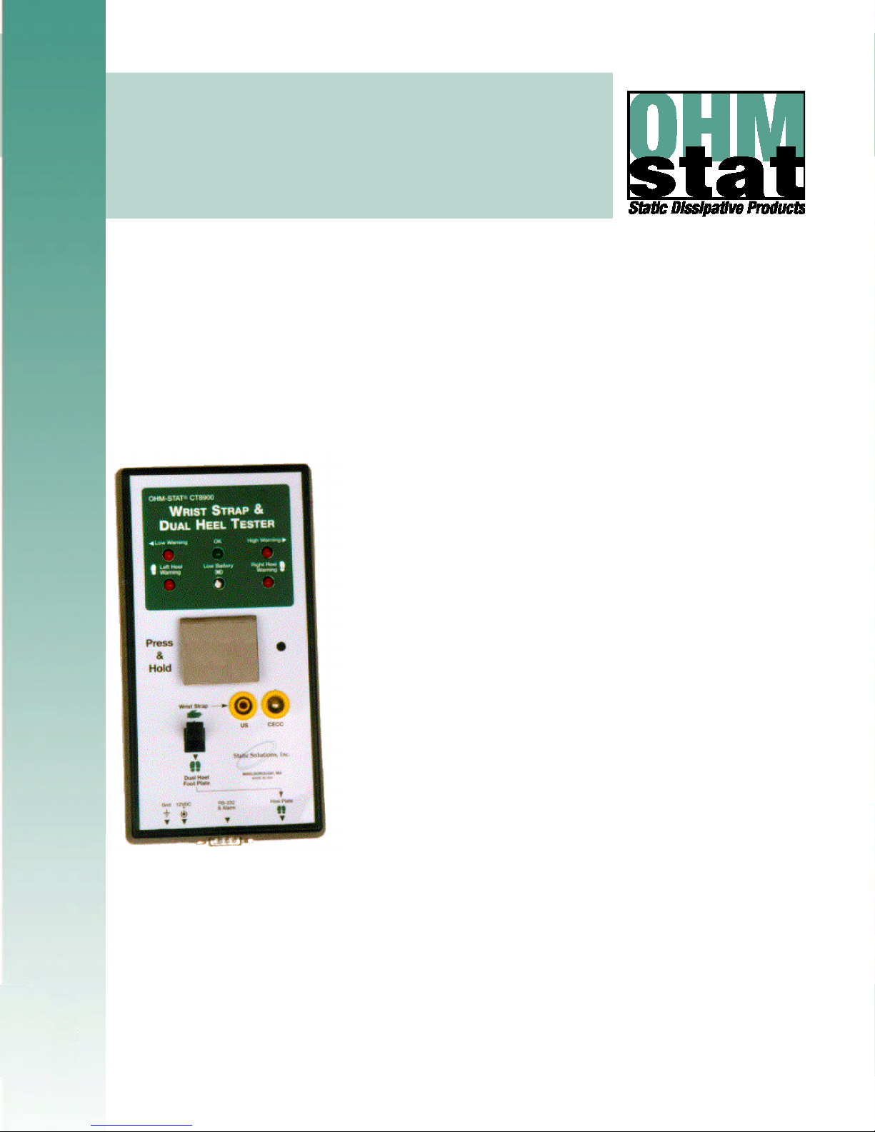
CT-8900
OWNERS MANUAL
& OPERATION GUIDE
DATA LOGGING WRIST AND FOOT STRAP COMBO TESTER KIT
Includes software, calibration data, bar code,
magnetic stripe and proximity card reader instructions
(For OHM-STAT CT-8700 Wrist and Foot Strap Combo Tester Kit,
disregard references to data logging, software, and card readers)
SOFTWARE VERSION: __________
SERIAL NUMBER: __________
COMPANY: ______________
MANUAL PRICE: $25.00 US
Static Solutions CT-8900 Combo Tester Instructions 7/22/2009
Ver 7/22/2009/s
For software Ver 9.33 or higher, and Testers manufactured after 3/12/2002
1

TABLE OF CONTENTS
INTRODUCTION................................................................................................................ 4
FEATURES:................................................................................................................................................................................ 5
CALIBRATION VERIFICATION ................................................................................................................................................. 6
ISO TRAINING AND CERTIFICATION OF ESD HANDLING AND CONTROL MEASURES FOR OPERATORS ................... 7
Objectives ........................................................................................................................................................ 7
Qualification and Certification Testing ............................................................................................................. 7
Standards Compliant ....................................................................................................................................... 7
Learning station system requirements............................................................................................................. 7
Setup of training courses ................................................................................................................................. 7
Training Program Sequence of Events............................................................................................................ 8
TESTING OF WRIST STRAPS AND FOOTWEAR .................................................................................................................... 9
BASIC SETUP................................................................................................................. 10
EQUIPMENT............................................................................................................................................................................. 10
Equipment Required ...................................................................................................................................... 10
Equipment Provided....................................................................................................................................... 10
Equipment Options ........................................................................................................................................ 10
HARDWARE INSTALLATION.................................................................................................................................................. 11
Before You Begin........................................................................................................................................... 11
Meter Assembly ............................................................................................................................................. 11
Meter Adjustments......................................................................................................................................... 12
Dip Switch Settings for 100M unit.................................................................................................................. 13
Dip Switch Settings for 1000M unit special unit ............................................................................................. 14
Door Relay..................................................................................................................................................... 15
SOFTWARE INSTALLATION GUIDE ...................................................................................................................................... 18
Software Installation for First Time Installation of New Software................................................................... 18
Software installation for Upgrading to a Minor Version Change .................................................................... 18
Software Installation for Upgrading to a Major Version Change .................................................................... 18
STARTING THE PROGRAM .................................................................................................................................................... 19
Help................................................................................................................................................................ 20
CARD READER INSTALLATION INSTRUCTIONS................................................................................................................. 21
Keyboard Wedge and USB Bar Code Reader or Magnetic Stripe Reader Installation.................................. 22
Trouble Shooting if Scanner Does Not Read Correctly ................................................................................. 23
USB Reader Installation................................................................................................................................. 24
Trouble Shooting if USB scanner Does Not Read Correctly.......................................................................... 24
General RS232 Reader Installation ............................................................................................................... 25
Trouble Shooting If the RS232 reader card does not work............................................................................ 26
CASI-RUSCO
Trouble Shooting If the card does not work. .................................................................................................. 27
PROGRAM SETTINGS............................................................................................................................................................. 29
General Configuration.................................................................................................................................... 29
Change Administrator Password ................................................................................................................... 31
Unknown ID Configuration’ ............................................................................................................................ 31
User Information ............................................................................................................................................ 32
Directories...................................................................................................................................................... 34
Change Employee Password......................................................................................................................... 34
Certification Configuration.............................................................................................................................. 35
Remote Data Base Setup for accessing employee names............................................................................ 35
Remote Data Base Setup for storing resistance test data ............................................................................. 39
Multiple Station Configuration and operation................................................................................................. 41
Language Display .......................................................................................................................................... 43
94x, 97x weigand, HID 5352, HID RW-400, AWID SP-6820 RS232 reader Installation27
Static Solutions CT-8900 Combo Tester Instructions 7/22/2009
2

OPERATION.................................................................................................................... 44
OPERATOR TESTING INSTRUCTIONS WHEN NOT USING THE COMPUTER ................................................................... 44
OPERATOR TESTING INSTRUCTIONS WHEN USING THE COMPUTER............................................................................ 45
Troubleshooting high wrist readings: ............................................................................................................. 45
Troubleshooting low wrist readings:............................................................................................................... 45
Troubleshooting high foot readings:............................................................................................................... 45
Troubleshooting low foot readings:................................................................................................................ 45
Example of program waiting for the test button to be pressed:...................................................................... 46
Example of a good reading:........................................................................................................................... 46
Example of a low wrist reading: ..................................................................................................................... 47
Example of a high wrist reading:.................................................................................................................... 47
Example of a multiple high readings:............................................................................................................. 48
Example of a miscommunication reading caused by releasing the test button prematurely: ........................48
REPORT GENERATION: ......................................................................................................................................................... 49
Monthly report................................................................................................................................................ 49
Entire Log report ............................................................................................................................................ 50
Daily report..................................................................................................................................................... 50
Individual test log report................................................................................................................................. 50
Exceptions report........................................................................................................................................... 51
Twice Tested Exceptions report..................................................................................................................... 52
Certification Expiration report......................................................................................................................... 53
Individual Attendance report .......................................................................................................................... 53
Monthly Vacation (Attendance) report ........................................................................................................... 53
Automatic Emailed Reports ........................................................................................................................... 54
LogSort Notes................................................................................................................................................ 58
TOOLS...................................................................................................................................................................................... 59
ADVANCED FEATURE SETUP ...................................................................................... 61
NETWORKING THE CT-8900 TESTER ................................................................................................................................... 61
Test Station Computer Setup......................................................................................................................... 63
Server Computer Setup ................................................................................................................................. 63
Synchronizing Test Station System Time ...................................................................................................... 63
EsdTest File Administration ........................................................................................................................... 64
INTERFACING WITH OTHER DATA BASES.......................................................................................................................... 65
Importing Log files to Excel:........................................................................................................................... 65
Exporting Name.txt file from Excel:................................................................................................................ 65
Importing Files To Microsoft Access:............................................................................................................. 66
Exporting the Names.txt File From Microsoft Access: ................................................................................... 66
Reading the Employee Names Directly From the Company Data base ........................................................ 66
SPECIFICATIONS:.......................................................................................................... 67
MAINTENANCE AND CALIBRATION............................................................................. 68
MAINTENANCE........................................................................................................................................................................ 68
CALIBRATION TESTING ......................................................................................................................................................... 68
TROUBLESHOOTING AND FREQUENTLY ASKED QUESTIONS (FAQ)..................... 69
WARANTEE AND LICENSE AGREEMENTS ................................................................. 76
LIMITED WARANTEE: ............................................................................................................................................................. 76
Exclusions...................................................................................................................................................... 76
Limitations:..................................................................................................................................................... 76
SOFTWARE LICENSE AGREEMENT; .................................................................................................................................... 76
Static Solutions CT-8900 Combo Tester Instructions 7/22/2009
3
INTRODUCTION
Congratulations on purchasing your new CT-8900 data-logging wrist and foot strap testing kit!
This is the finest tester available on the market.
The CT8900 combo meter is an instrument that concurrently measures the resistance of a wrist strap and
two foot straps within a few second period. The measurements are sent to a computer and can be judged for
valid readings, and then logged to a file. Many additional services are available as shown in the following
“features” section, such as having reports directly emailed to supervisors.
A typical test station consists of a badge reader to identify the user, the CT8900, a computer, and a monitor.
The user scans his badge and tests his straps. Multiple test stations are connected via an Ethernet network
to a common server that combines the data and issues reports.
For economy, multiple meters may be connected to one computer, but the user looses the ability to see the
direct readings on the monitor, and instead relies on the visual LED indicators on the meter.
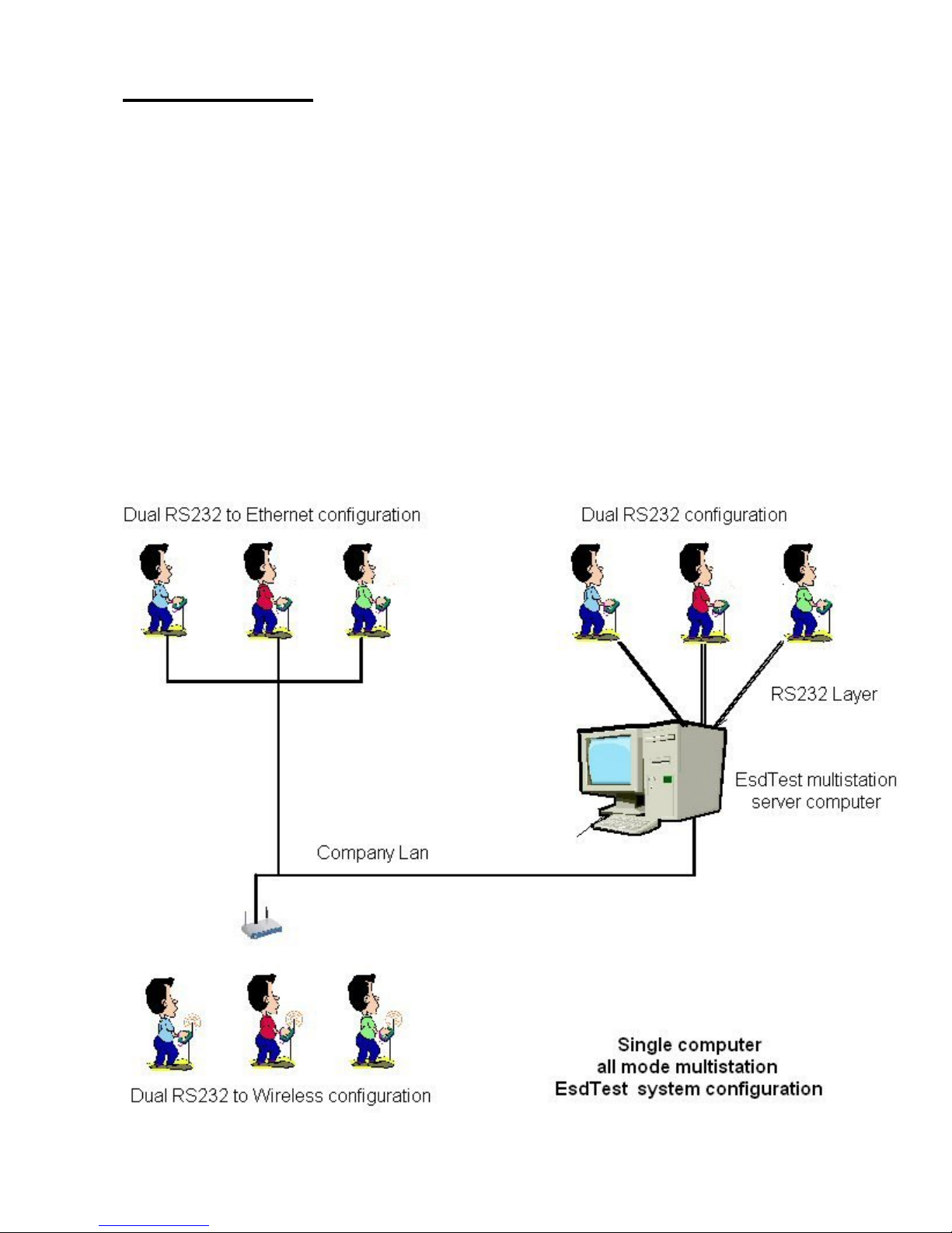
The RS232 output allows many connection options:
Direct connection of one meter to a computer RS232 port (standard method)
Connection to a computer USB port via an inexpensive RS232 to USB converter
Connection of multiple readers to a single computer with our serial multi-port card option
Connection of multiple readers to a single computer with our RS232 to Ethernet converter option
Connection of multiple readers to a single computer with our RS232 to wireless LAN converter option
Static Solutions CT-8900 Combo Tester Instructions 7/22/2009
4

FEATURES:
- Reads actual resistance of the strap from 100 kilohms to 100 megohms
and up to 1000megohms for new 1000M unit.
- Alarm points may be programmed to any value for any user
or the combo tester limits can be automatically used.
- Accepts up to 30,000 employees
- Easy to use: employees step on the foot pads,
plug in their wrist strap,
scan a proximity card or barcode
( or click on their name)
(or type in the first few letters of their name)
(or type the line number of their name)
(or type their ID number)
and push a button
- Generates and prints
-- monthly test results reports
-- daily event logs
-- continuous event logs
-- event logs for any employee over any time span
-- employee failure exception reports
-- certification expiration report
-- certification training exam report
-- attendance summary
-- vacation summary
-- labels for employees that pass the esd test
- Employee leave status(sick, vacation etc.) can be stored.
- Reports can be limited to specific work groups.
- Report files may be easily imported into other spreadsheets or data bases.
- Reports can be automatically generated and emailed.
- Requires a password to change the parameters and access the data.
- Can optionally require an individual password for each employee to test.
- Can read employee bar code badges or cards (via keyboard wedge).
Can use first, last, or middle n characters of the barcode.
Can ask employee to type in name if new badge is read.
- Can read employee proximity card with following readers:
HID 5352 or RW-400 RS232 reader.
Casi-Rusco 94x, 97x Wiegand reader
Motorola, Indala
Awid Sentinel-Prox SP-6820 reader
General RS-232 readers
- Can be used without a monitor.
- Is able to open a door if straps are in tolerance. As an accessory
- Is able to prevent unauthorized entry without the proper badge.
- Can warn employee of impending certification expiration.
- Can limit access of employees with expired certification.
- Runs on any Windows 98, ME, NT, 2000, or XP compatible PC.
- Uses any standard RS-232 communications port
- Uses a standard dual DB9S (female) connector RS-232 cable
- Can use a USB port with a USB to fully compliant RS-232 port adapter.
- Can accept and display International dates and numbers
- Program window can be minimized only with correct password.
- Multiple stations can be connected to a network.
- A networked station will still operate even if the network malfunctions.
- Can read employees from a remote SQL data base.
- Can store test data to a remote SQL data base (Oracle, SQL2000, Access, etc).
- Optional certification training courses available.
- Reads training course data bases to determine which employees are certified.
- Can connect multiple stations to one computer.
- Can record exit times.
- Testing window can be displayed in English, Spanish, Portuguese, Italian, Polish, Hungarian, or Chinese.
- Data base can be easily read, edited, imported, and exported by a variety of programs.
- Data base (.txt file) is virus and worm proof
Static Solutions CT-8900 Combo Tester Instructions 7/22/2009
5

TERMINOLOGY
Static fields can build up on humans as they walk along an insulative surface such as a carpet. A person with a high voltage static
charge can destroy or damage an integrated circuit or FET device either by touching or coming close to it. Thus most electronic
assemblers wear wrist straps or heel grounders to keep the wearers at the same voltage potential as the parts they are assembling.
Wrist straps and heel grounders/shoes may also be worn at chemical plants, explosive materials factories and storage areas.
A
wrist strap is simply a resistorized conductive cord that connects the wearer’s wrist to a grounded conductive mat that covers the
assembly bench. The resistor protects the static sensitive device as well as the worker.
A
heel grounder is a small resistorized strap that connects the wearer to their special conductive floor surface. This requires that
the floor be covered with a grounded conductive carpet, tile, mat or dissipative floor wax or paint (available through Static Solutions).
It is important that two heel grounders/shoes be worn to achieve proper static discharge.
Wrist straps and heel grounders simply act as a wire to drain off charges. However, to prevent accidental electrocution of the wearer
(should the wearer inadvertently touch an external high voltage source) a high resistance is built into the strap. The resistance is
typically between .5 to 2 megohms.
Thus straps and heel grounders have to be tested for two different malfunction conditions. If there is an open circuit or too high a
resistance, then it will fail to prevent high voltage build up and no longer control dissipation. If there is a short circuit or too low a
resistance (such as wet shoes), then it could fail to prevent electrocution, or could cause a rapid discharge which could emit a spark
or cause a secondary effect.
The
Wrist Strap and Dual Heel Tester checks the controlled conductive integrity of wrist straps and heel grounders/shoes for both
of the fault conditions mentioned above. It can be attached to a free stand or can be a wall mounted. For use, the wearer simply
inserts their wrist strap banana plug into the instrument, and stands on the foot plates (if wearing heel grounders or shoes), and
presses the button. An LED display shows the results of the test (OK, low or high), and an alarm sounds if the resistance is not
within its preset limits, and if the correct person and/or card is correctly identified from the data base. If the card or person is not
recognized, there will be no LED lights and there will be a buzzer sound emitted.
If the computer data logging option is used then the actual resistance is displayed on the monitor, is automatically recorded in the
computer, and can be printed in a daily/monthly report. If the resistance is changing day by day, the CT-8900 can be a valuable tool
to predict failures before they occur.
Unlike other testers, the CT-8900 Dual Heel Tester tests both feet and wrist at once and separately, and does not require the wearer
to shift feet and repeat the test. This saves time, and can insure proper testing. The CT-8900 cannot be fooled by a wearer who
dislikes wearing two grounders and merely presses the button twice while stepping on the footplate with the same foot.
The EOS 20/20 standard mandates that a company must record the results when a person tests their wrist/heel straps to enter a
static sensitive area, or must use a constant wrist strap monitor. In either case, when using shoes or heel grounders, a record must
be kept. If a constant wrist strap monitor is used, the CT-8900 will test it as well, and notify the user if it has failed.
The tester software can generate a number of reports, including informing the supervisor if the wearer does not perform a test once
or twice a day.
CALIBRATION VERIFICATION
The CT-8900 meter is calibrated to NIST traceable standards. The meter self calibrates itself with each use by comparing the
surface mounted 1-megohm resistor value and capacitor against the unknown value. After one year of use, the meter can be sent to
Static Solutions, Inc. to be re-calibrated and be issued a new NIST traceable certificate. Please call Static Solutions for the cost of
this service.
Static Solutions CT-8900 Combo Tester Instructions 7/22/2009
6

ISO TRAINING AND CERTIFICATION OF ESD HANDLING AND CONTROL MEASURES FOR
OPERATORS
A comprehensive interactive multimedia learning program with certification for those who work with static sensitive devices is
available as an option. The training is directed to assemblers and support personnel.
Objectives
Participants successfully completing the program will be able to:
Describe conditions most likely to cause uncontrolled electrostatic discharge
Identify three types of ESD protective packaging
Explain the use of ionization and topical antistats for static control
Describe the impact of environmental factors on static charge
Describe the function of ESD protective items in a protected area
List the requirements of an ESD protective workstation
Describe the correct use of ESD protective smocks, wrist straps, and footwear
Recognize correct use of personal protection around high voltage hazards
List recommended ESD protective practices at workstations
Qualification and Certification Testing
The training course incorporates interactive learning checks throughout the instructional sequences. Certification tests are criterionreferenced and module-based with feedback on every response for enhanced learning. The tests also include a scorebar to provide
the learner with continuous status information. Administrative access to dates and scores of tests, certifications, and re-certifications
is compliant with ISO quality-standards requirements.
Standards Compliant
The courses meet and comply with the ANSI/ESD S20.20 ESD control program guidelines as well as to JEDEC JESD625, IEC
61340-5, and IPC-610 standards.
Learning station system requirements
Install the training course software on the computer that the employees will be trained. The computer learning station will require:
a PC style Pentium class computer with a Microsoft operating system Windows 2000/XP is preferred.
a color monitor
speakers.
a network connection to the EsdTest server so that the EsdTest server can read the training course data base
an internet connection to transfer license codes over.
Setup of training courses
The training course is sold on a per seat license basis. A separate license seat must be pre purchased from Static Solutions for each
employee who takes the course. Once the course is taken, a license seat is good for a 12 month period. If you have not purchased
a group of license seats yet, please contact Static Solutions.
The training course installation software is located on our EsdTest installation CD. After installing the EsdTest software, a window
will appear and ask if you would like to install the training software. The software can also be installed later by opening the
LTechCP1 subdirectory on our installation CD, and running Setup.exe. The training course installation manual
LTechInstallationGuide.pdf is also located in that subdirectory.
Install the software on the training course CD, as per the installation directions contained in the training course CD package. Once
the course software is installed, the course software will ask for the company name, telephone number, and email address. Once
this information has been entered, the registration license number will be emailed back, and they can then be entered (or cut and
pasted from the email) into the training program. The company ESD administrator can than either register the IDs of all the
employees who will be taking the course (has to be the same ID as the one entered into the EsdTest sytem data base) into the
training course system, or the employee/trainee can enter his/her employee ID when first registering to take the training course.
Once registered, the trainee can sign in with just his name and ID number.
Static Solutions CT-8900 Combo Tester Instructions 7/22/2009
7

The AutoGenerate email report task scheduler should be setup to run the "Training" report every week or so.
Training Program Sequence of Events
1. Employees normally test their straps at the EsdTest station before entering the ESD sensitive work area.
2. A month or so before the employee's certification is due to expire, the test station will flash a warning.
3. Sometime during the next month, the employee should then spend one to two hours taking the recertification training
course at the learning station computer. They must log in with their EsdTest ID number.
4. The EsdTest server periodically runs the "Training" report in the Auto email report generator task scheduler which then
searches the training course data base for all similar employee ID numbers that are in the EsdTest data base, and updates
the EsdTest data base certification dates with the date the employee passed the training course. The report will list all
employees who have recently passed the training course.
5. If the employee does not pass the course before his/her certification date expires, they will not be allowed to test their
straps (if the EsdTest certification window setup has been so configured).
6. To generate a list of expired or soon to expire employee certifications, run the Certification report.
Static Solutions CT-8900 Combo Tester Instructions 7/22/2009
8

TESTING OF WRIST STRAPS AND FOOTWEAR
Daily testing of wrist straps and footwear is mandatory to ensure the grounding devices function properly and to minimize charge
generation on the human body, which may cause damage to integrated circuits. Partially conductive footwear and wrist straps
are the primary techniques used to drain and minimize electrical charges from the body. The wrist and foot straps typically have
a 1 megohm or two megohm resistor built into them. Too low a resistance can cause rapid discharge resulting in sparking and
failures. Low resistance wrist or foot straps can also cause an electrical shock to the operator if he touches a high voltage circuit.
On the other hand, open circuit or broken straps can cause high electrical resistant paths that result in static buildup, arcing, and
integrated circuit damage.
To adapt to ISO-9000 certification the results should be recorded in a computer database or printed to hard copy as specified in
EOS 20/20 specification.
Static Solutions CT-8900 Combo Tester Instructions 7/22/2009
9

BASIC SETUP
EQUIPMENT
Equipment Required
1. A computer with a 486DX or higher (Pentium or similar) microprocessor. Larger hard drives (2 G or more) will store more
employee data.
2. Windows operating system (Windows 98/ME/NT/2000/XP).
3. An operable serial communication (comm.) port with the standard +/-12 volt signal levels, (or a USB port with a fully compliant
+/-12V RS232 to USB converter) on the computer. HID/CASI-RUSCO/MOTOROLA
USB port. The RS232 versions require an additional serial communication port (or USB to RS232 converter). Note that some
laptops may not use the full legal standard +/-12 volt RS232 comm. port signal levels, so they will not work, in which case use
an RS232/USB converter..
4. A LAN network-able system is needed for networking multiple testers. This may be a hard wire or wireless modem. (Static
Solutions is not responsible for the installation or maintenance of the network after the software is installed.)
5. To use e-mail feature, users will need a MAPI compliant e-mail program such as Microsoft Outlook 2000 (without the email
security update) or Outlook Express. Eudora (www.eudora.com) also claims to be MAPI compatible.
Equipment Provided
1 – CT-8900 meter unit 1 – FP-8755HD-Foot Plate*
1 – AC power adapter 1 – FS-8900 Foot Stand
1 – 9 volt battery-alkaline 1 – RS-232 Cord- must be used
2 – CD with Software Hook/Loop strips (For use with meter)
*Found on bottom of foot stand –Allen head bolts and Allen head wrench.
/AWID USB proximity readers require a
Equipment Options
1. PS2 connector for laptop connection
2. Barcode scanner (BC-8950)
3. Magnetic stripe reader (MS-8950)
4. HID
5. Casi-Rusco
6. USB to fully compliant +/-12V RS232 serial adapter
7. Low profile footplate (FP-8755LP)
8. Rechargeable 9V battery – will be continuously recharged by RS232 power.
9. Certification training courses
Proximity Reader(HR-8000HID) with two plug power supply adapter
Reader (CRR- 800CR ) with two plug power supply adapter
Static Solutions CT-8900 Combo Tester Instructions 7/22/2009
10

HARDWARE INSTALLATION
Before You Begin
1. Make sure that a sample identification card has been sent to Static Solutions for proper programming of reader.
2. Read the manual, help files, and other files on the C:\EsdTest directory.
3. If user will not be using the software function of the CT-8900 meter, disregard the software instructions in this manual.
4. Install the meter in view of the computer monitor, so employees that are testing can view the test results.
5. Take a deep breath, and know that with the innovative product line of Static Solutions there is instant peace of mind.
6. At anytime, please contact Static Solutions technical staff or refer to
Technical questions should be directed to
7. Program updates are available at www.EsdTest-SS.com.
Meter Assembly
1. For HID/CASI-RUSCO/Indala/Motorola proximity card RS232 readers, two nine pin serial ports (or one if using an RS232 to
USB converter for the card reader) are required on your computer. One for the CT-8900 meter and one for the HID/CASIRUSCO
proximity reader. The supplied RS-232 cords must be used. If there is a 25 pin DB25P on the computer, a DB25P to
DB9P serial port adapter can be purchased from an electronic store like Radio Shack
reader may be purchased from Static Solutions.
For USB compatible proximity card readers, at least one USB port is required on your computer for the reader, and one nine pin
serial port (or another USB port if using a fully compliant +/-12V RS232 to USB converter) for the CT-8900 meter.
2. Fasten the foot stand to the footplate. Place the foot stand on top of the footplate. Insert the small Allen head bolts through the
holes in the circular plate on the bottom of the stand. Position these bolts into the T nuts located in the bottom of the footplate
using the enclosed Allen head wrench. Tighten with Allen head wrench.
3. Position the HID/CASI-RUSCO
label. Place the RS-232 wire attached to the back of the HID reader down through the rectangle hole. Then attach the CT-8900
meter on the left side on top of the foot stand, where indicated by label. Place the meter so the top of the meter is flush with the
top of the foot stand and is touching the HID reader on the right side. With the non-proximity stand (Bar Code or Magnetic
stripe) position the meter so that the RS-232 plug does
being tested. Place the bar code or mag stripe reader on
4. Attach the two-plug power supply cord (see Illustration 1 – A) to both the CT-8900 meter and to the HID/CASI-RUSCO
(if purchased). If a USB reader is used, a power supply for the reader is not required. The male plug is attached to back of the
HID
reader, through the small round hole besides the reader. The female plug is attached to the CT-8900 meter up through
the hole of the stand into the front of the meter. Attach the RS-232 loose cable (see Illustration 1 - B) to the front of the CT-8900
meter. Use hook/loop strips and attach the CT-8900 meter and the HID/CASI-RUSCO
meter alone or with bar code or mag stripe attach the one power supply unit.
reader (if purchased) on the right side or top of the top of the foot stand, where indicated by
info@StaticSolutions.com.
NOT protrude from the bottom and cause interference with the person
TOP of the stand.
www.StaticSolutions.com for technical support literature.
. A USB to serial adapter for the card
DO NOT OVER TIGHTEN.
reader
proximity reader to the stand. With the
Static Solutions CT-8900 Combo Tester Instructions 7/22/2009
Illustration 1
11

5. Insert the cords and wires inside the back of the foot stand allowing wire slack. Place the enclosed plastic shroud over the wire
enclosure.
Do not install an alkaline battery if the power supply is used. IT MIGHT OVERHEAT AND RUPTURE. Use only the power
6.
supply
OR the alkaline battery. You may use a rechargeable battery if desired.
7. Insert the other ends of the RS-232 cords into the computer.
8. An optional USB to fully compliant +/-12V serial RS-232 converter may be purchased. Many of the less expensive converters
will not work.
9. Plug the footplate lead (see Illustration 1 – C) completely into the tester socket "Heel Plate".
10. Plug in the power supply.
11. Remove the protective film from both the metal plates on the footplate.
12. Install the card reader if purchased.
13. Turn on the computer. (Turning on the computer before the hardware is installed
to properly run.)
Meter Adjustments
The CT-8900 can be adjusted to various electrical resistance specifications by opening the meter case and pressing the dipswitches
corresponding to the desired test ranges (see chart below).
according to the EsdTest software set points, unless disconnected from the computer. The software parameters can be set in the
software under ‘Set up’, ‘User Information’, and entering desired information in ‘Strap Parameters’ In the individual User Information
menu . (see below), or later entered for everyone at once in the Setup “Change All Limits” menu (discussed later).
For units manufactured after 3/12/2002, the CT-8900 will alarm
may not allow the Windows operating system
The resistance ranges depend on what test standard, i.e. (EOS-CECC) the user follows. The user must know what resistance range
values are acceptable for their floors, shoes, and heel/toe grounders and according to either EOS or European standards. The 750
Meter is preset to the EOS ESD standard based on the 2020 specification (represented in
11). Attempt to keep the default (meter DIP switch settings) specifications the same as the computer. That way, the combo meter
will display the correct set points if the computer is off. The system can be programmed to use the default (inside meter) by using a
default setting of “dipswitch”(or –1).
Static Solutions CT-8900 Combo Tester Instructions 7/22/2009
bold under “Dip Switch Settings” on page
12
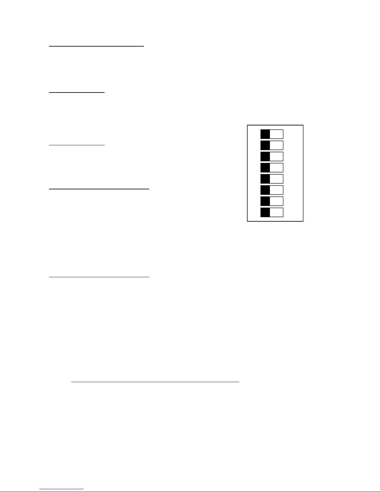
Dip Switch Settings for 100M unit
The following resistance alarm values may be set inside the combo meter.
The factory settings are represented in bold.
Foot Low sw1
.5M off (use this setting for 100K lower limit option meters)
.75M ON (US & IEC default)
Wrist Low sw2
.5M off (or for 100K lower limit option meters)
.75M ON (US & IEC default)
Foot High sw3 sw4 sw5
2M off off off
5M ON off off
10M off ON off
25M ON ON off
35M off off ON (IEC & CECC default)
50M ON off ON
75M off ON ON
100M ON ON ON (US default)
Wrist High sw6 sw7 sw8
2M off off off
5M ON off off
10M off ON off (US default)
25M ON ON off
35M off off ON (IEC & CECC default)
50M ON off ON
75M off ON ON
100M ON ON ON
1
2
3
4
5
6
7
8
Figure 1 Dip switch see table for settings
ON
A special 1000 megohm unit is also available. See below.
Static Solutions CT-8900 Combo Tester Instructions 7/22/2009
13
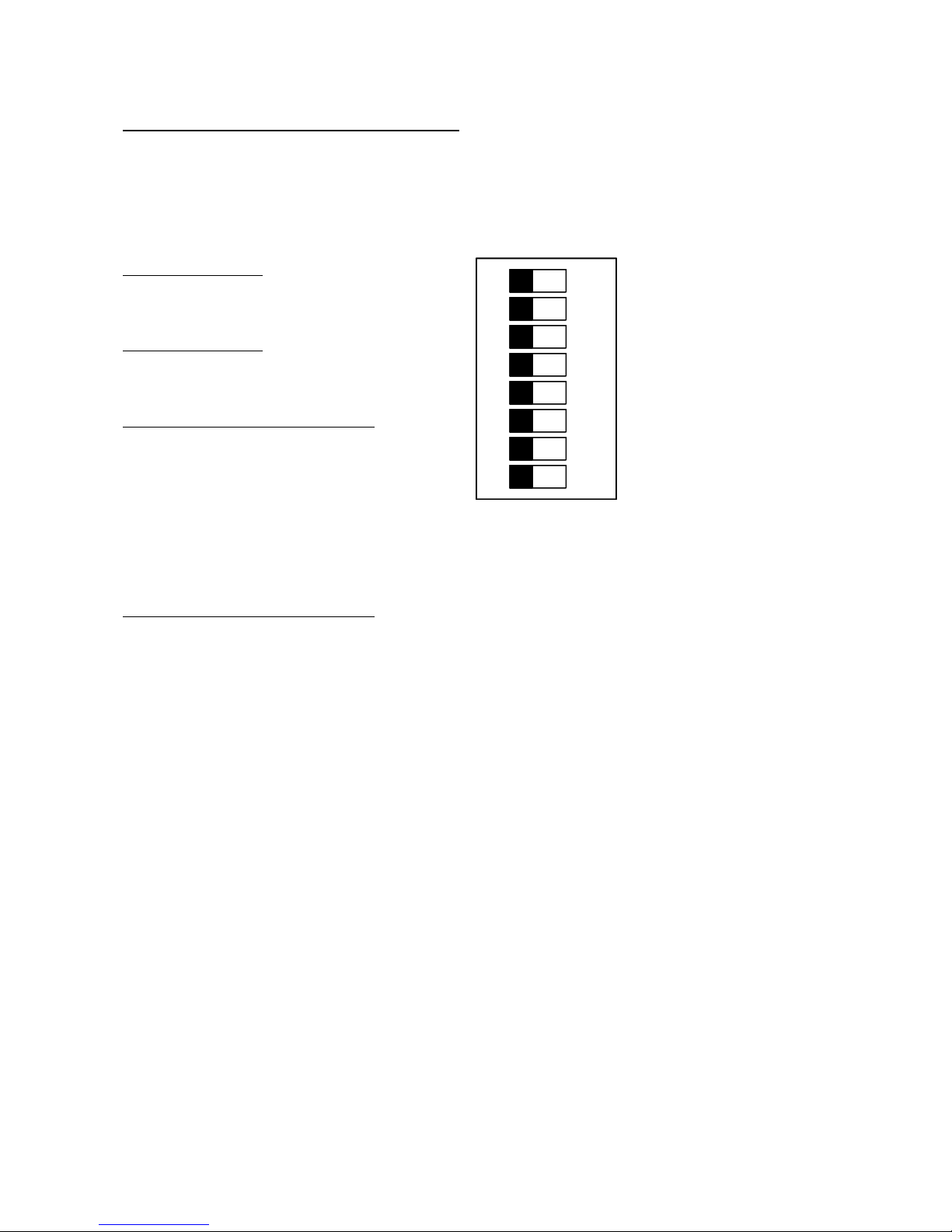
Dip Switch Settings for 1000M unit special unit
The following resistance alarm values may be set inside the combo meter.
The factory settings are represented in bold.
(For new dual range meter, remove jumpers W4 and W5. Add jumper W2)
Foot Low sw1
0 (none) off
.75M ON (default)
Wrist Low sw2
0 (none) off
.75M ON (default)
Foot High sw3 sw4 sw5
20M off off off
50M ON off off
100M off ON off
250M ON ON off
350M off off ON
500M ON off ON
750M off ON ON
1000M ON ON ON (default)
Wrist High sw6 sw7 sw8
20M off off off (default)
50M ON off off
100M off ON off
250M ON ON off
350M off off ON
500M ON off ON
750M off ON ON
1000M ON ON ON
1
ON
2
3
4
5
6
7
8
Static Solutions CT-8900 Combo Tester Instructions 7/22/2009
14
Door Relay
Units that are ordered with the a door-opening relay option will be equipped with two pigtail wires found on the right side of the unit.
There are two male bayonet type plugs attached to these wires. There are two unwired female jacks attached to these male plugs,
which can be attached to the open/close schematics on the door/bell circuit board (connected to the door mechanism). The relay in
the CT-8900 is a single throw, low voltage single pole normally open relay. When the user passes a test, the relay is activated and
remains closed for about 3 – 5 seconds after the user releases the test button. Units manufactured after 1/30/2006 have an
activation time adjust trimpot in them which can be used to adjust the door open time from about 1 – 9 seconds (see photograph
below).
The relay is rated .5 amps at 24 volts. It is illegal to introduce voltages greater than 24V into this unit, since shock hazards coluld
possibly occur. Please refer to the schematics of a footplate door opening mechanism. Substitute the two wire door wires for the
two-wire connection of the door foot-switch or hand-switch. The door in a facility has a second relay, usually of a higher voltage of
110 or 220VAC that allows voltage into the door electrical motor that opens and closes a door. This relay can be activated by a
press button, a proximity sensor, or a floor switch as in a super market. When a person passes the combo meter strap tests, the low
voltage relay in the combo meter is closed thus allowing current to pass into the higher voltage door relay and activate the motor in
the door. When the low voltage relay in the meter opens the reverse happens – the high voltage relay in the door is opened thus
stopping the door current, and the door closes.
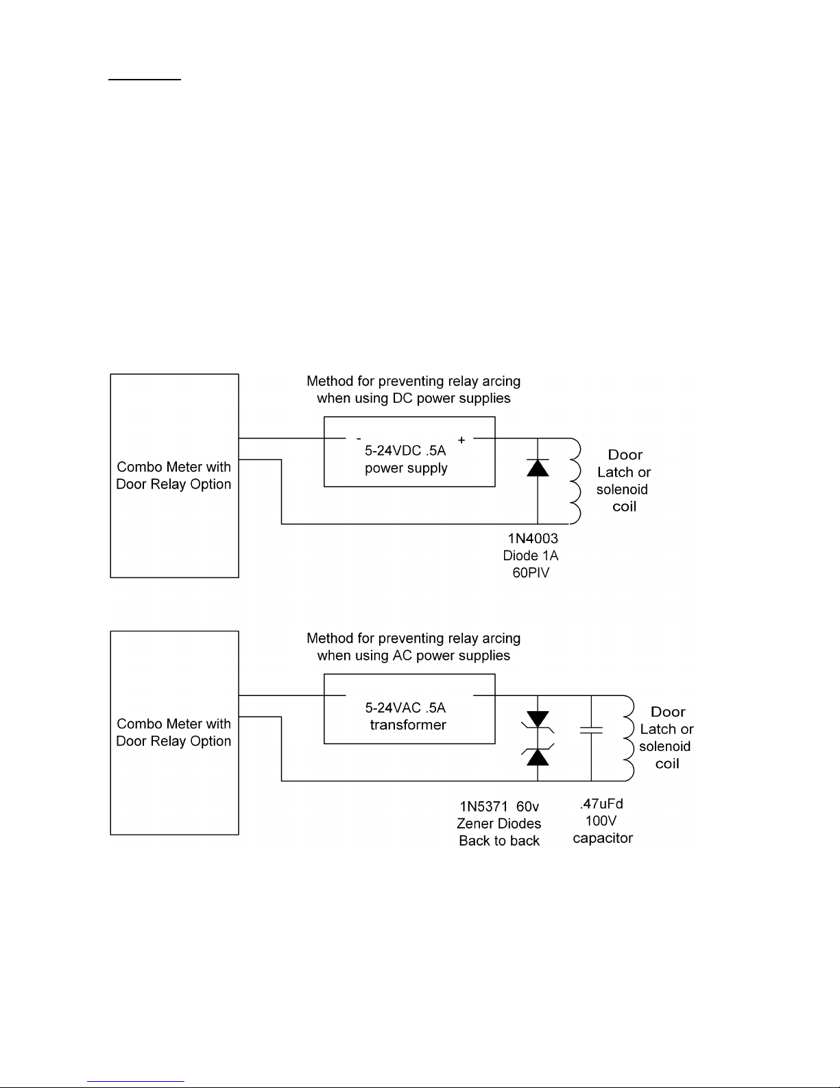
If the door relay contact is in series with a high current inductive load door latch such as a large solenoid or electromagnet, then
arcing can develop across the relay contact when the contact breaks the circuit, and shorten the relay life.
To prevent relay contact arcing if the contact current is DC, then a diode (such as a1N4003 or 1N4004) across the coil leads, with
cathode (band side) on the positive lead, may be wired across the contacts. The diode should have a PIV (peak inverse voltage)
rating of at least twice the DC voltage.
To prevent relay contact arcing if the contact current is AC, then two zener diodes back to back (band to band) may be wired across
the coil leads. The zener voltage should be at least twice the AC voltage. If running 24VAC (30VAC open load?), use two 60 volt
1N5371B zeners.
Static Solutions CT-8900 Combo Tester Instructions 7/22/2009
15
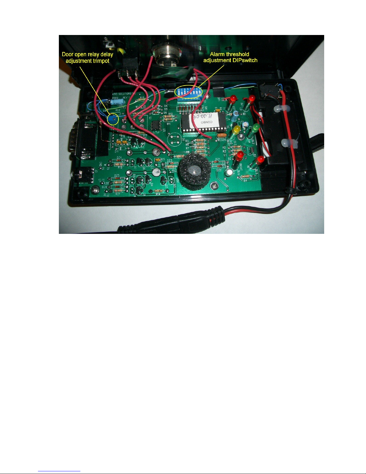
Set the “Door open relay delay adjustment trimpot” for the desired door opening time.
Static Solutions CT-8900 Combo Tester Instructions 7/22/2009
16

Multi-station hardware setup
Multiple meters may be connected to one computer via Static Solution’s numerous mult-istation options which include RS232 to
wired Ethernet converters, RS232 to wireless Ethernet converters, or multi RS232 port PCI cards in a computer. The specific
hardware installation and setup instructions of these options are included in separate manuals that are supplied with each of these
options.
Some of these options require the meter to be connected to a remote computer located quite some away, in which case the following
section applies.
Long distance wiring warning advisory
The following advisory only applies to meters that are connected to remote computers via long cables
:
As with any long distance wiring, proper grounding precautions should be considered. If the building in which the test stations are
located is improperly wired, or contains ground faults, or if the computer power supply is faulty, a shock hazard may exist.
If the tester is connected to the computer via a cable, and if the computer is located outside the local area, a voltage potential
difference could arise if the computer ground is not at the same voltage potential as the local ground near the test station. For
example, if the computer ground differed by 40 volts from a light switch cover plate on the wall located near the test station, and if an
employee touched the light switch while pressing the test station test button or standing on the test station foot plate, a mild electrical
shock hazard might arise. The tester has internal 20K limiting resistors to mitigate such a problem, but not eliminate it.
Thus it is advisable
not to locate the test station within reach of a metal object that might be grounded
and/or connect the meter ground (i.e. the power supply connector outer ground terminal ) to the local ground
When finished installing the test stations, be sure to test, and periodically retest, the voltage potential from the CT8900 combo tester
push button to the nearest local ground. If the building is properly wired, there should normally be no more than a few volts
difference.
Neither Static Solutions Inc, nor its distributors, accepts any liability for such hazards, as stated in the liability disclaimer.
Static Solutions CT-8900 Combo Tester Instructions 7/22/2009
17

SOFTWARE INSTALLATION GUIDE
Software Installation for First Time Installation of New Software
1. Close all open programs. If installation problems arise, then close anti-virus programs also.
2. Insert the CD into the CD reader.
3. If the CD does not start automatically, select "RUN" From the start menu and type: D:\setup and press enter. Follow
instructions.
4. If the following message is displayed, "A file being copied is older than the file currently on your system. It is recommended that
you keep your existing file. Do you want to keep this file? “, Select Yes. If the user is reinstalling this software due to a
computer error after already having input data, do not copy over the log.txt or names.txt files.
5. After installing the software, a small window will pop up asking if you want to check for newer versions on the internet. Note the
present version number. If the computer is connected to the internet, then you may press yes. Follow the instructions below for
“upgrading to a minor version change”.
6. To create an EsdTest program startup icon on your desktop as a shortcut, click Start, Programs and select the EsdTest icon in
the ESD Test folder to use as an icon to copy. Click on it, hold the left mouse button down, drag the icon onto the desktop,
press the Ctrl key to duplicate it, and release the mouse button. This should create icon on the desktop identical to the one in
the start menu. If you ever loose the start menu icon, you can also generate the desktop icon by using Windows Explorer to
locate the ESD Test folder on the hard drive, usually in the C:\EsdTest directory. Open it and right click on the EsdTest.exe file
icon. Select Create Shortcut in the menu, and then drag the newly created shortcut it onto your desktop.
Software installation for Upgrading to a Minor Version Change
When updating any software, it is advisable to first back up your present data. If all the data is contained in the c:\EsdTest directory,
then just back up this directory (as in step A below).
To get the latest software updates, run the EsdTest program and press the Help, “Check for software updates” menu item. This
should open an internet browser to www.EsdTest-SS.com
the website is newer than the present version, then:
1. Click on the top update link,
2. Download the update program
3. The unzip window should open
4. Modify the file destination folder box if necessary
5. Click Unzip
. Close the EsdTest program. If the version shown in the update link on
Software Installation for Upgrading to a Major Version Change
Follow these instructions to upgrade from ver 6 to ver 8, or from ver 7 to ver 8.
A - Backup everything.
1. Open Windows Explorer (not Internet Explorer). Either hold the Windows Logo key and press the E key, or click on the
MyComputer desktop icon.
2. If there are not 2 panes (columns) then click on the Folders icon so that you see 2 panes. The left pane should now say Folders.
3. Left click on the Local Disk (C:) drive item to expand it. All its folders should then be displayed beneath it.
4. Right click on the EsdTest folder and select Copy.
5. Right click on the Local Disk (C:) drive item and select Paste.
6. A new folder should have been created that says "Copy of EsdTest".
7. Left click on this new backup "Copy of EsdTest" folder and you should see all the files displayed in the right pane. There are 5
crucial ones: Names.txt, Log.txt, EsdTest.ini, GenReports.txt, and Netlist.txt. If these exist, then you can proceed to uninstall.
B - Uninstall old program
8. Close or minimize window explorer.
9. Click the Start icon on the lower left toolbar
Static Solutions CT-8900 Combo Tester Instructions 7/22/2009
18

10 Click Settings and/or Control Panel
11. Click Add/Remove Programs
12. Wait for all the programs to be displayed.
13. Left click on EsdTest
14. Left Click on Uninstall
15. Left click on OK.
16. The program should now have been uninstalled.
C - Install new program
17. Insert the new CD or run the new installation file
18. The CD should auto-boot and ask standard installation questions. If it does not auto-boot then open Windows Explorer again,
click on the CD drive, and click on Setup.exe. If you can not find Setup.exe then see if EsdTestVer8xxIS4.exe is there and click on it.
19. Once installed, a pop up window should appear and ask if you want to check the web for updates. Click yes which will open
Internet Explorer and take you to the update website, then click on the newest update. Updates can also be gotten later by opening
the EsdTest program and clicking on "Help", "Check for software updates".
20. If the EsdTest program is open then close it.
D - Copy the old data files (in Copy of EsdTest directory) back to the EsdTest directory
21. Open Windows explorer again (as you did in steps 1-3 above)
22. You should see all the directories in the left hand pane.
23. Left click on the "Copy of EsdTest" directory.
24. You should see all of its files in the right hand pane.
25. Hold down the Ctrl key and while holding it down left click once each on the following 5 files: Names.txt, Log.txt, EsdTest.ini,
GenReports.txt, and Netlist.txt.
26 Keep holding the ctrl key down. You should now see those 5 files highlighted in blue.
27. Keep holding the ctrl key down, and right click on one of the 5 files, and select copy.
28. Release the ctrl key.
29. Right click on the EsdTest directory in the left hand pane, and select paste.
30. If a message asks you if you want to over write a file, then make sure the file dates seem logical and then click yes.
E. - Check operation
31. Boot up the EsdTest program in the EsdTest directory. It should boot up and say ver 7.12 or higher. If you miss reading the boot
up logo, then just click Help About.
32. Check the names. They should be your old ones.
32. Run a report. It should show your old test data.
F. - Notes
For future updates, you will never have to do all this again, just click on Help "Check for software updates".
It is a good idea to occasionally back up everything anyway (as in steps 1-7).
STARTING THE PROGRAM
The EsdTest program may be automatically run upon computer boot-up by placing a program icon in the Programs Startup folder.
Click Start, Programs and select the EsdTest icon in the ESD Test folder to use as an icon to copy. Click on it and hold the left
mouse button down, drag the icon into the Programs Startup folder, press the Ctrl key to duplicate it, and release the mouse button.
This should create a copy of the program icon in the startup folder identical to the one in the start EsdTest menu.
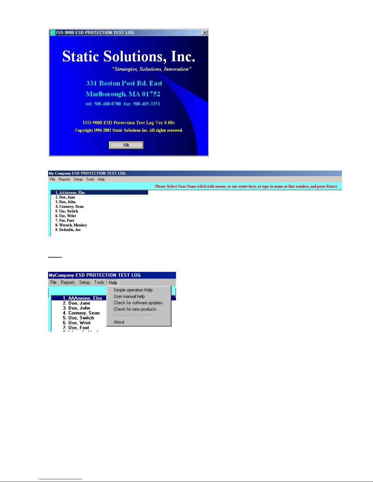
To start the program, manually click on the EsdTest icon in the Program Start menu or in the desktop. The program should begin
and appear as in the following example:
Static Solutions CT-8900 Combo Tester Instructions 7/22/2009
19
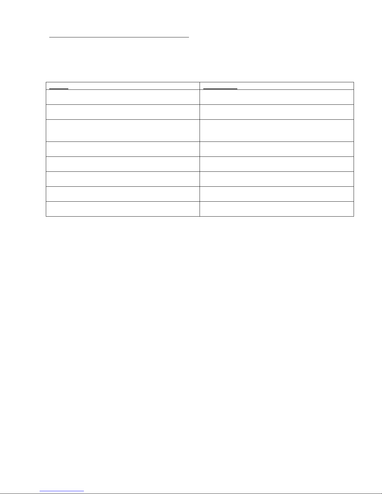
Help
Clicking the help item will give the following choices:
1. “Simple operation help” will list a help text file. This file (help.txt) can be modified with a word processor to give help
specific to your company.
2. “User Manual Help” will call Adobe acrobat (if it is installed) and display the user manual. This action requires the EsdTest
administrator’s password.
3. “Check for updates on website” will go to the EsdTest website if an internet connection and browser exist, and download
the latest EsdTest software. This action requires the EsdTest administrator’s password.
4. “Register this program” is no longer used.
5. “About” lists the EsdTest program version numberon the window shown at the top of this page.
If you have not yet plugged in a card reader (if purchased), then close the program, shut down the computer, and follow the
installation instructions below.
Static Solutions CT-8900 Combo Tester Instructions 7/22/2009
20
CARD READER INSTALLATION INSTRUCTIONS
For the following card readers, see the designated sections of this manual:
DEVICE SEE SECTION
Non RS232 Barcode readers (includes keyboard wedge and
USB barcode readers)
RS232 barcode readers (and RS232 Mag Stripe readers) Use
this setting even with RS232 to USB converter cables.
USB interface proximity card readers. This does NOT include
RS232 readers that have an RS232 to USB converter on them
that use virtual com port drivers
HID 5352 with Static Solutions RS232 converter CASI-RUSCO Weigand, HID 5352, HID RW-400ä, AWID SP-
HID RW-400 CASI-RUSCO Weigand, HID 5352, HID RW-400ä, AWID SP-
CasiRusco 94x, 97x Weigand, with Static Solutions RS232
converter
Awid Sentinel-Prox SP-6820 CASI-RUSCO Weigand, HID 5352, HID RW-400ä, AWID SP-
All other RS232 interface proximity card readers (for almost all of
the multi-station systems)
Keyboard Wedge and USB Bar Code Reader or Magnetic Stripe
Reader Installation
General RS232 Reader Installation
USB Reader Installation
6820 RS232 Reader Installation
6820 RS232 Reader Installation
CASI-RUSCO Weigand, HID 5352, HID RW-400ä, AWID SP6820 RS232 Reader Installation
6820 RS232 Reader Installation
General RS232 Reader Installation
Quick Setup
To set up In the employee selection window select
------------------------------- ---------------------------------------
USB Barcode reader* USB
USB Mag stripe reader* USB
Keyboard wedge Barcode reader* USB
Keyboard wedge Mag stripe reader* USB
USB proximity card reader USB
most RS232 proximity card readers General RS232**
most RS232 barcode readers General RS232**
most RS232 mag stripe readers General RS232**
old HID 5352 reader (see manual)
old HID RW-400ä reader (see manual)
old CASI-RUSCO 94x, 97x Weigand (see manual)
old AWID SP-6820 (see manual)
* NOTE: if some barcode or mag stripe
characters must be skipped
then use the following
To set up Select
------------------------------- -----------------------
USB Barcode reader Barcode-Mag (non RS232)**
USB Mag stripe reader* Barcode-Mag (non RS232)**
Keyboard wedge Barcode reader* Barcode-Mag (non RS232)**
Keyboard wedge Mag stripe reader* Barcode-Mag (non RS232)**
** NOTE: Also select
"Edit Reader Parameters"
to choose which characters
to use
Static Solutions CT-8900 Combo Tester Instructions 7/22/2009
21
Keyboard Wedge and USB Bar Code Reader or Magnetic Stripe Reader Installation
(i.e. unit is a keyboard wedge device that sends the badge number followed by a carriage return.)
1. NOTE: If your unit has a PS2 connector port for your keyboard, you will have to obtain a 5-din pin adapter from a local
electronics store. (Radio Shack)
2. Un-package the magnetic stripe reader or bar code reader and unravel cord.
3. Unplug your computer’s keyboard from the back of the CPU.
4. Plug the magnetic stripe reader or bar code reader (male end) into the keyboard socket in the back of the computer.
5. Plug the keyboard into the female terminal on the magnetic stripe reader or bar code reader. Attach the reader on the top
of the stand.
6. The magnetic stripe reader or bar code reader is now ready to use. Position the reader on TOP of the stand. Position the
CT-8900 directly below the reader so as the RS-232 does not protrude.
7. Turn computer on.
8. Install software
9. Read, “help files”.
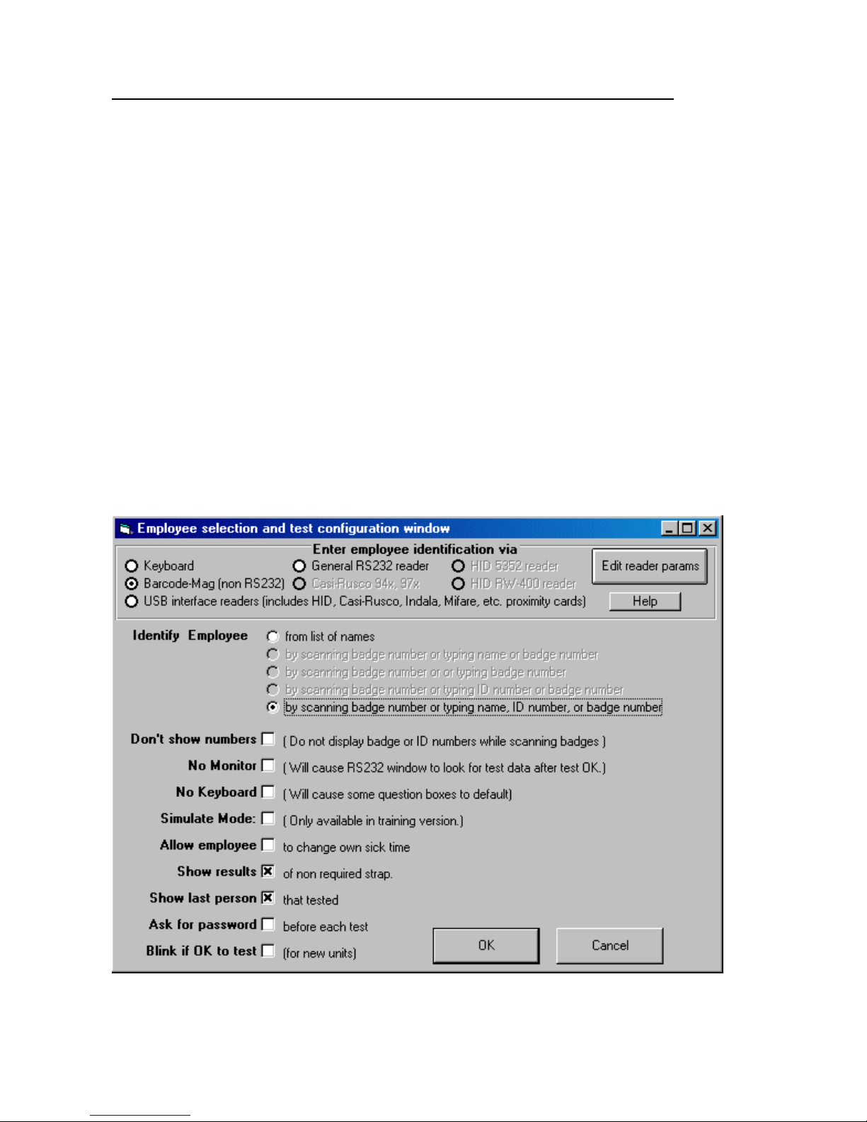
10. Open ESD program- Click “Set up”.
11. Click “Employee Selection Configuration”
12. Select Bar code/Mag reader. This is same setting if using magnetic stripe reader.
13. Select “by scanning badge number”
14. If you do not want the numbers to be displayed for safety reasons select the Don’t Show Numbers box.
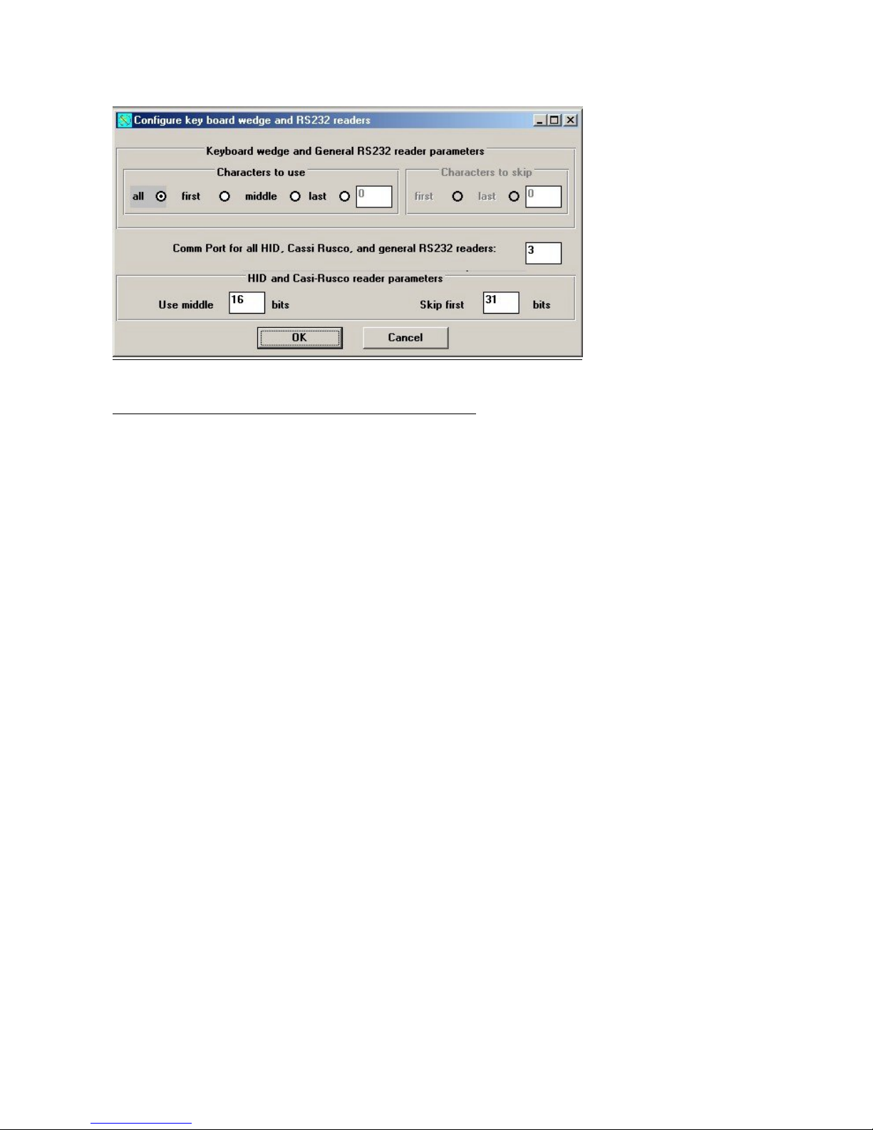
15. Press “Edit Reader parameters”.
16. Press “all” under Characters to use.
17. If you want to automatically enter new badges click all the 4 boxes in the unrecognized employee configuration window.
Static Solutions CT-8900 Combo Tester Instructions 7/22/2009
22
Trouble Shooting if Scanner Does Not Read Correctly
1. If your card- reader configuration is incorrect the card will not work. The reader must be programmed for your card
configuration. I.e. tracks 1,2,3 or 1 and 2, or 2 and 3 etc.
2. Try reversing your card around and offering the readable side on the reverse side. Pass card faster or slower. Clean with
water or alcohol if dirty.
3. Make sure the reader has been pre programmed to send a carriage return after a scan
4. Check characters to use configuration. If problems still continue send a sample card to Static Solutions.
Static Solutions CT-8900 Combo Tester Instructions 7/22/2009
23
 Loading...