

Page 1
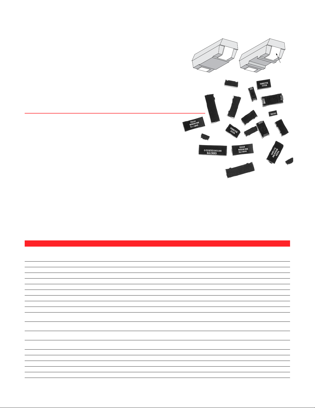
Surface Mount
Flexible
J-bend
Standard
pedestal mount
Recessed-base
mount
Power
RC Series: carbon composition (1/4 & 1/2 watt)
RC Series: ceramic composition (above 1/2 watt)
RF Series: metal film
RW Series: wirewound
RP Series: power film
RM Series: high voltage thick film
FEATURES
• Tolerance 1%, 5%, 10%, depending on construction
• Twelve wattage ratings
• Seven package sizes
• Two mounting designs to accommodate your soldering process
• Five power resistor technologies to optimize your operating performance:
1. Carbon and Ceramic composition for surge and low inductance
2. Metal film for high ohmic value and low T.C.
• Flexible J-bend terminations
• Working Temperature Range: -55°C to +150°C
Part Number (watts)* voltage 1% tol. 5% tol. 10% tol. 0.1Ω–1Ω 1Ω–10Ω 10Ω+ Withstanding 13” reels per reel
RC0S2CA––––– 0.25 250 — — 2.2Ω–5.6M — ±400 ±400 1000V 16mm 1500
RC0R5DB––––– 0.50 350 — — 2.2Ω–20M — ±400 ±400 1000V 24mm 1000
RW0S6BB––––– 0.6 50 0.010Ω–1K 0.005Ω–1K ±90 ±50 ±20 1000V 12mm 2500
RF0S8BA––––– 0.8 200 1Ω–5M — — ±100 ±100 1000V 12mm 2000
RW1S0BA––––– 1.0 50 0.005Ω–1K 0.005Ω–1K ±90 ±50 ±20 1000V 12mm 2000
RF1S0CA––––– 1.0 350 10Ω–1M 1Ω–10M — ±200 ±100 1000V 16mm 1500
RC1R0EA––––– 1.0 500 3.3-100K (10% tol only) -1300 1000V 32mm 750
RP1S3CA––––– 1.25 350 — 1Ω–1M — ±250 ±250 1000V 16mm 1500
RW1S5CA––––– 1.5 75 0.005Ω–1.5K 0.005Ω–1.5K ±90 ±250 ±250 1000V 16mm 1500
RP1S5CB––––– 1.5 350 — 1Ω–1M — ±250 ±250 1000V 16mm 1000
RP1R5CB–––––
RW2S0CB––––– 2.0 100 0.005Ω–5K 0.005Ω–5K ±90 ±50 ±20 1000V 16mm 1000
RW2R0CB–––––
RP2S0DA––––– 2.0 500 — 1Ω–1M — ±250 ±250 1000V 24mm 1000
RP2R0DA–––––
RW2S0DA––––– 2.0 100 0.005Ω–5K 0.005Ω–5K ±90 ±50 ±20 1000V 24mm 1000
RW2R0DA–––––
RP2R5DB––––– 2.5 500 — 1Ω–1M — ±250 ±250 1000V 24mm 1000
RW3R0DB––––– 3.0 200 0.005Ω–13K 0.005Ω–13K ±90 ±50 ±20 1000V 24mm 1000
RP3R0EA––––– 3.0 750 — 1Ω–1M — ±250 ±250 1000V 32mm 750
RW3R5EA––––– 3.5 350 0.005Ω–25K 0.005Ω–25K ±90 ±50 ±20 1000V 32mm 750
RM0R7EA––––– 0.75 2500 1KΩ–1000M 1KΩ–1000M — — ±50 1000V 32mm 750
3. Wire element for inrush current combined with low ohmic values.
Resistance values as low as 0.005Ω
4. Power film for high ohmic value and high wattage
5. High Voltage thick film for high voltage applications
SERIES SPECIFICATIONS
Power Maximum Resistance range Temp. Coefficient Dielectric Tape Size Quantity
*25°C ambient. E24 values standard; contact Ohmite for custom values.
(continued)
Page 2
100% 200% 300%
200
180
160
140
120
100
80
60
40
20
Temperature rise, ϒC
Percent Rated power
Alumina
Solder joint
FR4
Package limit hot spot temperature rise
100
Percent Rated Power
Ambient Temperature, ϒC
60
20
0
80
40
25 50 100 150750 125
0.02
500
400
300
200
100
Ohms
0.04 0.06 0.08 0.10
Typical TCR for
less than 0.1Ω SMD
resistors (PPM/°C)
Surface Mount Power
300
Temperature °C
Time (sec.)
Preheating
120 sec.
Soldering
Cooling
200
50
500 100 150 250200
0
250
100
150
60 sec.
10 sec.
PERFORMANCE DATA
Temp. cycle Load Life Immersion
(-55°C to 125°C, (1000 hours (260°C for Momentary
Construction 1000 cycles) at 25°C) 10 sec.) Overload
RC Carbon/Ceramic Comp. ±4.0%+.05Ω ±10.0%+.05Ω ±3.0%+.05Ω 6.3x rated power for 5 sec.
RF Metal Film ±0.5%+.05Ω ±0.5%+.05Ω ±0.1%+.05Ω 2x rated power for 0.1 sec.
RW Wirewound ±0.5%+.05Ω ±3.0%+.05Ω ±0.1%+.05Ω 5x rated power for 5 sec.
RP Power Film ±3.0%+.05Ω ±5.0%+.05Ω ±0.5%+.05Ω 2x rated power for 0.1 sec.
RN Wirewound, Non-inductive ±0.5%+.05Ω ±3.0%+.05Ω ±0.1%+.05Ω 5x rated power for 5 sec.
ALL models: Leaching (260°C Solder immersion, 60 sec.)....................... No visible leaching
Thermal Shock (Units at -55°C, then rated power applied).. No mechanical damage
Flammability ......................................................................... UL Material rating, UL94V0
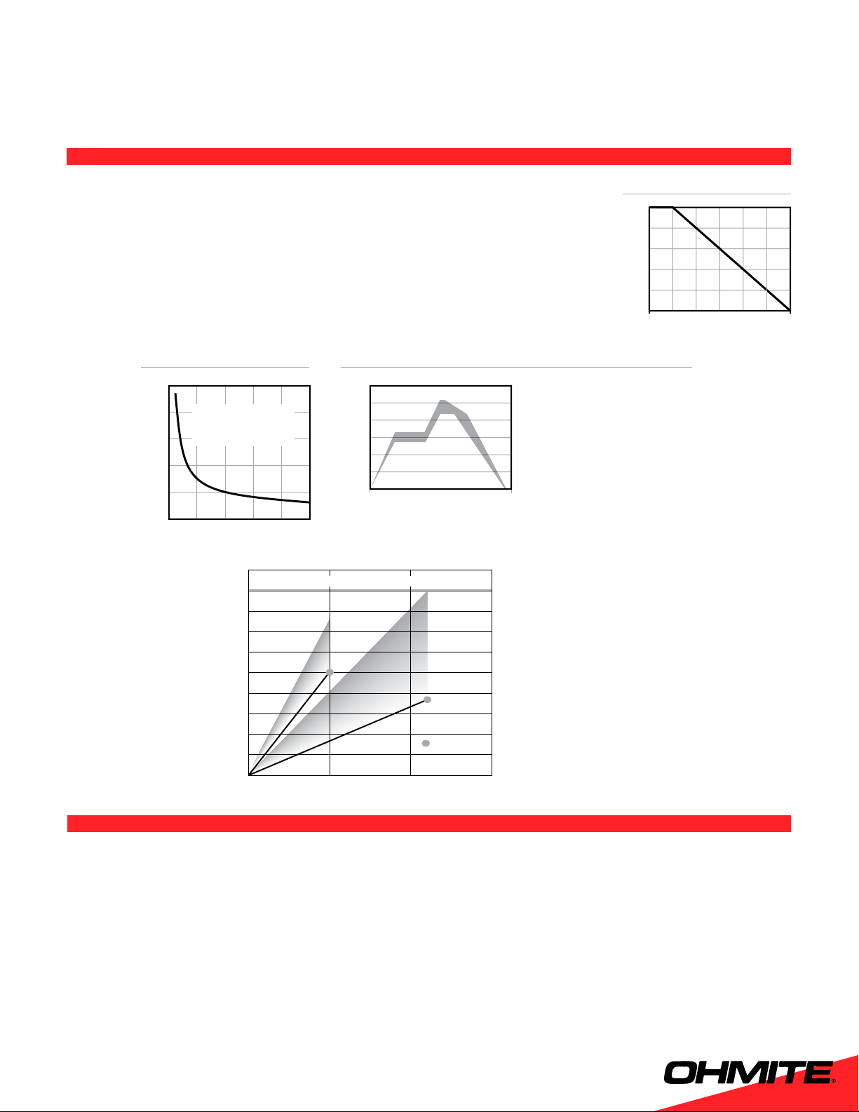
Derating
TCR
Recommended Solder Profile
Preheating: 145°C ±15°, max. 120 sec.
Soldering: min. 220°C, max. 60 sec.
Max. Temp.: 260°C ±5°, 10 sec.
(RC only: 250°C ±5°, 3 sec.)
The temperature rise graph
data was obtained by a
selection of test substrate
size and trace width for
each resistor size to limit
operating temperatures to
safe values.
The operating temperature
safe rises are either 100°C
substrate temperature rise
or 180°C package hot spot
temperature rise at 25°C
ambient.
FR4: 0.062 in. thick; 0.062
in. traces
Alumina: 0.040 in. thick;
0.010 in. traces
Molding material rated at
205°C continuous.
RC SERIES ONLY C. Cautions
A. Heat Treatment
110°C ±10°C
15 hours
RC SERIES: BAKE PROCEDURE
B. Frequency of
heat treatment
1 time only
Solderability: may be affected due to oxidization of lead wire
Resistance value: some units may not completely recover to origi-
nal value.
Soldering heat: some treated product may have substantial resis-
tance change during soldering operation. It is recommended that
parts be tested to evaluate soldering heat effects.
Page 3

Surface Mount Power
J
I
C
B
K
=0.006 Ref.
D
A
E
G
H
Note 1
F
=0.005 ±.001
Note 2
L
O
M
P
N
Recommended
for glue dot
application
A
0.795*
20.2
min.
0.512 ±.008
13.0 ±.200
C
B
1.973
50
min.
0.059*
1. 5
min.
Full
Radius
Tape Start Slot
Measured
at Hub
0.098 /
2.5
min. width
0.394 /
10
min. depth
DIMENSIONS
(in./mm)
Packages A B C D G I J L M N O P
BA (in.) 0.246±.020 0.136±.005 0.133 REF 0.110±.010 0.047 ±0.020 0.054±.012 0.136±.005 0.150 0.346 0.098 0.126 0.050
(mm) 6.248±.508 3.454±.127 3.378 REF 2.794±.254 1.194 ±0.508 1.372±.305 3.454±.127 3.81 8.79 2.49 3.20 1.27
CA (in.) 0.394±.020 0.159±.005 0.156 REF 0.220±.010 0.062 Nom. 0.064±.012 0.159±.005 0.256 0.524 0.134 0.126 0.060
(mm) 10.008±.508 4.039±.127 3.962 REF 5.588±.254 1.575 Nom. 1.626±.305 4.038±.127 6.50 13.31 3.40 3.20 1.52
CB (in.) 0.407±.020 0.226±.005 0.222 REF 0.260±.010 0.062 Nom. 0.084±.012 0.222±.005 0.276 0.537 0.131 0.126 0.093
(mm) 10.338±.508 5.74±.127 5.639 REF 6.604±.254 1.575 Nom. 2.134±.305 5.639±.127 7.01 13.64 3.33 3.20 2.36
DA (in.) 0.455±.020 0.240±.005 0.236 REF 0.260±.010 0.062 Nom. 0.115±.012 0.226±.005 0.317 0.585 0.134 0.155 0.093
(mm) 11.557±.508 6.096±.127 5.994 REF 6.604±.254 1.575 Nom. 2.921±.305 5.740±.127 8.05 14.86 3.40 3.94 2.36
DB (in.) 0.625±.020 0.273±.005 0.268 REF 0.417±.010 0.062 Nom. 0.115±.012 0.226±.005 0.474 0.742 0.134 0.155 0.093
(mm) 15.875±.508 6.934±.127 6.807 REF 10.592±.254 1.575 Nom. 2.921±.305 5.740±.127 12.040 18.85 3.40 3.94 2.36
EA (in.) 0.811±.020 0.273±.005 0.268 REF 0.572±.010 0.093 Nom. 0.115±.012 0.273±.005 0.611 1.000 0.195 0.155 0.093
(mm) 20.599±.508 6.934±.127 6.807 REF 14.529±.254 2.362 Nom. 2.921±.305 6.934±.127 15.52 25.4 4.95 3.94 2.36
BB (in.) 0.202±.010 0.10±.010 0.095 REF 0.079±.010 0.050 Nom. 0.065±.012 0.135±.005 0.078 0.328 0.125 0.126 0.026
(mm) 5.140±.508 2.54±.127 2.41 REF 2.00±.254 1.280 Nom. 1.640±.305 3.420±.127 1.98 8.33 3.18 3.20 0.66
Note 1: Packages BA and CA are only available with a pedestal base. Packages CB and DA are available in either pedestal or recessed base. Packages DB and EA
are only available in a recessed base.
Note 2: Test point is .020 above PCB.
Note 3: Tape and reel dimensions per EIA 481 A except “EA” size which is 12 mm component pitch versus 16mm pitch.
Package Outline Dimensions PC Board Land Pattern
Land pattern dimensions are for reference only
Reel Dimensions
Size A nom. B C max. Quantity
12mm 13” 0.488" +0.078, –0.00 0.724" 2000 pcs. BA or
16mm 13” 0.646" +0.078, –0.00 0.882" 1500 pcs. CA or
24mm 13” 0.961" +0.078, –0.00 1.196" 1000 pcs. DA or DB
32mm 13” 1.276" +0.078, –0.00 1.52" 750 pcs. EA
All reels are compatible with major pick-and-place machines
and made in accordance with EIA 481 A (except EA size,
which is 12mm component pitch versus 16mm pitch).
12.4mm +2.0, –0.0 18.4mm 2500 pcs. BB
16.4mm +2.0, –0.0 22.4mm 1000 pcs. CB
24.4mm +2.0, –0.0 30.4mm
32.4mm +2.0, –0.0 38.4mm
(continued)
Page 4

Component type
R = resistor
Component Modifier
C = carbon/ceramic
composition
F = film
P = power film
W = wire
N = wirewound, non-inductive
Wattage
Examples:
1S3 = 1.25W
2S0 or 2R0 = 2.0W
3R5 = 3.5W
Type of Base
S = standard
R = recessed
Package
B = 12mm
C = 16mm
D = 24mm
E = 32mm
Package Modifier
A, B sequential
Resistance Value
R = Decimal
K = 1,000
M = 1,000,000
Tolerance
F= 1%
G= 2%
H= 3%
J= 5%
K=10%
Examples:
R249 = 0.249 ohms
24R9 = 24.9 ohms
2K49 = 2,490 ohms
T = Tape
and Reel
(optional)
E = RoHS compliant
Available Jan. 2006
Surface Mount Power
ORDERING INFORMATION
(For example, the part
number shown is a wirewound resistor, 3.5 watt,
recessed base, 32mm tape
size, first case size [A],
1000 ohms 1% tolerance.)
Standard Part Numbers for Surface Mount Power Resistors
Wirewound
Package style
Base: standard
or recessed
Wattage
BA CA CB CB DA DA DB EA BB EA
S S S R S R R R S R
1.0 1.5 2.0 2.0 2.0 2.0 3.0 3.5 0.6 1.0
Part No.
Prefix
Suffix Tolerance suffix: F = 1% J = 5% K=10%
Ohmic value
RW1S0BA–––
RW1S5CA–––
RW2S0CB–––
RW2R0CB–––
RW2S0DA–––
RW2R0DA–––
RW3R0DB–––
RW3R5EA–––
0.005 –––R005– J J F/J
0.010 –––R010– F/J J J F J J J F
0.015 –––R015– F/J J F
0.020 –––R020– J J F J J F
0.025 –––R025– J
0.027 –––R027– J
0.030 –––R030– F J J J F
0.033 –––R033– J
0.036 –––R036– J
0.050 –––R050– F/J J J F J J F
0.056 –––R056– J
0.075 –––R075– J F
0.080 –––R080– J J
0.100 –––R100– F/J J J F J J J F
0.150 –––R150– J J J
0.200 –––R200– J J J
0.220 –––R220– J
0.240 –––R240– J J F
0.300 –––R300– J J
0.330 –––R330– J
0.400 –––R040– J
0.400 –––R400– J
0.470 –––R470– J J J F
0.500 –––R500– J J J J
0.750 –––R750– J F
1.00 –––1R00– F/J J J J J F
2.00 –––2R00– F
RW0S6BB–––
Wirewound
Package style
Base: standard
or recessed
Wattage
BA CA CB CB DA DA DB EA BB EA
S S S R S R R R S R
1.0 1.5 2.0 2.0 2.0 2.0 3.0 3.5 0.6 1.0
Part No.
RC1R0EA–––
Prefix
Suffix Tolerance suffix: F = 1% J = 5% K=10%
Ohmic value
RW1S0BA–––
RW1S5CA–––
RW2S0CB–––
RW2R0CB–––
RW2S0DA–––
RW2R0DA–––
3.30 –––3R30– K
4.70 –––4R70– K
5.00 –––5R00– F
5.60 –––5R60– J
6.80 –––6R80– K
7.50 –––7R50– J F
10.00 –––10R0– J J J F K
15.00 –––15R0– J J F K
20.00 –––20R0– J
22.00 –––22R0– F K
24.90 –––24R9– F
33.00 –––33R0– F K
36.00 –––36R0– F
47.00 –––47R0– J J F K
50.00 –––50R0– J
51.00 –––51R0– J
68.00 –––68R0– K
82.00 –––82R0– J
100.00 –––100R– J F K
120.00 –––120R– J
180.00 –––180R– J
300.00 –––300R– J
470.00 –––470R– J
1K –––1K00– J K
4.7K –––4K70– J
5K –––5K00– J
RW3R0DB–––
RW3R5EA–––
RW0S6BB–––
RC1R0EA–––
35
 Loading...