

Page 1
AE
SERVICES
STANDARD
AUTTIORISATION
SECTION
SERVICE
REVTSION:-
DATE:
14.03.2001
1
PROCEDURE
7
ЗЕ
Tec 4 Vaporizer
Section
1
Service
Manual
Page 1 of
Revision
18
7
Page 2

Page 3
AE
SERVICES
1.
Introduction
‘The
standard
Disassembly
Thorough
Inspection
Renewal
Lubrication
Tactile
Checks
Te-calibration
Unless
cleaning.
for
of
Wicks,
Tests.
of
the
otherwise
service
of
delivered
as
ol a Tec 4 Vaporizer
components
damage
and
wear.
Seals
and
concentration
necessary.
stated,
the
SECTION
RVICING
shall
as
required,
damaged
procedures
or
worm
under
closely
which
1
consist
components
follow
of
the
following:
as
defined
conditions
are
applicable
required.
and
to
all
Tec 4 vaporizers.
At
cach
stage
of
Service
generated
Record
by
the
testing,
AEOF-10.7.1/3
lascr
the
operator
shall
(filled-in
reltaciometer
and
CONTROLLED
record
the
by
hand)
and
laptop
computer.
DOCUMENT
test
results
on
the
on
Test
Certificate
Tee 4 Vaporizer
Service
Section
Manual
Page
20118
Revision
7
Page 4

Page 5
AE
SERVICES
2
21
211
ZII
2112
2.1.2
SERVICE
Draining
Method
Draining
a)
Drain
liquid
tilting
Drying-Out
a)
Mount
b)
Passa
hour
PROCEDURES
and
Drying
1
alt
the
free
can
be
scen
the
vaporizer
the
vaporizer
flow
of
5 litres/minute
until the
wicks
Alternatively:
a)
Block
the
outlet
of
the
vaporizer
flow)
Method
2
for
drain
one
hour
Out
liquid
from
the
in
the level
slightly
on
tube.
forwards,
the
test
air
have
dried
the
vaporizer,
to a vacuum
until the
vaporizer
vaporizer
Note.
stand
or
oxygen
out.
Lixhaust
tum
system
until
Draining
and
turn
through
to
the
dial
(between
îs
dry.
only a very
can
be
assisted
the
dial
to
its
the
vaporizer
suitable
to
its
maximum
10
and
a
gas
30
small
amount
by
maximum
for
scavenging
setting
litrestminute
of
carefully
setting.
at
Icast
one
system
and
connect
negative
FARA!
212
Agent
Draining
b)
e)
Drying
a)
b)
©).
Recovery
a}
Connect
into
the
Open
To
slightly
Ensure
Open
measuring
Condenser
Transfer
future purity check.
the
the
the
drain
clamp
screw.
the
drain
ensure
that
until
Out
that
the
drain
cylinder,
Record
the
Winchester
Condensers
vaporizer
port
screw
all
liquid
the
Condenser
valve,
to
of
the
and
liquid
can
and
Record
Form
agent
into
(Refer
bottle
in
the
vacuum
keyed
sct
the
is
drained
no
longer
is
switched
drain
the
system
filler
assembly
dial
to
its
maximum
from
the
be
scen
flowing
‘OFF.
olf
all
agent
quantity
of
anaesthetic
AEOF-10.6.1/1
the
appropriately
(0
TEST
the
designated
fabelled
EQUIPMENT
quarantine
by
inserting
and
vaporizer,
into the
into the
brown
drug
clamping
mark.
it
«itt
the
glass
appropriately
agent
recovered
Winchester
MANUAL
arca
of
the
Section
drug
specific
in
vaporizer
adaplor
position
with
farward
Mask
labelled
on
the
bottle
for
11).
Store
cupboard.
Teo 4 Vaporizer
Section
|
Service
Manual
[7
ROLLED
DOGUNENT
一
—
Page 3 of
Revision
18
7
Page 6

Page 7
AE
SERVICES
ENFLURANF
Close
the
Turn
on
the
out
of
the
‘Tum
off
the
NOTE:
may
In
be
set
ISOFLURANE
Close
the
pipe
“T
connection
aitting
Öpen
d)
Switch
(the
clapse
©)
During
pressure
action
£
_If
gun
the
on
green
in
drying-out
indicates
must
the
who
will
CONDENSFR
valve
on
the
outlet
drying-out
pump
system.
drying-out
order
to
in
the
pump,
speed
red-light
CONDENSER
valve
on
the
outlet
on
the
(0
force
out
any
outlet
valve
and
the
Condenser
lamp
will
be
illuminated)and
order
to
permit
monitor
thal
ice
be
taken
to
restore
specified
pressure
take
the
required
ONLY
lo
the
at
the
close
up the
Condenser
Condenser
time-switch
the
and
open
to
force
drain
valve,
thawing-out
position
ONLY
to
the
condenser
Condenser
remaining
re-fit
by
turning
the
"I"
the
inlet,
water
piece.
and
open
and
blow
[rom
switch
to
the
the
allow a period
the
correct
the
is
causing a restriction
is
operating
Condenser
the
Condenser's
exceeded,
pressure
inform
temperature
gauge.
to
optimum
the
action.
the
drain
valve.
any
temaining
and
open
the
process,
the
drain
through
the
water
outlet
the
heater
valve.
Detach
Condenser
system
cooling
the
Service/Test
position,
of
45
minutes
to
be
An
increase
gas
low,
operating
to
achieved.
in
and
that
condition.
Supervisor,
valve.
switch
the
using
an
22
2)
THEN:-
h)
i)
고
Recordthe
Blankofl'iheinict
Connect
Turn
dry out
quantity
the
vaporizer
the
dial
to
as
follows:
of
dricd-out
pori
with a plastic
to
the
maximum
the
evacuation
Halothane
Enflurane
vaporizers
on
AEQF-10.6.1/1
plug
system
calibration
/
Lsofluranc
mark
and
allow
the
40
minutes
30
minutes
vaporizers
to
Max.
Max
Tec 4 Vaporizer
Section
Service
Manual
Page 4 of
Revision
18
7
Page 8

Page 9
AE
SERVICES
23
24
25
INSPECTION/CITECK
With
the
exception
Interlock
carefully
vaporizer
Visually
damaged
Ensure
Block,
remove
using a cloth
examine
or
wom
that
the
satisfactorily
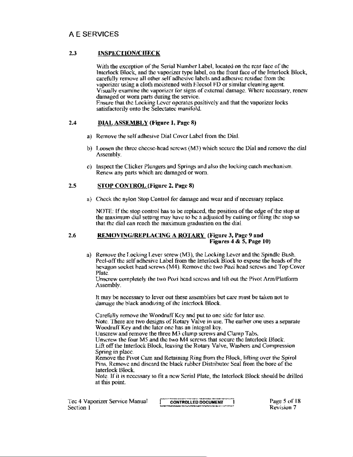
DIAL
ASSEMBLY
Remove
Loosen
the
the
three
of
the
and
the
all
other
moistened
the
vaporizer
parts
during
Locking
onto
the
Selectatec
(Figure
self
adhesive
cheese-head
Assembly.
Inspect
Renew
Check
NOTE:
the
that
the
Clicker
any
parts
DP
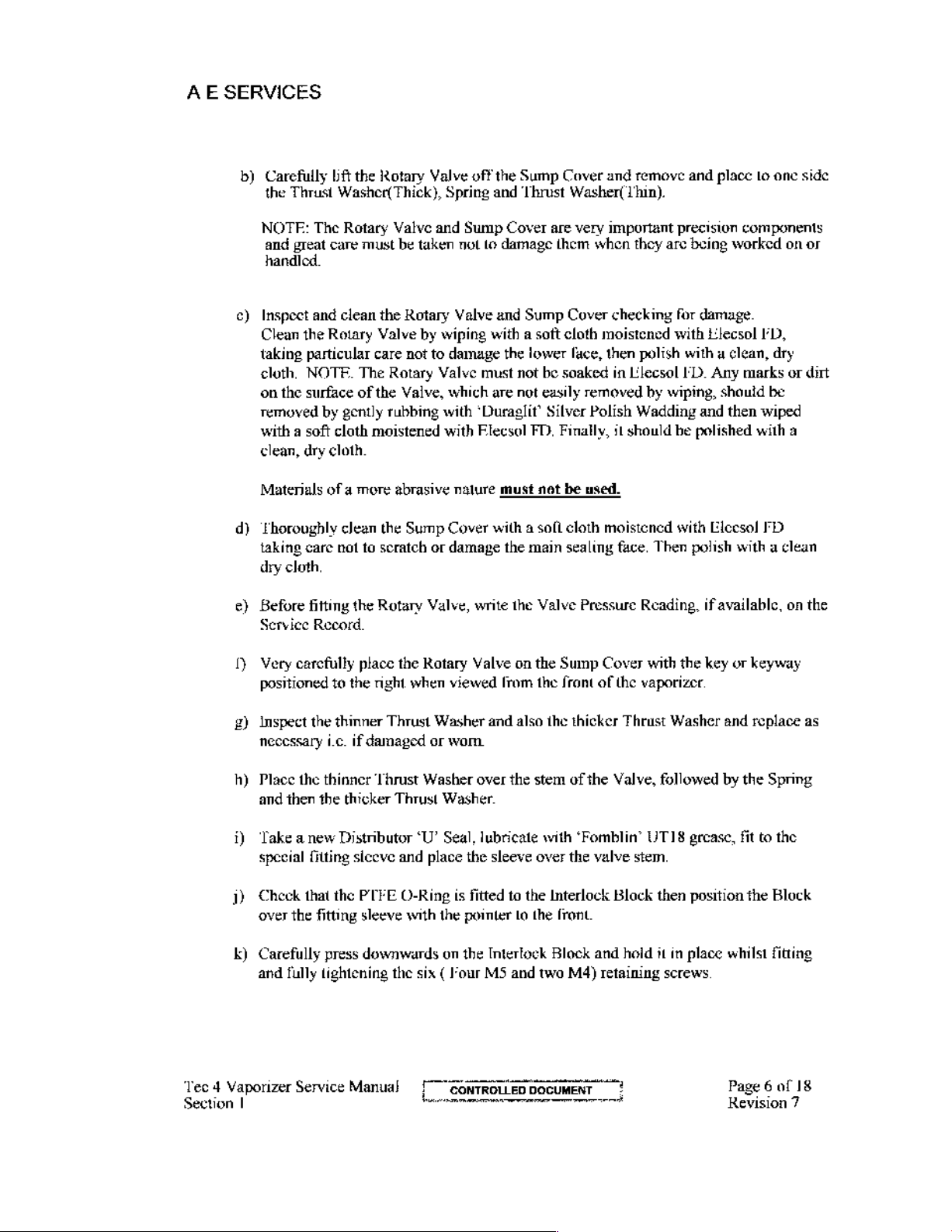
CONTROL
the
nylon Stop
If
the
stop
maximum
the
dial
dial
can
Plungers
which
arc
(Figure
Control
contro!
setting
reach
the
Serial
Number
vaporizer
self
Lever
type
label,
adhesivo
lor
the
operates
labels
with
Elecsol
signs
service.
positively
manifold,
1,
Page
8)
Dial
Cover
Label
screws
and
damaged
2,
for
has
to
may
maximum
(M3)
Springs
or
worn
Page
8)
damage
be
replaced,
have
to
he a adjusted
graduation
Label,
located
on
the
and
adhesive
ED
or
of
external
and
from
the
which
secure
and
also
the
and
wear
and
the
position
by
on
the
on the
font
similar
damage.
that
rear face
face
of the
residue
cleaning
Where
the
vaporizer
Dial
the
Dial
locking
catch
if
necessary
of
the
edge
culling
dial
or
of
the
Interlock
from
Block,
the
agent.
necessary,
renew
locks
and
remove
the
mechanism.
replace
of
the
stop
filing
the
stop
so
dial
at
2.6
REMOVING/REPLACING A ROTARY
Remove
Peel-off
hexagon
Plate.
Unscrew
Assembly.
It
may
damage
Carefully
Note.
Woodrult
Unscrew
Unscrew
Lift
off the
Spring
Remove
Pins,
Remove
Interlock
Note.
at
this
Tec 4 Vaporizer
Section
1
Service
the
Locking
the
self
adhesive
socket
head
completely
be
necessary
the
black
anodizing
remove
There
Key
and
the
the
are
two
and
the
remove
four
MS
Interlock
in
place
the
Pivot
Cam
and discard
Block.
If
it
is
necessary
point.
Manual
Lever serew (M3),
Label
from
the
screws
the
to
Woodruff
designs
the
Block,
(M4).
two
Pozi
lever
out
of
the
of
Rotary
later
one
three
M3
and
the
two
leaving
and
Retaining
the
black rubber
to
fit a new
[CONTROLLED
——
Remove
head
screws
these
assemblies
interlock
Key
and
Valve
has
an
integral
clamp
M4
serews
the
Rotary
Ring
Serial Plate,
(Figure
3,
Page 9 and
Figures 4 &
the
Locking
interlock
the
Block
two
Pozi
and
lift
but
Lever
head
out
care
Block.
put
to
one
side
for
in
use.
The
earlier
key.
screws
DOCUMENT
and
Clamp
that
secure
Valve,
from
the
Distributor
the
the
Washers
Block,
Seal
Interlock
1
5,
Page
and
the
to
expose
serews
the
Pivot
must
be
taken
later
use.
one
Tabs.
Interlock
and
lifting
over
from
the
Block
10)
Spindle
the
Bush.
heads
of
and
Top
the
Cover
Ann/Platform
not
to
uses a separate
Biock.
Compression
the
Spirol
bore
of the
should
be
drilled
Page 5 of
Revision
18
7
Page 10

Page 11
AE
SERVICES
b)
Carefully
the
Thrust
bft
the
Rotary
Washer(Thick),
Valve
off
Spring
the
Sump
and
Thrust
Cover
and
remove
Washer(
hin).
and
place
lo
one
side
NOTE:
and
The
great
handled.
¢)
Inspect and
Clean
the
taking
cloth,
on
removed
with a soft
clean,
Materials
d)
taking
dry
e)
Before
Service
1)
Very
particular
NOTE.
the
surface
by
dry
of a more
Thoroughly
care
cloth
fitting
Record,
carefully
positioned
Rotary
care
clean
Rotary
Valve
must
the
Valve
care
The
Rotary
of
the
gently
rubbing
cloth
moistened
cloth
abrasive
clean
the
nat
to
scratch
the
Rotary
place
to
the
right
and
be
taken
not
Rotary
not
Valve,
Valve
by
wiping
to
damage
Valve
which
with
with
nalure
Sump
Cover
or
damage
Valve,
the
Rotary
when
viewed
Sump
Cover
are
lo
damage
and
with a soft
the
must
are not
‘Duraglit’
Flecsol
must
with a sofi
the
write
the
Valve
[rom
them
Sump
lower
not
be
easily
Silver
FD,
Finally,
net
main
Valve
on
the
the
Cover
cloth
soaked
be
cloth
sealing
Sump
frant
very
important
when
they
checking
moistened
face,
then
polish
in
L'lecsol
removed
Polish
used.
by
Wadding
il
should
moistencd
face.
Then
Pressure
Reading,
Cover
of
with
the
vaporizer.
precision
are
being
for
with
components
worked
damage.
Elecsol
with a clean,
FD.
Any
marks
wiping,
be
should
and
then
polished
with
Eleesol
polish
with a clean
if
available,
the
key
or
keyway
with
on
or
FD,
dry
or
dirt
be
wiped
a
FD
on the
£)
Inspect
necessary
h)
Place
and
1)
‘Take
special
j)
Check
over
k)
Čarefully
and
‘Tec 4 Vaporizer
Section
|
the
ie.
the
thinner
then
the
anew
fitting
that
the
fitting
press
fully
lightening
Service
thinmer
Distributor
the
Thrust
if
damaged
Thrust
thicker
or
Washer
Thrust
‘U’
siceve
and
PTFE
O-Ring
sleeve
with
place
downwards
the
six ( Four
Washer
wom.
Washer.
Seal,
is
the
on the
Manual
and
also
the
over
the
stem
lubricate
the
sleeve
fitted
pointer
Interlock
MS
with
over
to
the
Interlock
to
the
Block
and
two
thicker
of
the
Valve,
Thrust
‘Fomblin’
the
valve
stem.
Block
front
and
hold
M4)
retaining
Washer
followed
UTI8
gecasc,
then
position
it
in
place
screws
and
replace
by
the
fit
the
whilst
Page 6 of
Revision
as
Spring
to
the
Block
fitting
18
7
Page 12

Page 13
AE
SERVICES
1)
Ensure
Grease
Rotary
that
the
Valve
adequately
Secure
evenly
Tin-up
m)
Fnsute
the
tightening
keyways
thal
assemblies
Secure
that
n)
Check
Plungers
M3
0)
Install
Knob
Install
Note
Inspection
the
there
is
that
and
screws.
the
Bush
the
that
the
there
is
sufficient
Pivot
Cam
as
required
spindle
lubricated
Retaining
there
and
assemblies
minimum
Spring
Springs
Lop
on
Lock/Unlock
Lock/Untock
stage.
into the
with
Fomblin
Ring
with
down
in
position.
in
Cam
and
is
sufficient
re-fit
the
Interlock
with
clcarance
is
in
position
are
in
Cover
Plate,
the
Locking
Lever
Knob
Label
Fomblin
Interlock
UT18
with
Fomblin
Block.
UTI8
the
three
Rotary
Valve
Fomblin
UT18
assembly.
two
M4
screws,
belween
then
re-fil
position
securing
and
re-fit
with
Spindle.
and sceure
may
be
fitted
grease
grease
M3
screws
then
grease
tightening
the
Pivot
Stop
two
with
on
UTI8
grease
Ensure
that
and
fit
and
fit
the
Woodrull
on
the
down
Bearings
Release
the
Dial
Assembly,
M4
screws,
one
M3
screw.
after
the
the
Button.
inal
Slip
Ring
and
then
the
retaining
into the
Clamp
Interlock
Tabs,
Key
Platform
in
position
and
Pivot
Check
sccuring
Install
the
Test
ai
and
replace.
fit
over
the
Ring
is
Black.
carefully
and
Pivot
but
and
Arm
ensuring
Arm.
that
Clicker
with
three
Lock/Unlock
the
Final
‘Tee 4 Vaporizer
Section
1
Service
Manual}
Page 7 of
Revision
18
7
Page 14

Page 15
AE
SERVICES
Figure 1 Dial
Assembly
Tec 4 Vaporizer
Section
I
Service
Manual
|
CONTROLLED
Figure 2 Dial
DOCUMENT
and
Stop
Control
Page 8 of
Revision
18
7
Page 16

Page 17
AE
SERVICES
E
.
+
n
品
i
na
Tec 4 Vaporizer
Section
|
Service
Manual | CONTROLUFO
DOCUMENT";
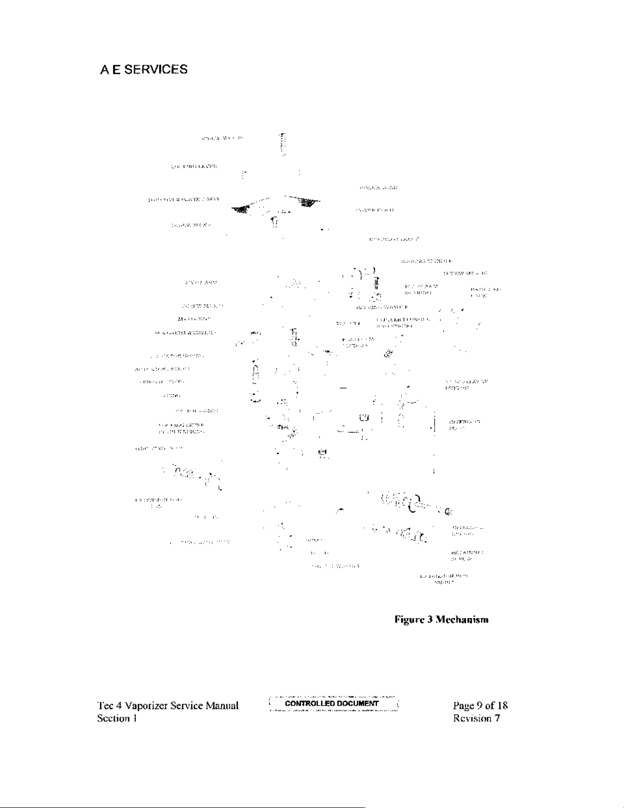
Figure 3 Mechanism
Page 9 of
Revision
18
7
Page 18

Page 19
AE
SERVICES
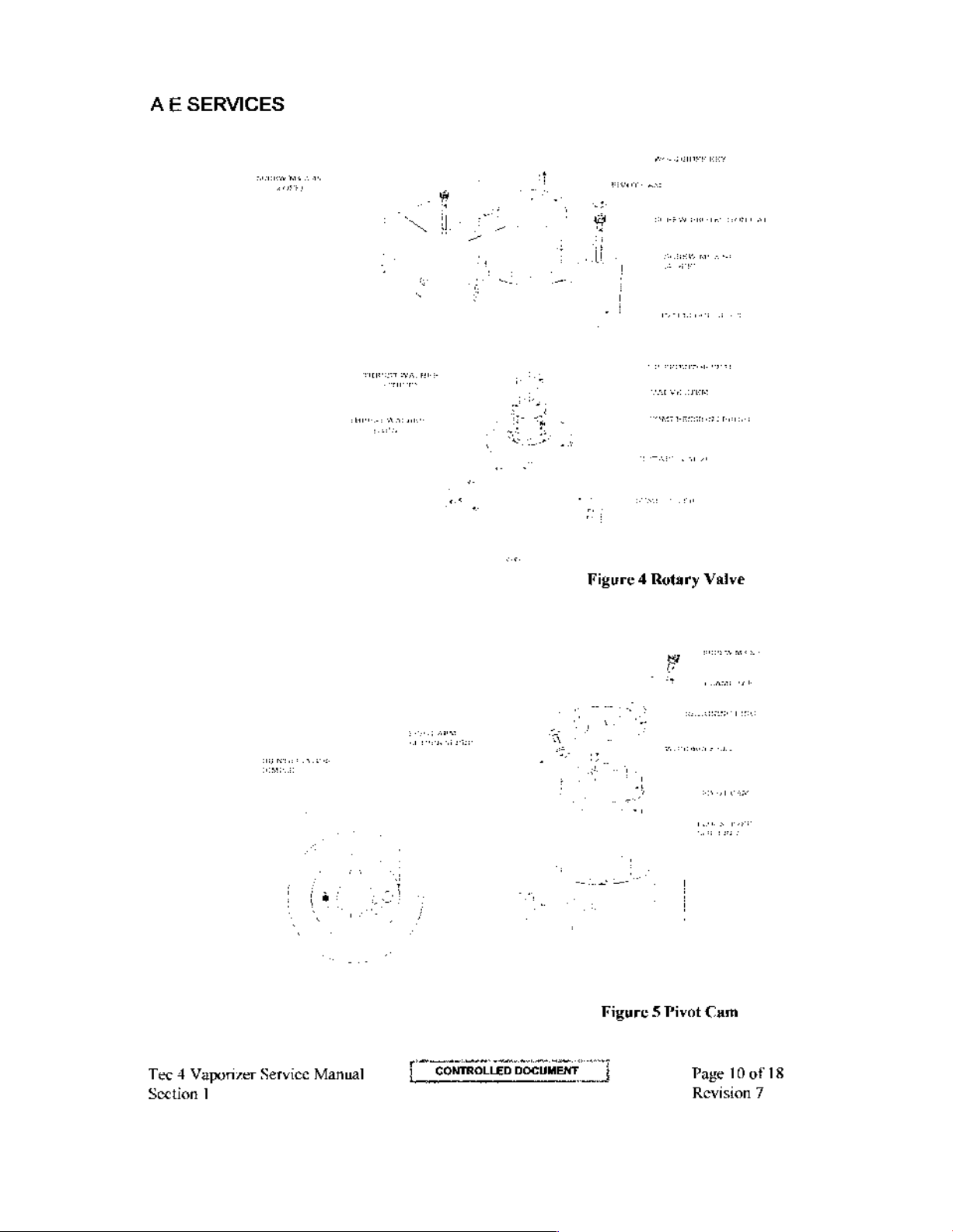
Figure 4 Rotary
Vaive
i
Tec 4 Vaporizer
Section
1
Service
fa
Manual
[CONTROLLED
DOCUMENT
ーーー
Figure 5 Pivot
|
|
|
Cam
Page
10
of
Revision
18
7
Page 20

Page 21
AE
SERVICES
27
28
2.8.1
SUMP
NOTE.
commencement
a)
b)
©)
ASSEMBLY
The
vaporizer
Remove
which
the
Remove
Invort
Cover
one
Cutand
the
retain
killer
Ball
the Filler
the
vaporizer.
Base
side
for
remove
of
this
self-adhesive
the
is
and
Heat
subsequent
Tape.
d)
Unscrew
Lift
Renew
SUMP
off
the
the
AND
and
remove
Sump
Outer
WICKS
Disassembly
a)
Remove
the
self-adhesive
(Figure
shall
6,
Page
have been
operation.
Keyed
filler.
Tfa
keyed
not
misplaced
Assembly
Remove
Pad
and
{he
then
lift
use.
the
Tess tape
the
Assembly
Wick,
(Figure
to
four
Sump
with
securing
6,
Page
label
13)
drained,
I'iller
label
filler
is
fitted,
place
to
one
four
MS
off
the
Outer
release
the
Studs
O-Ring.
with
from
Lift
cotton
13
and
the
Filler.
dried-out
and
and
unscrew
cure
must
side.
Pozi
screws
Support
and
Washers.
off
and
Cover.
Place
Plate.
the
Outor
twine,
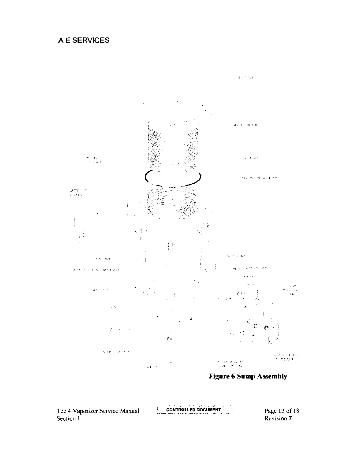
Figure
7,
Page
Max.
tested
the
two
M3
be
taken
to
remove
Discard
Wick
the
all
components
the
Assembly.
14)
prior
to
the
scrows
ensure
that
Outer
to
old
Tesa
b)
Unscrew
Assembly
Note:
On
and
the
©)
Slacken
Heat
Pad
d)
Unscrew
Base
and
e)
Slide
off
©
Remove
adhesive
‘waisted’
2)
Remove
i)
The
is
attached
ii)
Unscrew
The
Non-Spill
the
two
to
the
the
Keyed
Sump,
the
three
up
to
and
remove
When
the
remove
the
Outer
the
Support
tape.
Check
type.
If
and
dispose
Outer
Wick
with
thread
the
two
Cup
M4 x 35
Sump,
Socket
remove
Filler,
a 4 mm
removing
M4
x 6
Texagon
Sump
Base.
the
four
(he
Base
and
Cover,
Plate
(if
that the
nol,
dispose
of
the
is
attached
to
the
M3 x 5
Wick
is
Cap
Screws
the
Filler
Nylon
the Filler
Body,
Socket
MS x 16
the
fitted)
two
of
Pozi
Tleat
which
Sump
them
and
Pad.
Studs
Wicks.
with
thread
Inner
Wick
Support Asscmbly.
Pozidrive
attached
Screws
with
thread
which
Body
and
Ball
is
located
take
Set
Screws
Pan
Head
is
secured
at
the rear of
fit
the
latest
to
the
Spiral
and
secure
the
the Filler
two
PTFE
between
care
not
to
which
are
Screws
to
the
Sump
the
type
during
Support.
remove
the
Body
seals,
the
Filler
Body
lose
the
Ball
used
to
lift
the
in
the
Outlet
Studs
unit
are of the
Cover
by
re-assembly.
The
inner
Wick
Non-Spill
Cup.
Tec 4 Vaporizer
Section
1
Service
Manual
Page
11
of
Revision
7
18
Page 22

Page 23
AE
SERVICES
h)
Remove
Support
surfaces
i)
Note:
‘This
been
serviced
the
four
M4 x 10
Assembly
with
next
complete
Elecsol
ED
procedure
in
the
past
Cheese
or
only
three
lead
with
Thermostat
similar
needs
years.
Screws
and
Cover
cleaning
to
agent
be
carried
remove
Assembly.
out
the
Inner
Clean
if
the
vaporizer
Wick
the
external
has
not
2.8.2
i)
ii)
iii)
iv)
у)
」)
Kit
three
Assembly.
Assembly
a)
Fit
the
Inner
aut
holes
b)
Lay
the
Non-Spili
«)
Fit
the
Outer
d)
Fil
the
Outer
Inspectthe
Clean
210
kPa
Check
Fita
Refît
Washers,
new
are
Non-Spill
Cup
Thermostat
the
‘Thermostat
(30
psi)
maximum.
the
Thermostal
new O-Ring
{he
Thermostat
Fnsure
O-Rings
Wick
aligned
Cup
into
Wick
Wick
to
that the
to
the
onto
the
with
the
Wick
the
Ballle
onto
the
Support
for
signs
of
by
blowing
restriction
the
Sump
and
secure
screws
Inner
Inner
Wick
holes
across
and
secure
Wick
Support
over
the
through
as
Cover
with
are
Wick
Support
Support
in
the rivets.
the
Cup
with
Inner
wick
corrosion
detailed
face.
two
fully
and
damage.
with
clean
in
Section
MS x 16
tightened.
Assembly,
Assembly,
and
two
and
secure
Secure
secure
with
with
M3 x 5
with
Assembly.
compressed
XX.
Screws
then
refit
ensuring
cotton
cotton
Pozi-Drive
cotton
thread.
air
and
spring
the
that
the
thread.
thread,
Screws.
at
cut-
Fit
the
Note:
This
example
the
the
withdrawing
must
be
leaving
283
284
Tec 4 Vaporizer
Section
Sump
Clean
Final
Fita
Fit a new
the
across
1
Cleaning
the
Locking
O-Ring
Sump
the
Service
may
be
Mylar,
Spiral
taken
paper
inside
around
Wick
the
sleeve. A paper
to
sandwiched
of
the
washer
to
the
Cover
using
O-Ring
located
Manual
made
casier
the
Inner
Assembly
ensure
that the
between
Sump
using
to
cach
Hexagon
Sump
Assembly.
the
four
Hexagonal
between
by
first
wrapping a thin
Wick Assembly
over
the
siceve
sleeve
paper does
the
Wick
Llecsol
Stud
Attach
Studs,
the
Sump
onto
may
be
not tear
and
FD
or a similar
as
illustrated
and
ensuring
Cover
film
of
plastic,
to
form a sleeve,
the
Support
used instead
when
the
Spiral.
a
(sce
secure
the
that
and
the
Sump.
and
of
plastic
the
paper
cleaning
Figure
Sump
no
strands
for
then
sliding
then
but
care
is
withdrawn
agent
XX).
Assembly
of
Page
Revision
to
wick
12
of
7
lie
18
Page 24

Page 25
AE
SERVICES
‘Tec 4 Vaporizer
Section
|
Service
Manual
i
R
al
Page
13
of
18
Revision
7
Page 26

Page 27
AE
SERVICES
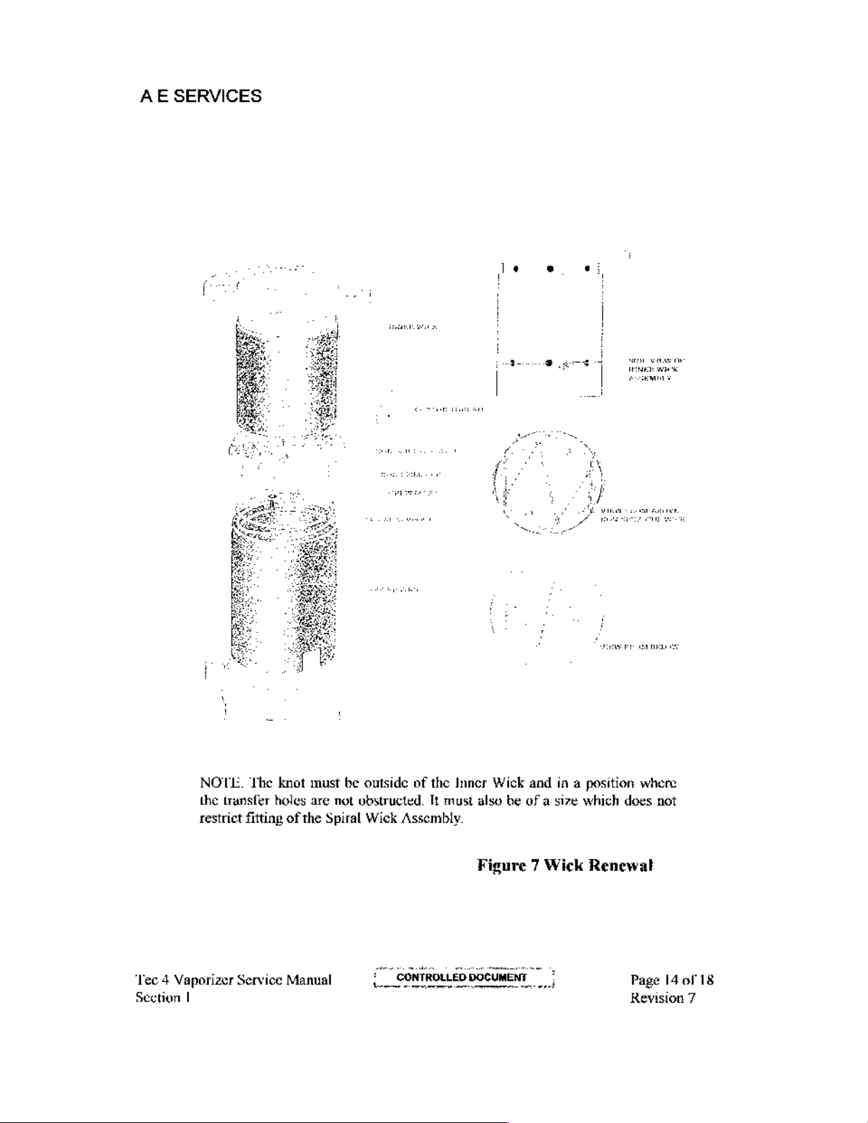
NOLL.
the
restrict
The
knot
transfer
holes
fitting
of
must
are
the
Spiral
be
outside
not
obstructed,
Wick
of the
Assembly.
Inner
Tt
must
Wick
and
in a position
also
be
of a size
Figure 7 Wick
which
Renewat
where
does
not
‘Tec 4 Vaporizer
Section
I
Service
Manual
μα
DOCUMENT
Page
14
of
18
Revision
7
Page 28

Page 29
AE
SERVICES
29
THERMOSTAT
N.B. This
need
Unscrew
and
subsequent
procedure
of
adjustment
the
four
lift
off
the
assembly
use.
during
M4
Obtain a replacement
new
test
and
Secure
head
correctly
Invert
dì
Wrap
Wick
become
Note
Fit
e)
is
in
Secure
to
the
thermostat
sheet.
washers.
the
screws,
the
greaseproof
Support
tom
that
the
Sump
place.
the
sides
on the
Secure
the
Inner
Wick
ensuring
orientated.
vaporizer.
paper
into
position
and
that the
the leg
of
the
Assembly
Secure
Support
of
the
the
Sump.
Plate
needs
only
to
be
performed
calibration.
slotted
Thermostat
thermostat
that
Sump
head
screws
together
with
of
test
sheet.
Staple
to
the
Assembly
round
Inner
Spiral
over
in
to
the
the
three
O-Rings
the
Inncr
over
the
Inner
Wick
is
positioned
the
Wick
to
the
Sump
position
on
the
is
if
the
which
the
correct
the
Sump
Sump
Wick
Wick,
not
Assembly
Cover
the
secure
three
O-Rings,
type
thermostat
Cover
using
Cover
are
in
place
Assembly
ensuring
crumpled
at
the
bottom
ensuring
with
Sump
Studs
thermostat
the
Place
and
record
test
record
the
using
the
and
and
that the
into
the
of
the
that the
the
four
with
is
Inner
Wick
to
one
the
to
two
M5
[Dur
that the
slide the
paper
spiral.
Sump
Sump
Sump
Tesa
Tape
found
to
be
Assembly
side
for
number
the
M4
of
vaporizer
Pozi
screws
slotted
Wick
is
Spiral
has not
O-Ring
Studs
adhering
in
the
Fit
the
8)
Position
Base
M5
Secure
Cover
Tec 4 Vaporizer
Section
1
Service
Outer
the
into
position
Pozi
Pan
the
leat
Base
Manual
Cover
over
Heat
Pad
on
Head
screws.
Pad
to
the
Sump
on
the
base
the
Outer
Cover
the
Sump
CONTROLLED
Studs.
of the
Sump
and secure
with
the
three
DOCUMENT
Assembly.
to
M4
Fit
the
Sump
Grub
screws
the
Studs
Outer
Cover
with
the
in
the
Outer
Page
15
Revision
four
of
18
7
Page 30

Page 31

AE
SERVICES
2.10
2.10.1
FELLER
a)
b)
ASSEMBLIES
Keyed
inspect
black band,
two
When
marked
both
이
Filanew
over
d)
Unscrew
Cam.
open
<)
©
Remove
Spool
Remove
clean,
any foreign
Filler
Assembly
the
Level
Tube.
remove
triangles.
filting
the
new
bands
and
triangles
are
in
the
bottom
O-Ring
the
thread
and
‘This
the
Valve.
the
Valve
and
dry,
te
and
remove
aperation
Spool
Valve
using
a 2
dispose
compressed
matter.
(Figure
it
and
Level
If
il
is
fit
Tube,
8,
the
are
half
of
the
the
Level
then
to
compress
the
three
is
casier
if
from
mm
tommy-bar
of
the
Filler
air
to
the
Page
17)
an
earlier
type,
later
type
fit
two
towards
the
opening
‘Tube
Plug.
it
into
M2.5
x 6
the
Knob
the
Killer
Body.
to
Valve
Seal,
ports
at
which
which
now
in
It
Screws
is
unscrew
the
has
Scals
front
face
the
Block
is
necessary
the
groove.
which
tumed
fully
Fil
three
the
as
illustrated.
rear
of
the
incorporates a single
two black
and
ensure
of
the
to
secure
counter-clockwise
new
Piston
Filler
bands
and
that the
filler
and
that
stretch
the
O-Ring
the
Spool
seals
on
the
End,
Apply a jet
Bady
of
to
remove
black
Valve
lo
8
2.10.2
a)
b) | When
e)
d)
€)
fy
Fita
into
the Filler
Screw
Cap
Inspect
black
two
triangles.
marked
both
Fita
over
Unscrcw
Applya
Body
Fita
Body.
new
Valve
Seal
Body
Filler
Assembiy
the
Level
Tube. If
band,
remove
[tting
the
new
bands
and
triangles
arc
in
the
bottom
new O-Ring
the
thread
and
jet
to
remove
new
Seal
to
and
remove
of
clean,
any
Ring
then
as
illustrated
(Figure
it
is
an
earlier
it
and
fit
the
later
Level
Tube,
are
towards
half
of
the
opening
the
Level
Tube
to
compress
the
Filler
Plug and
dry,
compressed
foreign
to
matter.
the
Filler
Plug
CONTROLLED
and
then
carefully
9,
Page
17)
type,
type
which
fit
two
new
the
front
in
Plug.
Il
it
into
the
the
air
to
the
and
fil
DOCUMENT
refit
which
incorporates
has
two
black
Scals
and
ensure
facc
ol the
the
Block
is
necessary
to
groove.
Drain
Valve
Spindle
ports
at
the
the Filler
Plug
the
Spool Valve
a
single
bands
that
the
filler
and
stretch
the
Assembly.
rear
af
the
into the
Filler
and
black
that
O-Ring
Filler
Tec 4 Vaporizer
Section
|
Service
Manual
Page
16
Revision
of
18
7
Page 32

Page 33

AE
SERVICES
Figure 8 Keyed
Filler
Assembly
Tec 4 Vaporizer
Section
|
Service
7
Manual
i
CC
Figure 9 Screw
Cap
Filler
Assembly
Page
17
Revision
of
18
7
Page 34

Page 35

AE
2.11
SERVICES
a)
b)
ο)
d)
Fitihe
the
Support
Sump
Assembly.
Fit
thelleat
MS x 10
with
Screw
up
Fit
On
the
in
to
the
and
secure
the
Keyed
Pozi-Drive
Filler
and
Sump
Plate
and
Pad
and
Screws.
Body.
tighten
Base.
the
Filler
Filler
only,
secure
Cover
Base
Ensure
If
it
docs,
the
three
Ensure
that
Assembly
check
with
adhesive
and
secure
that the
fit
the
M4 x 6
the
Pad
to
the
that
the 4 mm
tape.
to
the
Cover
latest
type
Socket
is
in
Sump
Sel
firm
using
Ball
Fit
the
Outer
Texagon
base
does
with
cut-outs.
Screws
to
contact
is
with
new
scals.
in
position,
Cover
Studs
with
not
interfere
lift
the
Heat
the
over
four
Pad
Base.
Tec 4 Vaporizer
Section
I
Service
Manual
Page
18
Revision
of
18
7
Page 36

Page 37

AE
SERVICES
SECTION
LEAK
REVISION:
DATE:
TEST
14.03.01
AUTHORISATION.
2
2
APO
一
Vec 4 Vaporizer
Seetion
2
Service
Manual
Page 1 of
Revision
3
2
Page 38

Page 39

AE
SERVICES
VAPORIZER
1)
Connect
2)
Tum
Open
3
)
allow
Start
4
‘The
If
5
the
service
fluid,
Upon
6)
appropriate
SHOULD
Vaporizer
the
vaporizer
the
the
the
maximum
pressure
bench,
rectify
completion
CONTAIN
into
on
line
adjustment
pressure
timer
and
allowable
drop
locate
as
necessary
of a satisfactory
Service
VAPORIZER
NO
Leak
Test
and
set
the
valve
reading
after 30
to
stabilize.
seconds
pressure
is
outside
the
Record
the
source
and
repeat
together with
LEAK
LIQUID
circuit
dial
to
pressurize
drop
accepted
of the
leak
AGENT
(Figure
to
3%
Note
the
check
the
in
30
tolerance,
Icak
using a suitable
the
leak
test,
record
the
the circuit
pressure
seconds
test.
date
TEST
FOR
LEAK
1).
to
200
pressure
reading.
drop.
is 4 mm
return
the
brush
the
pressure
and
relevant
TEST
A’
to
220
mm
Hg
and
Lig
vaporizer
and
drop
to
leak
on
the
the
test
signature
7)
Disconnect
Tec 4 Vaporizer
Section
2
Service
the
vaporizer
Manual
from
the
CONTROLLED
t
Circuit.
DOCUMENT
^^
Page 2 of
Revision
3
2
Page 40

Page 41

AE
SERVICES
Air
Supply
Adjusiment
>———O——
Pressure
Gauge
Valve
mm
Vaporizer
Lg
2.5
Litre
OUT
Blank
a
Taper
on
‘Test
Reservoir
off
Outlet
Fitting
with
Tec 4 Vaporizer
Section
2
Service
LEAK
Manual
FIGURE
TEST
1
CIRCUIT
Page 3 of
Revision
3
2
Page 42

Page 43

AE
SERVICES
SECTION
MAX.
REVISION:
DATF:01.05.95
AUTHORISATION:
3
TEST
2
PSE
‘Tec 4 Vaporizer
Section
3
Service
Manual
Page 1 of
Revision
2
2
Page 44

Page 45

AE
SERVICES
Connect
Pass a [low
Tum
approximately
‘Measured
If
the
drying
Flowmeter
the
vaporizer
of 5 litres'min.
the
vaporizer
30
percentage
measured
out
cycle - see
F.A
Valve
into the
to
its
seconds
when
percentage
Section
Pressure
Regulator
da
REFERENCE
TEST
test
Air
through
maximum
or
more
establishing
is
more
1.
ab
CELL.
CELL
T
„I
SECTION
ST
PROCEDURE
circuit
as
shown
the
circuit.
percentage
note
than
mark.
refractometer
dryness
0.01%
should
the
AR
г
3
in
Figure
Maintain
reading
vaporizer must
1
not
exceed
fringes
F.A,
56-500
Flowmeter
500
lined
up
0.01%
be
anaesthetic
subjected
Valv
cc'm
set
+/-
50
ccim
and
after
agent
to a further
品
Exhaust
to
Room
Vaporizer
Tee 4 Vaporizer
Section
3
Service
[RL
Manual
Mixer
Dodi
0
TEST
ARRANGEMENT
FIGURE
I
Page 2 of
Revision
2
2
Page 46

Page 47

AE
SERVICES
SECTION
CALIBRATION
REVISION:-3
DATE:
AUTHORISATION:-
28,02,2001
4
TESTS
20096
一
一
一
二
_
Tec 4 Vaporizer
Section
4
Service
Manual
Page | of
Revision
4
3
Page 48

Page 49

AE
SERVICES
NOTE
‘The
Computer
Please
Portable
These
Setting
:TTING
Up
which
UP
refer
Refractometers.
CALIBRATION
procedures
and
has
PROCEDURE
to
the
Operating
are
use
of
the
special
SECTION
applicable
Laser
software
Instructions
to
all
Refractometer
installed.
for R & B Instruments
4
TESTS:
Tec 4 vaporizers.
is
facilitated
through a Laptop
Precision
and
Tee 4 Vaporizer
Section
4
Service
Manual
Page 2 of
Revision
4
3
Page 50

Page 51

AE
SERVICES
VAPORIZ,
NOTE
1
Prior
to
the
the
Testing
2
Place a thermometer
he
tested.
3
Install a vaporizer
4
Carry
the
5
Check
section
6 If
a
on
out the
Portable
the
or
the
vaporizer
self
adhesive
the
trolley
These
start
Department
test
Refractometer
test
results
in
the
appropriate
has
label
for
drying-out
procedures
of
testing,
fill
for a minimum
on
the
upper
on
the
test rig,
routine
us
and
against
passed
stuck
all
to
TE
И
are
applicable
the
vaporizer(s)
of 1 hour.
part
of
making
detailed
the
Wall
the
the
in
Section
print 2 copy
talerances
Chart
i.e.
calibration
top
face
of
y
PRO:
to
to
the
one
of
the
sure
that
2.3 of
of
the
results/test certificate,
given
for
AEOW-003
tests,
mark a ‘T°,
the
Interlock
E
all
ee 4 Vaporizers.
'Full’
mark
and
leave
vaporizers
it
is
properly
the
the
(See
Block and
in
the
batch
locked
Operating
relevant
Section
Instructions
vaporizer
10).
in
black
place
to
stand
which
in
place,
is
for
in
this
felt-tip
pen,
the
vaporizer
in
to
on
‘Tee 4 Vaporizer
Section
4
Service
Manual
CONTROLLED
DOCUMENT
Page 3 of
Revision
4
3
Page 52

Page 53

AE
SERVICES
ISOFLURANE
5% 5%
o 0 9
0.5
10 10
20 20
30 30
40 40
50
TINGS
HALOTHANE
05 92
50 20
FOR
TESTI
TEC 4 VAPORIZI
ENFLURANE
5% 7%
04
0.6
10
15
30
40 70
ENFLURANE
OFF
0.5
10
20
30
40
50
6.0
Tee 4 Vaporizer
Section
4
Service
Manual
Page 4 af
Revision
4
3
Page 54

Page 55

AE
SERVICES
SECTION
CURRENT
DATE;
AUTHORISATIO!
DIAL
REVISION:
14,03,01
5
STRIPS
0
Tee 4 Vaporizer
Section
5
Service
Manual
Page 1 of
Revision
2
0
Page 56

Page 57

AE
SERVICES
A
list
is
given
of
current
as
follow:
Dial
together
Strips
with
their
variation
for
each
specific
Vaporizer
Halothane
Isotivrane
Enflurane
Max
%
5
5
8
Dial
Strip
Part
No.
2400-0022/TA
2400-0022/A
2400-0022/A2
2400-0022/18
2400-0022/B
2400-0022/B2
2400-0022/TC
2400-0022/C
2400-0022/C2
2400-0022/D
2406-0022/D2
2400-0022/TB
2400-0022/B
2400-0022/B2
2400-0022/TC
2400-0022/C
2400-0022/C2
2400-0022/D
2400-0022/D2
2400-00227Y7A
2400-0022/Y6A
2400-0022/Y5A
2400-0022/Y4A
Calibration
Marked
Variation
Iighest Yes
Yes
Yes
Yes
Yes
Yes
Yes
Yes
Yes
Yes
Lowest
Highest
Yes
Yes
Yes
Yes
Yes
Yes
Yes
Yes
Lowest
Jighest
Yes
Yes
Yes
Yes
Lowest
Yes
Enflurane
Tec 4 Vaporizer
Scetion
5
Service
7
Manual
2400-0022/57
2400-0022/17R
2400-0022/J6
2400-0022/16B
2400-0022/J5
2400-0022/15B
2400-0022/44
2400-0022/14C
2400-0022/J3C
Highest
Lowest
Yes
Yes
Yes
Yes
Yes
Yes
Yes
Yes
Yes
Page 2 of
2
Page 58

Page 59

A E SERVICES
TEST
AUTHORISATIO!
TOLERANCES
REVISION:
DATE:
0
14.03.2001
„JE
Tee 4 Vaporizer
Section
6
Service
Manual
Page
Lofs
Revision
0
Page 60

Page 61

AE
SERVICES
Tec 4 Enfluratec
Room
Temperature
Table
gives % viv
Enfluranc
ated
Temperature
7%
Tolerances
in
air
Tolerances
(22°C)
(35°C)
Tec 4 Vaporizer
Section
6
Service
Manual
Table
Enflurane
Dial
0.50
1.00
2.00
3.00
4.00
5.00
6.00
7.00
gives % v/v
in
air
Max
0.58
1.10
2.20
3.30
4.40
5.50
6.60
7.70
Page 2 af
Revision
5
0
Page 62

Page 63

AE
SERVICES
Tec 4 Enfluratec
Room
Temperature
Table
Enflurane
Tolerances
gives
Ve
viv
in
air
Min
0.08
Max
0.05
030
0.50
0.70
110
1.70
220
3.30
5.50
5%
(220C)
Tec 3 Vaporizer
Section
6
Service
Elevated
‘Temperature
Dial
0,00
0.20
0.
1
1
24
34
44
5.
Manual
Tolerances
Table
gives % viv
Enflurane
in
2
€323
in
Min
0,00
8.18
0.36
0.54
0.90
135
1.80
2.70
3.60
4.50
air
Max
002
0.22
0.44
0.66
9.10
1.65
2.20
3.30
4.40
5.50
(35°C)
Page 3 of
Revision
5
0
Page 64

Page 65

AE
SERVICES
Tec 4 Isotec
Room
‘Temperature
Table
Diat
0.00
0.50
1.00
2.00
3.00
4.00
5.00
Elevated
Temperature
5%
Tolerances
gives % yy
Isoflurane
in
Min
0.00
0.35
0.85
1.80
2.70
3.60
4.50
air
Max
0.05
0.60
1.10
2.20
3.30
4.40
5.50
Toleranees
(22°C)
(359C)
Tec 4 Vaporizer
Section
6
Service
Manual
Table
gives
Isoflurane
Dial
000
0.50
1.08
2.00
Min
0.00
0.45
0.90
1.80
300 270
400 360
500 450
%
in
air
fe
Max
0.05
0.55
110
2.20
330
4.40
5.50
Page 4 of
Revision
5
0
Page 66

Page 67

AE
SERVICES
‘Room
Temperature
Tolerances
Table
gives
Fluothane
in
(22°C)
Dial
peeves
*(Fluotec
Elevated
4%
TemperatureTolerances
Table
Fluothane
Di
0.50
1.00
2.00
3.00
4.00
5.00
Min
0.35
0.85
1.80
270
3.60
888858
4.50
maximum
gives % viv
Min
0.45
0.90
1.80
2.70
3.60
4.50
in
air
dial
setting)
(35°C)
Max
0.55
AU
226
330
440
5.50
Tee 4 Vaporizer
Scetion
6
Service
Manual
Page 5 of
Revision
5
0
Page 68

Page 69

AE
SERVICES
SECTION
FINAL
INSPECTION
REVISION:
DATE:
20.07.95
AUTHORISATION:
7
2
Tec 4 Vaporizer
Section
7
Service
Manual
Page 1 of
Revision
2
Z
Page 70

Page 71

AE
SERVICES
1.
Examine
signature
2.
Tactile
a)
Tests-
Operate
place.
b)
Check
Tocked'
©)
Tum
resistance
d)
Tuming
e)
Examine
Where a product
test
sheets
ensuring
is
recorded
the
that
in
the
Lock/Unlock
the
vaporizer
position
Vaporizer
the
dial
fully
and
thal
the
vaporizer
the
Key
Filler
does
attention
course
of
the
of
action,
SECTION
nai
all
QA
Approved
lever
can
clockwise
'stop'
control
on
and
bridge
not
conform
Service/Test
Inspection
tests
have been
(o
check
only
be
and
functions
off
check
to
confirm
box.
turned
visually
at
Supervisor
7
Procedure
completed,
for
free
action
on
when
anti-clockwise
correctly.
that
that
il
is
a),b).c),d)
and
thai
and
that
the
Lock/Unlock
ensuring
both
interlock
correct.
or
e)
this
shall
who
shall
decide
the
an
authoritative
return
spring
Lever
that
there
rads
operate
be
brought
on
the
is
in
is
in
the
is
no
00046
correctly.
to
the
appropriate
3.
Thoroughly
4.
When
the
serial
QA
boxes
5.
Attach
6.
Check
the
correct
7.
Place
Tee 4 Vaporizer
Section
5
clean
cleaning
self
that
is
completed,
number
of
on
the
Test
adhesive
ail
labels
positions.
the
cleaned
and
Service
the
vaporizer.
the
Test
Certificate
labeis
to
are
correct
labeled
Manual
ensure
Sheet,
the
that a Serial
Write
the
and
Test
Record.
vaporizer
i.c
vaporizer
vaporizer
as
in a polythene
Number
date
and/or
required.
type,
agent
Plate
sign
type,
bag
is
fitted
the
Final
and
thal
and
record
Inspection
they
are
and
fitted
in
Page 2 of
Revision
2
2
Page 72

Page 73

A.
E.
SERVICES
SERVICE
MANUAL
TEC 4 VAPORIZERS
The
‘Tee 4 Vaporizer
words
Tec
Service
and
Selectates
Manual
are
registered
trade
marks
of
Datex-Ohmeda
Page 74

Page 75

AE
SERVICES
SECT
1
2
3
4
5
TEC 4 VAPORIZER
DOCUMENT
DESCRIYLION
Standard
Leak
Max.
Calibration
Current
Service
Fest
Test
Tests
Dial
Strips
Procedure
SERVICE
AEOM - 04.1
LIST
REV
7
2
2
3
0
140301
010595
280201
140301
MANUAL
DATE
14.03.01
-
RES
6
7
4
9
10
Tee 4 Servico
‘Lest
Final
Thermostat
‘Appendices
For
Manual
‘Tolerances
Inspection
Future Use
0
2
2
0
-
140301
200795
140301
140301
-
Page 76

Page 77

AE
SERVICES
SECTION
FAT
TTING
REVISION:-
DATE:
AUTHORISATION:
PROCEDURE
14.03.01
8
SERVICING
2
_
Tec 4 Vaporizer
Section
8
Service
Manual
Page 1 of
Revision
10
2
Page 78

Page 79

AE
SERVICES
Thermostat
NOTE: — Thermostats
Vaporizers
1
Clean
off
residual
NOTE:
2
3
Open
flapper
between
Whilst
thermostat
Segregate
Using
F-24.5
flapper
still
ffermostat
gauges
mm.
Servicing
covered
due
to
performance
shellac
Itis
not
necessary
that
may
with
fingers,
and
holding
via
inlet
TOI
and
and
(TO2)
Section
by
this
procedure
failure.
from
thermostat
to
remove
detach
flapper
hole.
as
thermostat
hold
up
thermastat
body
open,
RE-EXAMINE.
types
i.c.
E'
102,
check
E=
28.3mm
8
and
Setting
will
have
adjusting
all
traces
been
of
screws/nuts
to
light
source,
for
dirt
blow
clean
Enfluratec
the
effective
and
or
dust
air,
using
and
length
Procedure
removed
and
minimum
shellac,
are
adjusted.
examine
particles,
air-linc
from
stop
just
loose
arca
gun,
serews.
particles
through
Fluotec/lsotec
as
appropriate
(TO!)
4
Nolothat
being
deformed,
Remove
Detach
screws.
Position
spring,
Set
hinge gap
square
to
‘Tee 4 Vaporizer
Section
8
Service
this
stcp
as
the
two
Pozi
the
spring
hinge
Fit
new
hinge
flapper
secure
assembly.
loosely
using
the
thermostat
Manual
is
only
performed
indicated
HD
to
using
tool
by
instability
screws
from
(lapper
(103)
body
securing
the
flapper
and
onto
thermostat
two
Pozi
and
by fully
if
the
thermostat
on
setting
the
leaf
by
removing
secure,
pan
secure
ensuring
body
and
HD
screws.
flapper
tightening
and
the
spring
hinge
or
very
low
spring
and
the
two
hinge
is
fit
clamp
Icaf
spring
two
Pozi
is
suspected
resistance.
one
clamp
plate.
c/sk
Pozi
HD
square
to
plate
and
flapper.
leaf
assembly
pan
HD
screws
Page 2 of 10
Revision
2
of
Page 80

Page 81

AE
SERVICES
Thermostat
Setting
Procedure
Before
and
Passages,
Using a wad
strip,
backwards
as
Install
place
Place
Protect
Ensure
set
into
installing
thermostat
of
clean
potish
the
and
il
becomes
dirty
thermostats
(in
the
test
racks aside
from
dirt
that
the
any
thermostat.
one
of
the
nozzles
thermostats
body
for
paper
adjusting
forwards
or
worn)
(of
onto
dirt
particles,
inserted
screw
end
(approx,
same
type)
racks).
for
24
hours
to
particles
room
Monilor
with
polythene
temperature
thermostat
of
each
test
to
test
racks,
blowing
between
by
rubbing
15
times.)
onto
racks
allow
temperature
shocts
is
stable
at
temperature
rack.
visually
through
tbe
adjusting
(he
(Re-new
ensuring
229C
check
with
paper
wad
paper
'O'
rings
to
stabilize.
+/-
10€
using a thermometer
between
an
air-line
screw
flapper
to
and
Bi-metal
vigorously
wad
frequently
are
correctly
before
attempting
clear
in
to
inserted
Fee 4 Vaporizer
Section
8
Service
Manual
Page 3 of
Revision
10
2
Page 82

Page 83

AE
SERVICES
-M
i
Tec 4 Vaporizer
Section
8
Service
FIGURE
Manual
し
1
Thermostat
1
го
Test
Arrangement
1
Page 4 of
Revision
10
2
Page 84

Page 85

AE
SERVICES
FIGURE
2
Thermostat
AIT
e
Assembly
ΕΟΝ
CETTE
SETTING
DOME
Tee 4 Vaporizer
Section
8
Service
Manual
|
Page 5 of
Revision
2
10
Page 86

Page 87

AE
SERVICES
Minimum
Flow
a)
b
9
d
9)
В
Maximum
Flow
Stop:
Adjust
Ensure
Back-alf
Connect
(minimum
38
and
‘Tighten
Re-adjust
Record
Setting
Check
the
of
the
test
Adjust
5.0
litres/min
Tighten
Record
the
air
flow
to 5 Litres/Min
that
water
manometer
the
adjusting
air
supply
stop)
44
cms
water.
lock-nut
as
necessary
date,
pressure,
temperature
rack.
setting
screw
air
lock
nut.
date,
pressure
screw
to
nozzle
so
that
then
re-check
and
indicated
to
obtain a manometer
in
accordance
and
without a thermostat
indicates
so
that
of
test
the
indicated
pressure
temperature
with
temperature
zero.
it
is
rack
pressure
reading,
on
by
the
thermometer
tolerances,
on
in
clear
of
the
bi-metal
and
adjust
flow/temperature
is
between
AEQF-10.7.
1/4.
inserted
reading
ARQF-10.7,
at a flow
1/4,
circuit,
strip.
in
the
nozzle
of
stop
d)
e
‘Yee 4 Vaporizer
Section
8
Service
The
thermostat
impaired
if
instability.
careful
and
is a relatively
the unit
can
is
be
caused
(horough
bearing surfaces
Maintain
Observe
Using a finger,
screw
not
Record
Similar
serew
Record
If
the
for
air
flow
at
pressure
reading
apply a moderato
for
approx, | sec
altered
rectification,
from
its
date,
pressure,
to
(c)
but
instead,
and
releasing
date,
pressure,
thermostat
Fails
5.0
original
after
Manual.
delicate
roughly
cleaning
handled.
by
dirt
and,
Litres/Min
on
Manemcter.
then
release
setting
and
temperature
open
instrument
Alternatively,
or
dust.
if
necessary,
to
the
force
against
finger.
by
more
on
flapper
by
approx. | second.
and
temperature
the
'pustvpull
on
tests
and
the
stability
thermostat
Stability
thermostat.
ALOI-10.1.1/7.
pulling
is
usually
re-polishing
the
head
of the
Check
that the
than
approx.
at
pressure
1.0
head
of
restored
of
the
setting
cm
adjusting
AEQF-10.7.1/4
reject
thermostat
and
Page 6 of 10
Revision
may
be
by
has
water.
sogrogato
2
Page 88

Page 89

AE
SERVICES
A
final
check
on
the
thermostat
installation
in
the
vaporizer.
setting
As
follows:
shal!
be
carried
out
prior
to
1
2)
3)
41
3)
6)
Ensure
Set
Pass $ litres/min
Check
Record
Apply
temperature
manometer
to
through
pressure
date,
shellac
reading
pressure,
to
low
is
within
zero,
and
temperature
permitted
Airflow
at 5 litres/min.
tolerance,
thermostat.
to
tolerance
temperature
chart.
on
stop
and
AEQF-10.7.1/4,
setting
screws.
Tec 4 Vaporizer
Section
8
Service
77
como
Manual
Eb
Page 7 of 10
Revision
2
Page 90

Page 91

AE
SERVICES
Fee 4 Vaporizer
Enfluratec
Enlluratce
Enfluratec
Enfluratec
Fluotec
Fluotec
Fluotec
Fluotec
Isotec
Isoice
5%
4%
5%
5%
5%-
5%
-
5%
7%
5%
7%
-
-
-
-
-
-
-
-
Screw
Serew
Keyed
Keyed
Screw
Screw
Serew
Keyed
Screw
Keyed
‘Thermostat
Type
Ethrane
Fthrane
Lthranc
Ethrane
Fluotoe
Fluotee
Fluoteg
Fluotec
Huotec
Fluotec
Tec 4 Vaporizer
Section
8
Service
PEG
Manual
ecu
I
Page 8 of 10
Revision
2
Page 92

Page 93

AE
SERVICES
TOLERANCES
Temperature | Temperature | Nominal
°C
o
189
192
o
FOR
°F
660
66.5
670
“e
5
68.0
i
68.5
69.0
i
69.
5
m0
70.5
710
71.5
72.0
725
730 212
735
74.0
TAS
750
755
76.0
HALOTHANE
gm
30,3
29.3
|
283.
275 29.3
26.
26.0
254
24.8
|
7
we
23.6 24.8
23.0
-
225
221
ив
.
20
20.5
>
20.
19.8
19.
191
TO
7
8
т
4
THERMOSTATS
Maximum
em
HO
327
315
303
때
|
ーー
“ao
283
275
26.7
26.0
254
242
23.6
225
21
21.6
2
20.8
205
20.1
198
2
7
`
|
‘Yee 4 Vaporizer
Section
8
Service
Manual
Page 9 of 10
Revision
2
Page 94

Page 95

AE
SERVICES
TOLERANCES
Temperature
|
-
"C
189
193
194
197
209
203
206
ms
sm
214
23.3
239
22
244
|
|
|
|
Er
|
7
|
Temperature | Nominal | Maximum | Minimum
7
|
|
|
FOR
of.
66.0
66.5
670
675 282 302
680
685 265
690
65
700
705
71.0
715
720 218
ns
we
735
740
745
750
755
760
ENFLURANE
_
_
_
THERMOSTA’
em
HO
315
309 327 282
29.1
273
257
243
242 257
236 250 224
23.0
224 236
212
206 218
20.0
195
19.0
185
181
176 185
cm
lbO
338
314 273
292
382
273
26.5
243
23.0
224
212
20.6
20.0
19.5
190
m2
em
1,0
291
26.5
257
25.0
243
236
23.0
218
“312
206
200
195
190
185
“180
176
168
|
|
|
|
Tec 4 Vaporizer
Section
8
Service
Manual
Page
10
of
10
Page 96

Page 97

AE
SERVICES
SECTIO
APPENDICES
REVISION:
DATE-
AUTHORISATION:-_.
15.03.2001
0
Toc 4 Vaporizer
Section
9
Service
Manual
‘CONTROLLED
DOCUMENT}
Page
I
Revision
0
Page 98

 Loading...