

Ohmeda Halogen Phototherapy Light II User manual
t
Halogen
Operation
Phototherapy
and
Maintenance
Light
Manual
Uk>CO
-O^B-XOO
II
i.i-
.1- ;. • i -. •
iW-^de
'ii
i)iii«»
•
v.-
,¥*
L
POL
I boS - 0
HHT-*M3
0 3+--^ ^>"

1.2
SPECIFICATIONS
Size:
Weight:
Voltage: 115
Current:
Fuse: 3 amp, 125 volts, 1-1/4" slo-blow
Lamp type: Halogen, 150
Irradiance: 3 to 76 microwatts/square centimeter/nanometer in the
Lamp intensity: 6,500 foot candles
Lamp
Lamp
Lamp
Lamp
4-1/2 inches high
spot
color
and
arm
housing
Rail/Wall
Floor Stand Model - approximately 37 pounds unpacked
volts
8.5
amp
425-475 nanometer spectrum at bed level, depending on
lamp to patient distance.
size:
temperature:
fully
and
Mount
60 Hz
Variable
size selected and light to mattress distance.
extended-34
yoke
watt,
Model
from
3,150
12
inches
-
approximately
20
Volt,
3 to
degrees
inches
long
type Burton
20
inches
Kelvin
long
by
6-1/2
24
depending
inches
pounds
wide
unpacked
on
aperture
by
Average
Leakage
lamp
life
current:
rating:
With
amperes. * >
With
amperes. *
* Measured at any exposed metal surface on
units.
1,800
1000 and 3000 hours typically)
the
ground
the
ground
hours
wire
wire
(lamp
open
closed
life
.less
less
will
than
than
vary
100
5
between
micro
micro
115
volt
page 3
2/
SETUP
..or
AND
CHECK
OUT
PROCEDURE
The Phototherapy Light
service personnel.
Follow the instructions carefully to ensure proper mounting
and
safe
operation.
should
Because
only be installed by qualified
of the variety of possible
mounting configurations you may have to order specialized
hardware. Hardware requirements for some applications are
as
follows:
1.
Rail
Warmer System order a rail mounting kit (Stock no.
6600-0051-800)
2.
Wall Mounting - Two
provided. This hardware is satisfactory when properly
installed on a typical
different hardware may be required for other wall
constructions.
2.1
INSTALLATIONONTHE
Mounting
-
For
.
installation
3/8x3
wood
INFANT
inch lag screws are
frame drywall. However,
WARMER
on
the
SYSTEM
Ohmeda
Infant
^
WARNING: These mounting instructions must only be carried
out by qualified service personnel. Be sure to install all
components in the proper order and orientation.
CAUTION: Do not allow the wires to be pinched during
installation.
Verify
Qty. Description
2
that-t*he
Cover
Hole
Arm
Transformer housing assembly with wire harness
Threaded
end
Backplate for transformer housing
Plastic
Friction plug
Spring-
Lamp-head
3/16
Container
Lag
screws
following parts are included:
plates
plug
cap
washer
plug
inch
assembly
hex
key
of
grease
with
wrench
wire
harness
/mi)^
^^
Tools
Required:
3/16 inch hex
key
wrench (included)
9/16 inch nut driver or socket wrench
Medium
Mallet
size
flat
blade
screwdriver
=-
ri
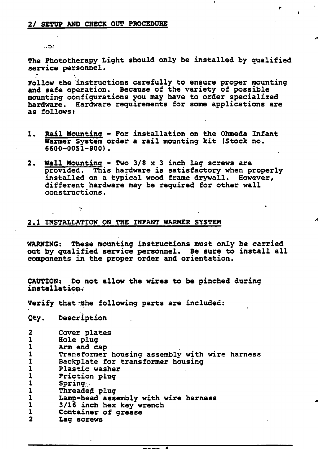
Insert
the
the mounting
backplate
and
bracket
the
transformer
studs
through the
housing
(Fig-ure2).
Secure the transformer housing and backplate- to the
mounting
Tighten
Mounting
Bracket
bracket.
the
nuts.
Use two
nuts
as shown in Figure
holes
in
2.
Slid*
Bracket
NOTE:
have
expanded
Figure
The
been
articulating
removed to show the bracket assembly in
detail. -
2.
Bracket Mounting Assembly
arm
and
the
lamp-head
Power
Cord
Nuts
assembly
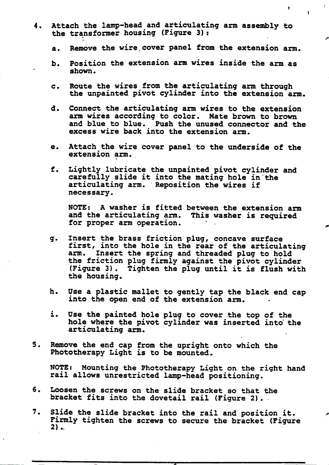
4.
Attach
the
lamp-head
and
the transformer housing (Figure
a.
b.
Remove
Position
shown•
the
wire
the
cover
extension
articulating
3):
panel
arm
from
wires
arm
the
inside
extension
assembly
the
arm
to
arm.
as
c.
Route
the
wires
from
the articulating arm through
the unpainted pivot cylinder into the extension
arm.
d. Connect the articulating arm wires to the extension
arm wires according to color. Mate brown to brown
and
excess
e.
Attach the wire
extension
f.
Lightly lubricate the unpainted pivot cylinder and
blue
to
wire
blue.
back
arm.
Push
into
cover
the
the
panel
unused
extension
connector
arm.
and
to the underside of the
the
carefully slide it into the mating hole in the
g.
articulating
necessary.
NOTE: A
and
the
for proper arm operation.
Insert the brass friction plug, concave surface
first,
arm. Insert the spring and threaded plug to hold
the
friction
(Figure
the housing.
washer
articulating
into
3)
arm.
the
plug
Reposition the wires if
is
hole
firmly
fitted
arm.
in the
between
This
rear
the
washer
of the articulating
against the pivot cylinder
extension
is
required
arm
. Tighten the plug until it is flush with
h.
Use a
plastic
mallet
to
gently
tap the
black
into the open end of the extension arm.
i.
Use the
hole where the pivot cylinder was inserted
articulating
5.
Remove the end cap from the upright onto which the
Phototherapy Light is to be mounted.
NOTE: Mounting the Phototherapy Light on the right hand
6.
rail
Loosen
allows
the
bracket
7.
Slide
Firmly
2)..
the
tighten
painted
unrestricted
screws
fits
into
slide
the
hole
arm.
on
the
the
dovetail
bracket
screws
plug
to
lamp-head
slide
bracket
rail
into
to
the
secure
cover
the top of the
positioning.
so
(Figure
rail
and
the bracket
into"
that
the
2).
position
end cap
the
it.
(Figure
^%
8.
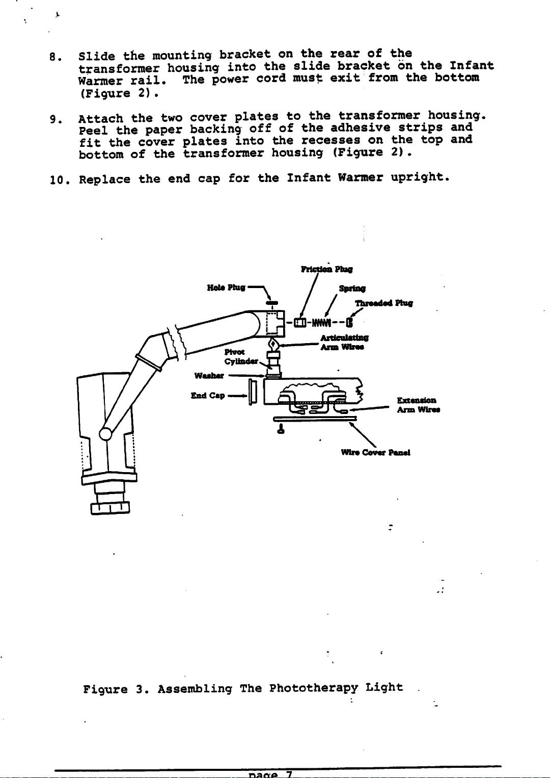
Slide the mounting bracket on the rear of the
transformer housing
rail.
2)
.
the two
the
paper
the
cover
of the transformer housing (Figure 2).
the
9.
10.
Warmer
(Figure
Attach
Peel
fit
bottom
Replace
The
cover
backing
plates
end
power
cap
into
the
slide
bracket on the Infant
cord must exit from the bottom
plates
off
into
for
the
the
to
the
of
the
recesses
Infant
transformer
adhesive
Warmer
housing.
strips
and
on the top and
upright.
Hot*
Plug
Friction
,_
LJJ
Phig
Inrnl
Articulating
Arm
Spring
u
Wires
Wire
Threaded
Cover
Plug
Extension
Arm
Panel
Wires
Figure
3.
Assembling
The
Phototherapy
Light
11.
Check
the
degrees,
degrees.
and will
12.
Adjust
required.
a.
the
movement
articulating
and
horizontally
Verify
remain
the
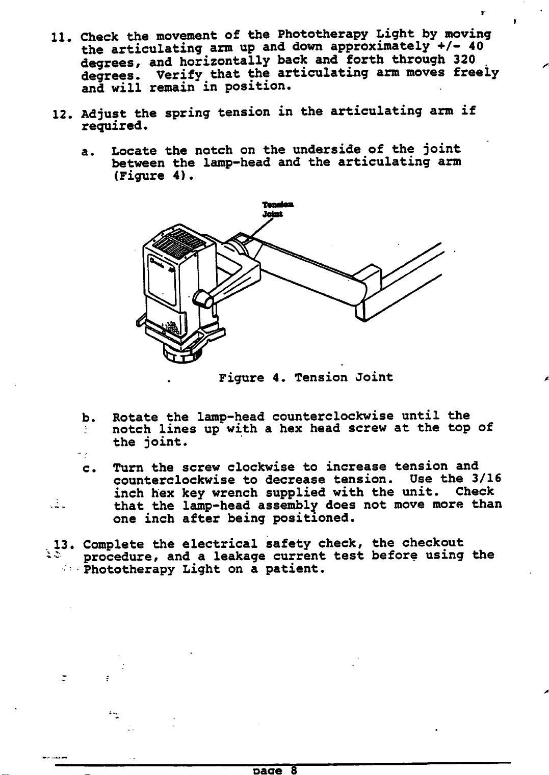
Locate the notch on the underside of the joint
between the lamp-head and the articulating arm
(Figure 4).
spring
of
arm
up
that
in
position.
tension
the
Phototherapy
and
down
back
the
articulating
in
and
the
Light
by
approximately
forth
through
arm
moves
articulating
moving
+/-
320
freely
arm
40
.
if
•--
13.
*:
Figure
b.
Rotate
notch
the joint.
c. Turn the screw clockwise to increase tension and
counterclockwise
inch
that the lamp-head assembly does not move more than
one inch after being positioned.
Complete the electrical safety
procedure,
Phototherapy Light on a patient.
the
lines
hex key
lamp-head
and
a
up with a hex head screw at the top of
wrench
leakage
4.
Tension Joint
counterclockwise
to
decrease
supplied
check,
current
tension.
with
test
the
the checkout
before
until
Use
unit.
using
the
the
Check
3/16
the
page
8
2.2
WALL
MOUNTING
INSTALLATION
WARNING:
out
by
These
mounting
qualified
componentsinthe
CAUTION:
installation.
Verify
Qty.
2
Do not allow the wires to be pinched during
that
the
Description
Cover
Hole
Arm
Transformer housing assembly with wire harness
plates
cover
end
cap
Backplate
Plastic
Friction plug
Spring
Threaded
washer
Lamp-head assembly with wire harness
3/16
Container of grease
Lag
inch
screws
service
proper
following
for
the
plug
hex
key
instructions
personnel.
order
parts
transformer
wrench
and
orientation.
are
must only be
Be
sure
to
included:
housing
carried
install
all
Tools
1.
2.
3.
4.
Required:
Electric drill
3/16
9/16 inch
Medium
Mallet
Locate a wood stud in the wall near the desired mounting
position.
mounting height.
Use
the
the
mounting
one.
Drill two holes
depth
marked in step
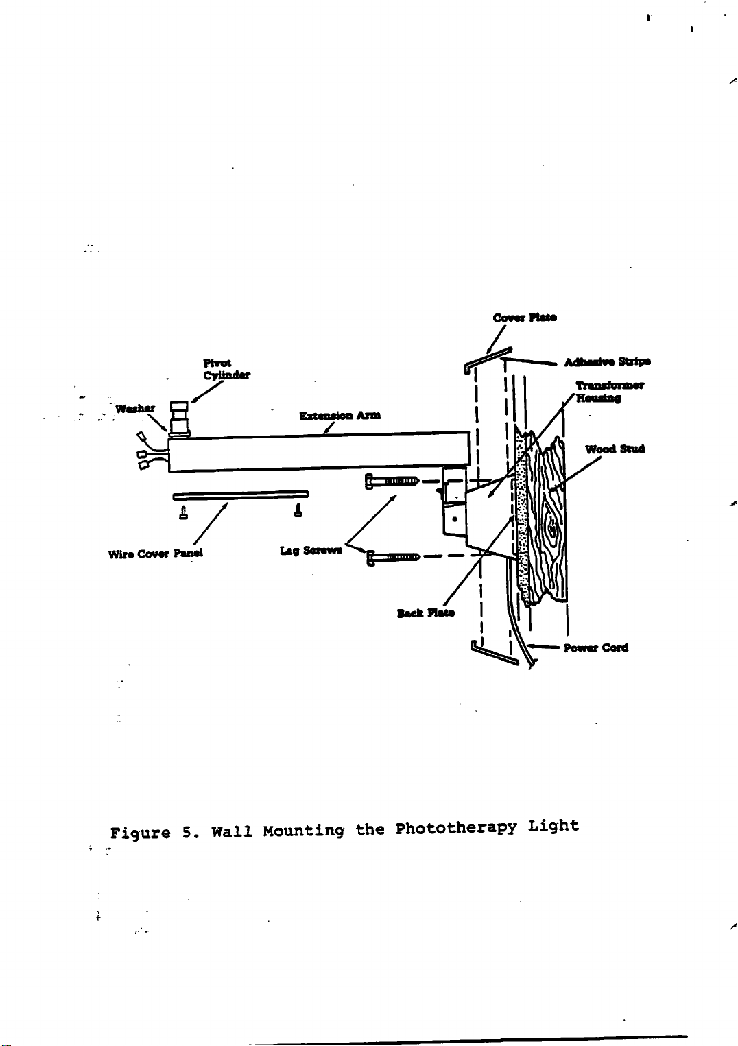
Place the transformer housing on top of the backplate
(approximately
with the
housing.
assembly to the wall (Figure
Draw a
backplate
holes
2.
power
Use
cord
the
inch hex key wrench
nut
size
vertical
as
a
template
on
the
(1/4
inch
1-1/2
exiting
two
lag
with
driver
flat
line
blade
over the
to
vertical
diameter)
inches)
from
screws
the bottom of the
provided
5).
1/4" x 1-1/2" drill bit
(included)
or
socket
screwdriver
stud
mark
line
to the the required
at
the
drawn
the
wrench
at the
location
in
locations
to
secure
of
step
the
NOTE:
This
Phototherapy
requires
Light
and
two
another
page
people,
to tighten the
9
one
to
support
screws.
the
Cover
/*%
Plats
Washer I
Wire
Cover
&
Panel
pivot
Cylinder
Lag
Screws
Adhesive
Transforms?
Housing
Wood
Power
Strips
Stud
Cord
Figure5.Wall
Mounting
the
Phototherapy
Light
/*"%
Lamp-head
Articulating
Arm
f*
IfttT
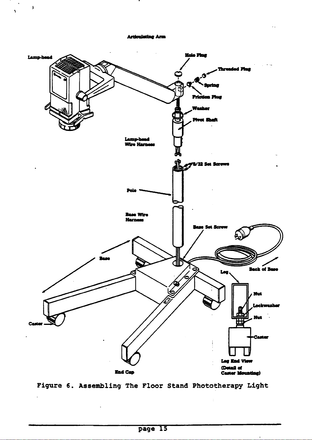
Figure 6.
Bod Cap Caster Mounting)
Assembling
(Detail
The
Floor Stand Phototherapy Light
page
15
of
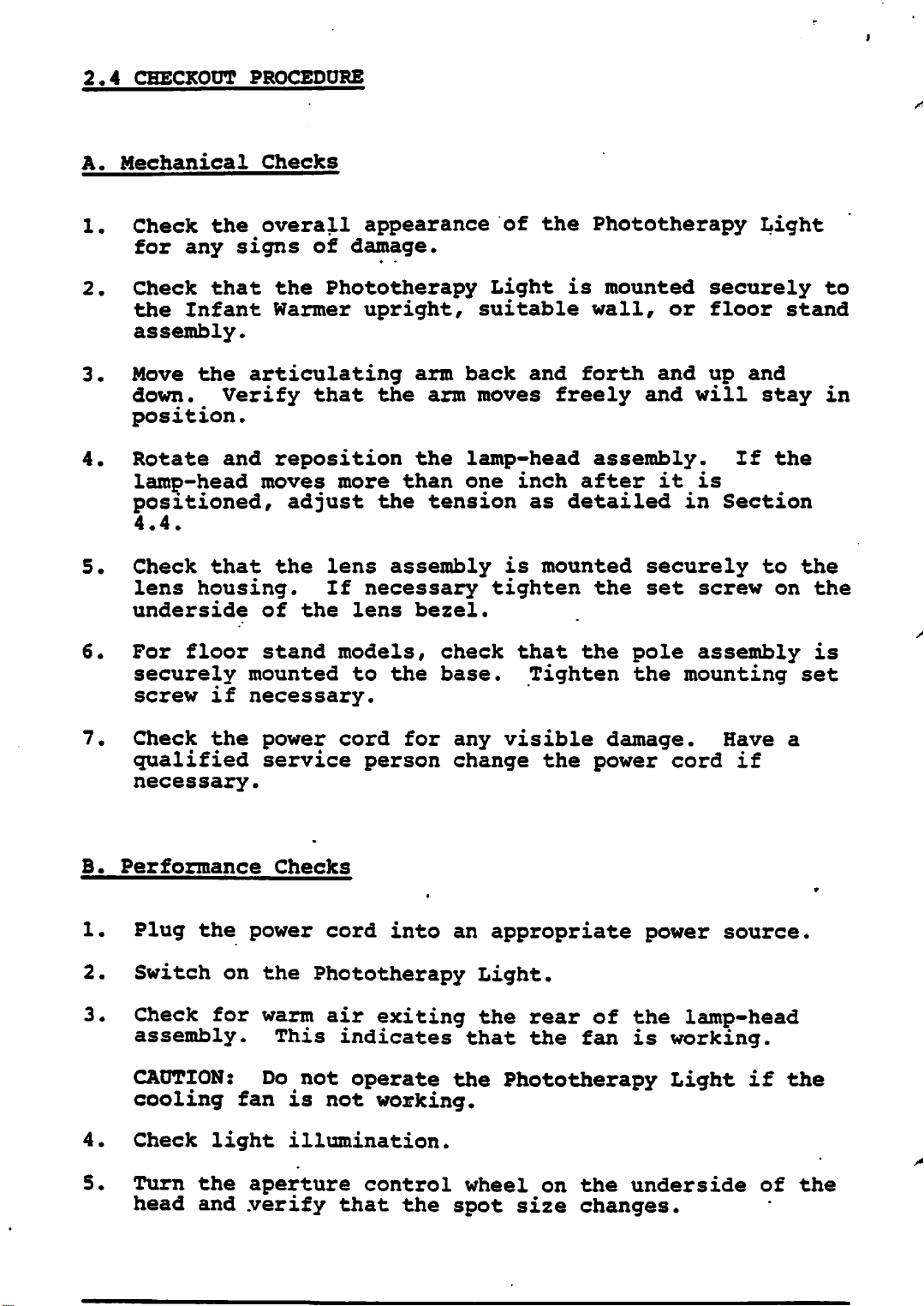
2.4
CHECKOUT
A.
Mechanical
PROCEDURE
Checks
1. Check the overall appearance of the Phototherapy Light
for any signs of damage.
2.
Check that the Phototherapy Light is mounted securely to
the Infant Warmer upright, suitable wall, or floor stand
assembly.
3.
Move the articulating arm back and forth and up and
down. Verify that the arm moves freely and will stay in
position.
4. Rotate and reposition the lamp-head assembly. If the
lamp-head
moves
more
than
one
inch
after
it
is
positioned, adjust the tension as detailed in Section
4.4.
5.
Check that the lens assembly is mounted securely to the
lens housing. If necessary tighten the set screw on the
underside
6.
For floor stand models, check that the pole assembly is
securely mounted to the
of
the
lens
bezel.
base.
Tighten the mounting set
screw if necessary.
•<£^
7. Check the power cord for any visible damage. Have a
qualified service person change the power cord if
necessary.
B.
Performance
1.
Plug the power cord into an appropriate power source.
2.
3.
Switch
on the Phototherapy
Check for warm air exiting the rear of the lamp-head
Checks
Light.
assembly. This indicates that the fan is working.
CAUTION: Do not operate the Phototherapy Light if the
cooling
fan
is not
working.
4. Check light illumination.
5.
Turn
head and
the
aperture control wheel on
.verify
that the spot size changes.
the
underside
of the
If the unit
be
repaired
fails
and
any part of the
tested
before
use
checkout;
on a
patient.
procedure it must
3/
OPERATION
/^S^ffiv
WARNING:
connected.
Do not
An
electrical shock
open
the
lamp-head
assembly
hazard
exists.
with
power
CAUTION: To avoid overheating, do not cover any of the
vents in the lamp-head assembly and do not operate the light
if the cooling fan is not operating. Check for warm air
exiting the rear of the lamp-head assembly during operation.
3.1
CONTROLS
(Figure
A.
On/Off
7)
Switch
On the rail/wall mounting model the On/Off switch is located
on the column at the top of the transformer housing. On the
free standing model the On/Off switch is located at the top
of
the
pole.
B.
Aperture
Control
Wheel
Spot size is a function of the aperture size and the
distance between the bed and the light. To change the
aperture size rotate the aperture wheel located on the
underside of the lamp-head.
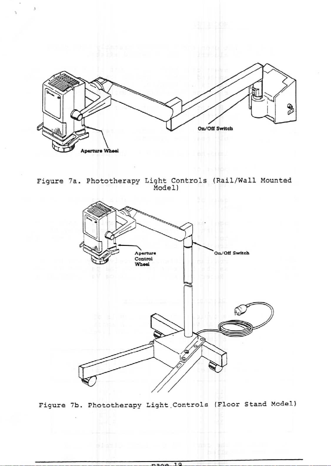
Figure
7a.
Phototherapy Light Controls (Rail/Wall Mounted
Model)
Figure
7b.
Phototherapy Light.Controls
(Floor
Stand
Model)
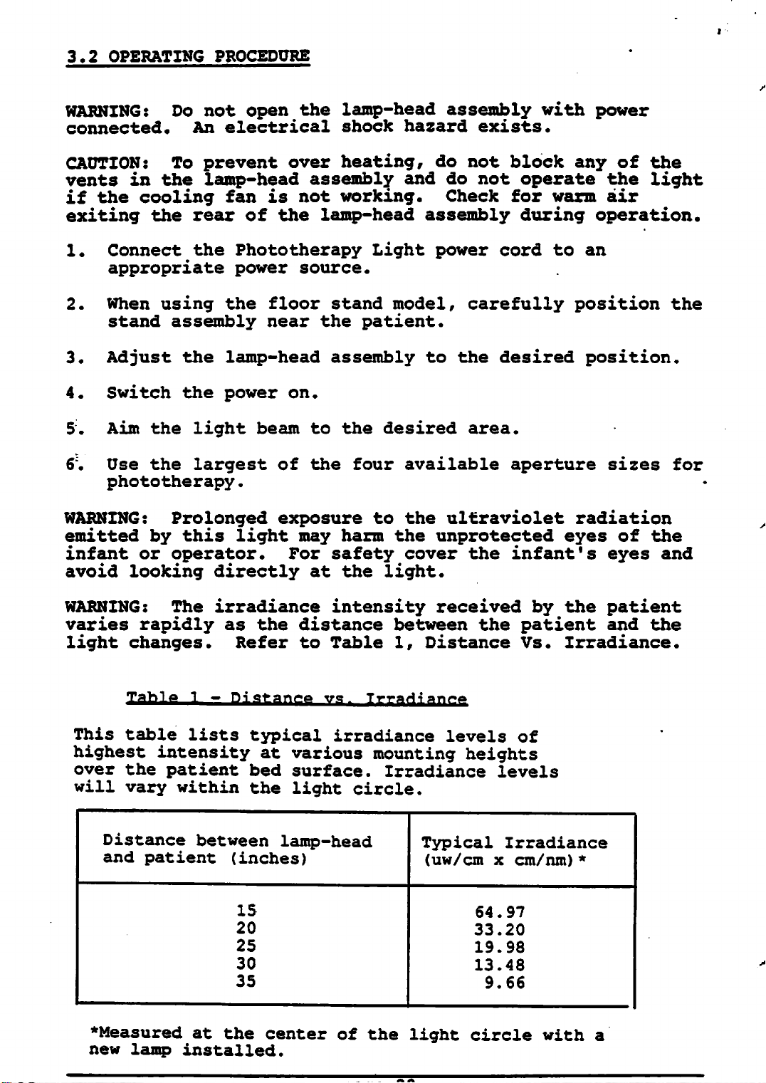
3.2
OPERATING
PROCEDURE
WARNING: Do not open the lamp-head assembly with power
connected.
An
electrical
shock
hazard
exists.
CAUTION:
To prevent over
heating,
do not block any of the
vents in the lamp-head assembly and do not operate the light
if the cooling fan is not working. Check for warm air
exiting the rear of the lamp-head assembly during operation.
1.
Connect the Phototherapy Light power cord to an
appropriate power source.
2.
When using the floor stand model, carefully position the
stand assembly near the patient.
3.
Adjust the lamp-head assembly to the desired position.
4.
Switch the power on.
5.
Aim
6'.
Use the largest of the four available aperture sizes for
the light beam to the desired area.
phototherapy.
WARNING: Prolonged exposure to the ultraviolet radiation
emitted by this light may harm the unprotected eyes of the
infant or operator. For safety cover the infant's eyes and
avoid looking directly at the light.
WARNING: The irradiance intensity received by the patient
varies rapidly as the distance between the patient and the
light changes. Refer to Table 1, Distance Vs. Irradiance.
Table
1 -
Distance
vs.
TrraHianr*
This table lists typical irradiance levels of
highest intensity at
over
the
patient
will vary within the light
Distance between lamp-head
and
patient
(inches)
15
20
25
30
35
bed
various
surface.
circle.
mounting
Irradiance
Typical
(uw/cm
heights
levels
Irradiance
x
cm/nm)*
64.97
33.20
19.98
13.48
9.66
♦Measured
new
lamp
at the center of the light circle with a
installed.
 Loading...