

Page 1
Giraffe
®
OmniBed
Service Manual
®
Page 2

Important
The information contained in this service manual pertains only to those models of products which are marketed by Ohmeda Medical as of the effective date of this manual or the latest revision thereof. This service
manual was prepared for exclusive use by Ohmeda Medical service personnel in light of their training and
experience as well as the availability to them of parts, proper tools and test equipment. Consequently,
Ohmeda Medical provides this service manual to its customers purely as a business convenience and for the
customer’s general information only without warranty of the results with respect to any application of such
information. Furthermore, because of the wide variety of circumstances under which maintenance and repair
activities may be performed and the unique nature of each individual’s own experience, capacity, and qualifications, the fact that a customer has received such information from Ohmeda Medical does not imply in
anyway that Ohmeda Medical deems said individual to be qualified to perform any such maintenance or
repair service. Moreover, it should not be assumed that every acceptable test and safety procedure or
method, precaution, tool, equipment or device is referred to within, or that abnormal or unusual circumstances,
may not warrant or suggest different or additional procedures or requirements.
This manual is subject to periodic review, update and revision. Customers are cautioned to obtain and consult
the latest revision before undertaking any service of the equipment.
CAUTION w Servicing of this product in accordance with this service manual should never be undertaken
in the absence of proper tools, test equipment and the most recent revision to this service
manual which is clearly and thoroughly understood.
This static control precaution symbol appears throughout this manual. When this symbol appears
next to a procedure in this manual, static control precautions MUST be observed. Use the static
control work station (Stock No. 0175-2311-000) to help ensure that static charges are safely
conducted to ground and not through static sensitive devices.
Technical Competence
The procedures described in this service manual should be performed by trained and authorized personnel
only. Maintenance should only be undertaken by competent individuals who have a general knowledge of and
experience with devices of this nature. No repairs should ever be undertaken or attempted by anyone not
having such qualifications. Genuine replacement parts manufactured or sold by Ohmeda must be used for all
repairs. Read completely through each step in every procedure before starting the procedure; any exceptions
may result in a failure to properly and safely complete the attempted procedure.
Definitions
Note: A note provides additional information to clarify a point in the text.
Important: An Important statement is similar to a note, but is used for greater emphasis.
CAUTION: A CAUTION statement is used when the possibility of damage to the equipment exists.
WARNING: A WARNING statement is used when the possibility of injury to the patient or the operator exists.
m
x
y
~
Type B Electrical equipment
Protective ground
Functional Ground
Alternating Current (AC)
Static Control Precaution
European Union Representative
Page 3

Table of Contents
Chapter 1 – Functional Description
1.1 Control Board .............................................................................................1-1
1.2 Relay Board ...............................................................................................1-3
1.3 Display Driver Board/EL Display.................................................................1-4
1.4 LED Board .................................................................................................1-4
1.5 Power Supply .............................................................................................1-4
1.6 Peripheral Components..............................................................................1-4
1.61 Rail and Heater Door Switches ..........................................................1-5
1.7 DataLink Option .........................................................................................1-5
1.8 Servo Controlled Oxygen Option ................................................................ 1-6
Chapter 2- Service Checkout
2.1 Setup..........................................................................................................2-1
2.2 Mechanical checks.....................................................................................2-1
2.3 Controller checks .......................................................................................2-2
2.4 Humidity check...........................................................................................2-3
2.5 Servo Controlled Oxygen check .................................................................2-3
2.6 Accessory checks ......................................................................................2-4
2.5 Cable Connections and Mechanical Controls ............................................. 2-5
Chapter 3- Calibration and Maintenance
3.1 Maintenance schedule ...............................................................................3-1
3.2 Special tools...............................................................................................3-1
3.3 System Calibration .....................................................................................3-3
3.4 Line Volt age Calibration..............................................................................3-3
3.5 Humidifier Calibration .................................................................................3-4
3.6 Servo Controlled Oxygen Calibration .........................................................3-4
3.7 Scale Calibration ........................................................................................3-5
3.8 Leakage Current ........................................................................................3-5
3.9 Ground Resistance ....................................................................................3-5
Chapter 4- Troubleshooting
4.1 Service Screen...........................................................................................4-1
4.2 Alarm Messages ........................................................................................ 4-5
4.3 Error Codes................................................................................................4-8
4.4 Troubleshooting Table ................................................................................4-13
4.5 Additional Troubleshooting Tips..................................................................4-16
4.6 Servo Controlled Oxygen ...........................................................................4-19
Servo Controlled Oxygen Service Screen..................................................4-19
Servo Controlled Oxygen Alarm Messages ...............................................4-20
Servo Controlled Oxygen Troubleshooting Tips .........................................4-22
Chapter 5- Repair Procedures
5.1 Canopy removal for replacement ...............................................................5-1
5.1 1 Replacing the seals............................................................................ 5-2
5.12 Porthole Door Replacement...............................................................5-3
5.2 Canopy Lift Assembly Repair Procedures ..................................................5-4
5.21 Removing the right upright (motor side) ............................................. 5-4
5.22 Removing the left upright ...................................................................5-7
5.23 Right rail internal repairs ....................................................................5-8
5.231 Removing the inner rail assembly..............................................5-8
5.232 Replacing rollers and tension springs ........................................ 5-8
5.233 Replacing the micro-switches....................................................5-9
5.234 Separating the lift rail from the belt channel...............................5-9
5.235 Replacing the drive belt .............................................................5-10
5.236 Replacing the rail buoyancy springs ..........................................5-10
5.24 Re-assembling the right upright .........................................................5-11
5.25 Left rail internal repairs.......................................................................5-13
6600-0343-000 08/27/03 i
Page 4

Table of Contents
5.251 Removing the inner rail assembly..............................................5-13
5.252 Replacing the rail buoyancy springs ..........................................5-14
5.253 Replacing rollers, tension springs and cable carrier links ..........5-14
5.26 Re-assembling the left upright ...........................................................5-14
5.3 Radiant Heater Assembly Rep air Procedures ............................................5-16
5.31 Removing the Canopy/Heater Assembly............................................5-16
5.31 1 Re-aligning the canopy ..............................................................5-17
5.32 Heating Element ................................................................................5-17
5.33 Heater doors ......................................................................................5-18
5.34 Heater door cable adjustment............................................................5-18
5.4 Compartment Probe repairs .......................................................................5-19
5.5 Top rail end cap replacement .....................................................................5-20
5.6 Lower Unit Repairs.....................................................................................5-21
5.61 Removing the chassis cover with the storage door in place...............5-21
5.62 Incubator fan/motor/optical sensor.....................................................5-21
5.63 Cartridge heater replacement ............................................................5-21
5.64 Elevating base ...................................................................................5-23
5.65 Chassis replacement .........................................................................5-24
5.66 Elevating footswitch ...........................................................................5-25
5.67 Canopy footswitch..............................................................................5-25
5.68 Canopy finger switch..........................................................................5-25
5.69 Humidifier heater components ...........................................................5-25
5.7 Bed Tilt Brake Shoe Replacement..............................................................5-25
5.8 Castor Replacement ..................................................................................5-26
5.9 Humidifier Repairs......................................................................................5-27
5.10 Controller and Display Module repairs......................................................5-29
5.1 1 1 Display module ..........................................................................5-29
5.1 12 Probe panel ...............................................................................5-30
5.1 13 Controller components...............................................................5-31
Control Board ...................................................................................5-31
Relay Board......................................................................................5-32
Solid State Relays ............................................................................5-32
Power supply....................................................................................5-32
Battery..............................................................................................5-32
Transformers....................................................................................5-32
Circuit breakers, power switch and outlets .......................................5-33
5.1 14 Servo Controlled Oxygen Service Procedures...........................5-33
5.1 141 Inst alling oxygen sensors......................................................5-33
5.1 142 Replacing the vent screen .................................................... 5-33
5.1 143 Sensor housing rep airs.........................................................5-34
5.1 114 Valve housing repairs ............................................................5-35
5.1 115 Endcap Safety valve .............................................................5-36
Chapter 6- Illustrated Parts
6.1 Exploded Views..........................................................................................6-1
6.1 1 Probe housing, display module and electrical enclosure ....................6-1
6.12 Bed and side panels ..........................................................................6-8
6.13 Radiant heater and canopy ................................................................6-14
6.14 Chassis..............................................................................................6-19
6.15 Humidifier ..........................................................................................6-22
6.16 Elevating base ...................................................................................6-24
6.17 Uprights and lift rail components........................................................6-26
6.18 Compartment probe...........................................................................6-34
6.19 Servo Controlled Oxygen ...................................................................6-35
6.20 Storage drawer and shelves...............................................................6-39
6.2 Accessories................................................................................................6-44
6.3 Labels ........................................................................................................6-45
6.4 PCB layouts ...............................................................................................6-48
6.5 Wiring diagrams .........................................................................................6-52
ii 08/27/03 6600-0343-000
Page 5

Table of Contents
6600-0343-000 08/27/03 iii
Page 6

Appendix
Compartment and Skin Probe Characteristics .................................................A-1
Specifications...................................................................................................A-2
Power requirements...................................................................................A-2
Operating Environment..............................................................................A-2
Storage Conditions ....................................................................................A-2
User Control Settings.................................................................................A-2
Alarms .......................................................................................................A-2
Performance..............................................................................................A-3
System ................................................................................................A-3
Humidity ..............................................................................................A-3
Servo Controlled Oxygen ....................................................................A-3
Mechanical Specifications..........................................................................A-4
RS-232 Serial Data ..........................................................................................A-5
Data S tream...............................................................................................A-5
Nurse Call..................................................................................................A-6
List of Figures
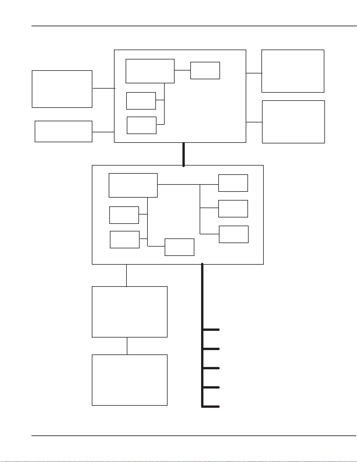
1-1 Block Diagram ...........................................................................................1-2
2-1 Cable connections and mechanical controls..............................................2-5
3-1 Control board test points............................................................................3-2
4-1 First service screen ...................................................................................4-1
4-2 Second service screen ..............................................................................4-2
4-3 Status menu...............................................................................................4-2
4-4 Switch diagnostic diagram .........................................................................4-3
4-5 Pedal screen .............................................................................................. 4-3
4-6 First service screen- diagnostics................................................................4-4
4-7 Servo O2 service screen............................................................................4-19
5-1 Heater housing cover and soffit .................................................................5-1
5-2 Canopy , bracket and heater housing..........................................................5-2
5-3 Canopy seals and extrusions .....................................................................5-3
5-4 Disconnecting door cable...........................................................................5-4
5-5 Upright decorative strips, end caps and wire covers .................................. 5-5
5-6 Removing the lift motor ..............................................................................5-5
5-7 Display module disassembly ...................................................................... 5-6
5-8 Right upright assembly............................................................................... 5-8
5-9 Rollers and tensioning spring .....................................................................5-9
5-10 Replacing the drive belt............................................................................5-10
5-1 1 Replacing the buoyancy springs...............................................................5-11
5-12 Left inner rail ............................................................................................5-12
5-13 Left rail springs and spools ......................................................................5-13
5-14 Re-attaching the upright...........................................................................5-14
5-15 Radiant heater disassembly .....................................................................5-15
5-16 Canopy alignment ....................................................................................5-16
5-17Heater door cable adjustment ...................................................................5-18
5-18 Compartment probe disassembly.............................................................5-19
5-19 Top rail end cap........................................................................................5-19
5-20 Bed disassembly......................................................................................5-20
5-21 Fan motor ................................................................................................5-21
5-22 Heat sink and fan .....................................................................................5-22
5-23 Elevating base .........................................................................................5-23
5-24 Chassis bottom cover ..............................................................................5-24
5-25 Replacing the tilt brake............................................................................. 5-26
5-26 Humidifier parts........................................................................................5-28
iv 08/27/03 6600-0343-000
Page 7

5-27 Display module ........................................................................................5-30
5-28 Probe panel.............................................................................................. 5-30
5-29 Electronics enclosure...............................................................................5-31
5-30 Installing sensors ..................................................................................... 5-33
5-31 Sensor housing ........................................................................................5-34
5-32 V alve housing...........................................................................................5-35
5-33 Endcap safety valve .................................................................................5-36
6-1 Probe Panel Assembly...............................................................................6-1
6-2 Display Module...........................................................................................6-3
6-3 Electrical enclosure....................................................................................6-5
6-4 Humidifier Transformer and Rs232 option..................................................6-7
6-5 Bed ............................................................................................................6-9
6-6 Side panel (E/W)........................................................................................6-11
6-7 Rear (north) and front (south) panel...........................................................6-13
6-8 Radiant Heater...........................................................................................6-15
6-9 Canopy ......................................................................................................6-17
6-10 Heater doors ............................................................................................6-18
6-1 1 Upper chassis ..........................................................................................6-19
6-12 Lower chassis ..........................................................................................6-21
6-13 Humidifier................................................................................................. 6-23
6-14 Base and elevating column ......................................................................6-25
6-15 Right (East) upright, motor side................................................................6-27
6-16 Belt channel -1 (lift motor side).................................................................6-28
6-17 Belt channel -2 (lift motor side).................................................................6-29
6-18 Lift rail (both sides)...................................................................................6-30
6-19 Rail End caps...........................................................................................6-31
6-20 Left (west) upright ....................................................................................6-33
6-21 Compartment Air Probe............................................................................6-34
6-22 Servo Control Oxygen Sensor Housing assembly....................................6-35
6-23 Servo Control Oxygen V alve Housing ......................................................6-36
6-24 Expansion Chamber/Heatsink Vent..........................................................6-37
6-25 Servo Control Oxygen Cooling Fan..........................................................6-37
6-26 Servo Control Oxygen PC board ..............................................................6-38
6-27 Manifold Endcap Safety V alve..................................................................6-38
6-28 Strorage Drawer.......................................................................................6-39
6-29 Instrument Shelf.......................................................................................6-40
6-30 Monitor Shelf............................................................................................6-40
6-31 E Cylinder holder......................................................................................6-41
6-32 Tubing Management Arm.........................................................................6-41
6-33 Dovetail mount DIN rail ............................................................................6-42
6-34 Silo Support .............................................................................................6-42
6-35 Rotating IV Pole Assy. ..............................................................................6-43
6-36 Dovetail extension....................................................................................6-44
6-37 Control board ...........................................................................................6-48
6-38 Display driver board .................................................................................6-49
6-39 Relay board (Rev 10 or higher) ................................................................6-50
6-40 Relay board (Rev 9 or lower) ...................................................................6-51
6-41 Wiring Diagram Control Board .................................................................6-52
6-42 Wiring Diagram Elevating Base and Canopy Lift Rails.............................6-53
6-43 Wiring Diagram Electrical Enclosure........................................................6-54
6-44 Wiring Diagram Graphics Display ............................................................6-55
6-45 Wiring Diagram Incubator (Relay board rev 10 or higher) ........................6-56
6-46 Wiring Diagram Incubator (Relay board rev 9 or lower) ...........................6-57
6-47 Wiring Diagram Radiant heater (Relay board rev 10 or higher)................6-58
6-48 Wiring Diagram Incubator (Relay board rev 9 or lower) ...........................6-59
6-49 Wiring Diagram Servo Humidifier (Relay board rev 10 or higher)............. 6-60
6-50 Wiring Diagram Servo Humidifier (Relay board rev 9 or lower) ................6-61
6-51 Wiring Diagram Servo Control Oxygen .................................................... 6-62
6600-0343-000 08/27/03 v
Page 8

Precautions
wWarnings
Before using the OmniBed, read through this entire manual. As with all medical equipment, attempting to use
this device without a thorough understanding of its operation may result in patient or user injury. This device
should only be operated by personnel trained in its operation under the direction of qualified medical personnel
familiar with the risks and benefits of this type of device. Additional precautions specific to cert ain proce-
dures are found in the text of this manual.
Complete the “Pre-operative Checkout Procedures” section of the Operator’s manual before putting the unit
into operation. If the incubator fails any portion of the checkout procedure it must be removed from use and
repaired.
Do not use the OmniBed in the presence of flammable anesthetics; an explosion hazard exists under these
conditions.
Always disconnect the power before performing service or maintenance procedures detailed in this manual.
Apply power only if you are specifically instructed to do so as part of the procedure.
Thoroughly air dry the incubator after cleaning it with flammable agents. Small amounts of flammable agents,
such as ether, alcohol or similar cleaning solvent s left in the incubator can cause a fire.
wCautions
Only competent individuals trained in the repair of this equipment should attempt to service it as detailed in this
manual.
Detailed information for more extensive repairs is included in the service manual solely for the convenience of
users having proper knowledge, tools and test equipment, and for service representatives trained by Ohmeda
Medical.
vi 08/27/03 6600-0343-000
Page 9

Chapter1- Functional Description
This functional description is divided into four sections representing each of the four boards. The reader
should also reference the block diagram and wiring diagram when studying this section.
1.1 Control Board
The Intel 80C188EC microcontroller is an enhanced X86 processor with many on-board peripheral features,
such as a interrupt controller, DMA controller, peripheral chip select driver, programmable timers, etc. The two
programmable timers are used to control the two heaters (bed and radiant). The input to these timers is line
frequency . This allows the control signal to be synchronized with the line frequency to better control the zerocrossing solid state relays. The on-board interrupt controller has several interrupts: analog-to-digital converter
(ADC) conversion ready signal, overtemperature comparator output, watchdog output, power fail signal, and
module interrupt signal from the system data bus. The microcontroller external bus is a multiplexed address
and data bus.
The system memory consists of a programmable read-only memory (PROM) and static random access
memory (SRAM). The EEPROM is used for calibration values and infrequently changing variables. This
memory holds the data even after power is turned off.
The RS-485 integrated circuit converts the RS-232 TTL signals from the microcontroller to RS-485 signals for
the bus. This bus is the main communications bus from the control board to all other boards with processors.
There are two isolation transceivers used to isolate the circuits powered by +5V and the circuits powered by
+5VSTBY (battery backup).
The board contains a 16 channel multiplexer. There are seven temperature measurement channels. These
channels measure the two patient probes with two thermistors each, the two air temperature thermistors used
for display and control, and an additional thermistor used to measure the heat sink temperature.
Additional channels include the humidity sensor (RHIN), LINE COMP & LINE COMP2, 5 V olt s, Motor current,
Vthref, VDAC, and 1.2Vind.
Attached to the environmental probe connection is the relative humidity signal conditioning circuitry. The 1V
reference that is used for the analog circuitry is also the maximum input voltage and the offset voltage for the
ADC. This yields a purely ratiometric system.
The overtemperature circuit compares the air temperature to a reference level, generates an interrupt, and
turns off the heat if the air temperature is higher than the reference level. The overtemperature circuit requires
varying its voltage levels to accommodate various thermistor measurements. This is because the calibration is
digital (no potentiometer).
The watchdog circuitry monitors the 80C188 microprocessor, and monitors the +5V and +5VSTBY voltages. It
generates the interrupt signal and power failure signal to the 80C188 microprocessors. The audio circuit
includes a 8752 microcontroller that reads a wavetable located in a PROM and sends the table to a digital
audio circuit and amplifier. The high priority (HP) and other alarm signal lines select an output at the correct
frequencies.
Three OR gates are combined to generate the error signal. The inputs to the circuit are overtemperature,
power failure, and system failure. This circuit generates an error signal that turns off the heater and sounds the
HP alarm. This circuit is independent of the microcontroller.
6600-0343-000 08/27/03 1-1
Page 10
Chapter 1- Functional Description
LED Board
EL Display
Microprocessor
PROM
SRAM
Microprocessor
PROM
SRAM
Audio
Time
Display Driver Board
Temp
Channels
Overtemp
Watch
Dog
Membrane Switches
Knob
Figure 1-1
Block Diagram
Control Board
Relay Board
RS485
Future Options
and
Modules
Power Supply
1-2 08/27/03 6600-0343-000
Page 11

Chapter1- Functional Description
1.2 Relay Board
The Relay Board includes 2 safety relays, which close to supply mains power to the heater and motor circuits.
Safety relay 1 is wired in series with the primary coil of the isolation transformer for the incubator and radiant
warmer heaters. Safety relay 2 closes the mains supply to the humidifier isolation transformer and the transformer for the e-base and canopy motors. Control signals for the two relays originate on the Control Board.
The Relay Board interfaces the DC control signals to the two chassis mounted solid-state relays (SSRs), which
control the incubator and radiant warmer heaters individually . The control signals for the two heater SSRs
originate on the Control Board.
The Relay Board includes a SSR for the humidifier. The SSR output is wired in series with the humidifier
heater. The humidifier SSR control signal originates on the Control Board.
There is one current sense circuit for the incubator and radiant warmer heaters and an additional one for the
humidifier heater. These circuits consist of a small signal transformer that produces a current proportional to
the current through the heater circuits. The current is rectified and measured. The subsequent comparator
then generates a digital level based on a specified current level. This results in a signal to the Control Board
representing the state of the heater (on or off).
The two line compensation circuits consist of a signal transformer connected to the mains voltage. The
secondary of this transformer feeds a full wave rectifier and capacitor . The resulting DC voltage is proportional
to mains voltage, and it is measured on the Control Board.
The line frequency circuit consists of a full wave rectifier and a comparator . This circuit generates a digit al
pulse with frequency twice that of the line frequency (50 or 60 Hz). The output signal is provide to the Control
Board.
The Relay Board provides the +5v standby power supply to the entire Giraffe system. A +5V regulator generates the +5V standby from the diode OR combination of the system +12V power supply or the backup battery .
If there is no mains power, then +12v is not present, and the battery will generate the +5V st andby. When
+12V is present, the battery is biased out of the circuit with the diode and is merely being trickle charged
though a resistor.
The motor driver circuit turns the DC motor coils in the incubator airflow fan motor on and off based on feedback from the hall effect position sensors. This integrated circuit can also vary the speed and brake the motor
based on input signals from the Control Board.
The airflow sensor consists of an opto-coupler that outputs a clocking pulse proportional to the fan movement.
The signal is AC coupled to eliminate of fset voltages and drif t s. The resulting pulse is half wave rectified and
stored in a capacitor to yield a DC voltage proportional to the fan speed. If the fan stops or there is no fan, this
DC voltage becomes zero. The output signal is provide to the Control Board to indicate proper airflow motor
operation.
The hood lift and elevating base circuit consists of a series of relays that apply voltage to the hood lift motor or
the elevating base motor. The hood lif t motor is driven at 30V going up and 15V going down. The e-base
motor is always driven at 30 volts. The motor current sense circuit consists of a small signal transformer that
produces a current proportional to the motor current. The transformer output current is converted to a voltage
and filtered. An output volt age indicative of the motor current amplitude is provided to the Control Board. A
subsequent comparator then generates a digital level based on a specified current level. This results in a
signal to the Control Board indicating whether or not the e-base motor is stalled.
The Relay Board interfaces the user and system status input switch signals to the Control Board. Switch
signals include, e-base & canopy activation, canopy and heater door position, and humidifier reservoir and
water level status.
6600-0343-000 08/27/03 1-3
Page 12

Chapter 1- Functional Description
1.3 Display Driver Board / EL Display
The Display Driver board contains the same Intel microcontroller as the Control board. The processor on the
display board is used to control the EL display contents and monitor user inputs received from the membrane
switch panel and rotary encoder knob.
There are two groups of digital inputs: membrane switch panel and rot ary encoder knob. The membrane
switches are pulled high; pressing the switch grounds the input. The encoder also has a switch, and two
optically isolated lines that pulse out of phase with each other. The number of pulses represents the number
of steps the knob rotates. The phase of the pulses represents the direction of the knob rot ation.
The display board system memory consists of a programmable read-only memory (PROM) and static random
access memory (SRAM).
The RS-485 integrated circuit converts the RS-232 TTL signals from the microcontroller to RS-485 signals for
the bus.
The timekeeping RAM has a battery integrated into the chip so that the time and date run are kept current
even with the power off. The battery has a minimum life of 10 years.
The graphics controller is an S-MOS VGA controller. The graphics controller interfaces the data from the video
RAM to the EL display. The controller also synchronizes the display using a horizontal pulse (LP) and a
vertical pulse for the whole display frame (YD). The controller handshakes with the 80C188 using the READY
line to eliminate any lost data during display refreshes.
1.4 LED Board
The LED Board contains five display banks and two display drivers. One of the display drivers controls the
patient temperature and air temperature display banks. The other driver controls the patient set temperature,
air set temperature, warmer bar graph, and the mode and override indicators.
This allows the two large displays (patient and air temperature) to be multiplexed at a slower rate than the
other LEDs. This results in brighter large displays. Each driver has a brightness potentiometer that is preset
at the factory and should not be adjusted in the field.
1.5 Power Supply
The universal input switching power supply converts the line voltage to +5V DC and +12V DC. This supply can
source up to 75 watts. The 5 volts powers the electronics and the 12 volts is used by the EL display and for
future boards.
1.6 Peripheral Components
There are several peripheral components. The isolation transformer isolates the radiant heater from the line
voltage.
The toroidal transformer bucks the line voltage to the range of the elevating base and the canopy lift drive
system.
The humidifier isolation transformer isolates the humidifier heater from the line voltage.
The solid state relays mounted to the chassis are used to control the radiant and bed heaters.
1-4 08/27/03 6600-0343-000
Page 13

Chapter1- Functional Description
1.61 Rail and Heater Door Switches
There are seven switches used to determine the position of the canopy and the heater doors.
Two normally open switches on each heater door determine the position of the doors. Each switch is wired in
series with the corresponding switch on the other door. One p air of switches closes only when the doors are
fully open and the other pair closes only when the doors are fully closed.
There are 3 normally open switches in the right upright which are used to determine the position of the canopy .
The top switch closes when the canopy reaches the upper position. The middle switch detects downward
movement of the canopy . The bottom switch closes when the lowest position is reached.
The radiant heater will turn on only if the two heater door open switches and the top rail switch are all closed.
The system will control as an incubator only if the bottom rail switch and the two heater door closed switches
are all closed.
As the canopy lowers the system senses the closure of the middle rail switch, then looks at the heater door
closed switches. If they are not closed the canopy will return to the highest position. This insures that the
canopy will not lower to the lowest position if the heater doors are not closed.
1.7 DataLink Option
The DataLink option allows direct output of serial data to various remote monitoring systems, such as a
computer or commercial RS-232 monitor. The Dat aLink option board cont ains the electronic circuitry necessary to provide a 2500 VRMS isolated serial interface to meet the logic levels specified by EIA RS-232D and
CCITTV.28.
The MAX250 and MAX251 (U1 and U2), together with two 6N136 optocouplers and transformer TR1, form an
isolated RS-232 transmitter and receiver. The MAX250 connect s to the non-isolated or “logic” side of the
interface, translating logic signals to and from the optocouplers, while the MAX251 resides on the isolated or
“cable” side, translating data between the optocouplers and RS-232 line drivers and receivers. In addition to
the optocoupler drivers and receivers, the MAX250 also contains isolation transformer drive circuitry which
supplies power to the isolated side of the interface, and the MAX251.
The transmit signal is input to the MAX250 driver (U1 pin 4) whose output (U1 pin 3) drives optocoupler U4.
The optocoupler output (U4 pin 6) is then fed into the MAX251 driver (U2 pin 3). The output of the MAX251
driver (U2 pin 12) is at the logic levels conforming to EIA RS-232D and CCITTV.28. Conversely, the receive
signal enters the MAX251 driver (U2 pin 10) and is stepped down to CMOS/TTL levels at U2 pin 5. This logic
level drives optoisolator input (U3 pin 3) whose output is fed into U1 pin 10. The output (U1 pin 9) signal is then
available to the control printed circuit board.
A slide switch SW1 is used as a “self test” for the RS-232 interface. In the closed position, the J30-1 transmit
signal is sent through the MAX250/MAX251 transmitter and back into the receiver portions. The signal can be
read at J30-2 and verified to be correct. Any external cable connection must be removed for this self test to
function. CR1 and CR2 provide transient protection for MAX251. In normal operation SW1 should be in the
open (OFF) position.
The nurse call signal is input at J30-5 as a TTL logic level. In the “no alarm” st ate, this signal is a logic high,
which turns on Darlington Q1, energizing relay K1. This results in contact closure between J31-1 and J31-2. In
the “alarm” state, J30-5 is a logic low , which turns of f Q1, de-energizes K1 and results in cont act closure
between J31-2 and J31-3. K1 provides 2500 VRMS isolation between the relay coil inputs and contact outputs.
6600-0343-000 08/27/03 1-5
Page 14

Chapter 1- Functional Description
1.8 Servo Controlled Oxygen Option
The Giraffe Servo Control Oxygen System consists of an oxygen sensing circuit, Servo Oxygen circuit board,
and an oxygen delivery system.
The sensing circuit is located beneath the bed and consists of a pair of fuel cell oxygen sensors, a three-way
solenoid calibration valve, and a calibration fan. In normal operation the calibration valve is closed and allows
the Giraffe fan to circulate gas from the infant compartment across the sensors.
The unit must be calibrated at least every 24 hours when servo oxygen is in use. Af ter 24 hours have elapsed
the system prompts the user to perform calibration. Once the operator initiates calibration, the calibration
valve opens and the calibration fan is turned on. This draws ambient air across the sensors until a stable
reading is obtained. This 21% oxygen reference value is then used to calibrate the measuring algorithm. After
calibration 100% oxygen is briefly delivered to the system to ensure there are no occlusions. When calibration
is complete the unit will resume controlling oxygen based on the last set point.
The system must have two sensors present to operate. One sensor is always used for control and the other is
used for a redundant check and display . The sensors generate a volt age of about 40 millivolt s at 21% oxygen
concentration and about 200 millivolts at 100% oxygen concentration. The voltage is directly proportional to
the concentration of oxygen. Humidity and temperature sensors located in the sensor plug are used for
voltage compensation. A fan mounted to the sensor-housing door is activated when the temperature reaches
50 degrees C. This fan circulates air to keep the sensors below the maximum allowable operating temperature, about 55 degrees C.
The Servo O2 board is located in the Giraffe controller enclosure. The microcontroller and integrated EPROM
on the board perform the following:
Convert sensor output from analog to digital
Activates oxygen alarm conditions.
Two-way communications via 485 bus with the Giraf fe control board.
Controls the calibration valve to select calibration mode.
Controls the two supply valves to maintain the desired oxygen set point.
Opens the safety relay , which removes power to the three-way valve and the supply valves in case of
a system failure.
The oxygen delivery system consists of two solenoid supply valves, and a regulator assembly . The preset
regulator regulates the oxygen supply to 345 kPa (50 psi). T wo supply valves, controlled by the Servo Oxygen
board, control flow to the infant compartment. Both valves are opened until the measured level gets close to
the desired set point then one valve is closed. One valve is then cycled on and off as needed to maintain the
desired oxygen levels in the infant compartment. The valve selected is alternated so both valves cycle about
the same number of times. There are 2 fuses between the Servo O2 board and the supply valves that prevent
high current from the board entering the valve housing should a short occur in the supply valves. A safety valve
that shuts off oxygen flow whenever the canopy is raised actuates mechanically by the movement of the
canopy support rail. When the canopy is down the valve is open (canopy up/valve closed). The safety valve
actuates independently of the solenoid type supply valves.
1-6 08/27/03 6600-0343-000
Page 15

Chapter 2- Service Checkout
2.1 Setup
The OmniBed is shipped with the canopy in the locked down position. Before the canopy can be raised the rail
shipping locks must be released. They are located in both sides of the OmniBed near the outside bottom of the
uprights. An orange tear-away label marks their location. The lock consists of a socket head cap screw in a
slot. Tightening the screw disengages the screw head from the slot and releases the lif t rail. Using the 4 mm
hex key provided with the unit, turn the screw clockwise about 8 rotations until the screw securely seats in its
hole. Remove the tear away label.
WARNINGS w Do not perform the preoperative checkout procedure while the patient occupies the
unit.
w Complete the preoperative checkout procedure section of this manual before
putting the unit into operation. If the equipment fails any portion of the checkout
procedure it must be removed from use and repaired.
2.2 Mechanical checks
1. Disconnect the power cord for the mechanical portion of the preoperative checkout procedure.
2. Examine the power cord for any signs of damage. Replace the cord if damage is evident.
3. Check that both plug retaining brackets are in place.
4. Examine the unit overall for any damaged or missing parts.
5. Check that all the casters are in firm contact with the floor and that the unit is stable. Lock the caster
brakes and check that they hold the unit in place. Release the brakes and check that the unit moves
smoothly.
6. Check the operation of the two side doors. Open the doors and check that they swing all the way down
and hang perpendicular to the bed. Check that the doors are securely attached to the unit and that the
hinge pins are properly seated. Check that the inner walls are securely fastened to the doors. Close the
doors and check that the latches hold the doors securely shut. The orange latch open indicators should
not be visible when the latches are engaged. Check that the top of the doors meet the canopy seal.
7. Check the portholes. Open the portholes by pressing on the latch. The cover should swing open. Close the
porthole and check that the latch holds the cover securely shut and that the cover seals tightly against the
porthole gasket. Check that all the porthole seals are in place and are in good condition.
8. Check that the tubing access covers in the four bed corners and the large slot grommet at the head of the
bed are in place and are in good condition.
9. Check the operation of the bed. The bed should rotate easily without binding. If the bed is properly seated
and locked in place, the mattress should be level. With the bed rotated back into the straight position,
check to see that the bed platform extends and stops when it is pulled out on either side. Check the
operation of the bed tilt mechanism. Squeeze the tilt control and push down on the foot of the bed. The
head of the bed should raise easily , and should stay in position at any angle along it s tilt p ath when the tilt
control is released. Push down on the head of the bed. The foot of the bed should raise easily, and should
stay in position at any angle along its tilt path when you the tilt control is released.
6600-0343-000 08/27/03 2-1
Page 16

Chapter 2- Service Checkout
2.3 Controller checks
WARNING w Do not use the OmniBed in the presence of flammable anesthetics: an explosion
hazard exists under these conditions.
1. Connect the OmniBed power cord to a properly rated outlet.
2. Connect the patient probe to jack 1 on the probe panel.
3. Switch on the power at the mains switch on the back of the unit, and at the standby switch on the jack
panel, while holding in the override button (>37) on the control panel during power up until the software
revision screen appears. Release the button and the first service screen will appear.
4. Scroll to “Down” and select it to bring up the second service screen. Select Status to see Status screen.
Check status of the software self tests. These include: incubator heater on (INCHTRON), warmer heater
on (WRMHTRON), incubator/warmer heater off (I/WHTROFF), humidifier heater on (RHHTR), remote
monitoring data stream (RS232LOOP), incubator fan on (F ANON), and incubator fan off (FANOFF). All
test should say P ASS except RS232 LOOP (the connector pins must be shorted to get the PASS message).
5. Using the standby switch turn off the unit, then turn it back on.
Verify the following:
➺ All the displays and indicators light
➺ The software revision appears
➺ The prompt tone begins
Note: If the unit has been used in the last 2 hours, the patient history query appears.
6. Adjust the set temperature to silence the prompt tone.
7. Check the patient probe. If the probe is below 30 C, the display will show -L-. Warm it by placing it between
your fingers, and verify that the baby temperature reading increases.
8. Unplug the patient probe and check that both visual and audio alarms trigger in the Baby control mode.
9. Check the canopy lift mechanism. Push the lift pedal and verify the canopy raises smoothly in one continuous movement to its upper limit, the heater doors open, and the unit shifts into warmer operation. Check
that the pedals on both sides of the unit raise the canopy .
10. With the canopy raised, check the operation of the panel at the foot of the bed. Check that after you lift up
on the panel, it swings down and hangs perpendicular to the bed. Check that the panel is securely attached. Check that it swings back up and seats in the closed position.
1 1 . Lower the canopy and verify that it stops when you remove your finger from the hand switch. Check that it
stops automatically at its lower limit, and that the canopy seal makes contact with all four bed sides, and
that the unit shifts into the incubator operating mode. Check that the raise and lower buttons at the head of
the bed on both sides of the unit raise and lower the canopy .
12. If so equipped, check the operation of the bed elevating system. Raise and lower the bed along its entire
travel range, checking that the mechanism operates smoothly . Check that the pedals on both sides of the
unit raise and lower the bed.
13. Check the power failure alarm and the battery backed up memory. Make note of the current control mode
and temperature settings and wait one minute, then unplug the OmniBed from the wall outlet. An alarm
2-2 08/27/03 6600-0343-000
Page 17

Chapter 2- Service Checkout
should sound and the power failure indicator should light. Wait one to two minutes and plug the OmniBed
back in. Verify that the alarm cancels and that the OmniBed returns to the same control mode and temperature settings it displayed before the power interruption.
Note: A fully charged battery should supply the power failure alarm for approximately 10 minutes. If the
alarm is tested for the full 10 minutes the OmniBed must be run at least two hours to recharge the battery
before it is used with a patient. Total recharge time is 8 to 10 hours.
14. Perform the Leakage Current and Ground Resistance checks in Chapter 3 of this manual.
2.4 Humidity check
Turn on the Giraffe unit and verify that the Servo Humidity icon is on the screen. Set the Humidity to 65%. Wait
for 4 minutes. If no alarms are seen (except for a possible “Add Water” message) the humidifier is operational.
Note: It is not necessary to have water in the reservoir to perform this test.
2.5 Servo Controlled Oxygen check
Leak Check
This test checks for leaks between the O2 sensors and the Heat sink vent fitting.
1. Remove translation deck, tilt platform, upper pan, and fan.
2. Cover the heat sink vent near the fan shaft with adhesive tape. Make sure the tape will not interfere with fan
rotation. Reinstall the fan, upper pan, tilt platform, and translation deck.
Note: If the conical shaped rubber grommet was removed with the fan, when reinstalling fan be sure that
rubber grommet clicks into groove on fan shaft.
3. Power up the unit, hold down the ‘Air curtain’ button and press the ‘Down’ button to force the Giraf fe into low
fan speed.
4. Set O2 set point to 21%; the display will show the actual concentration in the larger numerals next to the set
point. Open the doors until the actual concentration reaches 21% (ambient).
5. Run the Servo O2 calibration routine and wait for the calibration complete message. In approximately 20
seconds, the “Check O2 Supply” alarm should sound. If there is no alarm, the tubing between the sensor
housing and the heat sink vent fitting has a leak or is disconnected. Repair the leak and repeat steps 1
through 4 of this procedure.
6. After performing the test, power off the unit. Remove the translation deck, tilt platform, upper p an, and the
fan, and remove the adhesive tape. Be sure to remove any residue on the heat sink left by the tape.
7. Reassemble the system and run the calibration routine one final time.
Pre-use Checkout
This test checks for leaks between the chassis vent fitting and the O2 sensors.
1. Connect an acceptable hose from an oxygen supply to the oxygen inlet fitting on the unit. Supply pressure
should be between 310 kPa (45 PSI) and 586 kPa (85PSI).
2. Select wrench icon on display screen to bring up setup menu. Select Cal Oxygen on the setup menu to
initiate calibration.
6600-0343-000 09/09/03 2-3
Page 18

Chapter 2- Service Checkout
3. When calibration is completed, 100% oxygen is delivered for approximately 20 seconds to ensure there
are no occlusions in the system. Do not turn off the unit or disconnect the oxygen supply during this brief
period after the ‘Calibration Complete’ screen appears. Exit calibration screen.
4. Select O2 icon on display screen to bring up Servo Control Oxygen menu. Hold down the ‘Air curtain’
button and press the ‘Down’ button to force the Giraffe into low fan speed.
5. Set O2 set point to 65%. Start timer and verify that unit reaches 60% in less than 10 minutes. If rise time is
longer than 10 minutes check all tubing between the O2 sensors and the chassis vent fitting.
Note: The chassis vent may be identified by its mushroom cap shaped cover .
Supply Valve Leak Test
1. Connect oxygen supply to Servo Oxygen fitting.
2. Disconnect the 10mm hose from the expansion chamber .
3. Power up unit in Service Mode.
4. The canopy should be closed for this step and step 5. Scroll to Servo Oxygen service screen, and open V1
& V2 and verify that gas flows audibly .
5. Close V1 & V2 and place the 10mm hose in a cup of water. Verify that no more than 10 bubbles appear
over a one minute period. If unit fails, replace supply valves.
6. Raise the canopy a couple of inches and open V1 & V2. Verify that no more than 10 bubbles appear over
a one minute period. If unit fails replace two-way valve or spring assembly .
When test is completed, reattach 10 mm hose to expansion chamber.
2.6 Accessory checks
1. Check that all accessories are securely mounted and out of the path of the canopy .
2. Check the operation of any accessories with reference to their appropriate operation manuals.
3. Setup any required suction or gas supply systems. Check them for leaks as described in their respective
operation manuals.
2-4 08/27/03 6600-0343-000
Page 19
Chapter 2- Service Checkout
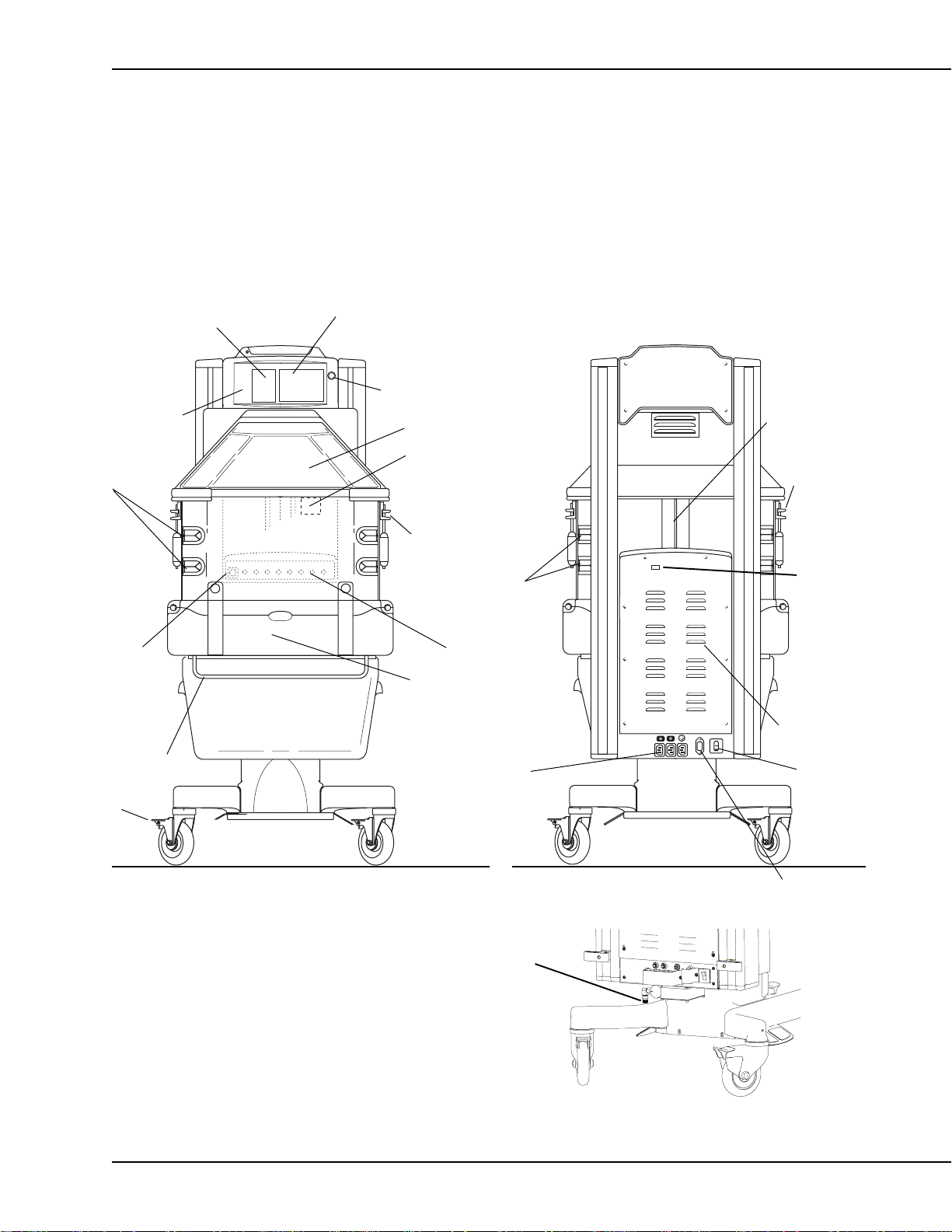
2.6 Cable Connections and Mechanical Controls
Numeric Temperature Displays
Temperature
Regulation
Controls
Tubing Grommets
Standby
Power
Switch
(I/O)
Drainage
Hanger
Caster
Brake
Graphics Screen
Control Knob
Canopy
Compartment Probes
Side Door Latch
Tubing Grommets
Humidifier Reservoir
(air intake filter located
behind reservoir)
Accessory
Power Outlets
Ventilator
Slot
Side Door
Latch
RS 232
Connector
Probe Jacks
Controller
Cover
Mains Power
Switch
FRONT
Figure 2-1
Connections and controls
6600-0343-000 08/27/03 2-5
O2 connection for
Servo Controlled Oxygen option
Plug retaining brackets
not shown for clarity
BACK
Power
Cord
Inlet
Page 20
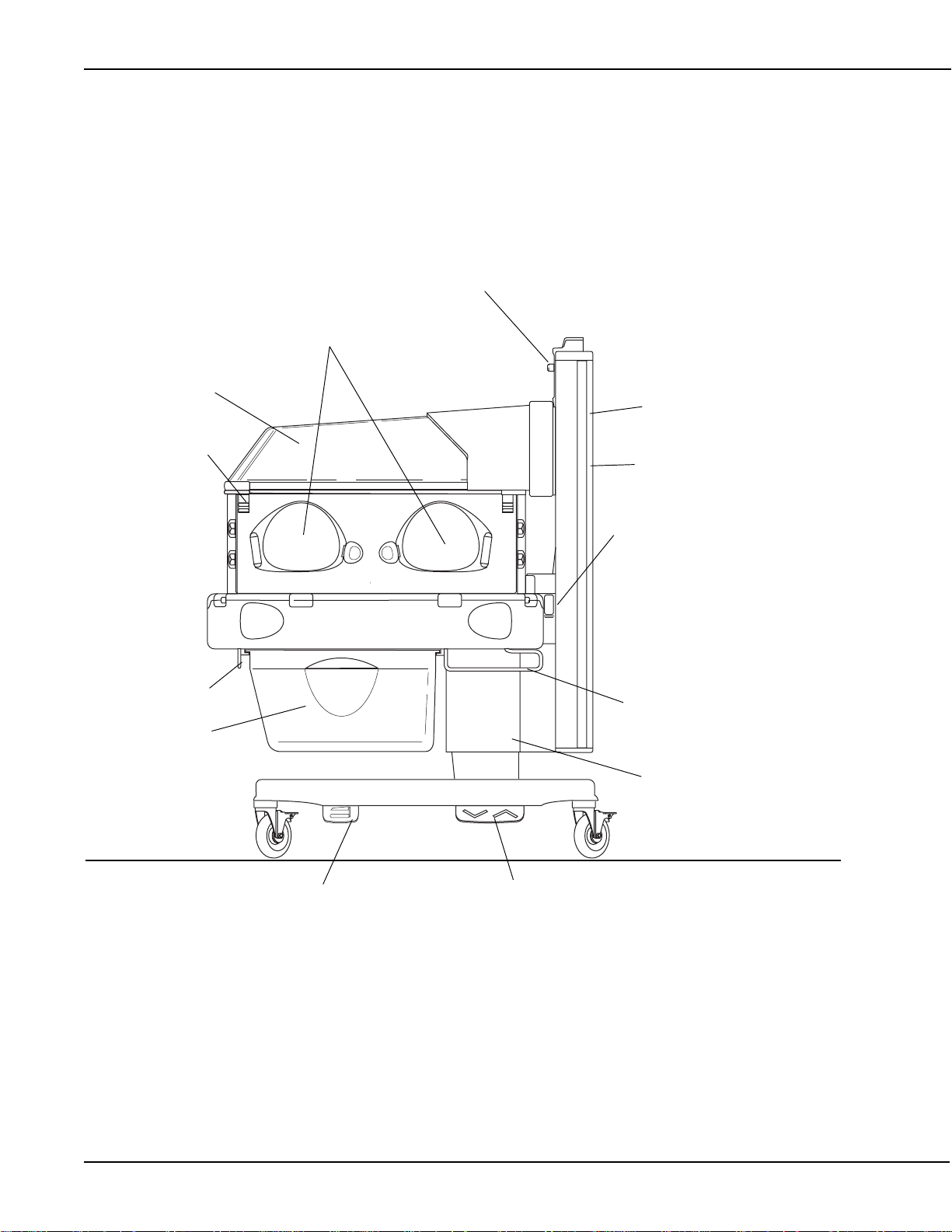
Chapter 2- Service Checkout
Portholes
Canopy
Control Panel
Upright
Side Door Latch
Drainage
Hanger
Storage Drawer
Raise Canopy Pedal
SIDE
Dovetail rail
Canopy Raise/Lower Switches
Pleural Drainage Hanger
Elevating Column
Bed Height Pedal
2-6 08/27/03 6600-0343-000
Page 21

Chapter 3- Calibration and Maintenance
Use Static Control W ork Station to help ensure static charges are safely conducted to ground.
The velostat material is conductive; do not place electrically powered boards on it. Whenever
this symbol appears beside a procedure, take static control precautions.
WARNING w Af ter performing any rep air or calibration, always perform the Service Checkout Proce-
dure before putting the unit back into service.
3.1 Maintenance schedule
The unit should be maintained in accordance with the procedures detailed in this manual. Service maintenance must be performed by a technically competent individual.
Service maintenance
This schedule lists the minimum frequencies. Always follow hospital and local regulations for required
frequencies.
Annually
Perform the electrical safety and calibration procedure as described in the service manual.
Calibrate the scale.
If unit is equipped with Servo Controlled oxygen:
Replace vent screen.
Perform supply valve leak test.
Replace sensors*. It’s recommended both sensors be replaced at the same time.
*
Sensor life of one year is approximate. If the sensor is used often at high oxygen concentrations, sensor life will decrease.
Every T wo Years
Replace the battery .
Note: The battery is used to sound the power failure alarm and to power memory circuits during a
power failure.
Every Three Y ears
Calibrate the humidifier.
3.2 Special Tools
The following tools (or their functional equivalents) are required to complete the recommended
service procedures:
Digital Multimeter , 4-1/2 digit
Leakage Current Tester
PLCC Extractor for removing socketed chips
Static Control Work Station (recommended)
Light gray touch-up paint (Munsell .16GY8.56-0.44 chroma)-18ml ........6600-0714-200
Servo Humidity Calibration Kit................................................................6600-0048-850
Scale calibration weight- 5kg .................................................................6600-0209-800
6600-0343-000 08/27/03 3-1
Page 22
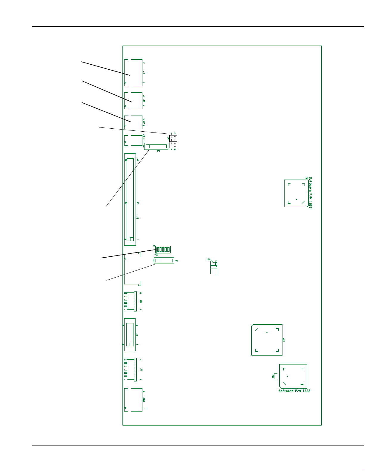
Chapter 3- Calibration and Maintenance
J1
J4
J2
Calibration jumper
NORMAL
MODE
CAL
MODE
Test Point 1
Dipswitch
Test Point 2
12345678
Figure 3-1
Control board test points
3-2 08/27/03 6600-0343-000
Page 23

Chapter 3- Calibration and Maintenance
3.3 System Calibration
Note: If Only performing line voltage calibration, follow instuctions in next section, 3.4.
Important: Be sure to perform System Calibration after replacing a control board.
1. Turn power off.
2. Remove electrical enclosure back panel.
3. Unplug the temperature sensors and from J1, J4 and J2 on the control board.
4. Move jumper JP1 to the CAL MODE position on the control board (see Figure 3-1). Be sure to orient the
jumper correctly so pins 5-6 and 7-8 are shorted.
5. Turn power on. After running the power-up testing INITIALIZING will be displayed and dots will move
across the top of the screen.
6. After about 90 seconds CALIBRATION MODE, Enter “VREF”, and Enter “Mains” will be displayed.
7. Using a 4 ½ digit DVM (capable of measuring to 0.1 millivolt) measure VREF at TP1, pins 1 and 6 (pin 6 is
ground) on the control board. Measure to the nearest 0.1 millivolt.
8. Dial in VREF using the control knob. Press the knob to enter the value.
9. Measure the Mains Voltage at the AC connectors at the bottom of the electronics enclosure cover .
10. Dial in the Mains voltage using the control knob. Press the knob to enter the value.
11. After a few seconds the dots will stop moving across the screen and DONE will appear on the top right of
the display . Do not shut of f the unit until the DONE message is displayed or the new calibration values will
not be stored.
If the message “Mains voltage calibration failed. Please enter the mains voltage again” appears this
indicates the dialed in line voltage is 20% different than the measured value (not the nominal value).
12. Power down the unit and move the calibrate jumper to the NORMAL MODE position. Be sure to orient the
jumper correctly so pins 1-2 and 3-4 are shorted. Reconnect J1, J4 and J2 on the control board.
3.4 Line Voltage Calibration
Important: Be sure to perform line voltage calibration after replacing a relay board.
1. Hold the overide button (>37) while powering up the unit to enter the service screen.
2. On the second service screen select CAL LV.
3. Measure the line voltage at the AC connectors located at the bottom of the electrical enclosure.
4. On the CAL LV screen, dial in the mains voltage value that you measured and push the knob to enter it.
5. When calibration is completed screen will say Mains Volt age Calibration Complete.
If the message “Mains voltage calibration failed. Please enter the mains voltage again” appears this
indicates the dialed in line voltage is 20% different than the measured value (not the nominal value).
6600-0343-000 08/27/03 3-3
Page 24

Chapter 3- Calibration and Maintenance
3.5 Humidifier Calibration
Important: Be sure to re-calibrate the humidifier whenever either the sensor or the control board is
replaced.
Important: In order for the water in the calibration bottle (6600-0048-850) to be completely saturated, most
of the salt should not be dissolved. There should be as little standing water above the salt line as possible
to minimize the response time. The salt in the calibration bottle may only be used for a period of one year
after it’s initial mix with water then the kit should be discarded.
1. Take the cap off the humidity calibration bottle and add one half cap full of distilled water to the bottle.
Shake the bottle to thoroughly mix the salt and water solution. Place the smaller end the elbow over the
bottle.
2. Slide the elbow over the humidity sensor (mounted on the back wall) until it stops. This creates a 75% RH
environment for the sensor.
3. Hold the override key while powering up to enter the service screen.
4. On the second service screen, select Cal RH. The screen will prompt “Push knob when RH reading is
stable.” Wait for 20 minutes or until the RH display st abilizes (does not change by more than 1% in 5
minutes).
5. Depress the control knob to complete the calibration. On software revision 1.3 and higher , you will have
the option to select ST ABLE, SET TO DEFAULT or EXIT. STABLE initiates calibration. SET T O DEFAUL T
resets calibration values back to factory default settings. If you started calibration by mistake (without the
calibration bottle in place, for example) you would select SET TO DEFAULT and then calibrate the unit. If
you have entered the calibration routine by mistake, select EXIT to leave without initiating calibration.
6. If “RH Sensor Calibration Completed.” is displayed the calibration is complete. Depress the knob to exit
the Cal RH routine.
7. If “RH Sensor Calibration Failed. Try Again.” is displayed verify your setup and press the knob to try the
calibration again. This message appears if the signal from the RH sensor is outside the values expected
from the sensor at 65-85% RH. If the failure persists it means the readings are out of this range and either
the calibration bottle or the RH sensor may be defective.
3.6 Servo Controlled Oxygen Calibration
1. Select Set Up icon (wrench) to bring up Set Up screen.
2. Scroll down and select Cal Oxygen to initiate calibration. Calibration is automatic and takes less than five
minutes. A bar graph indicates progress toward completing calibration. If for any reason you wish to
discontinue calibration before it is completed, turning the control knob in either direction will cause the
word Cancel to appear on the calibration screen. Pushing in the control knob will discontinue calibration.
When calibration is completed, 100% oxygen is delivered for approximately 20 seconds to ensure there
are no occlusions in the system. Do not turn off the unit or disconnect the oxygen supply during this brief
period after the ‘Calibration Complete’ screen appears.
Note: The servo control oxygen system prompts for calibration every 24 hours, but the system may prompt for
calibration if there is a large leak in the system (for example if a door is open) for half an hour.
CAUTION w The servo-control system must be calibrated at the same atmospheric pressure in which it is
to be used. Operation at atmospheric pressures other than that present during calibration may
result in readings outside the stated accuracy for the unit.
3-4 08/27/03 6600-0343-000
Page 25

Chapter 3- Calibration and Maintenance
3.7 Scale Calibration
NOTE: The scale is calibrated using a Class F calibration weight between 1 kilogram and 8 kilograms
(accuracy of 0.01%).
1. Place the test weight on the center of the bed.
2. Hold the override key while powering up to enter the service screen.
3. On the second service screen, select Cal Scale.
4. Remove the weight and push the knob at the screen prompt “REMOVE THE WEIGHT AND PUSH
KNOB”. The screen will prompt “INITIALIZING......” for a few seconds.
5. Replace the weight and push the knob at the screen prompt “PLACE TEST WEIGHT AND PUSH KNOB”.
The screen will prompt “MEASURING ....” for a few seconds
6. When the screen prompts “ENTER TEST WEIGHT” Dial in the test weight to the nearest gram. Press the
knob to enter. The screen will prompt “CALCULATING.” for a few seconds.
7. When the screen prompts:
SA VE AND EXIT
EXIT ONLY
RESTORE DEFAULT
Select and enter “SA VE AND EXIT”
8. Turn off the power to exit the service mode.
3.8 Leakage Current
Use approved equipment and techniques to test the unit’s leakage current and ground continuity. Follow the
directions supplied by the test equipment manufacturer to verify the following:
1. Less than 300 microamperes measured at any exposed metal surface for equipment rated at 120 Vac, 50/
60 Hz.
2. Less than 500 microamperes measured at any exposed metal surface for equipment rated at 220 Vac, 50/
60 Hz or 240 V ac, 50/60 Hz.
3.9 Ground Resistance Check
Measure the resistance between the ground pin on the line cord plug and exposed metal of the electronic
enclosure. The ground resistance must be less than 0.2 ohms.
6600-0343-000 08/27/03 3-5
Page 26

Chapter 3- Calibration and Maintenance
3-6 08/27/03 6600-0343-000
Page 27

Chapter 4-Troubleshooting
4.1 Service Screen
To access the service screen, hold in the override button (>37) during power up until the software revision
screen appears. Release the button and the first service screen will appear.
Figure 4-1
DAC Volt 0.000
Language English
Temp U C
Volume Maximum
Pat Alarm 1.0C
Elevate Enable
Pat Ctrl Both
Pat Algo Cascade
Preheat 25%
Canopy Enabe
Scale U gms
Scale R 10g
Comfort Enable
Set Time
View Mods
Down
HFS 1500
LFS 1000
RH 50
SR 1548
SC 21279
Last Cal: 1/1/02 Fri 3/3/03 9:54am
ADT 22.66
ACT 22.65
P11 327.67
P12 327.67
P21 327.67
P22 327.67
HSP 18208
LV1 117.4
LV2 117.8
LF 60
MC 0.001
TV 1.648
5V 5.059
VR 1.233
DV 0.000
BV 0.000
First service screen
Default options that may be selected from this screen appear along the left side of the screen
DAC Volt Digital/Analog Converter voltage. This is the over temperature voltage that is used by the
system to verify the computer independent circuitry is working. To manually test this circuit
enter voltages from 0 to .5 V. The DV value at the bottom right corner of the screen should
match this value within 10mV.
Language English is the default language that appears on the EL screen, but you can select French,
Spanish, etc., depending on what software is installed.
Temp U Changes temperature displays to show Fahrenheit, Celsius or Celsius Only so the
Fahrenheit option is not present on the user Set-up screen (Celsius is factory set default).
Volume Select one of four volume settings. 1 is minimum, 4 is maximum.
Pat Alarm Set the default Baby Hot/Baby Col alarm to activate when either 0.5ºC or 1.0ºC difference
is read between a set temperature and the baby probe temperature.
Elevate Disable or enable the elevating column foot pedal switches. If the pedals are disabled on
the service screen they cannot be enabled on the user setup screen (wrench icon).
Pat Ctrl Allows you to disable patient control.
Pat Algo To be used for future software options.
Preheat Select from 10 to 50% radiant heater power to preheat without alarms; 25% is the default.
NOTE: Reseting maximum preheat level to above 25% may result in noncompliance to
device standard IEC 601-2-21
Canopy Disable or enable the canopy foot pedal control; hand switches will remain active. If the
pedals are disabled on the service screen they cannot be enabled on the user setup
screen (wrench icon).
Scale U Select from Grams, Pounds or Grams Only so that the pounds option is not present
on the user Scale screen (grams is the factory default).
6600-0343-000 08/27/03 4-1
Page 28
Chapter 4- Troubleshooting
Scale R Select from 2 scale resolution settings; 10 grams or 5 grams (10 grams is the factory
default).
Comfort Allows you to remove the Comfort Screen feature.
Set Time Set real time clock for time, day and date. Choose how date is displayed (North American
or European). Choose a 12 hour (AM/PM) or 24 hour time display.
View Mods Display the current software revision of the options installed on this specific unit (Humidi-
fier, Scale, SPO2, etc.)
Down Go to second service screen.
Up Return to previous screen.
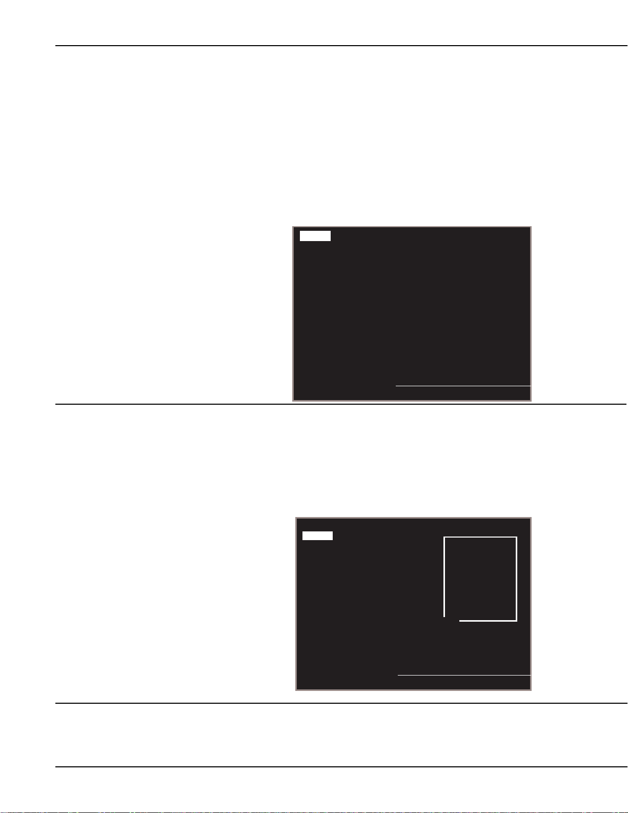
Figure 4-2
Second service screen
Up
Status
Switches
Errors
Hours Run
Cal LV
Man temp al Enable
Pedals
BatLoad Disable
Cal RH
ServO2
Cal Scale
HFS 1153
LFS 887
RH 20
Last Cal: 1/1/00 Fri 3/3/02 9:54am
ADT 22.66
ACT 22.65
P11 327.67
P12 327.67
P21 327.67
P22 327.67
HSP 18208
LV1 117.4
LV2 117.8
LF 60
MC 0.001
TV 1.000
5V 5.059
VR 1.233
DV 0.002
BV 0.000
Status Check status of all self test the software runs continuously. These include: incubator
heater on (INCHTRON), warmer heater on (WRMHTRON), incubator/warmer heater off
(I/WHTROFF), humidifier heater on (RHHTR), remote monitoring data stream
(RS232LOOP), incubator fan on (FANON), and incubator fan off (FANOFF).
If the RS232 option is not installed RS232LOOP will display N/A. To test the circuit if the
option is installed, short pins 2 & 3 on the 9 pin connector on the back of the electrical
enclosure.
Up
Status
Switches
Errors
Hours Run
Cal LV
Man temp al. Enable
Pedals
BatLoad Disable
Cal RH
ServO2
Cal Scale
HFS 1500
LFS 1000
RH 20
INCHTRON PASS
WRMHTRON PASS
I/WHTROFF PASS
RHHTR PASS
RS232LOOP N/A
FANON PASS
FANOFF PASS
TV 1.000
5V 5.059
VR 1.233
DV 0.002
BV 0.000
Figure 4-3
Status menu
Last Cal: 1/1/00 Fri 3/3/00 9:54am
Switches Select to bring up a diagnostic diagram of the unit that displays the status of all the
switches. If the circle next to the switch is lit, the switch is closed; if its not lit, the switch is
open. Also, while the switch status screen is active, you can hold down the alarm silence
button to light the alarm light, system failure light and all LED segments to test them.
4-2 08/27/03 6600-0343-000
Page 29
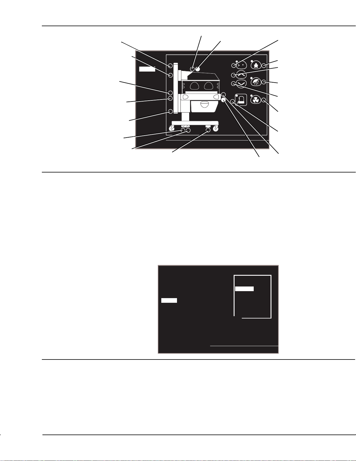
Chapter 4-Troubleshooting
Heater doors open
Canopy up
Heater doors closed
Overide
control
Canopy middle
Canopy hand
switch up
Canopy hand
switch down
Canopy down
Elevating base
pedal down
Elevating base
Figure 4-4
pedal up
Switch diagnostic diagram
Up
Status
Switches
Errors
Hours Run
Cal LV
Man temp al.
Pedals
BatLoad
Cal RH
ServO2
Cal Scale
Canopy pedal
c
37
LastCal: 1/1/02 Fri 3/3/03 10:10am
Humidifier
reservoir engaged
Baby mode
control
Increase
control
Manual mode
control
Decrease
control
Air mode
control
Boost air
curtain control
Humidifier
add water
Errors Lists a chronological log of the last 8 system errors that occurred. Shows error number
and date. It is possible to clear the list.
Hours Run Brings up a screen with 2 hour meters; one that is resetable and one that is not. To reset
the resetable hour meter, highlight CLEAR and push the control knob. The non-resetable
meter will roll to 0 at 199,999.
Cal LV Use to calibrate line voltage at the factory. To calibrate line voltage follow the procedure in
calibration section (chapter 3) of this manual.
Man temp al. Use to enable or disable the patient temperature alarms in the manual mode (revision
1.40 and higher software only). If disabled on the service screen it cannot be enabled on
the user setup screen (wrench icon).The alarm will not activate if a patient set point has
not been entered.
Up
Status
Switches
Errors
Figure 4-5
Hours Run
Cal LV
Man temp al. Enable
Pedals
BatLoad Disable
Cal RH
ServO2
Cal Scale
Last Cal: 1/1/00 Fri 3/3/02 9:54am
Canopy Up Off
Bed Up Off
Bed Down Off
EXIT
HFS 1500
LFS 1000
RH 20
TV 1.000
5V 5.059
VR 1.233
DV 0.002
BV 0.000
Pedal screen
Pedals In the event of an elevating base or canopy pedal switch failure, selecting pedals allows
the canopy to be raised or the bed to be raised or lowered (revision 1.6 software and
higher).
BatLoad Used for manufacturing only, not for service use.
Cal RH Brings up humidifier calibration screen, if servo humidifier is installed. See calibration
section for information on how this screen is used.
Cal Scale Brings up scale calibration screen, if scale is installed. See calibration section for informa-
tion on how this screen is used.
6600-0343-000 08/27/03 4-3
Page 30

Chapter 4- Troubleshooting
A number of diagnostic readings appear on the right side of the service screens.
Figure 4-6
First service screen
Diagnostics
DAC Volt 0.000
Language English
Temp U C
Volume Maximum
Pat Alarm 1.0C
Elevate Enable
Pat Ctrl Both
Pat Algo Cascade
Preheat 25%
Canopy Enabe
Scale U gms
Scale R 10g
Comfort Enable
Set Time
View Mods
Down
HFS 1500
LFS 1000
RH 50
SR 1548
SC 21279
Last Cal: 1/1/02 Fri 3/3/03 9:54am
ADT 22.66
ACT 22.65
P11 327.67
P12 327.67
P21 327.67
P22 327.67
HSP 18208
LV1 117.4
LV2 117.8
LF 60
MC 0.001
TV 1.648
5V 5.059
VR 1.233
DV 0.000
BV 0.000
HFS High fan speed. Should be 1500 +/- 100 (measured at power up only)
LFS Low fan speed. Should be 1000 +/- 100 (measured at power up only)
RH Relative Humidity. % humidity read in the patient chamber
SR Scale counts raw
SC Scale counts corrected
ADT Air display temperature. Temperature read by the first thermistor in the compartment probe.
Should be +/- 0.3ºC of ACT temperature.
ACT Temperature read by second thermistor in the compartment probe. Should be +/- 0.5ºC of
ADT temperature.
P11 Reading from the first thermistor in patient jack 1. Should be +/- 0.5ºC of P12 temperature.
P12 Reading from the second thermistor in patient jack 1. Should be +/- 0.5ºC of P11 temperature.
P21 Reading from the first thermistor in patient jack 2. Should be +/- 0.5ºC of P22 temperature.
P22 Reading from the second thermistor in patient jack 2. Should be +/- 0.5ºC of P21 temperature.
HSP Heat sink probe resistance. Should be 20000 ohms @ 25ºC. see section 4.5 for resistance
verses temperature values.
LV1 Line voltage in first mains circuit. Should be +/- 4V of LV2
LV2 Line voltage in second mains circuit. Should be +/- 4V of LV1
LF 60Hz or 50Hz
MC Motor current. Display number x 7 equals current drawn by the canopy lift or e-base motor
TV Thermistor voltage. Voltage of thermistor circuits located on the mother board.
5V Power supply voltage. Should be +/- 0.25V of 5V
VR Voltage reference. Independent voltage reference. Should be 1.235V +/- 1%
DV DAC output voltage. It should match the DAC volt value within 10 mV.
BV Used for manufacturing only, not for service use.
Across the bottom of the screen the date of last time the temperature and line voltage calibration was performed
appears plus the current time settings of the unit.
4-4 08/27/03 6600-0343-000
Page 31

Chapter 4-Troubleshooting
4.2 Alarm Messages
CAUSE ACTION
FAN FAILURE Fan is missing or not turning. Verify the rubber fan hub is properly seated on the fan
shaft (it may be necessary to wet the part to get it to slide
all the way down on to the shaft). Verify the fan is installed
and turning. During powerup it should spin at low speed
for a few seconds, stop for a second, then start again at
high speed. If the fan is not turning replace the fan motor.
Old design fan. Replace with new design fan. The new fan can be
identified by the grooves molded in the 2 black areas on
the bottom of the fan (side facing the heat sink). The old
fan has smooth surfaced black areas.
Defective optical sensor. If the fan is turning replace the optical sensor.
Defective relay board. If the problem persists replace the relay board.
FAN ALWAYS The heat sink temperature Check heat sink temperature sensor thermistor. See tips.
IN HIGH SPEED sensor thermistor is defective.
Defective control board. If the thermistor is OK replace the control board.
AIR PROBE Probe thermistors show If problem persists intermittently, replace with version
Failure difference > 0.5C (0.3C 1.50 software or higher.
before Rev 1.50 software)
The air sensor is defective. Check ACT and ADT on service screen.
One of the thermistors is Check the air sensor. See tips.
open or shorted.
Defective control board. If the sensor is OK replace the control board.
IN TRANSITION - As the canopy reaches the Check that both heater doors are opening. If the doors
HEAT OFF top position either the canopy are opening check the heater door open switches
up switch or one of the heater See tips. Adjust/replace door tube in rail so doors
door open switches is not open all the way.
closing
As the canopy reaches the Check that the canopy seals are resting on the panels.
bottom position the canopy Realign the canopy following the procedure in the
down switch is not closing. repair section. Test the canopy down switch. See tips.
BAD MEMBRANE Alarm Silence has been on Verify switches. See tips.
SWITCH for more than 20 seconds or If these switches are OK replace the graphics driver
one of the temp control board.
switches has been on for
more than 50 seconds.
POWER FAILURE The 5 volt signal is not Check that power is coming into the unit. Check the
(LED indicator) present. power supplies. See tips.
6600-0343-000 08/27/03 4-5
Page 32

Chapter 4- Troubleshooting
CAUSE ACTION
RADIANT HEATER The radiant heater is Check the radiant heater. See tips.
FAILURE unable to turn on.
(This alarm only
comes on when the Defective radiant heater. Check cable pins 37, 38, 39, and 40 for continuity.
canopy is at the Defective cable between
top position). the relay and control board.
Defective warmer solid Replace the warmer solid state relay.
state relay.
Defective relay board. Replace the relay board.
BED HEATER The bed Tstat is open If the unit was shut off when the heater was hot, allow the
FAILURE (possibly because the unit fan to run for several minutes to cool to below 40 then
was shut down when the power down and back up. If the failure still persists
heater was hot) or the heater check the t-stat and heater resistance. See tips.
or t-stat is defective.
Defective cable between Check cable pins 37, 38, 39, and 40 for continuity.
the relay and control board.
Defective incubator solid Replace the incubator solid state relay.
state relay.
Defective relay board. Replace relay board.
HUMIDIFIER Relay timing problems If this alarm occurs intermittently check software revision.
FAILURE If revision is lower than 1.42 replace with latest revision.
Humidifier heater will not Wait for the heater to cool. Check safety T-stat and
turn on, because safety T-stat heater resistance. See tips.
is open or heater is defective.
Open fuse Check fuses on relay board or interface board.
Defective relay board Replace relay board.
HEATER DOORS The heater door closed Check to be sure both heater doors are closing. If the
NOT CLOSED switches are not closing. doors are closing check the heater door closed
(The canopy lowers switches. See tips.
about halfway then
goes back to the
highest position)
CANOPY PEDAL One of the canopy pedal Check the switches on service screen. See tips.
FAILURE switch is shorted.
Both the footswitch and hand Shut off the unit and power back up to reset. If the pedal
switches are pressed at the is pressed during power up, the footswitch failure messame time (Software 1.4 or sage will appear. Restart to reset.
lower).
BED UP/DOWN One of the elevating base up Check the switches. See tips.
PEDAL FAILURE switches is shorted.
One of the pedals were Shut off unit and power up again to clear alarm.
touched during power up
(Software 1.4 or lower).
MOTOR DRIVE The elevating base motor or Replace the relay board.
FAILURE the canopy motor was running Humidifier will not operate during this failure.
when not turned on.
4-6 08/27/03 6600-0343-000
Page 33

Chapter 4-Troubleshooting
CAUSE ACTION
BABY PROBE 1 Probe thermistors show Replace patient skin probe.
FAILURE and difference > 0.5C (0.3C before
BABY PROBE 2 Rev 1.60 software)
FAILURE Defective probe Calibrate the control board. If failure persists, check
Uncalibrated control board cable from panel to board and check control board.
Defective cable If problem persists intermittently, replace with version
Defective control board 1.60 software or higher.
HEATER DOORS If doors are actually fully Replace switch
NOT OPENED opened; Defective switch
Defective cable between Replace switch/relay board cable
switch and relay board
Defective relay board Replace relay board
Defective cable between relay Replace relay board/control board cable
board and control board
CANOPY PEDAL Pedals have been disabled on When pedal is released the alarm deactivates
DISABLED nurse setup or service
screen and pedal
is pressed
BED HEIGHT Pedals have been disabled on When pedal is released the alarm deactivates
PEDAL DISABLED nurse setup or service
screen and pedal
is pressed
CANOPY PEDAL Pedal pressed during When pedal is released the alarm deactivates. If alarm
PRESSED or power up silence button is pressed while the pedal is pressed,
UP PEDAL a pedal failure alarm activates and the pedals will be
PRESSED or disabled. Shut down the unit and power up to clear
DOWN PEDAL failure.
PRESSED
BABY MODE Baby mode has been Press alarm silence button to deactivate the alarm
DISABLED disabled on service screen and
baby mode button is pressed
TEMPERATURE Calibration data is lost Replace control board with revision 17 or higher
OUT OF If a rev 17 control board is already installed, calibrate
CALIBRATION according to procedure in section 3
6600-0343-000 08/27/03 4-7
Page 34

Chapter 4- Troubleshooting
4.3 Error Codes
ERROR # MEANING CAUSE(S) ACTION(S)
0 Battery failure Battery cannot hold charge. Turn unit on for at least 10 minutes ignoring all
alarms and errors to charge battery. Turn unit off
for at least 3 seconds then turn it back on. If
the unit powers up, continue to use unit. If not,
disconnect the battery, located in the electrical
enclosure, and power up the unit. If the unit powers
up correctly, the battery is bad and should be
replaced.
Defective scale Bad connection to scale or Disconnect scale.
scale failure
Timing problem Software timing revision If revision 1.20 error occurs during startup in
1.20 control board service mode, replace with current revision
software software (kit 6600-0234-850).
Display driver board Defective control board, If the error occurs occasionally, may be random
not responding. cable, or display driver causes; e.g., static discharge. If failure persists,
Communication board. check or replace the cable between display driver
error between the and control boards. If failure persists, replace the
display driver display driver board. If failure persists, replace the
board and the control board.
control board.
1 No Timer2 The Timer2 circuit of the Replace the control board.
Microprocessor on control
board is defective.
2 Scale harness Scale harness defective. Check connection at board and behind probe
disconnected panel. Replace scale harness.
Timer2 Too Fast There is no line frequency Power cycle the unit. If it shows system failure 8
signal to feed timer0 & see the instruction below for system failure 8. If it
timer1 of the micro on still shows system failure 2, replace the control
control board, or the timer2 board.
of the micro on control
board is defective.
3 During ADC All of the thermistors were Before calibrating make sure J1, J2 and J4 on the
calibration the not unplugged during control board are disconnected. Verify JP1 is
software detected calibration. correctly positioned. Try calibrating again. If the
a channel out of error persists, replace the control board.
range. Defective circuit on control
board.
4 Bad Switches Both canopy up and If the error occurs occasionally, may be random
(Software 1.42 canopy down position causes; e.g., static discharge. If failure persists
or lower) switches are closed, use the SERVICE SCREEN to determine which
or both heater door switches are on. Use an ohmeter to test the
open and heater door switches and cabling. See tips.
close switches are closed.
Defective ribbon cable. If switches are OK, check continuity of
Defective relay board. If failure persists, replace relay board.
Defective control board circuit If switches are OK, replace control board.
4-8 08/27/03 6600-0343-000
positions 7, 8, 14 and 16. Replace cable if bad.
Page 35

Chapter 4-Troubleshooting
ERROR # MEANING CAUSE(S) ACTION(S)
5 The 1.235 volt ADC out of calibration. Recalibrate the ADC.
reference
is out of Defective control board. Replace control board.
the 1.171V -
1.259V range.
6 Bad overtemp ADC out of calibration. If the error occurs occasionally, may be random
DAC circuit on Defective control board. causes; e.g., static discharge. If failure persists,
the control recalibrate the ADC. If failure still persists, replace
board. the control board.
7 1.0 V Thermistor ADC out of calibration. Recalibrate the ADC. If the failure still persists
reference voltage Defective control board. replace control board.
is out of 0.951V-
1.049V range.
8 No Line Defective cable between Measure the signal on the control board between
Frequency the control board and the J9 pin 43, and TP1-6 (Ground). It should be a 120
relay board. or 100 hertz square wave. If the signal is OK
Defective relay board. replace the control board. If no signal check the 50
Defective control board. pin cable, pin 43. If bad replace the cable. If cable
is O.K. replace relay board.
11 The ADC on the The humidifier sensor or Disconnect J1 on the control board. If the error
control board is cable is shorted. persists replace the control board. If it powers up
not operating to Bad control board. OK either the cable or the humidity sensor is bad.
spec. (too slow) Reconnect J1 and disconnect the humidity sensor
at the compartment probe. If the unit now powers
up OK the humidity sensor is bad, or the cable
is bad.
12 Bad Checksum Defective control board Change socketed IC U42 on the control board. If
PROM failure persists, replace control board.
13 Bad SRAM Defective SRAM circuit If the error occurs occasionally, may be random
on control board causes; e.g., static discharge. If failure persists,
replace control board.
14 Bad WDOG Defective control board Replace control board.
Watch Dog
15 Heater Safety Air temperature sensor is If the unit was shut off when the heater was hot,
Relay test failure. above 40C at powerup. allow the fan to run for several minutes to cool to
Unable to turn below 40 then power down and back up.
either heater on.
Air display sensor is Check the air sensor. See tips.
shorted.
Defective relay board If failure persists, replace relay board.
Defective DAC circuit on If failure persists, replace control board.
control board.
If the error occurs during Make sure the J1, J2 and J4 on the control board.
ADC calibration it could are disconnected. Verify JP1 is correctly
be caused by failure to positioned then recalibrate.
unplug the probes
during calibration.
6600-0343-000 08/27/03 4-9
Page 36

Chapter 4- Troubleshooting
ERROR # MEANING CAUSE(S) ACTION(S)
16 Unable to turn off The bed Tstat is open If the unit was shut off when the heater was hot,
incubator heater (possibly because the allow the fan to run for several minutes to cool to
by switching the unit was shut down below 40 then power down and back up. If the
solid state relay when the heater was hot) failure still persists check the t-stat and heater
or unable to turn or the heater or t-stat is resistance. See tips.
on incubator defective.
heater in the Defective cable between Check cable pins 37, 38, 39, and 40 for continuity.
calibration mode the relay and control board.
Defective incubator solid Replace the incubator solid state relay.
state relay.
Defective relay board. Replace relay board.
17 Unable to turn off Defective radiant heater. Check the radiant heater. See tips.
radiant heater by Defective cable between Check cable pins 37, 38, 39, and 40 for continuity.
switching the solid the relay and control board.
state relay or Defective warmer solid Replace the warmer solid state relay.
unable to turn state relay.
the radiant heater Defective relay board. Replace the relay board.
on in calibration
mode.
18 Bad Variables Defective SRAM circuit Replace the control board.
on control board.
19 No Audio Battery failure Turn unit on for at least 10 minutes ignoring all
Frequency alarms and errors to charge battery. Turn unit off
for at least 3 seconds then turn it back on. If
the unit powers up, continue to use unit. If not,
disconnect the battery, located in the electrical
enclosure, and power up the unit. If the unit powers
up correctly, the battery is bad and should be
replaced.
Bad connection to scale or Disconnect scale.
scale failure.
Microprocessor was not Replace control board with revision 17 or higher
appropriately reset
Defective audio circuit on Replace socketed IC U22 on control board.
control board. If failure persists, replace the control board.
20 Display WDOG Display driver board If the error occurs occasionally, may be random
Time Out software upset. causes; e.g., static discharge. If failure persists,
replace display board.
22 During operation See other errors. Power down the unit. During the system tests after
neither the radiant power-up the unit should detect system failure 15,
heater or the or Radiant heater failure or bed heater failure.
incubator heater Follow the tips for those failures.
will turn ON Note: If the unit has 1.42 software, replace with
higher revision software.
Distorted line signal If the relay board is revision 9 or lower (see
Chapter 6 for location of rev level code), replace
with revision 10 or higher relay board.
23 Relay board trip Heater duty cycle problem Replace U42 on control PCB with 1.61 software or
point too low higher.
Relay board revision level If Relay board is revision 6 or 7 (to locate board
6 or 7 assembly revision label, see Relay board layout
in chapter 6) replace board.
4-10 08/27/03 6600-0343-000
Page 37

Chapter 4-Troubleshooting
ERROR # MEANING CAUSE(S) ACTION(S)
23 During operation Defective solid state relay. Enter the service mode by holding the override
(CONT.) the system was switch while powering up. In the service mode the
unable to turn safety relay does not drop out so one of the
OFF either the heaters will be on all the time.
radiant heater or Determine which is on and replace the
the incubator corresponding SSR.
heater
24 Bad Air Bad air sensor. This failure is normally caused by a faulty air
Temperature Bad control board. temperature sensor. When the error occurs,
Sensor. The observe the difference between the air control and
system detected air display thermistor readings on the service
a difference in screen. If the difference exceeds 0.3°C, replace
the two air the air temperature sensor and repeat the test. If
thermistors of the error persists, replace the control board.
>0.5 degrees C.
25 Bad Air Flow Fan is missing or not Verify the fan is installed and turning. During
turning. powerup it should spin at low speed for a few
seconds, stop for a second, then start again at
high speed. If the fan is not turning replace the fan
motor.
Old design fan. Replace with new design fan. The new fan can be
identified by the grooves molded in the 2 black
areas on the bottom of the fan (side facing the heat
sink). The old fan has smooth surfaced black areas.
Defective optical sensor. If the fan is turning replace the optical sensor.
Defective relay board. If the problem persists replace the relay board.
26 During the power Defective relay board. Replace the relay board.
up tests the system
was unable to turn
off the RH safety
relay.
27 Bad non-volatile Defective circuit on Replace the control board.
memory control board.
28 The display driver Defective cable Verify the cable between control board J8 and
board lost display driver board is installed properly and is pin
communication to pin connected.
with control board Defective control board. Replace control board.
29 Bad 5VAN signal Defective cable, control Check the system power supplies.
on control board. board, power supply, or See tips.
relay board.
30 Line voltage High or low line voltage. Use the service screen to check if LV1 is with in
reading LV1 is The unit software alarms no alarm range of the unit. If it is, measure the
outside of the if LV is outside the actual line voltage at the power socket, it
expected range the following ranges: must be within the following ranges:
100V: 80 - 115V 100 volt range 90-110 volts
115V: 95 - 132V 115 volt range 104-132 volts
230V: 195 - 270V 230 volt range 198-264 volts
Line Voltage Comp Circuit Calibrate the unit.
is not calibrated correctly.
6600-0343-000 08/27/03 4-11
Page 38

Chapter 4- Troubleshooting
ERROR # MEANING CAUSE(S) ACTION(S)
30 Defective relay board. If the failure persists, measure the voltages at the
(cont.) relay board, measure J37 pin 48 to J37 pin 45 and
J37 pin 49 to J37 pin 45. Line voltage 100/115 = 3-5
volts, difference within 0.4 volts. Line voltage 230 =
7-10 volts, difference within 0.8 If not replace the
relay board.
Defective cable. If the failure persists measure the same voltages at
the control board, J9 pin 48 to J9 pin 45 and J9 pin
49 to J9 pin 45. If the voltages are bad the cable is
bad.
Defective control board. If the voltages are OK replace the control board.
33 Bad RH Solid Defective RH Solid State Replace relay board
State Relay Relay
34 Software revision The software revision of This error may occur after replacing the control
level does not the control board and the or display board. Check Software revision on
match display board does not power up. Replace the software EPROM
match
35 Wrong dipswitch Check the 8 position dipswitch on the control board.
set up Verify that Switch 1 and Switch 2 is on.
36 LV1 differs Line Voltage Comp Circuit Calibrate the unit
from LV2 by is not calibrated correctly
>10% of LV2
Defective relay board. If the failure persists, measure the voltages at the
relay board, measure J37 pin 48 to J37 pin 45 and
J37 pin 49 to J37 pin 45. Line voltage 100/115 = 3-5
volts, difference within 0.4 volts. Line voltage 230 =
7-10 volts, difference within 0.8 If not replace the
relay board.
Defective cable. If the failure persists measure the same voltages at
the control board, J9 pin 48 to J9 pin 45 and J9 pin
49 to J9 pin 45. If the voltages are bad the cable is
bad.
Defective control board. If the voltages are OK replace the control board.
37 Bad Switches Both canopy up and If the error occurs occasionally, may be random
(software 1.60 or canopy down position causes; e.g., static discharge. If failure persists
higher) switches are closed. use the SERVICE SCREEN to determine which
switches are on. Use an ohmeter to test the
switches and cabling. See tips.
38 Bad Switches Both heater door open and If the error occurs occasionally, may be random
(software 1.60 or heater door close switches causes; e.g., static discharge. If failure persists
higher) are closed. use the SERVICE SCREEN to determine which
switches are on. Use an ohmeter to test the
switches and cabling. See tips.
50 Display Bad Defective PROM on the Replace socketed IC U5 on display driver board.
Checksum display driver board If failure persists, replace display driver board.
4-12 08/27/03 6600-0343-000
Page 39

Chapter 4-Troubleshooting
ERROR # MEANING CAUSE(S) ACTION(S)
51 Display Bad Defective SRAM circuit If the error occurs occasionally, may be random
SRAM on the display driver board causes; e.g., static discharge. If failure persists,
replace display driver board.
52 Display No Defective display driver If the error occurs occasionally, may be random
Timer2 board micro circuit. causes; e.g., static discharge. If failure persists,
replace display driver board.
53 Display Timer2 Defective display driver Replace the display driver board.
Too Fast board micro circuit.
55 Display board Defective display driver If the error occurs occasionally, may be random
On Line Self board SRAM circuit. causes; e.g., static discharge. If failure persists,
Test Failure replace display driver board.
60 Line Circuit Failure in relay board Replace relay board.
Failure LV2 calibration circuitry
during calibration
98 Overflow Software upset. If the error occurs occasionally, may be random
causes; e.g., static discharge. If failure persists
replace the control board.
99 Logic problem on Software upset Replace the control board.
the control board.
4.4 Troubleshooting Table
SYMPTOM POSSIBLE CAUSE ACTION
No audio alarm. Defective speaker. Use an ohmmeter to verify the speaker resistance is
about 8 ohms. (J40, pins 5-6)
Audio driver circuitry Replace the control board.
is defective.
Unit equipped with Unit is functioning as a If the sensor is not installed the unit is operating
servo-humidity but manual humidifier. Look correctly. No action required.
unable to set RH at the air sensor and
setpoint above 10 verify the humidity sensor
and % indicator is is installed.
not displayed. Defective humidity sensor. Replace the humidity sensor.
Defective control board. If problem persists, replace control board
ADD WATER Humidifier reservoir switch Remove reservoir, but take care because surface may
message stays on is jammed. be hot! Check that the white button on the reservoir
even after water has switch moves freely. Listen for switch to click when the
been added button is depressed. If problem persists, replace reset
button (6600-1298-500).
Defective ribbon cable. Check continuity of positions 4 and 6. If bad,
replace cable.
Defective relay board. Replace relay board.
Defective control board. Replace control board.
Elevating base will Pedals disabled on Setup Check Setup screen (wrench symbol) or service screen
not go up or down screen or service screen to see if pedals are disabled.
6600-0343-000 08/27/03 4-13
Page 40

Chapter 4- Troubleshooting
SYMPTOM POSSIBLE CAUSE ACTION
Elevating base will Open fuse in the Remove the configeration plug (primary windings).
not go up or down toroidal transformer. Measure the resistance between yellow and blue and
(cont) between orange and brown. They should be less than
10 ohms. If one of these is open, replace the
transformer.
Defective switch. Check switches. See tips.
Defective e-base motor. Check voltage to the e-base. See tips. If OK replace
the e-base motor.
Defective relay board. If bad check the input signals on the relay board. See
tips. If OK replace the relay board.
Defective cable. If bad check the output signals from the control board.
If OK then the cable is bad.
Defective control board. If signals are incorrect replace the control board.
Canopy will Defective belt or clutch. Check if motor turns. Check belt/clutch
not go up
Defective foot pedal switch. Try the hand switch. If OK then foot pedal is bad.
Defective hand control switch. Try the foot pedal or else the other side hand control
switch. If OK then the switch is bad.
Defective canopy motor. Check the voltage to the canopy motor. See tips. If OK
replace the motor.
Defective relay board. If bad check the input signals on the relay board. See
tips. If OK replace the relay board.
Defective cable. If bad check the output signals from the control board.
If OK then the cable is bad.
Defective control board. If signals are incorrect replace the control board.
Canopy will not Defective belt or clutch. Check if motor turns. Check belt/clutch
go down. Defective hand control switch. Try the hand switch on the other side. If OK then the
switch is bad.
Defective canopy motor. Check the voltage to the canopy motor. See tips. If OK
replace the motor.
Defective relay board. If bad check the input signals on the relay board.
See tips. If OK replace the relay board.
Defective cable. If bad check the output signals from the control board.
If OK then the cable is bad.
Defective control board. If signals are incorrect replace the control board.
Canopy travels An object fell into the Check that the floppy door, located behind the radiant
down part way opening behind the heater moves freely. Look to be sure nothing has
then stops or radiant heater floppy fallen behind the door.
goes very slow door.
for the last part
Unit will not switch A patient probe is plugged Disconnect probe from Jack 2 (unit will only allow Baby
to Baby Control into Jack 2 on the probe Control operation with a single probe in Jack 1)
Mode panel
Baby Control is disabled Select BOTH for Patient Control on service screen to
on Service screen activate Baby Control.
Unit will not Defective scale Disconnect scale. If unit powers up, scale is defective.
power up,
alarm sounds Defective battery Remove the electrical enclosure cover and disconnect
the battery. Power down and power up aqain. If the unit
powers up, replace the 9V battery (6600-1024-600).
Defective power supply Check voltages on power supply. See tips.
Microprocessor was not Replace control board with revision 17 or higher
appropriately reset
4-14 08/27/03 6600-0343-000
Page 41

Chapter 4-Troubleshooting
SYMPTOM POSSIBLE CAUSE ACTION
Baby Hot or Baby MANUAL TEMP alarm is Select OFF for MANUAL TEMP alarm on Setup screen.
Cold alarms selected on the Setup
activated while unit screen
is in Manual Mode
Air Temp >38C Alarm is not designed to Push the alarm silence button to clear the alarm.
or Air Temp >40C automatically reset after
alarm activated alarm condition is resolved.
and heater is not
operating even
though compartment
temp is < alarm
Bed will not reach One of the bed heater Feel the heat sink to see if one side is cooler than the
set temp but there cartridges is defective other. Use care, since the heat sink can reach
is no alarm temperatures as great as 121C (250F). Replace the
cartridge on the cool side.
Unit always in Bad dipswitch setting Check position 8 on the control board dipswitch. Should
service screen mode be set to Off position.
Overide switch (>37C) on Check switch on switch diagnostic screen
control panel shorted
Screen refreshes Unbiased RS485 bus Replace control board with revision 17 or higher
every few seconds during idle state
while scale is
attached Defective scale Repair scale
Noise from speaker Microprocessor does not If noise is excessive, replace control board with revision
on power down hold reset during power off 17 or higher
Higher level Fan in high speed for 90 min. To check fan speed, power up unit, hold down the Air
of fan noise after power up. curtain button and press the Down button to force the
(approx. 55db), Fan in high speed for 45 min. unit into low fan speed.
but no FAN after transition from open to
ALWAYS IN closed bed mode.
HIGH SPEED Fan in high speed for minimum
message of 20 min.when bed heater
heatsink is too hot.
Air curtain button pushed.
Bed will not lock in Tilt ball not engaged in finger Tilt the head of the bed platform all the way down while
tilt position pocket latch holding the latch open, then let the latch close to capture
the tilt ball (see Disassembly for complete cleaning in
the O&M manual)
Tilt brake failure Repair brake according to Bed tilt brake shoe replace-
ment in the Repair Procedures chapter of this manual
Baby Cold or Baby Manual Temp. Alarm is Enable Man. Temp. alrm. Refer to description on
Hot Alarm does not disabled on Service Screen pages 4-1 and 4-2.
trigger at 0.5C
eventhough Patient
Alarm is set at 1.0C
6600-0343-000 08/27/03 4-15
Page 42

Chapter 4- Troubleshooting
4.5 Additional Troubleshooting Tips
Following are tips on taking many of the measurements and diagnosing the failures that are referred to in the
troubleshooting charts. For some tips it may be necessary to determine the revision level of the relay board. The
revision code is located in a triangle printed on the component side of the PCB. See figures 6-39 and 6-40.
RAISING AND LOWERING THE CANOPY
In the event of an OmniBed failure, it may be possible to raise or lower the canopy in the service mode. Hold
down the override button (>37) to bring up the service screen; the pedals are now activated to assist in troubleshooting or transport.
INCUBATOR AIR HEATER AND THERMOSTAT
There are two separate incubator heaters. They are connected in parallel for 115 volt operation and in series for
230 volt operation. If the unit has been updated with the bed heater ISO harness the heaters are connected in
parallel for 230 operation also. Measure between the black wire on the incubator SSR and J49 pin 2 on the relay
boards revision 9 or lower or J54 pin 4 on revision 10 and higher..
The resistance of each heater is about 48 ohms so it should measure about 24 ohms for 115 units, 96 ohms for
230 units. The heater and tstat are in series so if the reading is open circuit you must determine which is
defective.
RADIANT WARMER HEATER
Measure between the brown wire on the warmer SSR and the white wire on the output of the isolation transformer. Resistance is about 24 ohms.
POWER SUPPLIES
The 5V and 12V supplies are generated on the power supply. Measure the power supply output at the input to
the relay board.
Signal Location Value
+5V J41 pins 1-4 4.75 to 5.25
+12V J41 pins 7-4 10.8 to 13.2
+5STBY is generated on the relay board. The output of the relay board can be measured on the power supply
bus cable coming off J42 on the relay board.
Signal Location Value
+5V J42 pins 2-1 4.75 to 5.25
+5VSTBY J42 pins 4-1 4.75 to 5.25
+12V J42 pins 3-1 10.8 To 13.2
+5VAN and -5VAN are generated on the control board and can be measured on the test points on the control
board.
Signal Location Value
+5V TP2 pins 1-4 4.75 to 5.25
+5VSTBY TP2 pins 3-4 4.75 to 5.25
+5AN TP1 pins 5-6 4.75 To 5.25
-5AN TP1 pins 4-6 -4.0 To 5.5
SWITCHES/TSTAT
Use switch status diagram on the second service screen to assist in troubleshooting the switches.
Canopy up detect Relay bd J36 pins 1-2 Closed when canopy is up
Canopy down detect Relay bd J36 pins 7-8 Closed when canopy is down
Canopy middle Relay bd J36 pins 4-5 Closed momentarily during transition
Heater doors open Relay bd J31 pins 2-3 Closed when both heater doors are open
Heater doors closed Relay bd J31 pins 1-3 Closed when both heater doors are closed
Humidity reservoir Relay bd J32 pins 2-3 Closed when reservoir is closed
Add water t-stat Relay bd J32 pins 1-3 Opens when reservoir needs water
The following switches are membrane switches. When closed the resistance should be less than 200 ohms.
DISPLAY TOUCH PANEL SWITCHES
Alarm Silence Graphics Driver bd J21 pins1-2 Closed when switch is pressed
>37 degrees Graphics Driver bd J21 pins1-3 Closed when switch is pressed
Servo Control Graphics Driver bd J21 pins1-4 Closed when switch is pressed
4-16 08/27/03 6600-0343-000
Page 43

Chapter 4-Troubleshooting
Up Graphics Driver bd J21 pins1-5 Closed when switch is pressed
Down Graphics Driver bd J21 pins1-6 Closed when switch is pressed
Manual Mode Rad. Htr Graphics Driver bd J21 pins1-7 Closed when switch is pressed
Intervention Graphics Driver bd J21 pins1-8 Closed when switch is pressed
Manual Mode Inc. Graphics Driver bd J21 pins1-9 Closed when switch is pressed
Canopy foot control
Left or Right Relay bd J40 pins 3-4 Closed when either switch is pressed
Canopy hand control
Left up Relay bd J35 pins 2-4 Closed when switch is pressed
Left down Relay bd J35 pins 3-4 Closed when switch is pressed
Right up Relay bd J35 pins 6-5 Closed when switch is pressed
Right down Relay bd J35 pins 7-5 Closed when switch is pressed
E-base
Left or right up Relay bd J40 pins 2-4 Closed when either switch is pressed
Left or right down Relay bd J40 pins 1-4 Closed when either switch is pressed
HUMIDIFIER HEATER/SAFETY T-STAT
The humidifier has two separate heaters that are connected in parallel for 115 volt operation and in series for
230 volt operation. The safety t-stat is in series with the heater. Measure at J53.1 to J53.3
The resistance of each heater is about 144 ohms so it should measure about 72 ohms for 115 units, 288
ohms for 230 units.
AIR PROBE and PATIENT PROBE
There are two thermistors in each air probe or patient probe. During stable temperature conditions the thermistors should read the same resistance within a few ohms.
Patient probe #1 Control bd J4 pins 1-3, 2-3
Patient probe #2 Control bd J2 pins 1-3, 2-3
Air probe Control bd J1 pins 1-2, 3-4
Temperature (C) Resistance (Ohms)
20 12527
25 10000
30 8037
35 6500
INCUBATOR HEAT SINK TEMPERATURE SENSOR THERMISTOR
Thermistor Control bd J3 pins 1-2
Temperature (C) Resistance (Ohms)
20 25000
25 20000
30 16102
35 13048
40 10636
80 2506
90 1827
100 1353
110 1017
120 775
6600-0343-000 08/27/03 4-17
Page 44

Chapter 4- Troubleshooting
E-BASE MOTOR and CANOPY MOTOR
If you must replace a footswitch when the bed is all the way down, disconnect the shorted footswitch, then
short switch pins on the relay board. On units with 1.60 software or higher, use pedal screen on service screen
to raise or lower the bed.
To troubleshoot the canopy clutch and roll pins, run the ebase all the way up. Take the bottom end cap off the
rail and the back panel off the electrical enclosure. Use a flash light to look up into the rail and see what moves
when the canopy slips. If the motor coupler (item 12 page 6-32) is not turning, then replace the gear box
assembly, 6600-0217-850. If the motor coupler is turning, then either the slip clutch or one of the roll pins is
missing or defective. If the clutch turns and not the sprocket then the problem is a defective slip clutch. If
neither turns, the problem is probably a sheared roll pin.
The e-base motor and canopy motors are driven by the same circuits. The e-base is always driven at 24 volts
DC (acceptable range 24-32), and the canopy motor is driven at 24 volts (acceptable range 24-32)when going
up and 12 volts (acceptable range 12-16) when going down. The following chart shows the control signal
values and the output voltages for each of the motor conditions.
Switch Control Signals, Relay Board E-base Canopy
Raise canopy 0 0 1 1 NA NA +24V Gnd
Lower canopy 1 0 0 1 NA NA Gnd +12V
Raise E-base 0 0 1 0 +24V Gnd NA NA
Lower E-base 0 0 0 0 Gnd +24V NA NA
None NA 1 NA NA NA NA NA NA
J37 pin 23 J37 pin 26 J37 pin 24 J37 pin 27
24V SELECT E/H ACTIVATE NVERTPOLARITY E/H SELECT J45-1 J45-2 J46-1 J46-3
4-18 08/27/03 6600-0343-000
Page 45

Chapter 4-Troubleshooting
4.6 Servo Controlled Oxygen
Servo Controlled Oxygen Service Screen
To access the service screens, hold in the override button (>37) during power up until the software revision
screen appears. Release the button and the first service screen will appear. Select DOWN on the first screen
to go to the second service screen. Select Servo O2 to bring up the Servo Controlled Oxygen service screen.
Up
Status
Switches
Errors
Hours Run
Cal LV
V1: CLOSE oxygen0: 52
V2: CLOSE oxygen1: 52
VC: CLOSE sensor0: 109.3
K1: CLOSE sensor1: 109.4
Cal 02 temp: 39.3
EXIT humidity: 7
Man temp al. Enable
No Humidifier
ServO2
No Scale
HFS 1511
LFS 1016
RH 0
MC 0.001
TV 1.000
5V 4.978
VR 1.238
DV 0.000
Figure 4-7
Servo O2 service screen
V1 Select to open or close supply valve one in the valve housing located beneath the electrical
enclosure.
V2 Select to open or close supply valve two in the valve housing located beneath the electrical
enclosure.
Last Cal: 1/1/00 Fri 3/3/00 9:54am
VC Select to open or close calibration valve in the sensor housing located beneath the bed. Open
is calibration position and closed is the normal operation position. The calibration fan is on and
the cooling fan is off when VC is open.
Note: The cooling fan is on whenever the Servo Controlled Oxygen service screen is selected
and VC is closed.
K1 Select to open or close the relay on Relay PCB that powers the valves.
Cal 02 Initiates calibration routine.
oxygen0 Oxygen reading in percent from first sensor cell (23 - 280 mv = 21 - 100% O2).
oxygen1 Oxygen reading in percent from second sensor cell (23 - 280 mv = 21 - 100% O2).
sensor0 Voltage output in millivolts from first sensor cell.
sensor1 Voltage output in millivolts from second sensor cell.
temp Temperature in degrees Celsius read from a sensor inside the sensor housing located be-
neath the bed. See R/T curve in Tips
humidity Relative humidity in percent read from a sensor inside the sensor housing located beneath the
bed.
6600-0343-000 08/27/03 4-19
Page 46

Chapter 4- Troubleshooting
Servo Controlled Oxygen Alarm Messages
Alarm Message Meaning Cause Action
Low Oxygen Sensor1 reading is Low O2 supply pressure or flow. Be sure supply is greater than 45psi (310 kPa)
> 3% below the and flow rate is greater than 45 lpm. If flow rate is
oxygen set point 7 Inlet screen occluded. <45 check that the inlet screen in the regulator is
minutes after a set not occluded. Clean or replace screen.
point change or the
Omnibed canopy Air leaks into infant Be sure all doors and portholes are closed
was closed. compartment.
Supply Valve not opening Check supply valves, see tips. If valves OK,
check entire O2 supply circuit for leak.
Endcap safety valve not Check valve and spring assembly, see tips.
opening
Calibration valve is not closing Check the calibration valve. See tips.
Infant compartment vents Check to be sure that the two vents in the infant
occluded compartment under the bed are not occluded.
High Oxygen Sensor1 reading Oxygen set point recently Allow time for oxygen level to drop.
more than 3% lowered
above set point Supply valve(s) not closing Check supply valves and kinked hoses, see tips
Oxygen Probe One of the sensors is Defective Sensor(s) In service mode sensor0 and sensor1 should be
Failure reading out of range 23-280. If outside this range replace the
(23-280 millivolts on sensors. If in range ensure oxygen0 and oxygen1
units with 1.3 read within 3% of each other or replace the
software or higher) sensors.
or the difference Leak or occlusion in sensor Be sure sensor housing is seated properly and
between the two O2 housing area. the retaining screws are tight. Be sure sensor
sensors is above 3%. gaskets are in place and the tubing is seated
correctly in the connectors.
Check to be sure that the two vents in the infant
compartment under the bed are not occluded.
Defective cable or connection Measure the voltage at J85.8-J85.7(sensor0) and
J85.6-J85.7(sensor1) and compare them to
displayed sensor0 and sensor1.
If the measurement is the same as the displayed,
check the cable and sensor contacts
Defective Servo O2 board If the measurement is not the same as the
displayed, replace the Servo O2 board
O2 Cal Lost- Servo oxygen unit Perform oxygen calibration. Run calibration.
No O2 has never been
calibrated. Unit
will not operate until
initial calibration is
performed.
Cell voltage less Earlier software versions did Replace display software with 1.62 or higher
than 33 mv not store voltages this low
Oxygen System The sensor plug Unit is cold <15 degrees C Allow unit to warm up.
Failure 1 thermistor temperature
reading is out of the Cooling fan is not running Test the cooling fan. See tips.
range: 15C-55C. when the sensor housing Disconnect the cable and measure the resis-
temperature gets above tance of the thermistor between J85.4&J85.5.
50 degrees. See R/T chart in tips. If sensor is shorted, open,
or values dont agree with the R/T chart replace
Defective sensor plug the sensor plug assembly or the cable.
thermistor or cable.
Defective servo O2 board If resistance is in range replace the servo O2 board.
4-20 08/27/03 6600-0343-000
Page 47

Chapter 4-Troubleshooting
Alarm Message Meaning Cause Action
Oxygen System The RH reading is Defective sensor plug. Measure the humidity sensor voltage between
Failure 2 out of valid range: J85.2 & J85.1. If the voltage is outside the range of
1-99. When out of 0.7V- 4.0V, replace the sensor plug assembly.
range it displays 0
in service mode. Defective servo O2 board If it is in the correct range replace the servo O2
Board
Oxygen System The checksum test Defective Microcontroller Replace microcontroller U6 on the Servo O2 board
Failure 3 performed during
power up testing failed.
Oxygen System Analog to digital Defective Servo O2 board Replace servo O2 board
Failure 4 converter circuit self
test failed. The
reading of Vtest is
out of the valid
range:1.216V-1.254V
Check O2 After calibration, both O2 supply is not connected Verify O2 supply, minimum 45psi and 45lpm
supply supply valves are is connected to the inlet.
opened and and after
approx. 20 seconds Kinked hose in sensor Check hoses.
sensor1 reading is not housing
greater than 23%.
Oxygen System Check O2 Supply O2 supply is not connected Verify O2 supply, minimum 45psi (310 kPa) and
Failure 5 alarm has been 45 lpm is connected to the inlet.
silenced twice and Calibration valve stuck in Check the calibration valve, see tips.
the sensor1 reading calibration position.
is still not greater
than 23%. Supply valves not opening Check supply valves, see tips.
Leak or occlusion in sensor Be sure sensor housing is seated properly and
housing area. the retaining screws are tight. Be sure sensor
gaskets are in place and the tubing is seated
correctly in the connectors. Check to be sure
that the two vents in the infant compartment
under the bed are not occluded.
Oxygen System The Giraffe control Defective Servo O2 board Replace servo O2 board
Failure 6 board can not
communicate with Defective Cable Check that the cable between the Giraffe control
Servo O2 board board and the Servo O2 board is seated properly.
Oxygen System Power up test detected Defective Servo O2 board Replace Servo O2
Failure 7 a problem with the board
watchdog circuit.
Calibration In calibration mode Calibration valve is not Check the calibration valve and fan. See tips.
failed. after 5 minutes both opening or the calibration fan
sensors are not is not turning on.
reading between 23
and 55 millivolts so the Bad sensors Replace the sensors
unit cant calibrate.
FiO2>26% Elevated oxygen Auxiliary source of oxygen Check for secondary sources, such as ventilator
levels in patient supply in patient compartment or resuscitation bag.
compartment not
controlled by the Leak in the servoO2 system Check supply valves. See tips.
servoO2 system. supply valve
6600-0343-000 08/27/03 4-21
Page 48

Chapter 4- Troubleshooting
Use Static Control Work Station to help ensure static charges are safely conducted to ground.
The velostat material is conductive; do not place electrically powered boards on it. Whenever
this symbol appears beside a procedure, take static control precautions.
Servo Controlled Oxygen Toubleshooting Tips
Check Supply valves and Endcap Safety Valve
Power up unit in service mode. Close the canopy. Select Servo O2 on second page. Be sure O2 is connected.
Open V1. You should hear gas flow. Close V1, open V2, you should hear gas flow. Close V2, gas flow should
stop. If supply valves are open and there is no gas flow, check that the endcap safety valve located in the
bottom of the rail is not stuck in the closed position. Check that the two way valve is not occluded or the the
spring assemly has not failed.
If both valves are not opening, test the fuses and supply valves. Disconnect J83 at the Servo O2 board. Measure the resistance on harness pin 1 to pin 2. It should be the supply valve resistance (50 to 100 ohms). If not,
the fuse is opened or the supply valve is defective. Repeat for the second supply valve with pins 3 to 4.
If the valves check OK, the Servo O2 board is defective.
Note: With one supply valve open the flow rate should me be a minimum of 35 lpm. With both supply valves
open, the minimum flow rate should be 40 lpm. If the flowrate is low, check that the regulator inlet screen is not
occluded.
Check calibration valve/Calibration fan
The calibration valve is located beneath the chassis in the sensor housing. The calibration fan is mounted in the
sensor housing next to the calibration valve. Power up unit in service mode. Select Servo O2 on second page.
Open VC. This should open the calibrate valve and turn on the calibration fan. Verify the calibration fan is
running. If the fan is running then the Servo O2 board is OK and the calibration valve may be defective. If the
fan is not running check the control signal from the Servo O2 board to verify voltage is present when VC is
opened to determine if the fan or board is defective.
Check cooling fan
The cooling fan is mounted to the sensor housing door on the chassis cover. Power up unit in service mode.
Select Servo O2 on second page. The cooling fan should be running.
If fan is not running verify 10.0 - 13.2 Volts at J86-1 to J86-2. If voltage is present the fan is defective.
If voltage is not present the Servo O2 board is defective. Open VC, you should hear a click and the cooling fan
should stop. If the fan does not stop the Servo O2 board is defective.
Sensor housing temperature sensor temperature to resistance curve
Temperature Resistance
15C 15.720 kohm
25C 10.000 kohm
30C 8.056 kohm
35C 6.530 kohm
40C 5.326 kohm
45C 4.369 kohm
50C 3.604 kohm
60C 2.491 kohm
4-22 08/27/03 6600-0343-000
Page 49

Chapter 5- Repair Procedures
Use Static Control Work Station to help ensure static charges are safely conducted to ground.
The velostat material is conductive; do not place electrically powered boards on it. Whenever this
symbol appears beside a procedure, take static control precautions.
WARNING w After performing any repair or calibration, always perform the Service Checkout Proce-
dure before putting the unit back into service.
5.1 Canopy Removal for Replacement (Figures 5-1, 5-2 and 5-3)
1. Raise the canopy to about 18 inches above the side walls.
2. Using a small straight blade screwdriver, remove the 6 arrow clips that secure the soffit beneath the rear of
the canopy and remove the soffit.
3. Using a 2.5mm hex key, remove the 4 screws that secure the heater housing cover to the heater door
bracket and remove the cover.
4. Lower the canopy until it is about 3 inches above the side walls. Unplug the unit.
5. Using a 7 mm socket or wrench, remove the 4 nuts and lockwashers across the back that secure the canopy
to the heater door bracket (two of the nuts are accessed though the access holes in the canopy bracket).
6. Remove the 2 nuts (7mm wrench) from the setscrews and the 3 screws (3mm hex key) in each side seal
extrusions, then remove the side seals extrusions.
On units with newer seals with the zip locking lip, use a 2.5mm hex key to remove the 4 screws that secure
the corner pins to the 4 corner flanges and remove the corner pins, then remove the 2 front corner flanges.
To access the 3 screws that secure each side seal, use a flat blade screwdriver to pry the outside lip of the
seal open and then zip open
the groove in the seal.
Heater housing cover
Left inside cover
Intermediate
oblong locking hole
Soffit
Housing cover screw
Arrow clip
Figure 5-1
Heater housing cover and soffit
6600-0343-000 08/27/03 5-1
Right inside cover
Canopy
Page 50

Chapter 5- Repair Procedures
Lift the canopy slightly from the front to pivot the back of the canopy away from the heater door bracket
and remove the 2 rear corner flanges. Remove the rear seal.
7. Using 2.5mm hex key, remove the three button head screws across the top of the canopy while holding
the threaded inserts inside the canopy.
8. Remove the canopy.
9. Install 4 label in the canopy cormers in the same place they were on the old conopy. Transfer the remaining parts from the old canopy to the new.
10. Reassemble in reverse order. If alignment is required, see section 5.311 Aligning the Canopy.
5.11 Replacing the Seals (Figure 5-3)
Note: When replacing older seals, that do not have a zip locking lip, order kit 6600-0237-850.
1. Raise the canopy to working level, remove the soffit and heater housing cover.
Canopy Bracket
Housing bracket
Heater Housing
Button head screws
Access holes
Canopy mounting nuts
Heater Door Bracket
Figure 5-2
Canopy, Bracket and Heater housing
Canopy
and threaded inserts
2. Using a 2.5mm hex key, remove the 4 screws that secure the corner pins to the 4 corner flanges and
remove the corner pins. Remove the 2 front corner flanges.
3. Using a 7 mm socket or wrench, remove the 4 nuts and lock washers across the rear of the heater door
bracket that secure the canopy to the bracket (two of the nuts are accessed though the access holes in
the canopy bracket). Lift up the seals to access the hardware, and remove the 4 screws that secure the
front seal then remove the front seal.
4. Remove the nylock nuts (7mm wrench or socket) from the setscrew located on each side of the heater
door bracket. Remove the 2 set screws (2mm Allen wrench) and the 2 spacers from the side seals.
5. Lift the canopy slightly from the front to pivot the back of the canopy away from the heater door bracket
and remove the 2 rear corner flanges. Remove the rear seal.
6. Remove the 3 screws (2.5mm hex key) from each side seal extrusion. Remove the 2, M4 nuts (7mm
socket). Remove the side seals.
5-2 08/27/03 6600-0343-000
Page 51

Chapter 5- Repair Procedures
Front seal
Front seal extrusion
Side seal
Rear seal extrusion
Side seal
Rear seal
Side seal
Figure 5-3
Front seal
Canopy seals and extrusions
7. Remove the 4 screws (3 mm hex key) that secure the front seal to the front seal extrusion, then remove
the front seal.
Replace the seals and reassemble in reverse order. Zip the front and side seals closed. The lip of the
outer part of the seals fits into the groove in the inner part and closes like a plastic sandwich bag.
5.12 Porthole Door Replacement (Figure 6-6)
1. Use a flat edge screwdriver to pry off the hinge cover.
2. Open the door to unload the springs.
3. Slide the hinge pin down, out the hole at the bottom of the hinge.
4. Remove the porthole door.
5. Now the door springs can be accessed along with screws that secure the inside half of the hinge cover.
6. To replace the porthole door, put the door back in place in the open position, install the springs, then slide
the hinge pin back in place.
6600-0343-000 08/27/03 5-3
Page 52

Chapter 5- Repair Procedures
7. Close the door and snap the hinge cover back in place, keeping the thin side of the cover closest to the
porthole.
Screw
Canopy
bracket
Conical cap
Smaller hole
Lift rail
Figure 5-4
Disconnecting heater door cable
Hole plug
Nut
Screw
Door cable
Front cable clip
Steel tube
Side cable clip
Conical cap
Plastic tube
5.2 Canopy Lift Assembly Repair Procedures
5.21 Removing the right upright (motor side) (Figures 5-1, 5-4, 5-5, 5-6, 5-7 and 5-14)
1. Lock the rails in the intermediate position by raising the canopy then slowly lowering it until the rail locking
screws align with the horizontal oblong holes in the rails. Lock both rails by turning the screws CCW (4mm
hex key) until they lock the rails in place. Switch off the unit and disconnect the power cord.
2. Using a small straight blade screwdriver, remove the 6 arrow clips that secure the soffit beneath the rear
of the canopy and remove the soffit.
3. Using a 2.5mm hex key, remove the 4 screws that secure the heater housing cover to the heater door
bracket and remove the cover.
4. Remove the right inside cover by removing the 2 screws and nuts (2mm hex key, 5.5mm wrench) that
secure it around the door cable.
5. Remove the steel tube that routes the door cable into the lift rail. Use a 3mm hex key to remove the screw
in the front cable clip. Use a 2.5 mm hex key and 7 mm wrench to remove the screw and nut in the side
cable clip.
6. Disconnect the heater door cable. The cable end is accessed through the two holes on the back of the lift
rail. First pry off the hole plug, then rotate the plastic tube so the hex head screw securing the conical cap
faces the rear. Push a small hex key or screwdriver through the small lower hole in the rail, through the
lower hole in the plastic tube inside the lift rail, and back through the rail on the other side of the tube to
5-4 08/27/03 6600-0343-000
Page 53

Wire covers
Decorative strip
Chapter 5- Repair Procedures
Upright
Bottom endcap
Figure 5-5
Upright decorative strips, end caps and wire covers
hold the tube in place. Insert a 2 mm hex key through the larger hole to partially back out the screw that
fastens the conical cap to the plastic tube. Pull the cap out of the rail. Pull out the key in the tube hole and
let the tube drop down in the upright.
7. Remove the two flat head screws (3mm hex key) that hold the canopy bracket to the lift rail.
8. Use a 2.5 mm hex key to loosen the 2 screws in the keyhole slots and remove the 6 remaining screws that
secure the controller cover, then remove the cover.
9. Slide the decorative strip up about ½ in the groove on the outside of the upright to access hardware that
secures the lower end cap. You may wish to use a piece of tape to grip the strip. Use a 2.5mm hex key to
remove the screw, then remove the cap (on units equipped with the Servo Oxygen option, see 5.1115
Endcap Saftey Valve near the end of this chapter for instructions on removing the endcap manifold). Slide
the decorative strip down to access the screw that secures the upper end cap and remove the screw and
decorative strip. The upper end cap can now be removed by lifting the center cap up out of the lift rail,
pushing the exhaust door back, then sliding the outside end cap up and past the spring.
Lift Motor
Right upright
Figure 5-6
Removing the lift motor
6600-0343-000 08/27/03 5-5
Motor bracket
Lift Motor Coupler
Gear box
Page 54

Chapter 5- Repair Procedures
Button head screw
Standoff
Lock washer
Back cover
Nut bar
Control knob
Figure 5-7
Display module disassembly
Font bezel
10. Using a 2mm hex key, remove the 4 button head socket screws and lock washers that secure the back
cover to the display module and remove the panel.
11. Remove the control knob from the front of the display by pulling it straight off its shaft.
12. Remove the four standoffs and lock washers (6mm wrench) that held the back cover then remove the
front bezel of the display module.
13. Using a 2mm hex key, remove the screw that secures the wire cover to the side of the upright.
14. To remove the wire cover, slide the wire cover up about ½, and then pull it straight back by grasping its
back edge.
15. Using a 3mm hex key, remove the 2 screws that secure the display module to the nut bar and pull the nut
bar up and out of the upright. Using a 3mm hex key, remove the screw that attaches the ground wire. Be
careful not to drop the star washers down into the rail.
16. First remove the connection panel (2.5mm hex key) at the bottom of the electrical enclosure. Disconnect
the motor leads on the relay board. Remove the two screws (2.5mm or 3mm hex key)that secure the lift
motor/gear box to its mounting plate and remove the motor/gear box.
17. While holding on to the lift rail with one hand, use a 4 mm hex key to tighten (CW) the intermediate stop
set screw until the screw bottoms out and the inner rail is free, then carefully let the lift rail extend to its full
height, releasing spring tension. It may be necessary to pull gently on the canopy to free the standoffs
from the rail.
18. Hold on to the upright, and using a 4mm hex key, remove the 2 screws in the holes in the lower side of the
upright . Remove the entire upright assembly.
5-6 08/27/03 6600-0343-000
Page 55

Chapter 5- Repair Procedures
You can disconnect the electrical connector and ground to completely remove the upright or, if you wish, there
is enough slack in the wiring to allow you to work on the upright on a table or bench close to the unit without
disconnecting the electrical or ground connection. Refer to 5.23 for right rail internal repairs and 5.24 for
reassembling the right upright.
5.22 Removing the left upright (Figures 5-1 and 5-5)
1. Lock the rails in the intermediate position by raising the canopy then slowly lowering it until the rail locking
screws align with the horizontal oblong holes in the rails. Lock both rails by turning the screws CCW (4mm
hex key) until they lock the rails in place. Power down the unit and unplug it from the power outlet.
2. Using a small straight blade screwdriver, remove the 6 arrow clips that secure the soffit beneath the rear of
the canopy (See Fig.5-1) and remove the soffit.
3. Using a 2.5mm hex key, remove the 4 screws and washers that secure the heater housing cover to the
heater door bracket and remove the cover.
4. Remove the left inside cover by removing the 2 screws and nuts (2mm hex key, 5.5mm wrench) that
secure it around the electrical cables.
5. Remove the two flat head screws (3mm hex key) that hold the canopy bracket to the lift rail.
6. Disconnect the two electrical connectors to the heater housing and feed them out of the slot in the canopy
bracket so they do not catch when the rail tension is released.
7. Loosen the 2 screws in the keyhole slots and remove the 6 remaining screws that secure the controller
cover, then remove the cover.
8. Slide the decorative strip up about ½ in the groove on the outside of the upright to access the screw that
secures the lower upright end cap. Use a 2.5mm hex key to remove the screw, then remove the cap. Slide
the decorative strip down to access the screw that secures the upper upright end cap and remove the
screw and decorative strip. The top end cap can now be removed by lifting the center cap up out of the
extrusion then sliding the outside end cap up and past the spring.
9. Using a 2mm hex key, remove the 4 button head socket screws and split ring washers that secure the
back cover to the display module and remove the cover.
10. Remove the control knob from the front of the display by pulling it straight off its shaft.
11. Remove the four standoffs and lock washers (6mm wrench) that held the back cover then remove the
front bezel of the display module.
12. Using a 2mm hex key, remove the screw that secures the wire cover to the inside of the upright.
13. To remove the wire cover, slide the wire cover up about ½, and then pull it straight back by grasping its
back edge.
14. Using a 3mm hex key, remove the 2 screws that secure the display module to the nut bar and pull the nut
bar up and out of the upright. Using a 3mm hex key, remove the screw that attaches the ground wire. Be
careful not to drop the star washers down into the rail.
15. While holding on to the lift rail with one hand, tighten (CW) the intermediate stop set screw until the inner
rail is free, then carefully let the lift rail extend to its full height, releasing spring tension. It may be necessary to pull gently on the canopy to free the standoffs from the rail.
16. Hold on to the upright, and using a 4mm hex key, remove the 2 screws in the holes in the lower side of the
upright . Remove the entire upright assembly.
6600-0343-000 08/27/03 5-7
Page 56

Chapter 5- Repair Procedures
Lift rail
Pinch guard
Access hole
Side roller bracket
Figure 5-8
Buoyancy springs
Rollers
Belt block
Right upright
Belt channel
Motor
bracket
Right upright disassembly
You can disconnect the electrical connector and ground to completely remove the upright or, if you wish, there
is enough slack in the wiring to allow you to work on the upright on a table or bench close to the unit without
disconnecting the electrical or ground connection. Refer to 5.25 for left rail internal repairs and 5.26 for reassembling the left upright.
5.23 Right rail internal repairs
5.231 Removing the inner rail assembly (Figure 5-6 , 5-8 and 5-17)
1. Using a 2.5 mm hex key, remove the 2 screws located at either end of the upright in the rear dovetails that
secure belt channel to the inside of the upright. Using a 3mm hex key, remove the side roller bracket.
Remove the lift motor coupler components if still attached to the rail assembly. Pull the entire rail assembly
up out of the upright.
2. Remove the pinch guard by sliding it up then pulling it off.
3. Remove the nut and washers at the bottom of the belt channel that secure the heater door opening rod to
the bracket and remove the assembly.
5.232 Replacing rollers and tension springs (Figure 5-9)
1. The rollers can be removed one at a time by removing the screw (4mm hex key) at their hub and pulling
off the roller and bearing. When reinstalling, torque the screws to 45 in. lbs (reference).
5-8 08/27/03 6600-0343-000
Page 57

Chapter 5- Repair Procedures
2. To replace the roller tensioning spring, first use needle nose pliers to pull the tension spring off the roll pin
at the end of the lift rail. Then take off the 2 center rollers and slide the tensioning plate out of the lift rail.
Remove the old spring.
3. Reinstall the 2 center rollers. Use a hex key in the center access slot to lift the tensioning plate up so that
you can screw the rollers into the holes in the plate. Torque rollers screws to 45 inch lbs (reference).
4. Using pliers, pull the tensioning spring up onto the roll pin at the end of the rail.
5.233 Replacing the micro-switches
1. Using a 4 mm wrench remove the 2 nuts and washers that secure the lower switches to the rail. Use a
small Phillips head screwdriver to remove the screws that secure the upper switch.
2. Unsolder the 2 electrical connections.
5.234 Separating the lift rail from the belt channel (Figure 5-8)
1. If you can access the screw head through the access hole in the lift rail go to step 2. If you can not access
the screw, push the lift rail and the belt channel together and lift the belt block up past the roll pin so you
can see the screw head through the access hole in the lift rail.
2. Remove the screw that secures the lift rail and the belt channel together (this will require either a 3 or 4mm
hex key).
Roller mounting screw
Bearing
Center rollers
Lift rail
Figure 5-9
Rollers and tensioning spring
6600-0343-000 08/27/03 5-9
Tensioning plate
Roller tensioning spring
Page 58

Chapter 5- Repair Procedures
5.235 Replacing the drive belt (Figure 5-10)
1. Using a 5.5mm wrench, remove the nylock nuts that secure the springs coil to the plastic belt block. The
springs will roll back around their spools.
2. Using a 2mm hex key, remove the 2 screws that secure lower belt guard, remove the guard and run the
belt off the bottom sprocket.
3. Using a 2mm hex key, remove the 4 screws (one in each corner) that hold the halves of the plastic belt
block together.
4. Using a 2mm hex key, remove the 2 screws in the brass belt-tensioning block. Note that one link protrudes
from the brass belt block.
5. Remove and replace the belt.
Plastic belt block
Belt
Figure 5-10
Replacing the drive belt
Leaf spring
Roll pin
Brass belt block
5.236 Replacing the rail buoyancy springs (Figure 5-11)
1. Using a 5.5mm wrench, remove the nylock nuts that secure the spring to the plastic belt block. The
springs will roll back around their spools.
2. The spools slide out of their mounting slots. To reinstall the spools, assemble each of the spools by
wedging them into the rail with the delrin washers at either end of each spool, then slide all the assemble
spools into their mounting slots at the same time. Lubricate the spring spools by placing a drop of
Lubriplate where the spool hub seats in the slot.
Note: Replace all the buoyancy springs in an upright at the same time.
Note: When reassembling the rails, be sure the leaf spring is on top of the micro switch to prevent the
switch from breaking off.
5-10 08/27/03 6600-0343-000
Page 59

Buoyancy springs
Nylock nuts
Chapter 5- Repair Procedures
Delrin washers
Spring spools
Belt channel
Figure 5-11
Replacing the rail buoyancy springs
Belt block
Micro-switch
5.237 Replacing the slip clutch or motor roll pin (Figure 6-16)
1. After removing the right rail, use a punch that is smaller than .090 to drive out the motor pin (item 18 on
page 6-27).
2. To remove the slip clutch (item 4), tap out the axle (item 2 on page 6-27).
5.24 Reassembling the right upright (Figure 5-5, 5-8, 5-14 and 5-17)
1. To reassemble replace the screw that secures the lift rail to the belt channel. If the belt block is not already
hooked on the roll pin, then push the lift rail and belt channel together so that the buoyancy springs uncoil
about 3 inches and the hook on the belt block can ride up over the roll pin in the belt channel.
2. Reinstall the pinch guard. Be sure to orient the pinch guard with the holes in the keyhole slots at the
bottom of the rail.
3. Slide the assembly back into the upright, reinstall the screws that secure it to the belt channel and reinstall
the side roller bracket . To make sure it is properly seated in its tracks, move the rail assembly through its
full range of travel to make sure it does not hang-up or bind before reattaching the upright to the unit.
Reinstall the 2 pieces of the motor coupler that fit on the shaft at the base of the upright that mate with the
coupler piece on the gearbox shaft.
4. To assist in reattaching the upright to the unit, there are four mounting studs on the bracket casting that
mate with four holes in the upright. Place the upright on the studs. Be sure the canopy bracket is in front of
the upright. Be careful not to pinch any wires between the unit and the upright.
5. Secure the upright to the unit by reinstalling the 2 screws in the holes inside the upright. Pull any excess
wiring slack in the upright channels into the electrical enclosure. Be careful not to drop the screws into the
upright.
6. Push the lift rail down into the upright until the rail locking screws align with the horizontal oblong holes in
the rail. Lock the rail by turning the screws CCW (4 mm hex key) until they lock the inner rail in place.
Install the two flat head screws that attach the canopy bracket to the lift rail.
7. Attach ground wire to rail. Fasten the dispaly module to the upright with the two screws and nut bar
removed earlier.
6600-0343-000 08/27/03 5-11
Page 60

Chapter 5- Repair Procedures
8. Reinstall the wire cover. Take care to route the wires in the upright channels and not to pinch them with the
cover when securing with the screw.
9. Reinstall the front bezel of the display module and secure with the 4 standoffs and lock washers. Push the
control knob back onto its shaft.
10. Fasten the back panel to the display module with its 4 mounting screws.
Side roller bracket
Lift rail
Cable carrier
Left upright
Figure 5-12
Left inner rail
Cable carrier channel
11. Fish a wire or string down through the lift rail and hook it to the upper hole in the tube on the door opening
assembly, then pull the tube up from the bottom of the lift rail until the lower hole in the tube lines up with
the small hole in the back of the lift rail (you may need to raise the bed height to fit the tube under the
upright). Push a hex key through the smaller hole in the lift rail into the lower hole in the tube to hold the
tube in place. Remove the wire. You may wish to tape the hex key in place so that it cannot fall out during
assembly.
12. Reconnect the heater door cable. Push the conical cap back through the hole in the front of the lift rail.
Fasten the conical cap to the tube with the screw loosened earlier. Reinstall the access hole cover.
13. Secure the steel cable routing tube back in position with its 2 mounting screws.
14. Attach the door cable assembly to the bracket at the bottom upright. Position the top nut and flat washer
so the bottom of the flat washer is in the middle of the threads. Slide the threaded heater door opening rod
through the bracket, then install the flat washer, lock washer, and nut (8mm wrench).
15. Use a straight blade screwdriver in the slot at the cable rods end to hold the rod and use the wrench to
tighten the bottom nut.
16. Install the upper end cap.
17. Slide the decorative strip up and install the bottom end cap.
5-12 08/27/03 6600-0343-000
Page 61

Chapter 5- Repair Procedures
18. Reinstall the right inside cover around the door cable with the 2 nuts and screws removed earlier.
19. Reinstall the heater housing cover and canopy soffit.
20. Release the intermediate rail locks by tightening the rail locking screws so the screw heads disengage
from the horizontal oblong holes in the uprights.
21. Reinstall the lift motor/gear box. In order to get the splines on the motor coupler to line up you may need to
push the lift rail into the upright to rotate the rail side coupler. Then reattach the motor/gear box to its
mounting plate with the 2 screws removed earlier.
22. Reinstall the connection panel at the bottom of the electrical enclosure. Fasten the controller cover to the
back of the enclosure.
5.25 Left rail internal repairs
5.251 Removing the inner rail assembly (Figure 5-12)
1. Using a 2.5 mm hex key, remove the 2 screws in the rear dovetail of the upright that secure the cable
carrier channel to the inside of the upright. One screw is located at the top of the upright; the other is half
way down. Using a 3mm hex key, remove the side roller bracket. Pull the entire rail assembly out of the
upright.
2. Remove the pinch guard by sliding it up then pulling it off.
Figure 5-13
Left rail springs and spools
Lift rail
Bouyancy spring
Delrin washer
Spring spool
Cable carrier channel
Cable carrier
6600-0343-000 08/27/03 5-13
Page 62

Chapter 5- Repair Procedures
5.252 Replacing the rail buoyancy springs (Figure 5-13)
1. Using a 4mm hex key, remove the screw that secures the springs to the lift rail. The springs will roll back
around their spools.
2. The spools slide out of their mounting slots. To reinstall the spools, assemble each of the spools by
wedging them into the rail with the delrin washers at either side of each spool, then slide all the assembled
spools into their mounting slots at the same time. Lubricate the spring spools by placing a drop of
Lubriplate where the spool hub seats in the slot.
Note: Replace all the buoyancy springs in an upright at the same.
5.253 Replacing rollers, tension springs and cable carrier links (Figure 5-9)
1. The rollers can be removed one at a time by removing the screw (4mm hex key) at their hub and pulling
off the roller and bearing. When reinstalling, torque the screws to 45 in. lbs (reference).
2. To replace the roller tensioning spring, first use pliers to pull the tension spring off the roll pin at the end of
the lift rail. Then take off the 2 center rollers and slide the tensioning plate out of the lift rail. Remove the
old spring.
3. Reinstall the 2 center rollers. Use a hex key in the center access slot to lift the tensioning plate up so that
you can screw the rollers into the holes in the plate. Torque the screws to 45 in. lbs (reference).
4. Using pliers, pull the tensioning spring up onto the roll pin at the end of the rail.
5. Individual links of the flexible cable carrier snap out of the belt by unfolding them from their center. To
replace the link that fastens the carrier to the channel, drill out the rivet and replace it with a M3 x 8 screw.
5.26 Reassembling the left upright (Figure 5-5, 5-12, 5-13 and 5-14)
1. Reinstall the pinch guard. Be sure to orient the pinch guard with the holes in the keyhole slots at the
bottom of the rail.
2. Position the lift rail and the cable carrier channel so that the plastic boss is past the metal stop block and
the coil springs have a slight tension. Slide the
channel and lift rail together so that the last
tensioning roller is just entering the upright. Align the
screws with the holes. Slide the assembly back into
the upright. Using a 3mm hex key, reinstall the side
roller bracket. To make sure it is properly seated in
its tracks, move the rail assembly through its full
range of travel to make sure it does not hang-up or
bind before reattaching the upright to the unit.
3. To assist in reattaching the upright to the unit, there
are four studs on the bracket casting that mate with
four holes in the upright. Place the upright on the
studs. Be sure the radiant heater bracket is in front of
the upright. Be careful not to pinch any wires between
the unit and the upright.
Upright
Intermediate locking hole
(horizontal)
Mounting studs
Bracket casting
Figure 5-14
Re-attaching the upright
5-14 08/27/03 6600-0343-000
Shipping locking hole
Page 63

Chapter 5- Repair Procedures
4. Secure the upright to the unit by reinstalling the 2 screws in the holes inside the upright. Pull any excess
wiring slack in the upright channels into the electrical enclosure.
5. Push the lift rail down into the upright until the rail locking screws align with the horizontal oblong holes in
the rail. Lock the rail by turning the screws CCW (4 mm hex key) until they lock the inner rail in place.
6. Attach ground wire to rail. Fasten the display module to the upright with the two screws and nut bar
removed earlier.
7. Reinstall the wire cover. Take care to route the wires in the upright channels and not to pinch them with the
cover when securing with the screw.
8. Reinstall the front bezel of the display module and secure with the 4 standoffs and lock washers. Push the
control knob back onto its shaft.
9. Fasten the back panel to the display module with its 4 mounting screws.
10. Reinstall the decorative stip and the two end caps.
11. Fasten the controller cover to the back of the enclosure.
Heater housing
Grommet
Figure 5-15
Radiant heater disassembly
Reflector
Heating element
Heater guard
Warning label
6600-0343-000 08/27/03 5-15
Page 64

Chapter 5- Repair Procedures
12. Attach the canopy bracket to the lift rail with the 2 screws removed earlier.
13. Reconnect the 2 electrical connectors for the radiant heater.
14. Reinstall the left inside cover around the electrical cables with the 2 nuts and screws removed earlier.
15. Reinstall the heater housing cover and canopy soffit.
16. Release the intermediate rail locks by tightening the set screws so that the screw heads disengage from
the horizontal oblong holes in the uprights.
5.3 Radiant Heater Assembly Repair Procedures
5.31 Removing the Canopy/Heater Assembly (Figures 5-1, 5-2, 5-4, 5-14 and 5-16)
1. Raise the canopy to the intermediate lock position, then lock it in place by loosening the rail locking screws
on the outside of both uprights so that their heads engage the holes in the uprights. Shut off the unit and
disconnect the power cord.
2. Using a small straight blade screwdriver, remove the 6 arrow clips that secure the soffit beneath the rear of
the canopy and remove the soffit.
3. Using a 2.5mm hex key, remove the 4 screws and washers that secure the heater housing cover to the
heater bracket and remove the cover.
4. Disconnect the 2 electrical connections to the heater housing.
5. Remove the right inside cover. Using a 2mm hex key and a 5.5mm wrench, remove the 2 screws and nuts
that secure the right inside cover.
Canopy bracket
Studs
Nut and bolt set
Housing bracket
Top alignment nuts
Slot
Radiant heater bracket
Heater door bracket
Figure 5-16
Canopy alignment
5-16 08/27/03 6600-0343-000
Page 65

Chapter 5- Repair Procedures
6. Remove the steel tube that routes the door cable into the extrusion. Use a 3mm hex key to remove the
screw in the front cable clip. Use a 2.5mm hex key and 7mm wrench to remove the screw and nut in the
back cable clip.
7. Disconnect the heater door cable. The cable end is accessed through the two holes on the back of the lift
rail. First pry off the hole plug, then rotate the plastic tube so the hex head screw securing the conical cap
faces the rear. Push a small hex key or screwdriver through the small lower hole in the rail, through the
lower hole in the plastic tube inside the extrusion, and back through the rail on the other side of the tube to
hold the tube in place. Insert a 2 mm hex key through the larger hole to loosen the screw that fastens the
conical cap to the plastic tube. Pull the cap out of the rail.
8. Using a 10mm wrench remove the 4 nuts on the housing bracket that secure the entire assembly to the
uprights. Grasp the canopy with both hands and raise it about ½ until the keyhole disengages. Remove
the canopy/heater assembly.
To reinstall the canopy reverse steps. Take care not to pinch the electrical cables.
5.311 Realigning the canopy (Figure 5-16)
There are 4 nuts and 4 nut and bolt sets (10mm wrench) that adjust canopy alignment (torque to 81
lbs reference).
1. Loosely attach the canopy, then manually lift the canopy to its highest adjustment position (so the studs in
the canopy bracket are located at the bottom of the slots in the housing brackets). Tighten the top 2
alignment nuts on the housing bracket. Use the canopy lower switch to lower the canopy until it reaches its
bottom travel limit switch. This is indicated when the In Transition message goes out on the graphic
screen. Loosen the top 2 alignment nuts on the back plate to fully seat the canopy on the side walls. As a
starting point, there should be an approximate 0.15 inch gap at each of the canopy corners. One way to
shim up the corners, is to place a 2-1/2 and a 3 mm hex key as spacers in either of the rear canopy
corners and a 4 and a 5mm hex key as spacers at either of the front canopy corners.
2. Retighten the top 2 alignment nuts on the housing bracket.
3. Tighten the remaining 2 nuts and 4 nut and bolt sets on the housing bracket.
4. After raising and lowering the canopy, if the alignment is not satisfactory, loosening and retightening of the
other nuts may be required.
+ 6 in.
5.32 Heating Element (Figure 5-1 and 5-15)
Before replacing the heating element, use an ohmmeter between the pins to determine if the heating element
is the failed electrical component. A replacement heater kit includes heating element; heater leads with pins,
and the connector and ground wire. You can replace the element with the canopy still assembled to the unit by
running the canopy to its top travel limit and lowering the elevating base to its lowest position.
1. Using a small straight blade screwdriver, remove the 6 arrow clips that secure the soffit beneath the rear of
the canopy and remove the soffit
2. Remove the 4 screws that secure the heater housing cover to the heater bracket and remove the cover.
3. Using a 8mm wrench, remove the nut and 2 lock washers that secure the ground wire. Cut the wires to the
heater, and remove and discard the female half of the connector.
4. Remove the 2 screws and lock washers (2.5mm hex key) that secure the reflector and remove the heater
assembly.
5. Remove the 2 nuts and lock washers (5.5mm wrench) from the back of the reflector and remove the
heating element and heater guard.
6600-0343-000 08/27/03 5-17
Page 66

Chapter 5- Repair Procedures
Cams
Button head screw
Spool assembly
Figure 5-17
Heater door cable adjustment
Nuts
Heater door
opening rod
Bracket
Top nut and flat washer
Flat washer
Lock washer
Bottom nut
6. Install the new heating element and reinstall the guard in the reflector. Thread the wires from the new
heating element through the grommet in the heater housing.
7. Use the 2 mounting screws and lock washers to reinstall the reflector.
8. Mount the new female half of the connector in its mounting. Push the pins from the heating element into
the connector. Route the ground wire straight up from the ground stud and secure it with the lock washers
and nut. Push any slack in the heater wire into the housing.
5.33 Heater Door Spool Assembly (Figure 5-17)
To access the heater door spool assembly first disassemble the canopy/heater from the unit as described in
Removing the Canopy and Heater Assembly.
1. Remove the housing bracket from the heater assembly.
2. To replace the spool assembly, use a 2.5mm hex key to remove the button head screw that secures the
cams and door links. Then use an 8mm wrench to remove the 2 nuts that hold the spool.
3. To replace the door cable, use a flat screwdriver blade to pry the top tang (12 oclock position) on the spool
assembly and pull the cable off the spool toward you. Use a 2.5mm hex key to separate the cable from the
spool.
5.34 Heater door cable adjustment (Figure 5-17)
1. The bottom end cap on the right side upright should be removed. Position the top nut and flat washer so
the bottom of the flat washer is in the middle of the threads. Slide the heater door opening rod through the
bracket, then install the flat washer, lock washer, and nut (8mm wrench).
2. Use a straight blade screwdriver in the slot at the cable rods end to hold the rod and use the wrench to
tighten the bottom nut.
3. Turn on the unit and run the canopy to its upper travel limit, and verify that both doors fully open.
5-18 08/27/03 6600-0343-000
Page 67

Chapter 5- Repair Procedures
5.4 Compartment Air Probe Repairs (Figure 5-18)
1. Using a 2.5mm hex key, remove the screw that secures the probe cable clip to the back wall.
3. Remove the 2 screws (2mm hex key) that secure the probe housing cover and remove it.
3. Disconnect the connectors for the temperature and humidity sensor (if installed) wires and remove the
front of the probe housing.
Note: Some early units have air temperature probes with jack connectors at the probe panel and should
be disconnected there. For these units you must order kit number 6600-0241-850 to replace the probe and
wire harness.
4. Feed the probe cable through the hole in the back wall and remove the front of the probe housing.
5. Remove the 4 screws in the break plate and remove the plate.
6. To replace humidity sensor, pull it back out of the probe housing. Slide the wires out of the cylindrical
spacer. Place the O-ring over the tip of the new sensor, and gently push it back into the housing using the
cylindrical spacer until the O-ring seats. The sensor tip should be visible, but not up against its guard.
Check to ensure that the O-ring did not roll over the sensor flange during insertion.
Note: Perform the Humidity Calibration after replacing the humidity sensor.
7. To replace the temperature sensor, you must replace the entire probe housing.
Probe housing
O-ring
Humidity sensor
Cylindrical spacer
break plate
Back panel
Figure 5-18
Compartment air probe disassembly
6600-0343-000 08/27/03 5-19
Probe housing cover
Probe cable clip
Page 68

Chapter 5- Repair Procedures
Top inner end cap
Spring
Top outer end cap
Roll pin
Figure 5-19
Top rail end cap
8. When reassembling the probe housing make sure the groove in the break plate faces the probe housing
cover. Also check that the temperature sensor is oriented so that it is on top.
5.5 Removing the Upper End Cap Spring (Figure 5-19)
1. To replace the retaining spring, use a punch to push the rool pin in the top of the lift rail out about ¼ inch
and remove the old spring.
2. Remove the old spring from the end cap.
3. Use a needle nose pliers to hook one end of the new spring onto the roll pin.
4. Push the rool pin back into the rail with the new spring attached.
5. Hook the other end of the new spring with a 1.5 or 2mm long hex key and stretch it up into the shaft of
the end cap. Hook it on the roll pin inside the end cap shaft.
Mattress pad
Clear Plate
X-ray tray
Rotating bed
Translation deck
Figure 5-20
Bed disassembly
5-20 08/27/03 6600-0343-000
Tilt platform
Tilt release
Pan
Page 69

Chapter 5- Repair Procedures
5.6 Lower Unit Repairs
Motor shaft
Thermostat
Figure 5-21
Fan motor
Motor
Motor isolators
Motor bracket
5.61 Removing the chassis cover with the storage drawer in place (Fig. 5-24)
1. Remove the humidifier reservoir.
2. Slide the drawer all the way over in one direction, and use a 2.5 mm hex key to remove the 3 chassis
cover screws on one side.
3. Slide the drawer to the other side and remove the 3 remaining screws from the cover.
4. Remove the bottom 2 screws (2mm hex key) that secure the right end of the humidifier wire raceway
cover.
5. Flex the raceway cover and carefully slide the cover panel forward until it drops off the back drawer slide.
6. Rotate the cover slightly and push it out the right side of the unit.
7. Remove the ground wire.
5.62 Incubator fan/motor/optical sensor (Figure 5-21 and 5-22)
1. Remove the rotating bed, translation deck, tilt platform and pan.
2. Remove the fan, rubber adapter and delrin washer from the top of the fan motor shaft.
3. Remove the chassis cover (see section 5.61).
4. Disconnect the motor leads.
5. Remove the 4 screws in the motor bracket and remove the motor assembly.
6. The motor isolators pop out of the holes in the bracket.
7. To replace the optical sensor, disconnect its connector, remove the screw from the boss in the chassis that
holds it in place, and remove the assembly.
5.63 Cartridge heater replacement (Figure 5-22, 5-23 and 6-11)
Before disconnecting the power, raise the bed to a comfortable working height.
To remove the heater closest to the foot of the bed:
1. Remove the chassis cover (see section 5.61).
6600-0343-000 08/27/03 5-21
Page 70

Chapter 5- Repair Procedures
Rubber adapter
Heater cartridge
Motor shaft
Fan
Heat sink
Fan seal
Heat sink gasket
Chassis
Figure 5-22
Heat sink and fan
Canopy finger switch
2. Remove the screw (4mm hex key) in the heatsink directly in front of the heater cartridge.
3. Disconnect the heater’s electrical connector.
4. Remove the retaining clip and slide the cartridge out of the heat sink.
Note: On early units, the heater cartridge screwed into a threaded hole in the heat sink. For these units you
must order kit 6600-0228-850 to replace both the heater cartridges and heatsink.
To remove the heater closest to the head of the bed:
1. Remove the rotating bed, translation deck, tilt platform and pan.
2. Remove the fan, rubber adapter and fan seal from the top of the fan motor shaft.
3. Remove the chassis cover (see section 5.61).
4. Disconnect the heater’s electrical connector, the thermostat connections and the heat sink probe connector .
5. Remove the upper shroud.
6. Remove the 14 mounting screws that secure the heat sink. Remove the heatsink.
7. Remove the retaining clip and slide the cartridge out of the heat sink.
Note: On early units, the cartridge screwed into a threaded hole in the heat sink. For these units you must
order kit 6600-0228-850 to replace both the heater cartridges and heatsink.
8. To reassemble, seat the fan seal in the center bore of the heatsink and use it to align the fan shaft before fully
securing the heat sink with its mounting screws. It may be necessary to wet the rubber adapter to allow it to
slide all the way onto the fan shaft and seat properly .
5-22 08/27/03 6600-0343-000
Page 71

Main bracket casting
Lower shroud
Column power cable
Elevating column
Chapter 5- Repair Procedures
Upper shroud
Outer column
Lower mounting plate
Castor
12mm screw
6mm screw
Elevating base
footswitch
Canopy footswitch
Figure 5-23
Elevating base
5.64 Elevating Base (Figure 5-20 and 5-23)
1. Run the elevating base to its top travel limit and run the canopy to its lowest position (closed). Use the
shipping locks (Figure 5-14) to lock the canopy in the down position. Switch off and unplug the unit.
2. Remove the mattress, bed and translation deck.
3. Remove the chassis cover (see section 5.61).
4. Disconnect the elevating base electrical connector at J-45 on the relay board, and tie a wire to it so you
can fish it back through during reassembly.
5. Connect the replacement elevating column to the relay board, switch the unit back on and using the foot
pedals fully extend the new column. Switch off and unplug the unit.
6600-0343-000 08/27/03 5-23
Page 72

Chapter 5- Repair Procedures
Wire raceway cover
Chassis cover
Figure 5-24
Chassis bottom cover
6. Using a 4mm hex key remove the 4 screws (at the bottom of the base- 2 in back and 2 in front) that secure
the lower shroud and slide it up past the speaker.
7. Using 3mm hex key remove the 8 screws that secure the upper shroud and remove it.
8. Pull the base wire harness out from the bracket casting.
9. Lock the back castors and lay the unit down on its back (controller on the floor). Place blocks under the
uprights so the back castors are off the floor .
10. Using a 4mm hex key, remove the four socket head screws in the bottom of the elevating column that
secure the lower mounting plate to the column, and remove the mounting plate/leg assembly .
11. Using a 13mm socket, remove the 4 nuts that secure the elevating column to the casting and remove the
column.
Note: Should the elevating column fail in the completely retracted position, the outer column will prevent
access to the 4 column mounting nuts. To remove the outer column, you must first remove the lower
mounting plate and slide the outer column out. This requires a T-30 Torx key (service tool number 66001204-400)
Chassis
12. To replace the column, reverse the assembly steps above. Check that the castors are still locked before
lifting the unit back into its upright position. If you are returning the old elevating column in it’s original
packaging, attach it to the relay board and run it down to it’s fully retracted position. Release the shipping
locks.
Note: With the unit on its back, be sure the column power cable is pointing up before you attach the
column.
5.65 Chassis Replacement (Figure 5-20, 5-21, 5-22, 5-24, and 6-11)
1. Remove the bedsides, rotating bed, translation deck, tilt platform and pan.
2. Disconnect the compartment probe jack from the probe panel.
5-24 08/27/03 6600-0343-000
Page 73

Chapter 5- Repair Procedures
3. Remove the bottom chassis cover, (see Section 5.61) and remove the two side chassis covers (3 mm hex
key)
4. Remove the front wall.
5. Disconnect the wiring harnesses.
6. Remove the two screws at the bottom corners that secure the probe panel to the enclosure (see 5.92)
WARNING w Be sure the front of the chassis is supported before removing the screws from the
bracket to prevent the chassis from falling.
7. While supporting the chassis, remove the 5 bolts on either side of the bracket casting that secure the
chassis to the bracket and remove the chassis.
8. Remove all the components from the old chassis (bed tilt; fan and motor; heatsink; humidifier; etc.) and
install them on the new chassis.
5.66 Elevating Base Footswitch (Figure 5-23)
1. Run the bed up to the elevating bases top travel limit. Power down the unit and unplug it.
2. Using a 4 mm hex key remove the 4 screws (at the bottom of the base- 2 in back and 2 in front) that
secure the lower shroud and slide it up past the speaker.
3. Make note of the switches electrical wire routing; the cable from the replacement switch must feed up
through the same slot.
4. Using a 4 mm hex key, remove the button head socket screws on either side of the foot pedal, located
between the column base plate and the leg wire cover.
5. Disconnect the switch electrical connector and pull the pedal out . Discard old footswitch/pedal assembly.
6. Install new footswitch/pedal assembly. Make sure that you do not pinch the electrical wires.
5.67 Canopy Footswitch (Figure 5-23)
1. Using a 4 mm hex key and a 8mm hex key, remove the screws that secures the pedal.
2. Disconnect the switch electrical connector and pull the pedal out . Discard old footswitch/pedal assembly.
3. Install new footswitch/pedal assembly. Replace the 12mm screw first, then the 6mm screw. Make sure
that you do not pinch the electrical wires.
5.68 Canopy finger switch (Figure 5-22)
1. Peel the switch label from the chassis.
2. Gently feed the switch wire harness out from the switch hole.
3. Disconnect the old switch and replace it. Take care when first placing the new switch, since it can not be
removed without damaging it after it has been applied. Also take care to remove all old switch adhesive
from the chassis surface before installing the new switch.
5.7 Bed tilt brake shoe replacement (Figures 5-20 and 5-25)
1. Remove the mattress, clear plate, rotating bed and translation deck.
6600-0343-000 08/27/03 5-25
Page 74

Chapter 5- Repair Procedures
2. To release the tilt screw ball, squeeze the tilt release and slide open the finger pocket latch until you hear
the ball drop.
3. Release the tilt platform from the chassis by pushing the pivot pin tabs in on both sides, then lifting the tilt
platform out of the chassis.
4. Turn the tilt platform over and remove the 4 screws (2.5mm hex key) that secure the tilt assembly cover.
5. Remove the two plastic inserts. The long insert holds a positioning spring and the smaller ball insert holds
the screw ball in position.
6 Press back the brake lever to provide access to the brake pad, then use pliers or a thin 14mm open end
wrench to remove the nut to which the brake pad is fastened. Replace the brake pad assembly and
reassemble.
Tilt assembly cover
Finger pocket latch
Long insert
Positioning spring
Ball insert
Figure 5-25
Tilt platform
Replacing the tilt brake
5.8 Castor Replacement (Figure 5-23)
Brake lever
Brake pad
Brake pad
Brake lever
The castors may be replaced with the unit upright or carefully placed on its back. You may wish to lock the
canopy in its shipping position.
1. Lock all the other castors.
2. Lift the castor off the floor and use blocks to support the leg near the castor you are replacing.
3. On newer castors with mounting plates, remove screw from boss underneath the leg casting.
On older castors with a set screw on the side of the leg casting, remove the screw on the side of the leg
that holds the castor in its mounting hole. Remove the castor .
Note: The new style castor with a mounting plate has a different shaft diameter than the older castor and
will not fit on the older set screw style leg casting.
5-26 08/27/03 6600-0343-000
Page 75

Chapter 5- Repair Procedures
4. On newer castors, secure the castor to the leg by tightening the screw through the castor plate into the boss
in the bottom of the leg.
On older castors, line up the hole in the castor stem with the set screw hole in the leg and insert the castor.
Apply Loctite #242 to the screw. As you tighten the screw the castor should be drawn into the leg.
Note: If you are replacing a castor hub cover, you must use an 1/8 drill to remove the old cover stem before
snapping the new hub cover in place.
5.9 Humidifier Repairs(Figures 5-24 and 5-26)
A design change was made to the humidifier assembly to make it easier to remove the screws during disassembly. Units shipped since about March 2002 have this revised design. The earlier design can be identified by the
button head cap screws used in the assembly. The later design uses phillips head screws to make disassembly
easier.
When working on the earlier design if you have difficulty with disassembly you may wish to replace the entire
humidifier assembly with the later design 6600-0245-850 . When disassembling the older design, we recommend
that you replace the old screws with the new screws listed below. You may also require the other parts listed
below if they are damaged during disassembly (see tips below).
The reservoir switch button was also redesigned to prevent it jamming in the closed position. You should also
replace this button when working on an old style humidifier.
Qty. per
assy. Description Part Number
3 Screw, M3 X 8, phillips head, Teflon coated ......... 6600-1255-401
4 Screw, M3 X 10, phillips head, Teflon coated ....... 6600-1255-402
4 Screw, M3 X 12, phillips head .............................. 6600-1255-403
2 Screw, M3 X 16, phillips head .............................. 6600-1255-404
4 Spacer, .125 ID ..................................................... 6600-1779-500
1 Ramp block .......................................................... 6600-1777-500
1 Heater mount ....................................................... 6600-1291-500
1 Button, reservoir switch ........................................ 6600-1298-500
Tips for repairing an old style unit:
Some of the hex head screws may be difficult to remove. To minimize the chances of stripping the heads, be sure
that the 1.5 mm Allen key you are using is not worn, and is not a ball head style. If you strip the heads, you may
need to drill them out. If you drill out the heads, you may need to replace the ramp block and/or the heater mount
if you have difficulty in removing the body of the screw.
Disassembly
1. Remove the humidifier reservoir.
2. Remove the 6 screws that secure the wire raceway cover and remove the cover.
3. Remove the chassis cover (see section 5.61).
4. Disconnect the 3 electrical connectors.
5. Remove the 2 screws on either side of the heater assembly.
6. Remove the heater assembly.
7. Use a 2mm hex key to remove the 2 screws from the reservoir switch and remove the switch.
8. Remove the 4 screws that secure the top bracket. Back the bracket off feeding the wire harnesses through as
you remove it.
9. Remove the top gasket, feeding the wire harnesses through as you remove it. The thermostat wire harness
can slide through the slots in the gasket.
6600-0343-000 08/27/03 5-27
Page 76

Chapter 5- Repair Procedures
M3 x 12 Phillips head screw
(Attaches ground wire with two
star washers)
M3 x 10 socket
head cap screw
Star washer
Spacer
M3 x 10 Phillips
head coated screw
Add water T-stat
Safety T-stat
Split ring washer
6-32 Hex nut
Ramp block
Silicone tube
M3 x 16 Phillips head screw
Reservoir switch
Reservoir switch button
Top bracket
Top gasket
Heater cartridge
M3 x 10 Phillips head coated screw
Split ring washer
Heater mount
M3 x 8 Phillips head coated screw
Heater
cartridge
sheath
Bottom gasket
Steam outlet
Reservoir seal
Insulating cylinder
Bottom bracket
Protective insert
Figure 5-26
Humidifier parts
10. Remove the 4 screws in the heater mount and remove the bottom bracket.
11. Remove the socket head cap screw next to the add water thermostat, then remove the bottom gasket,
insulating cylinder, and protective insert.
12. Remove the 3 screws in the heater cartridge sheath.
13. To remove the heater cartridge, unscrew it from its threaded hole.
14. The thermostats can be replaced by removing the nuts securing them to the ramp block.
If either thermostat or the heater cartridge is being replaced, check all components (especially the plastic
ones) for signs of heat damage or corrosion. We recommend replacing the sheath when replacing the
heater cartridge.
Reassembly
1. Screw the steam outlet in the threaded hole on the heater mount.
2. Slide the silicone tube on the steam outlet flush to the hex.
5-28 08/27/03 6600-0343-000
Page 77

Chapter 5- Repair Procedures
3. Screw the heater cartridge assembly into the heater mount, then back it off so the harness exits between
the two thermostat mounting holes.
4. Attach the heater sheath with the three M3 x 8 Phillips Teflon coated screws and split ring lock washers to
the bottom of the heater mount.
5. Place two M3 x 10 Phillips Teflon coated screws and split ring lock washers into the heater mount counter
bore holes next to the thermostat mounting holes.
6. Attach the two thermostats to the mounting block with the 6-32 hex nuts and split ring lock washers, being
careful not to position the thermostat wires over the mounting holes in the heater mount. The add water
thermostat has the micro-switch attached to the harness.
7. Attach the ramp block to the heater mount with the two screws placed in the counter bore holes above,
and with two additional M3 x 10 Phillips Teflon coated screws and split ring lock washers.
8. Place the protective insert inside the insulating cylinder. Slide the bottom gasket over the insulating
cylinder then over the ramp block.
9. Align and slide the posts of the bottom bracket through the bottom gasket, then through the ramp block.
10. Install an M3 x 10 socket head cap screw and star washer through the hole in the heater mount next to the
add water thermostat. This screw grounds the bottom bracket so do not use a Teflon coated screw.
11. Route the heater and thermostat wire harnesses through the top gasket.
12. Install the top gasket and place the 4 0.125ID x 0.107L spacers into the gasket holes.
13. Route the heater and thermostat wire harnesses through the holes in the top bracket.
14. Install the reservoir switch button up through the bottom bracket and slide the switch actuator lever through
the button slot.
NOTE: Old style button installs down through the bracket.
15. Attach the reservoir switch to the top bracket using the two M3 x 16 Phillips screws, flat washers, and split
ring lock washers.
16. Align the top bracket with the mounting holes and install the four M3 x 12 Phillips screws and star washers
through the 4 holes in the top bracket. Attach the ground wire to the screw closest to the switch, using two
star washers.
17. Dress the wire harnesses and install a cable tie.
18. Slide the reservoir seal into place.
19. When installing the humidifier rotate the cylinder so the max line is visible.
5.10 Controller and Display Module Procedures
5.111 Display module (Figure 5-27)
1. Remove the 4 screws that hold the back cover on the display module and remove the cover.
2. To remove the display driver board, first remove the 4 screws the hold the board to the standoffs, then
disconnect the electrical connectors.
3. To replace the digital encoder for the EL display, pull the control knob and lockwasher off the shaft, discon-
nect the electrical connector, remove the nut that secures the encoder, and remove the encoder.
6600-0343-000 08/27/03 5-29
Page 78

Chapter 5- Repair Procedures
Back cover
Display driver board
LED display board
Display cage
EL display
Digital encoder
Membrane touch panel
Display bezel
Control knob
Figure 5-27
Display module
4. To remove the LED display board, disconnect the electrical connectors, then remove the 2 standoffs (6mm
wrench) that hold the board in place, and then the 2 nuts with hardware.
5. To remove the EL display, disconnect the electrical connectors, then remove the 2 nuts that hold the
display in place. Be careful not to get finger prints on the display and be sure it is clean before replacing it.
6. The standoffs that hold the back cover also secure the bezel to the front of the display cage. Remove the
standoffs (6mm wrench) and remove the bezel. To replace the membrane switch panel, first disconnect its
electrical connector and then peel it off the display cage. Be careful to remove all residue adhesive from
the module before installing a new membrane panel. The membrane panel can not be repositioned once it
has been applied without damaging it.
5.112 Probe panel (Figure 5-28 and 6-1)
Figure 5-28
Probe panel
5-30 07/25/06 6600-0343-000
Power switch
Page 79

Chapter 5- Repair Procedures
RS232 connector
Control board
Power supply
Heater Isolation transformer
Battery
Card cage
Toroidal transformer
Relay board
Incubator
solid state relay
Warmer
solid state relay
Circuit breakers
Power outlets
Figure 5-29
Electronics enclosure
Line filter
Power switch
Connection panel
1. Using a 2.5 mm hex key, loosen the 2 screws in the keyhole slots and remove the 6 remaining screws that
secure the controller cover, then remove the cover. Disconnect the wire harnesses coming from the probe
panel.
2. Remove the 2 screws at the bottom corners that hold the probe panel to the enclosure.
3. Remove the probe panel assembly.
4. While tilting the panel enclosure forward, use a 3mm hex key to remove the 4 screws that hold the panel
frame in place. Add new jacks through the panel frame as appropriate.
Note: The power switch panel must be on the far left. The position of the remaining panels is not critical.
5.113 Controller Components (Figure 5-29)
Using a 2.5 mm hex key, loosen the 2 screws in the keyhole slots and remove the 6 remaining screws that
secure the controller cover, then remove the cover. Now you can access the electrical components listed
below.
Control Board
Slide the control board out about an inch and disconnect all the electrical connectors along its outside
edge, then remove the board.
6600-0343-000 08/27/03 5-31
Page 80

Chapter 5- Repair Procedures
Dipswitch configeration on replacement control boards (see Figure 6-36):
Switch 1 must be ON
Switch 2 must be ON
Switch 3 must be ON if servo humidifier is installed
Switches 4,5, 6 and 7 are unused and should be OFF
Switch 8 must be OFF
Note: Always perform System Calibration and Humidifier calibration after replacing the control board.
Relay Board
Remove the two M3 hex nuts that secure the relay board retainer bracket with a 5.5 mm socket, then pull
the board out a little and disconnect the electrical connectors on the outer edge. Then pull it out a little
more and disconnect the connectors at the bottom end of the board. Now the board can be pulled out the
rest of the way so the back connectors can be disconnected. You can now access the 2 fuses on the
board.
Note: Always perform Line Voltage Calibration after replacing the relay board.
Solid State Relays
To replace either of the 2 solid state relays(the relays are identical and carry yhe same part number) ,
disconnect their electrical connections, and using a 7mm wrench remove the 2 nuts that secure them to
the enclosure.
Power Supply
To access the power supply, disconnect the 50 pin ribbon cable that crosses in front of it. To remove the
power supply, use a 5.5mm nutdriver to remove the nuts that secure it.
After installing the replacement power supply perform the following tests:
To verify the power supply outputs are correct measure the following voltages on one of the unused
connectors that feed power to the option boards. The voltages are not adjustable. If they are out of
specification the power supply must be replaced.
Signal Measure at Acceptable Range
5 Volts Pins 2 to 1 4.75 volts to 5.25 volts
12 volts Pins 3 to 1 10.80 volts to 13.20 volt
Battery
The battery snaps into a holder on the side of the card cage. It has two snap connectors at its top. When
replacing the battery, its easier to first connect the terminals then push the battery into its holder.
Toroidal transformer
To replace the elevating base toroidal transformer;
1. Disconnect the wire harnesses connected to the relay board and remove the board.
2. Using an 1/2 open end wrench loosen transformer retaining bolt.
3. Remove both the toroidal transformer and the retaining bolt. Save the bolt for installing the replace-
ment transformer.
4. Disconnect the old transformer from its wire harness.
5. The replacement toroidal transformer comes with two 4 diameter rubber insulating washers that are
installed on both sides of the transformer like a sandwich, and a 4 diameter metal mounting washer
that is installed on the same side of the transformer as the head of the retaining bolt. To make aligning
these parts easier during installation, you may wish to use electrical tape to attach the 3 large washers
to the transformer.
6. Install the new transformer by passing the retaining bolt through the washers and transformer and into
the threaded hole in the side of the electrical enclosure. Turn the transformer so you can see the label
on the side transformer to orient the wire harness so it exits toward you, then finish tightening the
retaining bolt.
5-32 08/27/03 6600-0343-000
Page 81

Chapter 5- Repair Procedures
7. Connect the transformer wire harness.
8. Reinstall the relay board and reconnect its wire harnesses
Canopy lift motor, ISO transformer, Circuit breakers, Power switches and Power outlets
The canopy lift motor, ISO transformer, circuit breakers, power switches and power outlets can all be more
easily accessed by removing the connection panel at the bottom of the enclosure by removing the 3
screws that secure it with a 2.5 mm hex key.
5.114 Servo Controlled Oxygen Sevice Procedures
Oxygen
sensor
Sensor housing cover
Sensor housing cover
Figure 5-30
Installing sensors
Captive screw
Chassis cover
Sensor
housing door
5.1141 Installing oxygen sensors (Figure 5-30)
1. Slide the drawer to one side and using a 3mm hex key, loosen the captive screws in the chassis cover
sensor housing door and swing the door down to access the sensor housing.
2. Using a 3mm hex key, loosen the two M4 socket head screws that secure the sensor housing cover, and
remove the cover.
3. Remove the old oxygen sensors. Replace with two new sensors (6600-0120-850).
Note: the date on the sensor is a discard date; the sensor should be removed from service on this date. All
sensors are shipped from Ohmeda at least 12 months prior to this date; sensors should be installed
immediately to ensure maximum operating life.
4. Reinstall the sensor housing cover and close and secure the door in the chassis cover.
5. Perform the Pre-use Checkout.
5. 1142 Replacing the vent screen
1. Remove rotating mattress tray, tilt platform and upper pan.
2. Remove the vent cover by turning it counter clockwise.
3. Remove and discard the ring shaped vent filter screen from the chassis vent.
4. Install a new vent screen and reinstall the vent cover.
5. Perform the Pre-use Checkout.
6600-0343-000 08/27/03 5-33
Page 82

Chapter 5- Repair Procedures
Sensor housing cover
Sensor plug assembly
PC board
White hose
White hose
Calibration fan
Black hoses
Figure 5-31
Sensor housing
5. 1143 Sensor housing repairs
Sensor housing boards, calibration fan assembly and sensor plug assembly.
1. Slide the drawer to one side and using a 3mm hex key, loosen the captive screws in the chassis cover
sensor housing door and swing the door down to access the sensor housing.
2. Using a 3mm hex key, loosen the two M4 socket head screws that secure the sensor housing cover, and
remove the cover.
3. To replace the half of the PC board inside the sensor housing cover, use 2.5mm hex key to remove the 2
M4 button head screws that secure it to the cover.
4. To replace the half of the PC board inside the sensor housing, disconnect from the wire harness and
remove the single M4 button head screw that holds it to the housing. Perform the Pre-use Checkout
5. To replace the calibration fan, disconnect its electrical connector and remove the 4 self tapping screws that
secure it to the sensor housing. Install replacement fan so flow arrow on side points up into chassis.
Perform the Pre-use Checkout
6. To replace sensor housing plug assembly, disconnect it from the sensor cable, and use a 7/16 open
wrench to unscrew it from the housing, then disconnect its other electrical connector. In addition to taking
static sensitive precautions, take care not to touch the sensor portion of the assembly with your fingers to
avoid contaminating it. After you replace the plug assembly, perform the Pre-use Checkout.
Calibration valve
1. Slide drawer to one side and remove three M4 screws that secure bottom cover to chassis.
2. Remove the humidifier reservoir by pulling forward from bottom. A sheet metal ground strap is located
behind the reservoir. Remove the M3 screw that secures the strap to the bottom cover. Slide drawer to
other side and remove remaining three M4 screws that secure bottom cover to chassis. Remove the cover
by sliding out toward the right side of the unit.
3. Disconnect the ground cable from bottom cover. The ground cable is secured to a 4mm stud in the bottom
cover with a nut and two internal tooth lock washers.
4. Disconnect the cooling fan cable.
5-34 08/27/03 6600-0343-000
Page 83

Chapter 5- Repair Procedures
5. Use a 2.5mm hex key to remove the M3 screw that secures the center of the sensor housing to the
chassis. See figure 5.
6. Use a 10mm nut driver to remove the two stand-off fasteners that secure the sensor housing to the
chassis.
7. Disconnect tubing from chassis and heat-sink vent fittings.
8. Disconnect all harnesses from sensor housing, and remove sensor housing from unit.
9. Remove the two M4 flat head screws that secure the calibration valve to the sensor housing, and remove
calibration valve assembly.
10. Install new calibration valve assembly. Connect the black wire to the - terminal and the red to the +
terminal.
11. Perform the Pre-use Checkout and Leak Check.
Regulator assembly
Supply valve
Manifold
Figure 5-32
Valve housing
5.1114 Valve housing repairs
Regulator assembly
1. Using a 3mm hex key, remove the 4 screws that secure the valve housing bottom cover and remove the
cover.
2. Disconnect the tubing from the straight push-in fitting on the regulator assembly.
3. Using two adjustable wrenches, turn the 14mm hex nut on the inside of the housing while holding the hex
on the regulator on the outside of the housing to loosen the assembly. Remove the regulator assembly.
4. To replace the regulator inlet filter, use a wrench to remove the elbow fitting, then turn the filter fitting off
the reulator. Before installing a new filter, make sure all old PTFE tape remnants are removed and new
tape is applied.
5. When installing the new regulator assembly, be sure to replace the M14 lock washer under the 14mm hex
nut. Hold the regulator so that when it is installed the oxygen supply fitting points straight down at the floor.
Perform the Pre-use Checkout.
6600-0343-000 08/27/03 5-35
Page 84

Chapter 5- Repair Procedures
Supply valves
1. Remove the regulator assembly as described in steps 1 through 3 above.
2. Disconnect the supply valves electrical connector.
3. Use a pair of pliers to turn the valve out of the manifold block.
4. When installing a new valve, finger tighten it into the manifold. Perform the Pre-use Checkout Supply Valve
Leak Test.
5.1115 Endcap Safety valve
1. To remove the endcap manifold, slide up the dovetail rail trim strip to access the M4 flathead screw
(2.4mm hex key) end cap screw, and remove the screw. Loosen the M4 retaining pin screw and tilt the
manifold to disengage the retaining pin from the hole in the dovetail rail and remove the manifold.
2. To replace any of the valves internal parts, remove the two M4 flat head screws.
3. Use a needle nose pliers to pull the two-way valve from the bore in the manifold. When replacing the valve
make sure to lubricate its two O-rings with Vac Kote (6700-0092-000).
4. When reinstalling the manifold, tighten the M4 flathead screw first, then tighten M4 retaining pin screw.
Perform the Supply Valve Leak Test and Pre-use Checkout.
M4 flat head screw
Figure 5-33
Endcap safety valve
Spring cover
Valve retaining tube
Valve spring assembly
Retaining pin
Two-way valve
M4 retaining pin screw
Elbow fittings
M4 flathead screw
End cap manifold
5.1116 Servo O2 Board Repairs
1. Use a 2.5 mm hex key to loosen the 2 screws in the keyhole slots and remove the 6 remaining screws that
secure the electrical enclosure cover, then remove the cover.
2. The Servo O2 Board is located in the second slot of the option card cage. The 485 data cable, sensor
housing cable, calibration cable and cooling fan cable are attached to it. The board can be slid part way
out of its guide to access its connectors or to replace the U6 EPROM. Perform Pre-use Checkout.
5-36 08/27/03 6600-0343-000
Page 85

Chapter 6- Illustrated Parts
6.1 Exploded Views
6.11 Probe Housing, Display Module, and Electrical Enclosure
1
2
3
4
6
7
5
5
10
9
8
13
12
1. Screw, M4 x 8 Socket Head ......................... 6600-0707-408
2. Washer, M4 Split Ring .................................. 6600-0713-403
3. Washer, M4 Flat ........................................... 6600-0712-403
4. Retaining Frame........................................... 6600-1288-500
5. Patient Probe Connector Plate ..................... 6600-1287-502
Patient Probe Label* .................................... 6600-2325-102
Strain relief nut ............................................. 6600-0884-400
6. Compartment Air Probe Connector Plate ..... 6600-1287-506
Compartment Air Probe Label*..................... 6600-2325-109
7. Scale Wire Harness ..................................... 6600-0822-700
Scale connector plate ................................... 6600-1287-504
Scale label ................................................... 6600-2325-104
Dust cover .................................................... 6600-1195-600
8. Blank Connector Plate ................................. 6600-1287-501
Blank Label .................................................. 6600-2325-101
9. Patient Probe 1 Panel Harness .................... 6600-0716-701
10. Patient Probe 2 Panel Harness .................... 6600-0716-702
11. Probe Panel Housing ................................... 6600-0279-850
12. Rocker Switch
........................................................................................
6600-1216-600
Power Switch Wire Harness......................... 6600-0707-700
13. Switch Mounting Plate
.................................................................
6600-1844-500
Switch Plate Label* ..................................... 6600-2325-108
*See labels near the end of this section.
If you are replacing a switch with a round rocker, order kit number 6600-0227-850.
11
Figure 6-1
Probe Panel Assembly
6600-0343-000 09/09/03 6-1
Page 86

Chapter 6- Illustrated Parts
1. Rear Cover ............................................... 6600-1134-500
2. Screw, M3 x 8 Button Head ........................ 6600-0706-405
3. Washer, M3 Spit Ring ................................ 6600-0713-402
4. Washer, M3 Flat ........................................ 6600-0712-402
5. Standoff, M3 x 2.25” ................................... 6600-1070-400
6. PCA Display Driver .................................... 6600-0213-850
7. Standoff, M3 x 2.0” .................................... 6600-1068-400
8. EL Display Harness ................................... 6600-0725-700
9. EL Display................................................. 6600-0222-850
10. Round Spacer ........................................... 6600-1191-400
11. Rotary Encoder Switch
(includes cable, lockwasher and nut) ........... 6600-1026-600
12. Display Cage* ........................................... 6600-1133-500
13. Nut Plate ................................................... 6600-1276-500
14. Touch Panel Assembly ............................... 6600-1007-600
15. Screw, M2.5 x 8 Socket Head ..................... 6600-0715-403
16. Alarm Lens ................................................ 6600-1132-500
17. Right (east) Seal ........................................ 6600-1736-501
18. Control knob .............................................. 6600-1480-500
19. Power Fail Lens ......................................... 6600-1065-400
20. Display Bezel ............................................ 6600-1131-500
21. Left (west) Seal.......................................... 6600-1736-502
22. Light Pipe.................................................. 6600-1066-400
23. Washer, M4 Flat ........................................ 6600-0712-403
24. Washer, M4 Spilt ring ................................. 6600-0713-403
25. Screw, M4 x 10 Socket Head ...................... 6600-0707-409
26. Nut, M3..................................................... 6600-0711-403
27. PCA LED .................................................. 6600-0215-850
28. LED Display Harness ................................. 6600-0739-700
29. Washer, M3 Internal lock ............................ 6600-0713-431
*When replacing, must also order touch panel item 14.
6-2 07/25/06 6600-0343-000
Page 87

Chapter 6- Illustrated Parts
2
29
1
5
3
5
2
29
6
7
3
4
10 11
9
12
13
15
14
16
17
28
8
7
27
26
10
4
3,4
3
Figure 6-2
Display Module
25
24
23
21
22
20
19
18
6600-0343-000 07/25/06 6-3
Page 88

Chapter 6- Illustrated Parts
1. RS232 blank plate ........................................ 6600-1752-500
2. Cable twist lock ............................................ 6600-1197-600
3. Card cage .................................................... 6600-1347-500
4. Battery* ........................................................ 6600-1024-600
Battery adapter harness ............................... 6600-0617-700
5. Relay board bracket ..................................... 6600-1166-500
6. Relay board.................................................. 6600-0214-850
120 V 2 amp fuse (relay brd. 10 or higher) ... 6600-0877-600
230 V 1 amp fuse (relay brd. 10 or higher) ... 6600-0882-600
3.15 amp fuse (relay brd. 10 or higher) ........ 6600-0878-600
Interface board@ (relay brd. 9 or lower)......... 6600-0260-850
120V 2 amp fuse
230V 1 amp fuse
7. E-base/canopy transformer .......................... 6600-0746-700
8. Screw, 5/16-18 x 2 ½ ................................... 6600-1111-400
9. Solid state relay ............................................ 6600-1003-600
10. Screw, M6 x 16 ............................................ 6600-0707-421
11. Star washer, M6 internal tooth ...................... 6600-0713-434
12. Flat washer. M6............................................ 6600-0712-405
13. Star washer, M6 external tooth ..................... 6600-0713-445
14. Wire shield ................................................... 6600-1798-500
15. Radiant heater transformer .......................... 6600-0815-700
16. Power switch (115V) .................................... 6600-1014-602
Power switch (230V) .................................... 6600-1014-601
17. Line filter ...................................................... 6600-1006-600
18. Single plug guard
U.S.,U.K., Italian, Swiss, Australian (short) ... 6600-1701-500
C.E. cord (long) ............................................ 6600-1857-500
19. Accessories plug guard ................................ 6600-1711-500
20. Flat washer, M4............................................ 6600-0712-403
21. Lock washer, M4 internal tooth ..................... 6600-0713-432
22. Screw, M4 x 8 .............................................. 6600-0706-408
23. Washer, color code ...................................... 6600-0338-400
24. Plug ground .................................................. 6600-0337-400
25. Power outlet ................................................. 6600-0583-600
26. Connection panel ......................................... 6600-1746-500
27. Circuit breaker .............................................. 6600-0562-603
28. Nut, M6 ........................................................ 6600-0340-400
29. Lock washer ................................................. 6600-0339-400
30. Electrical enclosure ...................................... 6600-1346-500
31. Card tension rack (bottom) ........................... 6600-1064-400
32. Control board ............................................... 6600-0212-850
33. Card guide (top) ........................................... 6600-1183-400
34. Hex nut, M5 .................................................. 6600-0711-408
35. Lock washer, M5 .......................................... 6600-0713-444
36. Card guide (rear) .......................................... 6600-1105-400
37. Board retaining bracket ................................ 6600-1822-500
Parts not shown
Enclosure door ............................................. 6600-1349-500
Door hardware-
Screw, SEMS M4 x 10 BtnHd Skt ................ 6600-0908-401
*Battery is a 7 cell, 8.4v Nickel Metal Hydride battery.
@
Not present on all units.
@
..................................................................
@
..................................................................
6600-1324-602
6600-1324-601
34
35
6-4 09/09/03 6600-0343-000
Page 89

22
21
Chapter 6- Illustrated Parts
1
2
3
4
27
28
29
30
32
31
5
7
8
9
36
31
33
6
36
37
26
25
20
21
23
24
19
22
Figure 6-3
Electrical enclosure
6600-0343-000 09/09/03 6-5
17
18
16
10
11
12
13
15
14
Page 90

Chapter 6- Illustrated Parts
1. Power supply*........................................... 6600-0221-850
2. Nut, M3..................................................... 6600-0711-403
3. Star washer, M3 ........................................ 6600-0713-442
4. Nut, M4..................................................... 6600-0711-407
5. Split ring washer, M4 .................................. 6600-0713-403
6. Washer, M4 .............................................. 6600-0712-403
7. Humidifier isolation transformer .................. 6600-1328-600
8. Spacer, M3 x 18 ........................................ 6600-1192-400
9. Screw, M6 skt. hd. ..................................... 6600-0707-420
10. Lockwasher, M6 int. tooth ........................... 6600-0713-434
11. Mounting bracket ....................................... 6600-1587-500
12. Washer. M4 .............................................. 0402-1133-300
13. Nylon lock nut, M4 ..................................... 6600-0714-402
14. Lockwasher, M3 ext. tooth .......................... 6600-0713-442
15. Nylon lock nut, M3 ..................................... 6600-0714-401
16. Wire harness. ISO transformer ................... 6600-1526-700
17. Screw, M4 x 6 ........................................... 6600-0706-407
18. Lockwasher, M4 int. tooth ........................... 6600-0713-432
19. Cable twist lock ......................................... 6600-1197-600
20. RS232 chassis .......................................... 6600-1479-500
21. Screw lock, female .................................... 6600-0673-400
22. Retaining clip ............................................ 6600-0672-400
23. Wire harness (with 9 pin D connrctor) ......... 6600-1531-700
24. RS232 PC board ........................................ M1059915
25. Wire harness (connects to Control PCB) ..... 6600-1530-700
*The fuses on the power supply cannot be replaced. If the fuses are open
there will be component damage that necessitates replacing the entire power supply.
6-6 07/25/06 6600-0343-000
Page 91

Chapter 6- Illustrated Parts
18
11
8
3
10
9
13
12
15
14
20
7
6
5
17
12
4
16
19
3
2
1
20
21
25
22
23
24
17, 18, & 12
Figure 6-4
Humidifier Transformer and RS232 option
6600-0343-000 09/09/03 6-7
Page 92

Chapter 6- Illustrated Parts
14
6.12 Bed and side panels
15
16
17
18
19
20
1. Mattress, Pressure Diffusing (blue) .............. 6600-0689-800
Mattress (white) ......................................... 6600-1116-500
2. Plate......................................................... 6600-1365-500
3. Mattress Tray Support ............................... 6600-1353-500
4. Translation Deck ....................................... 6600-1352-500
5. Tape (5.4 in.) ............................................ 6600-1758-502
6. Latch Cover .............................................. 6600-1364-500
7. Locking Latch............................................ 6600-1363-500
8. Spring....................................................... 6600-1079-400
9. Screw M4* ................................................ 6600-0706-409
10. Washer, M4 split ring* ................................ 6600-0713-403
11. Washer, M4 flat* ........................................ 6600-0712-403
12. Tape (19.3 in.) ........................................... 6600-1758-501
13. X-ray Tray ................................................. 6600-1334-500
14. Tilt Ball and Screw Assembly...................... 6600-0814-700
15. Cover ....................................................... 6600-1329-500
16. Top Plate .................................................. 6600-1328-500
17. Nut ........................................................... 6600-1330-500
18. Plate ......................................................... 6600-1457-500
19. Stop ......................................................... 6600-1366-500
20. O-ring ....................................................... 6600-1080-400
21. Tilt platform*
@
......................................................................................... 6600-1313-500
22. Washer* ................................................... 0202-4520-340
23. Spring* ..................................................... 6600-1009-400
24. Brake bracket* .......................................... 6600-1225-500
25. Brake pad assembly*................................. 6600-0853-700
26. Knob* ....................................................... 6600-1158-500
27. Cover*...................................................... 6600-1327-500
28. Slide*........................................................ 6600-1227-500
29. Spring* ..................................................... 6600-1083-400
30. Ball bearing* ............................................. 6600-1228-500
31. Pin*
32. Pin retaining clip*
@
.................................................................................................................. 6600-2023-500
@
........................................................................... 6600-0240-400
33. Plunger* ................................................... 6600-1325-500
34. Spring* ..................................................... 6600-1043-400
35. Pan .......................................................... 6600-1168-500
36. Screw, M4 ................................................. 6600-0706-407
37. Rivet, small ............................................... 6600-1078-400
38. Rivet large ................................................ 6600-1203-400
39. Washer, brake* .......................................... 6600-1335-500
Parts not shown
Tilt Platform assembly (includes all items with*) . 6600-0771-700
@New pin and retaining clip replaces earlier roll pin and fits platform without modifing the hole.
36
10
11
13
35
12
21
11
10
1
2
3
4
38
37
6
8
7
9
5
6-8 07/25/06 6600-0343-000
Page 93

26
11
Chapter 6- Illustrated Parts
9
22
39
24
25
9
10
23
29
27
30
28
31
12
37
5
34
33
Figure 6-5
Bed
38
This label no longer
32
6600-0343-000 09/09/03 6-9
required.
Page 94

Chapter 6- Illustrated Parts
1. Side wall with porthole cutouts ..................... 6600-1107-500
2. Inner wall...................................................... 6600-1201-500
3. Porthole seal ................................................ 6600-1249-500
4. Wall hinge snap ........................................... 6600-1436-500
5. Side wall hinge ............................................. 6600-1149-500
6. Side wall hinge mask label ........................... 6600-2321-100
7. Side wall inside latch cover .......................... 6600-1406-500
8. Porthole hinge bottom .................................. 6600-1239-500
9. Side wall latch .............................................. 6600-1403-500
10. Screw, M2.9 x 9.5......................................... 6600-0709-409
11. Side wall latch spring .................................... 6600-1405-500
12. Side wall latch cover..................................... 6600-1404-500
13. Wall hinge snap post .................................... 6600-1429-500
14. Porthole hinge right (East) spring* ................ 6600-1026-400
15. Porthole middle hinge .................................. 6600-1240-500
16. Hinge pin ...................................................... 6600-1041-400
17. Porthole hinge left (west) spring* .................. 6600-1040-400
18. Flat washer .................................................. 6600-0712-403
19. Splir ring lock washer, M4 ............................ 6600-0713-403
20. Screw, M4 x 16 ............................................ 6600-0706-411
21. Porthole hinge cover .................................... 6600-1242-500
22. Porthole door ............................................... 6600-1238-500
23. Porthole latch cover* .................................... 6600-1246-500
24. Porthole latch spring .................................... 6600-1245-500
25. O-ring ........................................................... 6600-1049-400
26. Porthole latch base* ..................................... 6600-1244-500
27. Delrin washer ............................................... 6600-1050-400
28. Screw, M2.9 ................................................. 6600-0709-407
29. Porthole latch spacer ................................... 6600-1257-500
30. Screw, M4 x 12 ............................................ 6600-0706-410
31. Porthole Latch Assembly (Includes 23-28) ... 6600-0738-700
* Use Vac Kote (6700-0092-200) sparingly on the porthole door springs (items 14 & 16)
and on the surfaces where the door latch pieces (items 23 & 26) slide together.
6-10 09/09/03 6600-0343-000
Page 95

Chapter 6- Illustrated Parts
2
1
22
21
20
23
19
18
24
25
16
17
26
14
27
28
15
31
29
13
18, 19, 30
12
3
4
7
8
9
10
11
5
6
Figure 6-6
Side panel (East/west)
6600-0343-000 09/09/03 6-11
Page 96

Chapter 6- Illustrated Parts
20
11
21
19
24
23
18
17
22
16
15
12
14
10
9
13
REAR WALL
1. Iris gasket .................................................... 6600-0699-500
2. Iris frame ...................................................... 6600-0696-500
3. Iris ring ......................................................... 6600-0464-700
4. Right front (SE) wall hinge ............................ 6600-1175-500
5. Wall hinge snap ........................................... 6600-1436-500
6. Left front (SW) wall hinge ............................. 6600-1304-500
7. Hinge mask label ......................................... 6600-2320-100
8. Wall hinge snap post .................................... 6600-1429-500
9. Corner grommet ........................................... 6600-1248-500
10. Front left/rear right (SW/NE) receptacle ....... 6600-1466-500
11. Front right/rear left (SE/NW) receptacle ....... 6600-1467-500
12. Ventilator slot grommet ................................ 6600-1231-500
13. Rear (north) wall with grommet slot.............. 6600-1109-500
14. Screw, M4 x 30 Button Head ........................ 6600-0706-414
15. Lock washer ................................................. 6600-0713-403
16. Flat washer .................................................. 6600-0712-403
17. Rear (north) wall mount cover ...................... 6600-1305-500
18. Bumper ........................................................ 6600-1485-500
19. Rear (north) wall mount rod.......................... 6600-1356-500
20. Rear (north) wall mount ................................ 6600-1428-500
21. Screw,M4.2 x 19 Pan Head .......................... 6600-0709-404
22. Screw, M5 x 12 Button Head ........................ 6600-0706-418
23. Lock washer ................................................. 6600-0713-404
24. Flat washer .................................................. 6600-0712-404
25. Front (south) wall solid ................................. 6600-0247-852
26. Front (south) wall with ventilator cut out ....... 6600-0247-854
27. Front (south) wall with porthole cut out ......... 6600-0247-851
28. Front (south) wall with iris cut out ................. 6600-0247-853
6-12 09/09/03 6600-0343-000
Page 97

Chapter 6- Illustrated Parts
12
2
26
3
1
28
FRONT WALL
11
25
10
4
8
9
7
27
5
6
Figure 6-7
Rear (north) and front (south) wall
6600-0343-000 09/09/03 6-13
Page 98

Chapter 6- Illustrated Parts
6.13 Radiant heater and canopy
13
14
15
1. Top Plate ............................................... 6600-1421-500
2. Radiant Heater Housing ........................ 6600-1308-500
3. Reflector ................................................ 6600-1281-500
4. Screw, M3 x 6 Socket Head ................... 6600-0707-401
5. Radiant Heater Assembly ...................... 6600-0220-850
6. Heater Guard Assembly (includes 7) ..... 6600-0219-850
7. Warning label......................................... 6600-2328-101
8. Lock Washer M3 ................................... 6600-0713-402
9. Nut, M3 .................................................. 6600-0711-403
10. Bushing ................................................. 6600-1120-400
11. Lock Washer ......................................... 6600-0713-403
12. Screw, M4 x 10 Button Head ................. 6600-0706-409
13. Wire cover, left (west) ............................ 6600-0824-700
14. Screw, M3 x 10 Button Head ................. 6600-0706-401
15. Star washer, M3 internal tooth ................ 6600-0713-431
16. Wire cover, right (East) .......................... 6600-0823-700
17. Flat washer, M-3 .................................... 6600-0712-402
16
6-14 09/09/03 6600-0343-000
Page 99

12
Chapter 6- Illustrated Parts
11
1
2
10
9
8
17
8
4
3
5
Figure 6-8
Radiant Heater
6600-0343-000 09/09/03 6-15
6
7
Page 100

Chapter 6- Illustrated Parts
1. Radiant heater bracket ............................... 6600-1307-500
2. Bolt, M6 x 12............................................. 6600-0707-481
3. Nut, M6 x 12 ............................................. 6600-0711-460
4. Heater doors spring spool assembly (includes
cable) ....................................................... 6600-0857-700
Heater door cable ...................................... 6600-0817-700
5. Screw, M4 x 12, Socket Hd Cap ................. 6600-0707-410
6. Screw, M4 x 10 button head ....................... 6600-0706-409
7. Split ring lock washer ................................. 6600-0713-403
8. Threaded insert ......................................... 6600-1274-500
9. Inner side extrusion ................................... 6600-1002-400
10. Inner front/rear extrusion ............................ 6600-1003-400
11. Flat washer, M4 ......................................... 6600-0712-403
12. Screw, M4 x 12 socket head cap ................ 6600-0707-410
13. Nut, elastic lock, M5 x 0.8 .......................... 6600-0714-403
14. Nut ........................................................... 6600-1165-400
15. Canopy*.................................................... M1078118
16. Left canopy seal, side(east)
17. Label ........................................................ 6600-2358-100
18. Corner flange, front right/rear left (SE/NW) .. 6600-0272-850
19. Canopy seal, front (south)@........................ 6600-1865-502
20. Corner flange, front left/rear right (SW/NE) .. 6600-0275-850
21. Canopy corner pin ..................................... 6600-1197-500
22. Screw, M4x0.7x16 Flhd nylok ..................... 6600-1155-400
23. Right canopy seal, side(west)
24. Door support ............................................. 6600-1471-500
25. Nut, elastic lock, M4 x 0.7 .......................... 6600-0714-402
26. Set screw, M4 x 20 socket head cup point ... 6600-0715-406
27. Spacer, 10 mm x 8.0.................................. 6600-1108-400
28. Set screw, M4 30 socket head cup point ...... 6600-0715-407
29. Rear (north) canopy seal
30. Spacer, M4 x 8L ........................................ 6600-1220-400
31. Hood button .............................................. 6600-1788-500
32. Cable clamp .............................................. 6600-1060-400
33. Hex nut, M4 .............................................. 6600-0711-407
34. Star washer, M4 ........................................ 6600-0713-443
35. Heater housing cover ................................. 6600-1220-500
36. Flat washer, M5 ......................................... 6600-0712-404
37. Spit ring lock washer, M5............................ 6600-0713-404
38. Screw, M5 x 12 Button head socket ............ 6600-0706-418
39. Inside cover, right ...................................... 6600-1459-500
40. Soffit clip, arrow fastener ............................ 6600-1056-400
41. Soffit......................................................... 6600-1461-500
42. Inside cover, left (west) .............................. 6600-1477-500
43. Screw, M3 x 10 socket head....................... 6600-0706-401
44. Lock nut, M3 ............................................. 6600-0714-401
45. Back plate bracket ..................................... 6600-1306-500
46. Shoulder Screw, M4 x 6............................. 6600-1201-400
47. Door......................................................... 6600-1460-500
48. Spring ....................................................... 6600-1109-400
49. Screw, M3 x 20 button head ....................... 6600-0706-404
50. Split ring washer, M3.................................. 6600-0713-402
51. Spacer ...................................................... 6600-1149-400
*Order 4 of item 17 when replacing canopy.
@ If replacing older white seals order kit number 6600-0237-850.
@
............................................. 6600-1865-501
@
........................................ 6600-1865-503
@
..................................................... 6600-1865-504
43
42
44
6
41
47
40
31
36
38
37
46
45
35
44
39
48
49
50
51
6-16 07/25/06 6600-0343-000
 Loading...