

Page 1
[О
АСТИ
BiliBlanket®
Phototherapy
Operation,
Maintenance
Plus
System
and
W
=
Service
Manual
—
\
Page 2
General
Precautions
Care
PLEASE
of
the
IMPORTANT
READ
Skin
The
skin
insults.
a
route
intensive-care
small,
premature
coupled
problems
Please
1.
Please
literature?
given
*
Observe
+
Clean
CAREFULLY
serves
The
skin
of
water
techniques
with
excessive
for
the
read,
evaluate
refer
when
to
sanitation
color,
skin
CLINICAL
as a protective
is
also
important
excretion,
infants.
nursing
to
the
with
especially
has
been
The
immaturity
instrumentation
care
of
and
implement
following
utilizing
rashes,
warm
and
skin
water
this
excoriation
INFORMATION
BEFORE
barrier
integrity.
against
in
the
regulation
in
premature
associated
and
these
infants’.
the
standard
device
with
USING
chemical,
with
of
the skin
handling,
following
of
skin
care
all
infants.
THIS
mechanical,
of
body
temperature
infants.
the
recommendations
The
introduction
increased
of
the
very
low
poses
previously
recommendations
Special
attention
DEVICE
and
biological
and
survival
weight
of
infants,
unrecognized
as
appropriate:
as
should
serves
of
new
very
given
be
in
ο
as
the
*
Clean
perineal
e
Change
This
device
this
device
recommended.
studies
prophylactic
NAACOG(1992),
ibid
have
area
infant's
position
is
intended
for
prophylactic
These
produced
phototherapy
OGN
Nursing
after
stooling
every 2 hours
only
for
treatment,
infants
inconsistent
treatment
Practice
Resource,
the
treatment
have
extremely
conclusions
45.
Neonatal
of
existing
particularly
of
fragile
concerning
Skin
Care,
NAACOG.
hyperbilirubinemia.
premature
skin?
infants,
and various
the
effectiveness
Use
is
not
clinical
of
©
of
Rutter,
N.,
The
immature
Curtis-Cohen,
of
Pediatrics,
Brown,
February , 1988
6600
0228
A.,
000
et
M.,
July,
al,
04/22/96
et
al,
Randomized
1985
Efficacy
skin,
British
of
Phototherapy
Medical
trial
of
in
Bulletin,
Vol.
prophylactic
Prevention
and
44,
No.
4,
phototherapy
Management
1988
in
the
infant
of
Neonatal
with
very
low
birth
Hyberbilirubinemia,
weight,
Pediatrics,
TheJoumal
Page 3
Table
of
Contents
©
1/General
2/Operation
3/Maintenance..............
Information
Description
Light
Accessories
......mmnccccnccnonnccanononennannnconnnnasnaconononennanne
source
controls,
and
.........................
Checkout
UsingtheBiliBlanketPiusPhototherapySystem......................................................
Using
procedure
Checkout
the
procedure
transilluminator
ee
Maintenance
Operator
Service
Cleaning
Bulb
replacement
Cleaning
Attaching
schedule
Maintenance
maintenance
and
disinfecting
the fan
the
dovetail
nro
rnonanancnoocnarsaananaanananons
nen non
non
coran
indicators
replacement
and
parts
connectors
ii
…...........................
ee
before
Operation
ii
.............ocomooononnonoconncccnnnnannaconnonancnna
ee
.................................................
.............
fe
rail
mounting
iii
ee
bracket
нии
ини
accessory
имении
нити
ananana
nora
ee
nano
ーーー
|
nc
cn
cana
cnnacnn
non
1
ss.
4
6
1
nanonocananancas
ee
nen
линнеяжннния
и
ити
i
トーーーー…ー…
2
n
2
3
6
1
renee
1
1
тотнннииа
1
1
2
renge 4
4
©
4/Service
.ee
Repair
Troubleshooting
Functional
Repair
Electrical
Light
ee
PA
policy
and
procedure
… せ
description
DrocedureS
Replacing a fuSe
Replacing
ReplacingthePCboard...........................................
Replacingthecoolingfan...........................................
Replacing
Replacing
Replacingthethermalcutout
Replacing
Replacing
Replacing
Replacing a bezel/hour
Replacing a front
Ground
Leakagecurrent..........................................
Output
the
the
the
the
the
the
зау
ргоседигез
continuity
Measurement
light
brightness
power
optical
bulb
power
pe
.es
source
SUpply
filter
holder
inlet
bezel
...........
rie
cover...
sise
CONtrol..............
iii
switch...
assembly...
eee
module
Meter
label
..................
ии
ини
иляшин
ини
ii
ини
ии
тии
AREA
ининин
нелли
nerne
ини
REP
een een
sis
ss
nen e nn
нана
KAP KOP a Ke
ena
AR
i
ли
ниниининни
rese
kranse
tn
Ranné
es
nen
enes
nen n nn
krans
1
1
2
3
4
5
6
6
6
gene
7
7
8
8
9
9
10
10
11
11
11
11
ο
Appendix
lllustrated
Schematics
.es
Specifications
6600 0228
000
service
DaS
.es
...............
04/22/96
oo...
ii
ee
iii
ee
13
17
1
1
i
Page 4
General
Precautions
Definitions
Next
What
symbo!
the
attention
means
to
accompanying
of
these
When
the
it
means
each
warning
documents”
important
A
attention
that
the
or
caution,
symbol
statements.
symbol
text
appears
is
elaborated
we
to
This
upon
have
alert
is
the
in
front
placed
you
to
attention
of
text that
in
the
operation
an
“attention,
the
presence
symbol:
is
printed
manual.
read
on
the
system
itself,
WARNINGS
WARNING: A Warning
the
operator
CAUTION: A Caution
ment
exists.
Indicates
Indicates
This
letter
Important:
sis.
Note: A Note
The
following
certain
exists.
alternating
IEC
Type B equipment.
appearing
An
Important
provided
are
general
procedures
current.
before a fuselink
are
A
statement
statement
statement
additional
Warnings
found
in
is
used
when
is
used
when
value
is
similar
information
and
Cautions.
the
text
of
the
possibility
the
possibility
indicates a time
to a note
to
clarify a point
the
but
Precautions
manual.
of
delay
is
used
of
injury
damage
fuselink.
for
in
the
text.
specific
to
the
to
the
greater
to
patient
or
equip-
empha-
CAUTIONS
Do
not
use
the
BiliBlanket
anesthetics; a possible
Service
individual
extensive
personnel
representatives.
described
as
described
repairs
having
in
this
are
included
proper
A
Servicing
undertaken
service
6600 0228
of
without
manual
000
04/22/96
this
product
the
which
Plus
explosion
manual
in
this
knowledge,
in
accordance
proper
is
clearly
Phototherapy
hazard
must
manual.
in
this
tools,
and
exists
be
Detailed
manual
tools
with
test
equipment
thoroughly
System
under
performed
drawings
solely
and
test
equipment,
this
service
understood.
in
the
presence
these
conditions.
by a technically
and
procedures
for
the
convenience
or for
and
manual
the
most
should
recent
of
flammable
competent
for
more
of
qualified
Ohmeda
never
service
be
revision
of
this
出
Page 5
1/General
In
this
Section
Information
WARNING
Description
Light
source
Light
Light
Accessoriesandreplacementparts...............................................
ZX
Do
the
exists
General
This
manual
Plus
Phototherapy
to
service
Before
*
Read
*
Pay
+
Read
scribes
+
Read
defect.
controls,
source
source
not
turn
presence
under
Information
describes
the
BiliBlanket
using
the
through
special
the
User
what
the
Warranty;
attention
is
indicatorsandconnectors
and pad
back
on
of a flammable
these
System.
BiliBlanket
sections
Responsibility
expected
eserinin
panel
or
operate
conditions.
how
Plus.
one
to
the
it
describes
..................
to
checkout,
It
also
Plus
through
Warnings
of
the
ii
sssssissicersssneeeeneennenneessecesesssesseneessenneenee
...................................
iii
the
BiliBlanket
anesthetics; a possible
operate
describes
Phototherapy
three
and
statement
user
Ohmeda's
located
to
maintain a safe
Plus
and
for
the
technically
System
of
this
manual.
Cautions
on
responsibility
Phototherapy
maintain
which
the
the
competent
appear
inside
and
accurate
in
case
eee
System
explosion
Ohmeda
in
the
front
cover;
product.
of a
functional
in
hazard
BiliBlanket
person
manual.
it
how
de-
1-1
1-4
1-4
1-5
1-5
Keep
Description
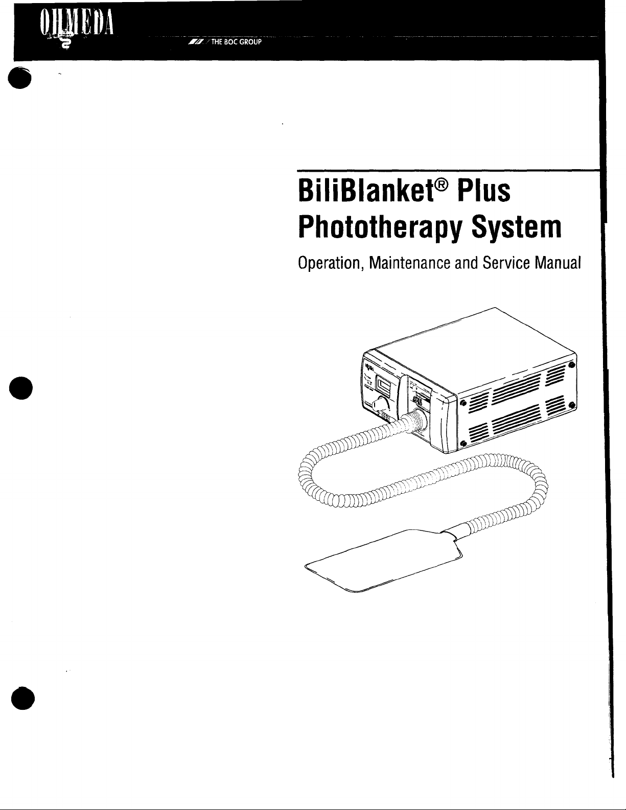
The
light
disposable
ideal
On
through a flexible
from
pneumothoraces.
The
with a four
a
tion
The
The
transmitted.
Although
mately
this
Ohmeda
from a high
400
units
with
the
cable
BiliBlanket
variable
near
light
reflector
the
manual
BiliBlanket
cover
to
550
the
is
Plus
foot
long
power
the
lamp.
source
is
coated
This
there
will
same
available
intensity
that
nanometer
transilluminator
light
used
fiber
supply
lamp
bulb
be a slight
light
for
answering
Plus
Phototherapy
lamp
to a woven
is in
contact
range
pipe
to
appear
to
facilitate
Phototherapy
optic
cable.
for
the
light
is a high
with a dichroic
is
intensity
intensity,
specifically
degradation
throughout
option,
guestions
System
fiber
optic
with
the
patient.
for
phototherapy
unfiltered
at
the
tip
of
vascular
system
source, a cooling
manufactured
sticks
consists
The
light
tungsten
surface
over
its
source
which
time,
life.
which
may
uses a fiber
pad.
The
pad
The
patient
treatment.
light
in
the
visible
the
transilluminator
or
injections.
of a
light
unit
system
halogen
reduces
for
use
the
It
source
contains a lamp,
and
bulb
the
with
the
bulb
will
arise.
optic
cable
to
is
placed
is
exposed
is
also
overheating
with a built-in
infrared
BiliBlanket
maintain
to
spectrum
cable.
The
used
unit
and a light
light
energy
approxi-
deliver
in
a
light
in
the
travels
light
to
find
pad
filters,
protec-
reflector.
Plus.
6600
0228
000
04/22/96
1-1
Page 6
1/General
A
eter
allowed
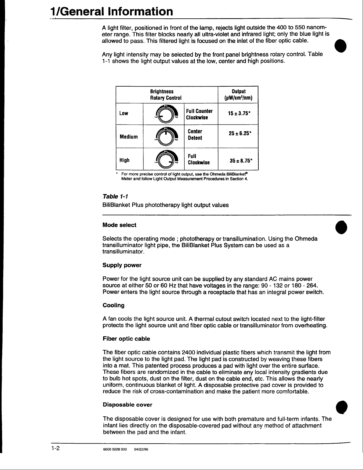
Any
1-1
Information
light
filter,
range.
to
light
shows
Low
Medium
.
High
*
For
Meter
positioned
This
filter
pass.
intensity
the
light
more
precise
and
follow
blocks
This
filtered
may
be
output
Brightness
Rotary
EN
©
se
control
Light
in
front
selected
values
Control
== | Clockwise
of
light
Output
of
the
nearly
all
light
is
focused
by
at
the
Full
Counter
Clockwise
Center
Detent
Full
output,
use
Measurement
lamp,
rejects
ultra-violet
on
the
the
front
panel
low,
center
(pW/cm?/nm)
the
Ohmeda
Procedures
BiliBlanket®
in
light
outside
and
infrared
inlet
of
brightness
and
high
Output
15+3.75
2046.25
*
*
*
35 + 8.75"
Section
4.
the
light;
the
fiber
rotary
positions.
400
only
optic
control.
to
550
the
cable.
nanom-
blue
Table
light
is
Table
1-1
BiliBlanket
Mode
Selects
transilluminator
transilluminator.
Supply
Power
source
Power
Cooling
A
fan
protects
Fiber
The
the
light
into a mat.
These
to
bulb
uniform,
reduce
select
the
power
for
at
enters
cools
the
optic
fiber
optic
source
fibers
hot
continuous
the
Plus
phototherapy
operating
light
the
light
either
50
the
the
light
light
source
cable
cable
to
This
patented
are
randomized
spots,
risk
of
light
dust
cross-contamination
light
output
mode ; phototherapy
pipe,
the
BiliBlanket
source
or
the
unit
60
Hz
source
source
contains
blanket
unit. A thermal
unit
light
pad.
process
on
the
can
be
that
have
through a receptacle
and
fiber
2400
The
produces a pad
in
the
filter,
dust
of
light. A disposable
values
or
transillumination.
Plus
supplied
voltages
cutout
optic
cable
individual
light
cable
pad
to
on the
and
plastic
is
eliminate
make
System
by
in
cable
can
any
standard
the
range:
that
has
switch
or
transilluminator
fibers
constructed
with
light
any
end,
protective
the
patient
Using
be
used
AC
90 - 132
an
integral
located
which
by
weaving
over
local
intensity
etc.
This
pad
more
the
Ohmeda
as
a
mains
power
or
180 - 264.
power
next
to
the
from
overheating.
transmit
the
cover
comfortable.
these
entire
gradients
allows
is
the
the
provided
switch.
light-filter
light
from
fibers
surface.
due
nearly
to
Disposable
The
disposable
infant
between
6600
0228
lies
directly
the
000
cover
pad
04/22/96
cover
on
and
is
designed
the
disposable-covered
the
infant.
for
use
with
pad
both
without
premature
any
and
full-term
method
infants.
of
attachment
The
Page 7
1/General
Information
Disposable
A
disposable
disposable
phototherapy
and
full-term
Transilluminator
The
transilluminator
source
to
the
vest
vest
vest,
treatment.
infants
tip.
is
designed
it
is
possible
who
light
The
disposable
can’t
pipe
to
secure
to
hold
and
tolerate
contains
the
fiber
nurse
cover
having
plastic
optic
the
infant
should
the
vest
fibers
pad
be
used
secured
which
to
the
while
continuing
for
around
transmit
infant.
With
premature
the
light
from
the
infants
midsection.
the
light
6600 0228
000
04/22/96
1-3
Page 8
1/General
Information
Light
source
controls,
indicators
and
connectors
Nontransilluminator
Phototherapy
4.
Wernlag:
Connect
Pad
intense
Light
Prior
to
to
Unit
Syste:
Operation
C1.17.019,020,016
1-4
Figure
Light
source,
6600
0228
1-1
000
pad
and
04/22/96
transilluminator
cable
Page 9
1/General
Information
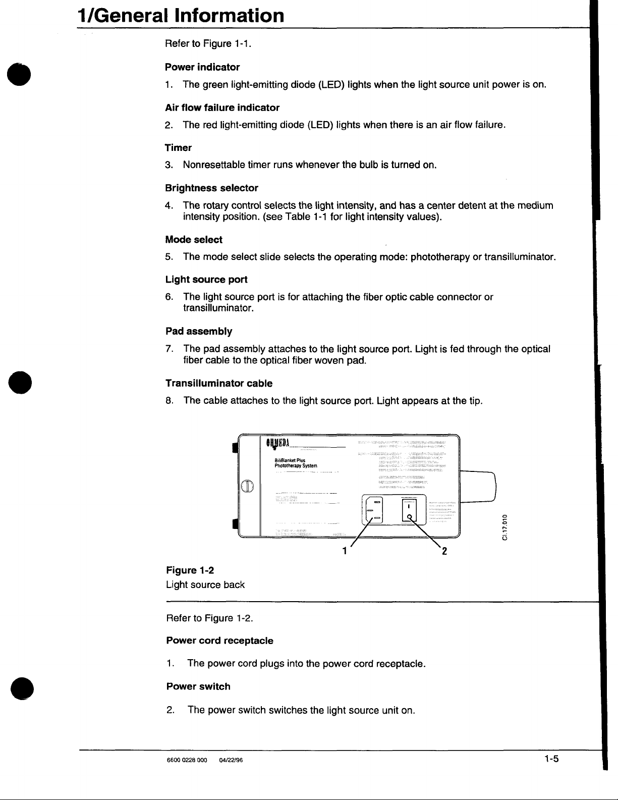
Refer
to
Figure
1-1.
Power
1.
Air
2.
Timer
3.
Brightness
4.
indicator
The
green
flow
failure
The
red
light-emitting
Nonresettable
selector
The
rotary
intensity
Mode
select
5.
The
mode
Light
source
6.
The
light
transilluminator.
Pad
assembly
7.
The
pad
fiber
cable
light-emitting
indicator
diode
timer
runs
control
position.
select
port
source
assembly
to
port
the
selects
(see
slide
is
attaches
optical
diode
(LED)
whenever
the
Table
selects
for
attaching
to
fiber
(LED)
lights
light
intensity,
1-1
for
the
operating
the
light
woven
tights
when
the
bulb
light
the
fiber
source
pad.
when
the
there
is
turned
and
has a center
intensity
values).
mode:
optic
port.
light
source
is
an
air
flow
on.
detent
phototherapy
cable
connector
Light
is
fed
unit
power
failure.
at
the
medium
or
transilluminator.
or
through
the
optical
is
on.
Transilluminator
8.
The
cable
attaches
Figure
Light
Refer
Power
1.
1-2
source
to
Figure
cord
The
power
back
receptacle
cable
1-2.
cord
to
AED
BiliBlanket
Phototherapy
plugs
the
into
light
Plus
System
the
source
power
port.
cord
receptacle.
Light
appears
at
the
tip.
C1.17.010
Power
2.
6600
The
0228
switch
power
000
04/22/96
switch
switches
the
light
source
unit
on.
1-5
Page 10
1/General
Information
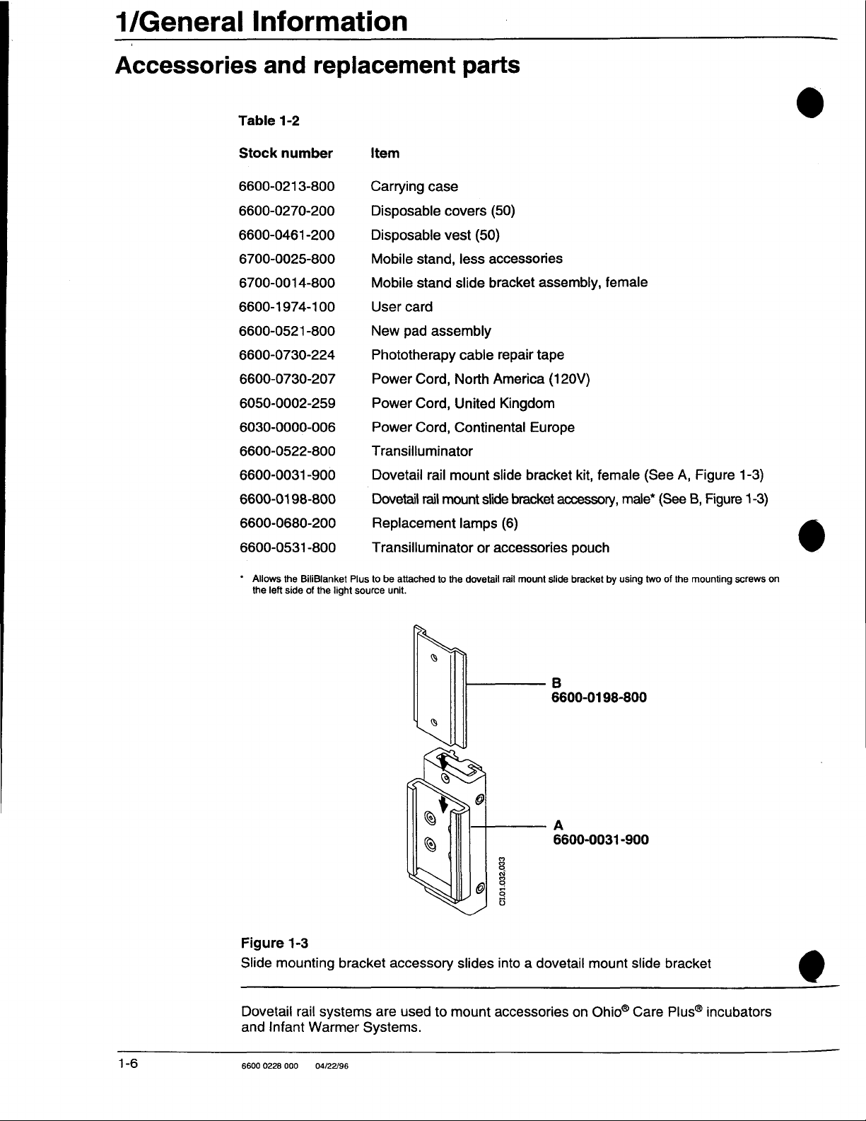
Accessories
Table
Stock
6600-0213-800
6600-0270-200
6600-0461-200
6700-0025-800
6700-0014-800
6600-1974-100
6600-0521-800
6600-0730-224
6600-0730-207
6050-0002-259
6030-0000-006
6600-0522-800
6600-0031-900
and
1-2
number
replacement
Item
Carrying
Disposable
Disposable
Mobile
Mobile
User
New
Phototherapy
Power
Power
Power
Transilluminator
Dovetail
case
stand,
stand
card
pad
assembly
Cord, North
Cord,
Cord,
rail
parts
covers
vest
(50)
(50)
less
accessories
slide
bracket
cable
repair
America
United
Continental
mount
slide
assembly,
tape
Kingdom
Europe
bracket
(120V)
kit,
female
female
(See
A,
Figure
1-3)
6600-0198-800
6600-0680-200
6600-0531
*
Allows
the
left
the
side
-800
BiliBlanket
of
the
Dovetail
Replacement
Transilluminator
Plus
to
source
be
unit.
light
rail
mount
slide
bracket
lamps
attached
to
the
or
accessories
dovetail
(6)
rail
mount
C1.01.032,033
accessory,
pouch
slide
bracket
B
6600-0198-800
A
6600-0031-900
male*
by
using
two
(See
of
the
B,
Figure
mounting
1-3)
screws
9
on
1-6
Figure
Slide
mounting
Dovetail
and
Infant
6600 0228
000
1-3
rail
bracket
systems
Warmer
04/22/96
accessory
are
used
Systems.
to
mount
slides
into a dovetail
accessories
on
mount
Ohio“
slide
Care
bracket
Plus®
incubators
0
Page 11
In
this
section
WARNING
Checkout
Using
Using
A
procedure
the
BiliBlanket
the
Transilluminator
Do
not
use
flammable
conditions.
Factors
Lamp
*
e
e
*
Bulb
The
which
light
output
Lamp
variations
Brightness
Vibration
and
Non-recommended
variations
light
output
before
operation
Plus
Phototherapy
eee
the
BiliBlanket
anesthetics; a possible
affect
light
and
life
are
selector
setting
mechanical
output
affected
shock
Plus
and
lamp
from
bulb
to
bulb
may
i
System
Phototherapy
explosion
life
by
various
vary
by
as
ss.
factors
much
System
hazard
among
as
10%.
in
the
exists
which
presence
under
are:
σος
these
2-2
2-3
이
2-6
of
Intensity setting
The
bulb
life
will
vary
Table
2-1
provides
Brightness
Table
2-1
Brightness
Vibration
Vibration
taken
be
mounted
when
knob
and
mechanical
and
mechanical
moving
or
placed
greatly
an
example.
knob
Low
Medium
High
setting
effect
the
light
on a surface
with
setting
on
shock
shock
source.
the
intensity
bulb
life
will
significantly
To
maximize
which
is
at
which
the
light
Nominal
source
bulb
10,000
life
hours:
is
operated.
1,500
the
life,
exposed
800
bulb
the
life.
Care
light
to
should
source
vibration.
should
be
reduce
the
bulb
stable
and
not
6600 0228
000
04/22/96
2-1
Page 12
2/Operation
CAUTIONS
Checkout
À
Allow
the
light
light
source
ZX
To
ensure
the
proper
performance
System.
À
Use
only
Ohmeda
transilluminators
damage
Non-recommended
Using any
BiliBlanket
light
source
the
lamp
Plus
or
the
procedure
Before
steps
phototherapy
procedure
operating
should
assumes
be
treatment
source
or
changing
the
proper
lamp
as
of
and
from
unit.
lamps
other
than
system
fiber
before
the
Ohmeda
taken
to
that
to
operation
listed
may
light
other
that
will
affect
optic
ensure
or
the
you
cool
for a minimum
the
bulb.
and
light
in
the
Appendix.
result
in
damage
pad
assemblies
manufacturers
recommended
the
performance
pad
or
transilluminator.
operation
BiliBlanket
that
transilluminator
are
familiar
Plus
the
BiliBlanket
with
of
ten
minutes
intensity,
Use
to
or
transilluminator
can
and
Phototherapy
delivers
the
unit’s
replace
of
other
the
BiliBlanket
affect
performance
distributed
of
and
may
Plus
will
the
proper
controls.
before
-
the
lamps
Plus
cables.
by
Ohmeda
result
System,
provide
light.
moving
lamp
only
will
affect
Phototherapy
Light
and
for
the
in
damage
the
following
effective
This
checkout
the
with
the
pads
may
to
or
the
CAUTIONS
A\
Lamp
or
bumping,
for
at
A
Do
not
abrasive
ZA
Observe
guidelines:
e
İf
you
rary
when
to
use
+
Do
+
Do
Not
observing
¢
damage
*
damage
+
decrease
Checkout
life
is
greatly
or
least
ten
allow
the
surfaces.
the
following
hang
storage
removing
it.
not
lay
the
not
place
the
the
light
procedure
reduced
if
the
minutes
fiber
The
the
fiber
on
an
it
for
fiber
anything
the
guidelines
cable’s
cable’s
intensity
unit
is
moved
before
optic
cable,
protective
fiber
optic
optic
cable
IV
pole,
use.
Carefully
optic
cable
on the
may
outer
protective
optical
at
the
if
the
lamp
moving
pad
coverings
cable
and
door,
wall
or
fiber
cause
fibers,
light
or
the
light
source
while
the
bulb
is
the
unit.
or
transilluminator
may
be
and
pad
assembly
pad
or
transilluminator
hook
or
similar
lift
the
cable
free
transilluminator
optic
cable
excessive
conduit,
pad
or
transilluminator.
where
or
transilluminator.
stress
is
hot.
Allow
to
damaged.
and
item,
do
of
obstructions
it
could
and
subjected
the
rub
on
transilluminator
assembly
not
be
to
bulb
sharp
for
pull
the
when
crushed.
may:
shock
to
cool
or
tempo-
cable
ready
2-2
1.
Place
locate
2.
Verify
The
6600 0228
the
the
that
air
000
light
light
the
filter
should
04/22/96
source
source
air
on
within a few
circulation
be
free
a flat,
level
vents
from
surface
feet
of
the
on
the
sides
excessive
(or
use
treatment
of
the
amounts
the
mounting
location.
light
of
lint.
source
slide
bracket)
are
unobstructed.
to
Page 13
2/Operation
CAUTION
CAUTION
WARNING
ZX
Do
not
3.
Examine
signs
of
4.
Connect
5.
Fully
engage
port.
A
Do
not
sharp
6.
Select
will
light.
7.
Using
the
ensure
8.
Select
A A hot
the
light
light
block
the
damage.
the
power
scratch
or
heavy
“|”
on
the
brightness
that
light
“O”
on
surface
source
source
the
power
the
fiber
or
power
is
the
is
port
air
intake
cord,
Replace
cord
to
optic
soil
the
objects
switch
selector
being
power
switch
exposed
port.
whether
or
outlet.
fiber
optic
them
the
light
cable
light-input
on
the
to
switch
emitted
to
when
Do
not
the
cable and
if
they
are
source
connector
end
fiber
optic
turn
the
on
from
the
turn
the
the
insert
lamp
transilluminator
damaged.
first
and
or
transilluminator
of
the
pad,
power
on.
the
front
pad.
power
fiber
optic
fingers
is
on
or
then
connector
vest
or
The
panel,
off.
cable
or
foreign
off.
cable
to
the
line
into
cable.
connecting
green
select
any
is
disconnected
objects
power
the
power
light
for
obvious
supply.
light
Do
not put
cable.
indicator
intensity
into
source
light
and
from
the
Using
WARNING
the
BiliBlanket
The
disposable
infant
lies
pad and
А
If
there
cover
System
with
Plus
1.
When
2.
When
3.
When
or
The
disposable
term
infants
disposable
The
infant,
will
continue
covered,
cover
directly
the
on
infant.
is a concern
the
patient’s
to
shield
conventional
may
not
using
the
pad
the
patient
abdomen.
vest
who
cannot
cover
should
along
with
to
receive
light-emitting
Plus
is
designed
the
covered
eyes
them
phototherapy
be
necessary
the
vest.
is
kept
is
secures
tolerate
be
the
light
effective
section
Phototherapy
for
use
with
both
pad
about
when
or
when
against
clothed
the
having
used.
pad,
phototherapy
of
without
exposure
using
under
the
after
fiber-optic
may
the
pad
any
to
the
the
BiliBlanket
lights.
these
patient’s
applying
pad
the
vest
be
covered
treatment
remains
System
premature
method
direct
BiliBlanket
Eye
conditions:
to
the
secured
in
of
light
Plus
patch
back.
the
pad
infant.
around
or
wrapped
as
contact
and
full-term
attachment
from
the
Plus
is
used
use
with
to
the
patient’s
For
premature
the
in a blanket.
long
as the
with
the
infants.
between
light
pad,
Phototherapy
in
conjunction
the
BiliBlanket
chest
and
full-
midsection,
The
disposable-
skin.
The
the
the
infant
The
disposable
pad and
with a new
6600 0228
the
000
cover
infant's
cover.
04/22/96
should
skin.
The
disposable
If
the
be
the
only
disposable
cover
material
cover
should
also
between
becomes
be
the
light-emitting
soiled,
replaced
it
should
between
side
of
be
replaced
patients.
the
2-3
Page 14

2/Operation
Important:
The
Pad
scribed
must
above.
тт
I
| I
b 4
|!
1.
Inserting
pad
be
Do
4
into
covered
not
use
LI)
i
JD
the
light
the
cover.
with the
the
Pad
disposable
without
the
cover
or
disposable
disposable
2.
Adhesive
fastened
cover
tabs
around
the
vest
or
vest.
optic
as
de-
cable.
Figure
Inserting
2-1
1.
Inserting
pad
the
light
=
into
pad
~
the
light
the vest.
into
the
cover
or
vest
2.
Adhesive
fastened
optic
tabs
around
cable.
C1.01.007,008,009,010
the
WARNINGS
2-4
ZA
ZA
6600
The
light
exposed
an
electric
Never
warmer
0228
000
source
to
shock
place
or
bassinet;
04/22/96
unit
liquids.
hazard.
the
light
is
not
Liquids
source
these
waterproof.
that
enter
inside
conditions
the
Locate
the
infant
expose
the
unit
can
compartment
the
unit
damage
infant
where
it
it
and
of a incubator,
to
possible
will
not
create
injury.
be
Page 15

2/Operation
1.
source
the
Mount
the
place
it
so
can
Insert
the
fiber-optic
disposable
pad
all
BiliBlanket
that
it
sits
on a flat,
be
placed
pad
vest
goes
the
way
in
Plus
System
flat
on
into a new,
over
the
to
the
solid
its
clear
end
side
of
on a radiant
surface
or
within a few
upright.
disposabie
illuminating
the
vest/cover.
warmer,
cover
side
of
See
incubator,
feet
of
or
vest.
the
pad.
Figure
the
The
Be
2-1.
or
stand,
baby.
white
sure
The
side
to
insert
or
light
of
the
Secure
2-1.
Connect
outlet.
Firmly
there
light
knocked
Lay
(side
side
at
*
*
‧
When
hold
Set
prescribed.
9.
Turn
the
the
place
is
no
source
over
the
covered
without
of
the
the
infant's
as
much
pad
as
is
there
is
disposable
the
baby’s
using
the
pad
the
brightness
the
power
cover
or
power
cord
the
fiber-optic
pressure
as a safety
when
the
light
label)
facing
pad
with
the
feet.
See
of
the
infant’s
possible
nothing
the
cover
eyes
vest,
in
position
between
are
variable
switch
vest
around
to
the
cable
or
strain on the
precaution
cable
pad
on the
up.
tip
of
the
Figure
skin
(diapers
the
(clothing
not
directly
wrap
the
and
secure
intensity
to
on.
the
light
source
connector
to
is
pulled
mattress
Place
pad
2-2.
is
in
may
infant's
may
be
exposed
strap
pad
cable
cable.
help
beyond
the
infant’s
at
the
Ensure
direct
be
worn)
skin
worn
section
it
with
knob
on
with
and
plug
into
the
The
cable
prevent
its
or
other
back
baby’s
that:
contact
and
over
the
to
the
snug
the
tape
the
front
the
adhesive
into a grounded
light
source
disconnects
the
light
source
length
during
flat
surface
or
chest
shoulders
with
the
lighted
the
light
pad
pad)
covered
around
tabs.
light
the
See
panel
tabs.
port.
easily
from
treatment.
with
illuminating
directly
and
the
section
other
pad.
infant’s
Figure
to
the
intensity
See
Figure
electrical
Ensure
from
being
on
the
pad’s
cable
of
the
than
the
mid
section
2-3.
level
that
the
side
white
to
The
baby
may
be
clothed
phototherapy
the
skin
results
hold
and
Important:
patient's
Figure
Placing
6600 0228
treatment
(it
is
light
in
the
isomerization
nurse
Be
skin.
2-2
the
infant
000
04/22/96
from
the
sure
onto
as
the
infant
while
that
the
the
or
bundled
long
pad
of
the
in a blanket
as
the
lighted
penetrating
bilirubin
molecule).
continuing treatment.
maximum
pad
with
area
cover
and
section
the
outer
of
illumination
will
continue
of
the
few
millimeters
Using
is
pad
the
in
contact
to
remains
vest,
receive
in
of
skin
it
is
possible
with
effective
contact
which
to
the
with
С1.01.028
2-5
Page 16

2/Operation
1.
Place
infant
with a disposable
on
light
vest.
pad
covered
2.
Secure
disposable
vest
around
σι.01.027,029
infant.
CAUTION
Using
WARNING
the
Figure
Placing
A\
10.
2-3
the
Lamp
or
bumping,
for
at
When
remove
infant
life
is
least
the
treatment
the
onto
greatly
or
if
the
ten
minutes
pad and
the
pad
reduced
unit
is
completed,
vest.
transilluminator
A\
Light
from
the
tip
of
the
heating
particularly
sider
heat
.
Remove
=
.
Using
©
.
Insert
AR
.
Turn
の
.
Adjust
DO
.
When
of
the
if
you
lowering
burn.
the
phototherapy
the
mode
the
transilluminator
power
switch
the
light
intensity
the
transilluminator
skin.
notice
the
tight
select
on.
Reposition
slide
with
vest
if
the
lamp
is
moved
before
Remove
tranilluminator
redness
output
fiber
switch,
light
using
is
no
moving
switch
with
optic
pipe
the
variable
longer
while
and
the
of
cable
select
into
or
the
light
source
the
bulb
is
hot.
the
unit.
off
the
light
source
discard
tip
the
light
needed,
the
disposable
is a form
of
the
transilluminator
the
skin.
In
this
intensity
from
the
light
transilluminator.
port.
intensity
knob.
return
to
is
subjected
Allow
power
vest.
of
energy
case
you
control
source.
phototherapy
knob
the
bulb
switch
and
often,
may
to
to
and
can
avoid
mode.
shock
to
cool
cause
con-
@
2-6
.
Turn
off
the
power
switch.
© a
.
Disconnect
0
.
Using
一
o
.
Connect
6600
0228
000
the
the
04/22/96
mode
the
transilluminator
selector
phototherapy
switch,
light
cable
pipe.
select
to
the
phototherapy.
light
port.
0
Page 17

3/Maintenance
In
this
section
Maintenance
Naintenance
Operator
Service
Cleaning
Bulb
Cleaning
Attaching
and
replacement
the
the
schedule
Maintain
Operator
After
Weekly
Quarterly:
the
each
or
schedule........................................
maintenance
maintenance
disinfecting
.9
fan
filter
dovetail
unit
in
accordance
.................
ii
RARA
ee
.................
rail
bracket
sise
with
the
information
ии
RAR
ecenin
линии
RRE
below:
RARE R RR
maintenance
patient:
after
each
patient:
Replace
Clean
the
the
light
source
the
unit.
accumulation
Clean
the
air
the
phototherapy
cables.
disposable
Check
(see
and
vacuum
filter.
and
RRA
RR RR
RR
RR
nr re
naU
cover
or
vest.
the
air
filter
Figure
4-6)
for
clean
if
Clean
the
light
transilluminator
ини
naa
rc
nanananones
ss
on
the
side
lint
and
dust
necessary.
input
end
of
connector
3-1
3-1
3-1
3-1
3-2
3-4
3-4
of
Cleaning
WARNING
CAUTIONS
Note:
This
it
appears
ronment.
Service
Annually
According
care
institution
electrical
and
disinfecting
À
Make
source
А
Never
circuited,
ZN
Never
is
the
minimum
dirty,
depending
maintenance
to
your
health
protocol
equipment
sure
the
before
immerse
causing
immerse
cleaning
on
for
light
source
cleaning
the
light
permanent
the
pad, vest
frequency.
the
concentration
Perform
described
Ensure
emitted.
Measurement
power
and
that
source
in
damage.
or
connecting
the
that
Refer
cord
the
unit
liquid.
The
air
filter
of
lint
and
electrical
in
section
the
required
to
Light
Procedures.
is
disconnected
is
completely
The
electronic
cable
must
dust
in
safety
4/Service.
light
Output
circuitry
in
liquid.
be
cleaned
the
operating
procedures
output
from
dry
is
the
before
can
whenever
envi-
being
power
using
be
short-
it.
А
Z\
6600
Use
light
light
Do
not
0228
000
the
cleaning
source.
source
autoclave
04/22/96
solution
Do
not
causing
or
sparingly
saturate
damage
gas
sterilize
on a cloth
the
unit - excessive
to
internal
the
BiliBlanket
when
solution
components.
Plus
cleaning
the
may
Phototherapy
exterior
flow
into
System.
of
the
the
3-1
Page 18

3/Maintenance
3.
4.
cord
power
the
or
not
the
pad
both
the
outside
sponge.
allow
light
assembly
hospital
use
an
rinse
of
Agueous
may
liguids
to
source
and
agent
disinfectants
abrasive
the
Unplug
Clean
cloth
mycobactericides
Do
Dry
The
using a disinfecting
are
Never
transilluminator.
Thoroughly
the
allow
and
source
light
the
solutions
be
used.
seep
into
the
surface
pad
with a clean,
transilluminator
safe
for
and
cleaner
to
remove
on
source
light
using
which
housing.
soft,
must
use
on
the
mycobactericides
the
pad,
any
cleaning
to
detergent
mild
a
are
both
cloth.
be
cleaned
materials.
the
cable,
for
cool
hospital
without
Aqueous
may
by
the
connector
solution
residue.
minutes.
ten
least
at
a
solution
disinfectants
used.
on
immersing
solutions
or
the
damp
and
by
which
|
CAUTIONS
A\
Do
not
been
A\
Exposing
ultra-violet
ing
solutions
pad’s
solutions,
The
following
Table
3-1
Cleaning
use a phenolic
associated
the
fiber-optic
light
that
light
output.
strong
table
lists
Generic Formulation:
Hydrogen
Sodium
Cavicide®
and
disinfecting
compound
with
elevated
can
cause
discolor
Do
not
acids,
some
peroxide
hypochlorite
solutions
pad’s
plastic
premature
the
pad,
place
strong
alkali,
cleaning
based
bilirubin
cover
breakdown
such
the
pad
or
solutions:
cleaner.
levels
in
to
strong
as
iodine
in
direct
bleach
Maximum
Phenolic
infants.
cleaning
of
the
plastic
solutions,
sunlight.
solutions
concentration
6%
100
parts/million
100%
spray
compounds
solutions
material.
will
Do
not
to
clean
reduce
use
the
level:
have
or
Clean-
the
iodine
pad.
Bulb
WARNINGS
CAUTION
3-2
replacement
A\
Disconnect
bulb
access
4\
Allow
move
Â
To
ensure
the
Ohmeda
will
affect
Phototherapy
6600
0228
000
the
it.
04/22/96
the
door.
bulb
the
proper
bulb
the
performance
System.
power
to
cool
listed
cord
from
for
at
operation
in
Specifications
of,
least
and
and
the
ten
light
may
power
result
source
minutes
intensity,
in
the
in
before
before
replace
Appendix.
damage
opening
attempting
the
bulb
Use
of
other
to,
the
BiliBlanket
to
only
the
re-
with
bulbs
Plus
0
Page 19

3/Maintenance
Note:
tamination
during
clean,
hot.
Refer
1.
Switch
source.
2.
Turn
and
3.
Gently
the
Move
5.
Firmly
Connect
6.
Close
clockwise.
Do
not
touch
of
the
bulb
installation
soft
cloth.
Also,
to
figure
3-1
off
the
the
screw
open
the
door.
move
the
bulb
outward.
the
lever
slide
the
the
pins
the
lamp
the
center
may
or
if
stains
take
light
source
on
the
lever
Disconnect
back
bulb
of
access
result
bulb
next
to
all
the
glass
are
noted,
care
not
and
access
to
its
original
the
way
new
bulb
panel
bulb
or
in
reduced
clean
to
let
the
disconnect
door
the
bulb
the
connector,
position.
into
the
into
the
and
turn
the
the
lamp
the
bulb
the
one
from
socket
bulb
panel
mirror
surface
performance.
bulb
with
wires
touch
power
cord
quarter
right
turn
to
left,
remove
connector.
the
until
it
screw a quarter
with
your
fingers.
If
the
bulb
alcohol
moving
“clicks”
and
dry
the
reflector
from
the
power
counter-clockwise
the
lever
bulb,
and
discard.
into
position.
turn
is
touched
with
when
and
Con-
a
it
is
WARNING
À
Do
lamp
7.
Bulb
ulb
not
operates
Perform
connector
Lever - ㅡ
operate
the
checkout
n
|
the
lamp
with
the
under
pressure
procedure
protective
and
high
detailed
in
compartment
temperature
section
2/Operation.
|
|
door
and
may
Bu
Compartment
一
Bulb
open. The
shatter.
8
CAUTION
Figure
Bulb
replacement
A
Lamp
or
for
6600
0228
3-1
life
is
bumping,
at
least
000
04/22/96
greatly
or
if
the
ten
minutes
reduced
unit
is
before
if
the
moved
moving
lamp
while
or
the
the
the
light
bulb
unit.
source
is
hot.
is
subjected
Allow
the
bulb
to
to
shock
cool
3-3
Page 20

3/Maintenance
Cleaning
Attaching
the
The
checked
The
counter
the
The
sory
stand.
Attach
shown
lamp
the
fan
filter
fan
filter
on
the
and
cleaned
filter
can
be
clockwise.
dovetail
dovetail
rail
compartment
unit
rail
system
Refer
the
in
figure
horizontally
to
male
of
the
mounting
3-2.
side
of
if
needed
removed
The
for
filter
rail
mounting
an
“Accessories
side
bracket
Ohmeda
bracket
Use
two
of
the
or
vertically.
the
light
source
to
prevent
cleaning
may
be
cleaned
by
mounting
allows
incubator,
and
replacement
accessory
of
the
three
light
source,
(see
Figure
air
blockage
turning
by
vacuuming
bracket
the
light
infant
warmer
to
the
Phillips
depending
the
screw
source
parts”
left
head
on
4-6)
should
that
may
on
the
it.
accessory
to
be
or
Multi-Purpose
section
side
of
the
screws
already
whether
be
cause
filter
mounted
for
stock
light
you
visually
over
heating.
one
quarter
on
the
Therapy
numbers.
source
attached
wish
to
as
mount
turn
|
acces-
to
the
0
3-4
Figure
Dovetail
6600
0228
3-2
000
rail
mount
04/22/96
bracket
attachment
(male
bracket
mounting
on
light
source)
C1.17.013
Page 21

In
this
section
In
this
Repair
Troubleshooting
section
policy
i
and
procedure
rei
aran
rerann
nan
nc o AKA P RKK KKK
|
4-1
4-1
4-2
Functional
Repair
Electrical
Light
Illustrated
SchematieS
description
prOCOdUTeS
Replacing a fuse
Replacing
ReplacingthePCboard.............................................
Replacing
Replacing
Replacingthepowersupply.....................................
Replacing
Replacing
Replacingthebulbholder............................................
Replacing
Replacing a bezel/hour
Replacing a front
safety
Ground
KARTS
Output
continuity… せ ee
Measurement
service
e
..oooooccccoccconaccnanconannnanocanonnnnnano
the
light
source
the
cooling
the
brightness
the
thermal
the
optical
the
power
bezel
procedures
parts
1…..u..ssenvsvsessersssensesenn
이 나 나 이 아
아 아
COVeT
.Re
fan
control...
cutout
switch
filter
asseMmbly
inlet
MOdUlE
meter
label
1...
.0.1.101. 이 니 이 이 아 이
아 아
아 아 아 아 마 며 아 마 아 마 아 아 이 아
.......................
eee
.................
nono
nroarcncnann
i
0
eee
아 이 나 어 마 아 아 아 아 아 아 아 아
nes
tsk
아 어 아 아 아 아 아
nro
sense
아 아 아 아
ncnnnn
iii
eee
eee
아 마
마 아 아 아
Renere
아 아 아 아 아 아
rencor
eee
eee
emen
near
nrona
RR RP
oeeoee000eene
아 아 이 이 아 아 나 아 아 이 아 아 이 이 4-11
ener enes
아 아
nana
ronncrnnerannes
RR
RR
πι
υυ-ν
n
nn
n
nné
ss
one
onen
een
ooo
nee n nen
4-10
4-10
i
4-11
4-11
4-11
nens
esse
es
4-13
아 아 아 아
애 애 아 아 이 이 4-17
4-3
4-4
4-5
4-6
4-6
4-6
4-7
4-7
4-8
4-8
4-9
4-9
Г
Repair
WARNING
policy
Do
not
determined
facility.
À
Service
competent
procedures
for
tools
In-Warranty
Repair
Service
personnel
Out-of-Warranty
To
promote
and
parts
having
and
Distribution
listed
procedure
use
malfunctioning
by
the
described
individual
for
the
convenience
and
test
and
service
and
Distribution
may
void
full
reliability,
Center.
in
this
experience
equipment.
equipment
in
more
of
equipment,
of
eguipment
Center.
the
warranty.
have
If
this
manual
in
the
may
repair
warranty
this
manual
as
described
extensive
qualified
or
for
under
Service
Refer
all
repairs
is
not
possible,
be
undertaken
of
devices
Perform
status
and
must
in
repairs
personnel
Ohmeda
warranty
performed
to
the
and
of
this
the
appropriate
normal
be
this
are
service
should
warranty
service
replacement
by
trained
nature.
service
performed
manual.
included
having
be
or
attempted
statement
performed
and
To
repair
procedure
procedures
by a technically
Detailed
in
proper
representatives.
performed
and
maintenance
competent
ensure
drawings
this
manual
knowledge,
at
the
by
unauthorized
for
further
by
Ohmeda
personnel
performance
of
your
and
solely
Ohmeda
details.
Service
of
those
to
6600
0228
000
04/22/96
4-1
Page 22

4/Service
factory
specifications,
manufactured
perform
tion
All
price
Ohmeda
When
clean
in
1. A letter
2.
3.
The
Center
the
pre-operative
and
compliance
out-of-warranty
for
replacement
Service
sending
the
equipment.
the
original
describing
Al
warranty
must
be
included.
Purchase
the
Ohmeda
Return
Contact
address
person
equipment
listed
it
is
recommended
or
sold
by
Ohmeda.
checkout
with
published
repairs
and
equipment
shipping
performed
parts,
labor
Distribution
to
the
Include
container
in
detail
information. A copy
order
Service
should
on
the
number
and
(name
back
and
bill-to
and
then
be
cover
to
that
After
all
procedure
specifications.
by
Ohmeda
charges
Center
Onmeda
the
light
(if
the
difficulties
cover
Distribution
information.
telephone
shipped
of
this
Service
source,
possible)
of
the
the
repair
Center
prepaid
manual.
all
replacement
repair
actions
in
this
will
and
shipping
and
pad
and
and
include:
experienced
invoice
of
or
any
for
number)
to
the
and
manual
reflect
charges
Distribution
power
with
other
applicable
unit
not
details.)
for
operational
Ohmeda
parts
be
tests
are
to
ensure
Ohmeda’s
where
Center
cord.
Package
the
unit.
under
warranty.
inquiries.
Service
those
either
complete,
proper opera-
then
current
applicable.
for
service,
it
securely
documentation
(Contact
and
Distribution
.
ὐ
list
Service
If
your
light
available.
Troubleshooting
CAUTION
А
Insulation
deteriorated
Table
4-1
Troubleshooting
Symptom:
Unit
overheats
automatically
of
pad
pad
Contact
or
assemblies
should
on
become
the
Ohmeda
electrical
insulation
Guide
and
shuts
cycles
on
wiring
on
off
and
damaged,
Service
can
power
off.
cord
1.
2.
3.
both
new
and
Distribution
deteriorate
and
all
other
Recommended
Check
not
Inspect
Check
power
that
blocked.
the
that
switch
the
fan
and
re-manufactured
Center
with
age.
Check
electrical
Action:
air
intake
filter.
Clean
the
fan
is
running
on.
for
details.
wiring.
and
or
pads
for
brittle
outlet
are
replace
with
the
are
or
if
clogged.
@
4-2
6600 0228
000
04/22/96
4.
Turn
5.
Check
being
temperature
6.
Check
light
source.
off
the
that
the
operated
that
the
power
and
environment
in
does
above
35°C
correct
(Part
number
allow
the
unit
that
the
not
have
ambient
(95°F).
lamp
is
installed
6600-0680-200).
to
unit
in
cool.
is
the
Page 23

4/Service
Symptom:
Power
switch
but
the
fan
light
source
does
not
Power
the
but
light
Low
switch
green
no
light
source
light
is
turned
does
not
power
light.
is
turned
power
indicator
is
emitted
port.
intensity
on
operate
indicator
on,
is
from
from
the
and
on,
the
pad.
Recommended
1.
Check
2.
Check
and
properly
and
the
3.
Check
Replace
1.
Disconnect
supply.
Open
the
is
installed
Replace
1.
Check
the
proper
2.
Remove
source
for
dirt
with a soft,
that
vents
that
the
power
connected
line
power
the
fuses
if
necessary.
the
power
Allow
the
bulb
access
and
fully
the
bulb
that
the
brightness
setting.
the
fiber
port.
Check
or
obstructions.
damp
Action:
are
not
cord
source.
in
the
power
cord
bulb
to
door.
connected.
if
the
problem
optic
cable
the
cable
Wipe
cloth.
blocked.
is
in
good
at
both
inlet
from
cool
for
Check
rotary
from
end
cable
condition
the
light
source
module.
the
power
ten
minutes.
that a bulb
persists.
control
the
and
end
is
light
the
clean
at
pad
Functional
Pad
has
developed a hole
plastic
cover.
description
The
BiliBlanket
flexible
source
The
system.
The
one
of
cable
Using
The
mined
light
light
pad
end
the
design
pad.
cable.
at
light
is
covered
patented
by
assembly
and
Pius
The
either
50
source
the
consists
the
light
source.
with a protective
technology,
distributes
power
consists
light
source
or
60
Hz.
of a lamp,
consists
pad
Light
is
light
of
the
in
the
of
the
can
operate
of a bundle
on
the
other
transmitted
plastic
the
pad’s
over
the
light
source,
3.
Check
light
4.
Check
discolored
agents.
1.
Check
pad.
solutions
2.
light
light
end.
through
light
entire
that
source.
that
the
Use
Replace
source
from
filters, a variable
of
optical
The
outer
jacket.
fibers
surface
the
length
the
correct
(Part
the
plastic
by
non-recommended
type
of
only
recommended
on
the
pad.
pad.
and
the
light-emitting
90-132 V or
fibers
with
inlet
end
the
length
are
woven
of
the
of
the
light
bulb
number
pad
cleaning
180-
power
is
of
pad.
supply
an
inlet
located
the
cable
into a flat
Light
cable
is
installed
6600-0680-200).
cover
agent
cleaning
pad
264
VAC
and
at
the
to
configuration.
intensity
and
in
the
has
not
been
cleaning
used
on
the
with
a
power
and a cooling
coupler
the
the size
focal
pad.
is
on
point
The
deter-
of
the
The
transilluminator
source
6600
0228
to
000
the
tip.
04/22/96
light
pipe
contains
plastic
fibers
which
transmit
light
from
the
light
4-3
Page 24

4/Service
Light
The
lamp
between
to
the
optic
cable
filtering
is a tungsten
the
bulb
400
to
550
that
halogen
and
the
nanometer
transmits
fiber
range.
the
light
bulb
optic
to
with
bundle
This
the
pad.
an
integral
essentially
filtered
light
reflector. A light
restricts
is
focused
light
on
the
output
filter
positioned
end
distribution
of
the
fiber
Power
The
50/60
output
Air
The
(FET),
is
circuit
Light
The
(U1)
of
intensity
when
System
Air
an
cable.
source
supply
power
supply
Hz)
15V
voltage.
Flow
Failure
bulb
circuit
Q1,
and
diverted
board
from
schematic.
output
small
PCB
provides a pulse
this
pulse
train,
potentiometer
the
bulb
temperature
flow
from a DC
over-temperature
This
thermal
if
the
cooling
in
the
DC
output
This
DC
consists
the
thermostat.
the
bulb
control
consists
which
is
on.
See
fan
cutout
system
BiliBlanket
supply.
voltage
of
the bulb, the
to
the
of a light
train
to
the
controls
(Brightness
Figure
cools
the
thermal
cutout switch near
switch
malfunctions.
Plus
There
is
connected
When
Air
Flow
output
gate
the
Knob).
4-8
for
system.
monitors
is a universal
is a potentiometer
to
the
small
source
excessive
Failure
intensity
of
on
time
the
and
heat
LED.
control
Q1.
Light
of
the
The
photodiode,
printed
Incoming
the
the
temperature
drain
output
bulb.
circuit
air
light
input
PCB
of
opens
See
Figure
circuit.
is
The
board
is
filtered
source
(90-132
to
allow
and
the
field
the
thermostat,
4-8
The
controlled
duty
cycle
D2,
turns
schematic.
to
remove
end
and
shuts
V~,
180-264
adjustment
the
bul
circuit.
effect
transistor
the
for
the
printed
LM556
on
by
the
is
varied
the
dual
duty
hour
lint.
of
the
fiber
off
the
light
V~
of
the
current
timer
cycle
by
meter
There
optic
@
the
is
CAUTION
Repair
WARNINGS
4-4
A\
Servicing
be
undertaken
sion
of
procedures
ZX
ELECTRICAL
Phototherapy
À
Service
competent
procedures
for
the
tools
and
6600
0228
000
of
this
without
this
service
SHOCK
System’s
described
individual
for
convenience
test
eguipment
04/22/96
product
proper
manual
HAZARD!
in
this
as
more
extensive
of
in
accordance
tools,
which
cover
without
manual
described
gualified
with
test
equipment
is
clearly
Do
not
must
in
this
repairs
personnel
this
and
thoroughly
remove
first
disconnecting
be
performed
manual.
are
inciuded
having
service
and
the
BiliBlanket
Detailed
proper
manual
the
most
should
recent
understood.
Plus
the
power
by a technically
drawings
in
this
manual
knowledge,
never
revi-
cord.
and
solely
Page 25

o
4/Service
Useful
#1
Phillips
3/16
inch
5/16
inch
tools
for
screwdriver
flat
blade
socket
the
mechanical
screwdriver
repair
.05
9/16
3/16
procedures
inch
hex key
inch
socket
inch
socket
are
as
follows.
wrench
Tweezers
Mate-N-Lok
or
equivalent
pin
removal
Replacing a fuse
Refer
to
figure
4-1.
To
replace a fuse
1.
2.
3.
Note:
fuse
Switch
Place
on
To
holder
the
replace
the
door
the
light
the
tip
power
and
arrows
to
ensure
source
of a small
receptacle,
either
the
power
on
correct
fuse,
the
end
tool
off
flat
and
place
switch
of
fuse
3/8
1/4
four
and
disconnect
head
screw
pry
the
the
screw
and
pull
the
fuse
polarity.
inch
inch
inch
driver
fuse
driver
out
the
holder
socket
drive
socket
extension
the
power
under
door
open.
tip
between
holder.
should
cord
the tab
match
set,
those
with
from
next
the
the
the
end
on
power
power
one
the
source.
switch
of
the
inside
fuse
of
the
1
Power
switch
Fuse door
Fuse
holder
|
Power
receptacle
Fuse
Figure
Replacing a fuse
4.
6600 0228
4-1
Replace
000
fuse
with
04/22/96
the
correct
replacement
С1.17.015
fuse.
4-5
Page 26

4/Service
WARNING
À
For
protection
type
and
5..
Insert a new
6.
Perform
Replacing
1.
Disconnectthe
2.
Place
the
screws
3.
Gently
Note:
The
source
4.
Gently
scratch
Replace
Perform
slide
scratch
The
rear
power
inlet
cover
slide
rating
the
checkout
the
light
and
washers.
the
the
finished
panel
module,
is
slipped
the
the
finished
the
cover
the
electrical
against
of
fuse,
fuse
in
the
procedure
light
source
power
cord.
source
cover
in
off,
surfaces.
and
label
however,
off.
replacement
surfaces.
screws
safety
fire
hazard,
as
listed
holder,
cover
its
normal
pulling
are a part
remains
cover
and
washers.
procedures
in
slide
the
detailed
vertical
it
back
of,
onto
replace a fuse
Specifications
holder
back
in
section
position
away
and
fastened
the
light
detailed
from
come
to
source,
near
2/Operation.
and
the
off
the
only
in
in,
and
remove
bezel,
with,
chassis
being
the
end
with
the
Appendix.
close
the
being
the
light
when
careful
of
the
the
four
careful
this
correct
fuse
cover
source
the
light
not
to
section.
door.
not
to
cover.
7.
Perform
the
BiliBlanket
Replacing
Disconnect
2.
Place
the
washers.
3.
Gently
Place
5.
Remove
6.
Remove
Install
Perform
Perform
BiliBlanket
slide
scratch
the
chassis.
on
the
the
Replacing
1.
Disconnect
the
checkout
Plus
the
PC
board
the
power
light
source
the
cover
the
finished
light
source
the
four
nuts
Lift
the
board
the
connectors
replacement
replacement
the
electrical
the
checkout
Plus
in
service.
the
cooling
the
power
procedure
in
service.
cord.
in
its
vertical
off,
pulling
surfaces.
in
its
horizontal
and
washers
out.
from
board.
board
safety
procedures
procedure
fan
cord.
detailed
it
the
board
by
reversing
detailed
in
position.
back
away
position.
which
hold
and
steps
detailed
in
section
Remove
from
The
the
insert
two
near
section
2/Operation
the
four
the
bezel,
circuit
board
circuit
board
them
fully
through
the
end
2/Operation
before
cover
being
is
to
into
five.
of
before
screws
careful
near
the
the
this
placing
and
not
the
fan.
main
sockets
section.
placing
to
the
4-6
2.
3.
4.
6600
Place
washers.
Gently
scratch
Place
washers
fan.
0228
000
the
light
slide
the
the
light
which
04/22/96
source
the
cover
finished
source
hold
in
its
vertical
off,
pulling
surfaces.
in
its
horizontal
the
cooling
position.
it
back
position.
fan
to
the
away
main
Remove
from
Remove
chassis.
the
the
four
bezel,
the
four
Note
cover
screws
being
careful
screws
the
orientation
and
and
not
of
to
the
Page 27

4/Service
5.
If
necessary,
wires.
6.
Disconnect
7.
Lift
8.
Install
on
ment
replacement
9.
Perform
10.
Perform
BiliBlanket
the
the
fan,
snip
the
fan
out.
the
replacement
four
screws
replace
and
the
electrical
the
checkout
Plus
any
fan
power
that
any
fan
orientation.
in
service.
cable
ties
connector
fan
by
secure
cable
ties
safety
procedures
procedure
to
remove
(J2)
reversing
the
fan
to
which
were
detailed
the
fan
from
the
steps
two
the
chassis.
removed.
detailed
in
section
power
circuit
board.
through
When
Be
near
the
2/Operation
leads
from
six.
Use
installing
careful
end
about
of
this
before
the
bundle
Loc-tite
No.
the
replace-
wire
section.
placing
of
222
the
Replacing
1.
Disconnect
.
Place
the
washers.
.
Gently
scratch
4.
Place
5.
Remove
6.
Remove
and
7.
Loosen
8.
Remove
9.
Remove
10.
Remove
11
.
To
12.
Perform
13.
Perform
BiliBlanket
slide
the
remove
reassemble,
the
the
light
the
the
finished
light
the
four
the
two
the
the
two
the
connector
the
heat
the
nut
the
electrical
the
checkout
Plus
brightness
power
cord.
source
source
cover
surfaces.
screws
screws
bezel.
set
screws
shrink
on
the
reverse
safety
procedure
in
service.
in
its
vertical
off,
pulling
in
its
horizontal
that
on
on
(P7)
that
potentiometer
steps
control
position.
it
back
secure
the
from
surrounds
procedures
bezel
the
brightness
the
two
through
detailed
the
printed
Remove
away
position.
fan
and
and
the
control
circuit
the
potentiometer.
and
remove
ten.
detailed
in
section
from
remove
screw
near
the
four
cover
the
bezel,
the
fan.
on the
board.
the
2/Operation
mode
knob
and
potentiometer.
the
end
being
select
remove
of
this
before
screws
careful
slide
the
knob.
section.
placing
and
not
lever,
the
to
Replacing
1.
Disconnect
2.
Place
washers.
Gently
scratch
Place
σι
.
Remove
the
.
Remove
чо
.
Slide
©
.
Install
o
.
Perform
procedure
service.
6600 0228
main
out
000
the
the
the
light
slide
the
the
finished
the
light
the
chassis.
connectors
the
the
new
the
electrical
detailed
04/22/96
power
power
source
cover
source
four
power
board
supply
cord.
in
off,
surfaces.
in
screws
P1
and
supply.
reversing
safety
in
section
its
vertical
pulling
its
(two
it
horizontal
on
either
P2
from
steps 2 through
test
found
2/Operation
position.
back
away
position.
side)
the
power
later
before
Remove
from
that
hold
supply.
7.
in
this
placing
the
four
the
bezel,
the
power
section
the
cover
screws
being
supply
and
the
checkout
BiliBlanket
careful
brackets
Plus
and
not
in
to
4-7
to
Page 28

4/Service
Replacing
1.
Disconnect
Place
2.
.
.
.
.
.
9.
the
washers.
Gently
slide the
scratch
Place
the
toward
Remove
Remove
through
bracket
Remove
board)
Install
and
the
switch.
from
the
replacing
holder,
Perform
the
the
thermal
the
power
light
source
.
cover
the
finished
light
source
front
of
the
mains
the
thermal
the
bulb
access
hole
grommet.
the
connectors
their
replacement
any
the
clip
the
electrical
cord.
in
its
off,
surfaces.
in
its
the
light
wire
harness
cutout
door).
(P9
circuit
board
thermal
cable
ties
should
safety
cutout
vertical
pulling
horizontal
source
(it
switch
Slip
and
sockets.
cutout
which
be
located
procedures
switch
position.
it
back
away
position.
(between
connects
holder
the
switch
P2, the
switch
were
at
the
Remove
from
The
the
front
the
power
screw
and
out
long
connector
by
reversing
removed.
very
base
detailed
the
the
thermal
bezel
washer
of
its
To
mount
of
near
the
four
bezel,
cutout
and
supply
(this
holder
on
the
steps
the
the
metal
end
cover
being
the
to
the
can
and
power
two
switch
of
this
screws
careful
switch
bracket
lamp).
PCB).
be
best
through
supply
through
properly
portion
section.
and
not
the
seven
of
the
to
is
done
in
10.
Perform
BiliBlanket
Replacing
1.
Disconnect
2.
Place
the
washers.
.
Gently
scratch
A
.
Place
the
ao
.
Remove
O
.
Through
NM
.
Slide
out
O
.
Install
the
Replace
9.
Perform
10.
Perform
BiliBlanket
the
checkout
Plus
the
optical
the
light
source
slide
the
the
finished
light
source
the
screw
the
bulb
optical
replacement
any
cable
the
electrical
the
checkout
Plus
in
service.
power
cover
on
access
filter
ties
in
service.
procedure
filter
cord.
in
its
vertical
off,
pulling
surfaces.
in
its
horizontal
the
mode
door,
bracket
mounting
which
safety
procedures
procedure
detailed
assembly
position.
it
back
selector
remove
through
were
the
bracket
removed.
detailed
in
section
Remove
away
from
position.
slide
lever.
the
two
side
opening.
by
reversing
detailed
in
section
2/Operation
the
the
nuts
on
near
the
2/Operation
four
bezel,
the
mode
steps
end
before
cover
being
one
of
this
before
placing
screws
careful
select
slide
through
section.
placing
and
not
lever.
five.
the
to
the
4-8
6600
0228
000
04/22/96
Page 29

4/Service
©
WARNING
Replacing
Â
Allow
remove
1.
Disconnect
2.
Place
washers.
3.
Gently
scratch
4.
Open
5.
Remove
6.
Remove
7.
Install
8.
Reassemble
9.
Perform
the
the
bulb
it.
the
the
light
slide
the
finished
the
bulb
the
the
the
replacement
the
bulb
holder
to
cool
power
source
the
cover
cord.
in
off,
surfaces.
access
bulb.
mounting
the
electrical
light
source
door.
safety
for
at
its
vertical
pulling
screws
bulb
holder.
by
procedures
least
ten
position.
it
back
that
hold
reversing
minutes
Remove
away
from
the
bulb
steps
one
detailed
before
the
the
holder
through
near
the
attempting
four
bezel,
|
to
the
five.
end
cover
being
main
of
this
to
screws
careful
chassis.
and
not
section.
to
10.
Perform
BiliBlanket
Replacing
1.
Disconnect
2.
Place
the
washers.
3.
Gently
scratch
4.
Place
5.
Release
the
tached.
6.
If
terminals
on
new
ule.
7.
Insert
the
slide
the
module.
necessary,
the
replacement
cable
the
outside
the
checkout
Plus
the
the
light
the
the
finished
light
the
one
tie
module
of
in
service.
power
power
source
cover
source
power
Slide
the
snip
any
at a time
(if
one
replacement
the
light
procedure
inlet
cord.
in
its
vertical
off,
pulling
surfaces.
in
its
horizontal
intet
module
module
cable
from
module.
was
removed)
source.
detailed
module
it
back
from
out
of
ties
holding
the
module,
Be
sure
into
in
section
position.
away
position.
the
chassis
the
chassis
the
attaching
to
match
to
hold
the
the
chassis.
2/Operation
Remove
from
by
with
module
each
the
wire
terminals
Make
the
four
the
bezel,
the
two
the
wire
terminals.
one
placement
to
the
sure
the
before
cover
screws
being
careful
screws
to
on
terminals
Remove
the
same
exactly.
replacement
labels
placing
and
not
the
side
still
at-
the
wire
location
Install
face
toward
the
to
of
a
mod-
(©
8.
Reassemble
9.
Perform
10.
Perform
BiliBlanket
6600
0228
000
the
electrical
the
checkout
Plus
04/22/96
the
light
in
service.
source
safety
procedure
by
procedures
reversing
detailed
steps
two
detailed
in
section
through
near
the
2/Operation
five.
end
of
this
before
section.
placing
the
4-9
Page 30

4/Service
Replacing a bezel/hour
1.
Disconnect
Place
2.
washers.
.
Gently
scratch
.
Place
.
Remove
.
Remove
and
.
Loosen
.
Remove
.
Remove
10.
Remove
11.
Remove
remove
the
the
light
slide
the
the
finished
the
light
the
four
the
two
the
the
two
the
connector
the
heat
the
nut
connector
power
source
cover
surfaces.
source
screws
screws
bezel.
set
screws
shrink
on
the
(P8)
cord.
in
its
off,
in
its
that
on
(P7)
that
potentiometer
from
meter
vertical
pulling
it
back
horizontal
secure
the
bezel
on
the
brightness
from
the
surrounds
the
PCB.
position.
Remove
away
position.
the
fan
and
and
the
printed
circuit
the
potentiometer.
and
remove
from
the
remove
screw
on
control
board.
the
the
four
cover
bezel,
being
the
fan.
the
mode
select
knob
and
remove
potentiometer.
screws
careful
slide
the
and
not
to
lever,
knob.
12.
Remove
13.
To
14.
Perform
15.
Perform
BiliBlanket
the
hour
reassemble,
the
electrical
the
checkout
Plus
meter
reverse
in
Replacing a front
A
front
bezel
labe!
may
a
front
bezel
label,
use
1.
Disconnect
2.
Place
easily
Note
gently
Gently
Remove
the
the
light
accessed.
the
exact
pry
and
peel
it
the
protective
power
source
placement
lift
up a corner
back
by
removing
steps 1 through
safety
procedure
service.
bezel
be
the
until
label
replaced
following
cord.
on
its
of
it
is
backing
its
procedures
detailed
without
procedure.
rear
panel
the
label
on
of
the label
off
the
bezel.
from
the
two
mounting
12.
detailed
in
near
section
2/Operation
disassembling
so
the
front
bezel
the
bezel.
With a pointed
enough
replacement
to
grasp
screws.
the
end
the
light
is
facing
it
with
label.
of
this
before
source.
up
instrument,
your
section.
placing
To
replace
and
can
fingers.
the
be
Carefully
opening(s)
into
6600
0228
place.
000
center
on
04/22/96
the
the
cutout(s)
bezel,
of
the
aligning
replacement
the
label
corners
label
over
properly.
the
component
Press
the
whole
label
Page 31

|
4/Service
Electrical
safety
Use
approved
leakage
current.
Ground
Use a low
between
The
ground
Leakage
Follow
1.
2.
*
Less
230/240
any
Less
230/240
at
lf
measured
the
exposed
any
procedures
equipment
continuity
range
ohmmeter
the
ground
resistance
current
test
than
VAC)
than
VAC)
exposed
from
the
pin
on
must
equipment
300
microamperes
measured
metal surface.
300
microamperes
measured
metal
ground
pin
of
and
techniques
or
electrical
the
line
cord
be
less
than
manufacturer's
at
100/120
with the
with the
surface.
the
power
at
100/120
inlet
module
ground
ground
to
test
safety
analyzer
plug
and
0.2
ohm*.
directions
VAC
intact
VAC
wire
on
the
unit,
the
unit’s
exposed
to
(less
for
(iess
open
it
must
ground
to
measure
metal
verify:
than
500
normal
than
500
for
normal
be
less
than
continuity
the
resistance
surface
microamperes
and
reverse
microamperes
and
reverse
0.1
ohm.
and
of
the
polarity
unit.
at
220/
at
at
220/
polarity
6600
0228
000
04/22/96
4-11
Page 32

4/Service
Light
Output
Pad
The
the
With
should
¢
*
*
Transilluminator
With
Light
2
3150
Measurement
Light
Output
measured
lighted
An
4-2
the
Light
be
35
average
(average
portion
Measured
Measured
with a center
other
bandwidths
Figure
the
4-3
Light
Output
1/2
inches
lux.
(Spectral
light
of
Source
uw/cm2/nm
of
six
the
with
an
with a light
wavelength
for
details.
Source
(6.35
cm)
output
the
pad.
set
on the
+25%.
points
center
input
meter
or
center
set.on
from
Irradiañce)
of
the
BiliBlanket
High
The
measured
point
twice).
line
voltage
designed
of
450
nm
frequencies
the
High,
the
lux
meter
is
an
average
setting
irradiated
on
the
I
of
90 - 132
to
measure
the
average
light
lighted
or
and a bandwidth
may
yield
the
transilluminator
input.
The
of
the
light
is:
portion
of
180 - 264
light
in
the
of
60
different
tip
reading
should
irradiated
emitted
pad
as
VAC
50/60Hz.
400
to
nm.
Light
light
output
should
be
from
shown
520
meters
be
located
9000
light
over
the
pad
in
Figure
nm
range
with
values.
+2250/-
See
+
The
six
point
average
has
been
empirically
demonstrated
to
approximate
the
over
all
pad
fight
output
accurately.
4-12
6600
0228
000
04/22/96
Page 33

4/Service
©
®
CI.01.022
Figure
Six
Point
4-2
Light
Average
Response
400
40
420
430
Bandwidth
440
450 460
Wavelength
Central
470
480
(nm)
Wavelength
490
500
510
CI.01.021
520
Total
Wavelength
Figure
Typical
6600
4-3
Phototherapy
0228
000
04/22/96
Light
Meter
Response
4-13
Page 34

4/Service
Illustrated
service
2.
Parts
parts
Part
1.
Bezel
assy*
leads
and 8 pin
Fan
assembly
harness
Foot
kit,
Screw,
Power
230
Fuse T 4.0A
Screw,
(includes
(includes
with 2 pin
pkg 8 with
6-32 x 3/8
supplyassembiy
(5mm x 20
4-40 x 1/4
bezel,
PCB
Connector)
connector)
hardware
Pan
hd,
Pan
hd,
LEDs,
hour
meter
hardware
.…..….............................
and
eee
...................
een
Phillips
withhardware.............................................
mm)
250V
Phillips
eee
Printedcircuitboard........................................ e gene
OND
Screw,
O
Intensity
(set
10.Chassisf.............................
11.
Bezel
English
[6 + 4
Mains
topowersupplyandPCB).............................
Edgegrommetforsheetmetal...................................................
screw,
label
not
shown
input
4-40 x 1/4
knob
with
4-40 x 1/4
(*order
ee
PO
harness
PHHD
hardware
cone
when
replacing
(power
u...
point)
een
inlet
module
eeeeeeeeeeeeeee
bezel)
eee
eee
Stock
6600-0730-206
eee
nn
6600-0730-213
6600-0730-217
nene
6600-0730-215
1503-3074-000
6600-0730-201
6600-0730-204
6600-0730-223
6600-1806-101
6600-1806-102
6600-1806-103
6600-1806-104
6600-1806-105
6600-1806-106
6600-1806-107
6600-0730-203
6600-0730-221
Number
@
@
t
Order
cover
label
set
on
page
4-16
when
replacing
chassis
4-14
6600
0228
000
04/22/96
Page 35

4/Service
"
Figure
Front
4-4
view
exploded
6600
0228
000
04/22/96
4-15
Page 36

4/Service
Part
1.
Power
2
Screws,
3.
Fuse,T3.15A(5mmx20mm)250WV..............................................
4.
Slider
with
5.
Hour
(includeshardwareandhamess|.................................
6.
Screw,
7.
Screw,
8.
Intensity
(includesharness
9.
Port
10.
Filter
11.
Bulbholderassembiywithhardware............................................
12.
Screw,
13.Screwlatchkit......................................
14.
Bulb,pKg 6 .ee
Parts
Thermal
4
4
inlet
assembly
hardware
meter
4-40 x 3/8
4-40 x 1/2
connector
assembly
6-32 x 1/4
not
shown
pin
PCB
pin
power
module
4-40 x 1/4
kit
potentiometer
cutout
connector, 2 pin
supply
with
Flat
and
rubber
Phillips
Phillips
with3pinconnector)......................................
assembly
with
hardware
Phillips
switch
connector)
hardware
hd
DOOt
.................
assembly
(includes
bulb
sus
heat
shrink
connector,
tube,
and
ドド
issues
トー
ииининни
nene
Stock
6600-0730-202
6600-0730-214
トト
ーーー
6600-0730-218
6600-0730-205
6600-0730-216
ss
6600-0730-219
i
6600-0730-212
6600-0730-208
6600-0730-222
6600-0680-200
nné
6600-0730-211
Number
6
4-16
Figure
Back
6600
4-5
view
0228000
exploded
04/22/96
CI.17.005.006
Page 37

|
4/Service
Part
1.
Air
filter
with
2.
Screw,
3.
Screw
4.
Cover
5.
Handle
6.
Screw,
7.
Screw, 6 -32 x 1/4
Parts
Cover
English
FFENCh.........
SpaniSh
German
МаНап
Swedish
6-32 x 1/4
latch
with
with
1/4 - 20x
not
shown
label
set
............
iene
........
een
iii
hardware
Flat
kit
hardwaref
hardware
3/8
PH
(T
order
when
io
ii
Hd
Truss
HD
Hd
slot
replacing
cover
irene
or
chassis)
st
ona
rss
rennes
nene
ein
ee
Stock
6600-0730-209
6600-0730-222
6600-0730-220
6600-0730-210
6600-1808-101
αλα
Number
6600-1808-102
6600-1808-103
6600-1808-107
6600-1808-104
6600-1808-105
6600-1808-106
”
Figure
Handle
6600
0228
4-6
and
000
filter
04/22/96
4-17
Page 38

ni
ê
TI
in
=
©
O
©
E
©
,
©
©
ogs
の
BEN
|
49553
hd
T
|
|
NEUTRAL
Vip
.9
X
eğ
gg
Jas
|
기
|
HOT
BRN
BLUE
P7.
P7
,1
ya
va
-
|
18.6)
8.6
\
+
|
8.4
8.4
γιο
-
|
8.5)
a.
RED
DE
BLK
LED
m
YA
SDD
WHT
*
-
ㆍ
|
Lio)
38.3)
)P8.3
10.1
WI
-
-
+
-
|
10.2)
8.
の
P10.2
8.7
RED
'
CDE
,
・
|
Ja.8/
8.8
τει
GRN
AN
LED
BILI
1.5
P.C.B.
ORG
P3.1/
AN
/93.1
B
LK
RED
TRE
πι
BLK
Swi
BLK
기
ここ
パー
ここ
ニー
ーー
|
177
|
o
DA
C
FUSE
>
|
|
a
| |
FUSE
A,
ebay
2.2)
pel
2,2
REO
CRN/YEL
PI
e
„5
U2.5/
/P2.5
|
_
FU
EEE.
wit
|
TWA
PI.3
M
-
02.67
2.6
POWER
İNLETZEMİ
FİLTER
Pa
7
v5.2
BLK
2
3İ
|
ΑΜ,
Figure
Wiring
4-7
Diagram
BLUE
BLK
BLK
BLK
LPI
z002V13
4-18
6600 0228
000
04/22/96
Page 39

.
4/Service
то
гм
©.
바버
д’
그
一
一
和
8.3
+
flag
"ToP
1
ーー
區,
R9
Dow.
10753
10133
Be.
-一
1
|
RO
mi
>
sz
35
(
Tv.
PN:
αἱ
4
y
Da.
12
10
ggigones
LHSSSCN
J7.2
1
RIO
uu.
M
sz
“Алма
m
--
I
/
©
“om
TRICI
mica
u
В
+
|
e
O
FAN
+
一
z
sk
一
|
RESET!
cxrriz
ao
rese12
E
PO
pl
CA
(品
了
kno
.
2047TN
TS.
=
207
746,
3JcNrmu
mesmo
[12
2v.
10493
II
ÅD
BRIGHTNESS
2
니
015
burst
애
1
м
DiscH2
13
M
y
7
1%
ul
<
ite
aL
Як
,
2%.
5
au
IN4002CI
0!
。
©)
ΤΡΙ
_
r——_—_rr__"
9.5
do
POWER
SUPPLY
+
Figure
Printed
6600 0228
lare
J9.1
POVER
SUPPLY
-
4-8
Circuit
000
04/22/96
LIARIOT
8
一
|
Board
Аст
Lo
J9.2
8.5
AQ
HOUR
THERMAL
1726,
METER
-
2
fo
RED
LED
-
Schematic
CUT
57
QUI
-
4%
8.4
ÅD
RED
LED
+
of
<Я
i
!
RS
KNOB
|
o
J9.4
(o
ms
+
—
©
1P2
10020119
4-19
Page 40

ADDE
o
Specifications
Note:
Environmental:
Ambient
All
specifications
Operating:
are
nominal
o
Temperature:
and
are
subject
15
to
to
change
35°C
without
(59
to
notice.
95°F).
WARNING
Performance:
Å
Equipment
anesthetics. A possible
Storage
Light
requirement:
bandwidth:
is
not
Humidity:
Atmospheric
suitable
for
explosion
Temperature:
Humidity:
Atmospheric
Intesity © 10%
Intesity
(all
The
infrared
©50%
wavelengths + 15
transilluminator
energy
pressure:
operation
hazard
pressure:
390
nm
563
nm
452
nm
546
nm
nm)
option
0
to
70
kPa
in
—5
0
to
50
blocks
95%
to106
the
exists
to
+50°C
95%
kPa
to
RH
non-condensing
kPa
presence
under
(23
to
RH
non-condensing
106
kPa
ultraviolet
of
flammable
these
122°F).
and
conditions.
Bulb
Light
output:
(Spectral
Mode
of
t
Factory
calibrated
on
the
accuracy
Type:
Life:
6600
0228
000
Irradiance)
Operation:
using a light
of
the
light
04/22/96
High
brightness:
Designed
meter
meter
used.
Ohmeda
with an
for
accuracy
Stock
Specifically
specifications
Nominally
light
intensity
continuous
of + 1pw/cm/nm.
Number
designed
for
the
800
hours
setting
35
uW/cm?/nm + 8.75
uW/cm?/nm
See
Light
Procedures
9,000 + 2250/-3150
maximum
for
Output
on
intensity
transilluminator.
operation.
Light
output
6600-0680-200
to
meet
light
intensity
BiliBlanket
at
25°C
and
Plus
(77°F)
ambient;
continuous
phototherapy
Measurement
page
4-12.
lux
is
setting
measurement
(carton
and
may
of
six
focal
Phototherapy
tested
operation.
+.
for
the
vary
depending
lamps).
length
System.
at
high
A-1
Page 41

Appendix
|
Physical
(All
dimensions
are
nominal)
Electrical
Light
source
Fiber
optic
Fiber
optic
Fiber
optic
Transilluminator:
Protection
ingress
Input:
light
cables:
pad:
against
of
water:
unit:
pad:
Size:
Weight:
Size:
Illuminated
Length:
Length:
Not
protected.
2.2 A at
1.1 A at
100-120
220-240
area:
Vac
Vac
10.56 x 4.31 x 10.27
in
(26.82 x 10.95 x 26.09
Less
than 8 pounds
(entire
4.38 x 9.38
4.00 x 6.00
47
2400
mat
the 4 x 6 inch
48
system).
in
(1.19
m)
optic
fibers
providing
in
(1.2m)
in
in
(3.64
(11.12 x 23.83
(10.16 x 15.2
woven
total
illumination
area.
(Wx H x
cm)
kg)
cm)
cm)
into
a
L)
of
Safety
Standards
Fusing:
Overheat
Chassis
current:
Ground
impedance:
protection:
leakage
250
watts
maximum
180-264
Two
Fuse
Thermal
(239°F),
IEC
IEC
Less
(less
(power
polarity
polarity.
Less
on
Designed
VAC ~ 50/60
primary
on
Type B equipment.
Class 1 equipment
than
than
than
the
fuses
the
power
cutout switch
removing
300
500
on)
with
and
with
0.1
unit
to
to
meet:
at
90-132,
Hz
for
all
voltages
supply
near
power
to
designed
microamperes
microamperes
the
ground
the
ground
ohm
from
ground
any
exposed
UL544,
CSA
board
the
lamp
the
lamp.
at
100/120
at
220/230/240
intact
open
pin
metal
IEC
601-1-M90
T
3.15A,
T
4.0A, 5 x
actuates
for
continuous
for
normal
for
normal
of
the
surface
601-1
VAC
and
and
power
on
the
and
5 x
20mm,
20mm,
at
115°C
operation.
VAC)
reverse
reverse
inlet
unit.
IEC
601-1-2,
250V
250V
module
0
A-2
6600 0228
000
04/22/96
 Loading...