

Ohmeda 7900 User manual

7900 Ventilator
Supplemental to the Datex-Ohmeda Excel SE
and Modulus SE Anesthesia Machine Service Manual.
Ventilator Software Revision 2.X

1
503-0151-000
3/27/97

Ohmeda 7900 Anesthesia Ventilator
Supplement to Excel SE and Modulus SE Anesthesia Machine Service Manual
Ventilator Software Revision 2.X
1
503-0151-000
3/27/97

1
503-0151-000
3/27/97

Table of Contents
1/ Introduction
1.1. What this manual includes . . . . . . . . . . . . . . . . . . . . . . . . . . . . . . . . . . . . . . . . . .1-2
1.2. Symbols . . . . . . . . . . . . . . . . . . . . . . . . . . . . . . . . . . . . . . . . . . . . . . . . . . . . . . .1-3
1.3. Standard Service Procedures . . . . . . . . . . . . . . . . . . . . . . . . . . . . . . . . . . . . . . .1-4
Operation and Service Manuals . . . . . . . . . . . . . . . . . . . . . . . . . . . . . . . .1-4
Ventilator Tests . . . . . . . . . . . . . . . . . . . . . . . . . . . . . . . . . . . . . . . . . . . . .1-4
1.4. 7900 Ventilator Configuration . . . . . . . . . . . . . . . . . . . . . . . . . . . . . . . . . . . . . . .1-5
Software Versions . . . . . . . . . . . . . . . . . . . . . . . . . . . . . . . . . . . . . . . . . . .1-5
2/ Theory of Operation
2.1. General . . . . . . . . . . . . . . . . . . . . . . . . . . . . . . . . . . . . . . . . . . . . . . . . . . . . . . .2-1
7900 Ventilator Features . . . . . . . . . . . . . . . . . . . . . . . . . . . . . . . . . . . . . .2-2
Safety Features . . . . . . . . . . . . . . . . . . . . . . . . . . . . . . . . . . . . . . . . . . . . .2-3
2.2. Mechanical . . . . . . . . . . . . . . . . . . . . . . . . . . . . . . . . . . . . . . . . . . . . . . . . . . . . . .2-3
2.3. Electrical . . . . . . . . . . . . . . . . . . . . . . . . . . . . . . . . . . . . . . . . . . . . . . . . . . . . . . .2-9
Power Supply Assembly . . . . . . . . . . . . . . . . . . . . . . . . . . . . . . . . . . . . .2-10
Power Supply . . . . . . . . . . . . . . . . . . . . . . . . . . . . . . . . . . . . . . .2-10
Synchrononus step-down regulator . . . . . . . . . . . . . . . . . . . . . . .2-13
External Interface . . . . . . . . . . . . . . . . . . . . . . . . . . . . . . . . . . . . . . . . . .2-14
Communication Interface (RS232C) . . . . . . . . . . . . . . . . . . . . . . . . . . . .2-14
External Interface Connector . . . . . . . . . . . . . . . . . . . . . . . . . . . . . . . . . .2-14
Sealed Lead Acid Battery . . . . . . . . . . . . . . . . . . . . . . . . . . . . . . . . . . . .2-14
Input . . . . . . . . . . . . . . . . . . . . . . . . . . . . . . . . . . . . . . . . . . . . . . . . . . . .2-14
Output . . . . . . . . . . . . . . . . . . . . . . . . . . . . . . . . . . . . . . . . . . . . . . . . . . .2-14
Microcontroller Assembly . . . . . . . . . . . . . . . . . . . . . . . . . . . . . . . . . . . .2-15
Functional Specifications . . . . . . . . . . . . . . . . . . . . . . . . . . . . . . .2-15
Program Memory . . . . . . . . . . . . . . . . . . . . . . . . . . . . . . . . . . . . . . . . . . .2-17
Flash EPROM . . . . . . . . . . . . . . . . . . . . . . . . . . . . . . . . . . . . . . .2-17
System RAM . . . . . . . . . . . . . . . . . . . . . . . . . . . . . . . . . . . . . . . .2-17
Non-Volatile Memory . . . . . . . . . . . . . . . . . . . . . . . . . . . . . . . . . .2-17
Safety Relevant Computing . . . . . . . . . . . . . . . . . . . . . . . . . . . . . . . . . . .2-17
Watchdog Systems . . . . . . . . . . . . . . . . . . . . . . . . . . . . . . . . . . . . . . . . .2-18
68040 Software Watchdog Timer . . . . . . . . . . . . . . . . . . . . . . . .2-18
Operating Mode Watchdog . . . . . . . . . . . . . . . . . . . . . . . . . . . . .2-18
Error Response Sequence . . . . . . . . . . . . . . . . . . . . . . . . . . . . .2-18
DATA Acquisition . . . . . . . . . . . . . . . . . . . . . . . . . . . . . . . . . . . . . . . . . .2-19
Analog to Digital Converter System . . . . . . . . . . . . . . . . . . . . . . .2-19
Multiplexer and Buffer Amplifier . . . . . . . . . . . . . . . . . . . . . . . . . .2-20
A/D Converter . . . . . . . . . . . . . . . . . . . . . . . . . . . . . . . . . . . . . . .2-20
Voltage Reference . . . . . . . . . . . . . . . . . . . . . . . . . . . . . . . . . . . .2-21
Flow Valve Control . . . . . . . . . . . . . . . . . . . . . . . . . . . . . . . . . . . .2-21
Gas Inlet Valve Drive Circuit . . . . . . . . . . . . . . . . . . . . . . . . . . . . . . . . . .2-22
Front Panel Display Interface . . . . . . . . . . . . . . . . . . . . . . . . . . . . . . . . .2-22
EL Display Controller . . . . . . . . . . . . . . . . . . . . . . . . . . . . . . . . . .2-22
Video Display Memory . . . . . . . . . . . . . . . . . . . . . . . . . . . . . . . . .2-22
Membrane Switch Inputs . . . . . . . . . . . . . . . . . . . . . . . . . . . . . . .2-22
LED Driver Outputs . . . . . . . . . . . . . . . . . . . . . . . . . . . . . . . . . . .2-22
Rotary Encoder Input . . . . . . . . . . . . . . . . . . . . . . . . . . . . . . . . . .2-22
Mechanical Ventilation Switch . . . . . . . . . . . . . . . . . . . . . . . . . . .2-23
Audio Alarm . . . . . . . . . . . . . . . . . . . . . . . . . . . . . . . . . . . . . . . . . . . . . . .2-23
Manifold Pressures . . . . . . . . . . . . . . . . . . . . . . . . . . . . . . . . . . . . . . . . .2-23
Front Panel Assembly . . . . . . . . . . . . . . . . . . . . . . . . . . . . . . . . . . . . . . .2-23
Sensor Interface Board (SIB) . . . . . . . . . . . . . . . . . . . . . . . . . . . . . . . . .2-24
1503-0151-000 3/27/97 i

Table of Contents
Inspiratory and Expiratory Flow Measurement . . . . . . . . . . . . . .2-24
Patient Airway Pressure Measurement . . . . . . . . . . . . . . . . . . . .2-24
O2 Concentration Measurement . . . . . . . . . . . . . . . . . . . . . . . . .2-25
Switch Connections . . . . . . . . . . . . . . . . . . . . . . . . . . . . . . . . . . .2-25
3/ Post Service Checkout
Test the Ventilator. . . . . . . . . . . . . . . . . . . . . . . . . . . . . . . . . . . . . . . . . . . . . . . . . . . .3-1
Test the Anesthesia System. . . . . . . . . . . . . . . . . . . . . . . . . . . . . . . . . . . . . . . . . . . .3-1
Test all Options and Accessories. . . . . . . . . . . . . . . . . . . . . . . . . . . . . . . . . . . . . . . . .3-1
4/ Tests and Troubleshooting
4.1. Overview . . . . . . . . . . . . . . . . . . . . . . . . . . . . . . . . . . . . . . . . . . . . . . . . . . . . . . .4-1
Testing Requirements . . . . . . . . . . . . . . . . . . . . . . . . . . . . . . . . . . . . . . . .4-1
4.2. Service Mode Menu . . . . . . . . . . . . . . . . . . . . . . . . . . . . . . . . . . . . . . . . . . . . . . .4-3
4.3. Diagnostic Tests . . . . . . . . . . . . . . . . . . . . . . . . . . . . . . . . . . . . . . . . . . . . . . . . . 4-4
Test CPU . . . . . . . . . . . . . . . . . . . . . . . . . . . . . . . . . . . . . . . . . . . . . . . . . .4-4
Test External RAM . . . . . . . . . . . . . . . . . . . . . . . . . . . . . . . . . . . . . . . . . .4-5
Test Display RAM . . . . . . . . . . . . . . . . . . . . . . . . . . . . . . . . . . . . . . . . . . .4-5
Test Flash ROM . . . . . . . . . . . . . . . . . . . . . . . . . . . . . . . . . . . . . . . . . . . .4-6
Test EEPROM . . . . . . . . . . . . . . . . . . . . . . . . . . . . . . . . . . . . . . . . . . . . . .4-7
Test Panel Switches . . . . . . . . . . . . . . . . . . . . . . . . . . . . . . . . . . . . . . . . .4-8
Test Serial Ports . . . . . . . . . . . . . . . . . . . . . . . . . . . . . . . . . . . . . . . . . . .4-10
Test Flow Valve . . . . . . . . . . . . . . . . . . . . . . . . . . . . . . . . . . . . . . . . . . . .4-11
Test Gas Inlet Valve (GIV) . . . . . . . . . . . . . . . . . . . . . . . . . . . . . . . . . . .4-12
Gas Inlet Valve FAIL Instructions: . . . . . . . . . . . . . . . . . . . . . . . 4-12
Test Pressure Limit Switch . . . . . . . . . . . . . . . . . . . . . . . . . . . . . . . . . . .4-13
Pressure Limit Switch FAIL Instructions: . . . . . . . . . . . . . . . . . . .4-14
4.4. Diagnostic tools. . . . . . . . . . . . . . . . . . . . . . . . . . . . . . . . . . . . . . . . . . . . . . . . . .4-15
Display A/D channels . . . . . . . . . . . . . . . . . . . . . . . . . . . . . . . . . . . . . . .4-15
Display I/O signals . . . . . . . . . . . . . . . . . . . . . . . . . . . . . . . . . . . . . . . . . .4-16
Display Battery Charge Status . . . . . . . . . . . . . . . . . . . . . . . . . . . . . . . .4-17
System Error Log . . . . . . . . . . . . . . . . . . . . . . . . . . . . . . . . . . . . . . . . . .4-18
System Error Log Codes . . . . . . . . . . . . . . . . . . . . . . . . . . . . . . . . . . . . .4-19
Verify Flow . . . . . . . . . . . . . . . . . . . . . . . . . . . . . . . . . . . . . . . . . . . . . . . .4-23
4.5. Calibrations . . . . . . . . . . . . . . . . . . . . . . . . . . . . . . . . . . . . . . . . . . . . . . . . . . . .4-24
Calibrate O2 Sensor . . . . . . . . . . . . . . . . . . . . . . . . . . . . . . . . . . . . . . . .4-24
Calibrate Flow Sensors . . . . . . . . . . . . . . . . . . . . . . . . . . . . . . . . . . . . . .4-25
Calibrate Pressure Sensitivity . . . . . . . . . . . . . . . . . . . . . . . . . . . . . . . . .4-28
Calibrate Flow Valve . . . . . . . . . . . . . . . . . . . . . . . . . . . . . . . . . . . . . . . .4-30
Calibrate Bleed Resistor . . . . . . . . . . . . . . . . . . . . . . . . . . . . . . . . . . . . .4-31
Sensor(s) Cal Due . . . . . . . . . . . . . . . . . . . . . . . . . . . . . . . . . . . . . . . . . .4-34
4.6. User Settings . . . . . . . . . . . . . . . . . . . . . . . . . . . . . . . . . . . . . . . . . . . . . . . . . . .4-35
Select Altitude . . . . . . . . . . . . . . . . . . . . . . . . . . . . . . . . . . . . . . . . . . . . .4-35
Select Drive Gas . . . . . . . . . . . . . . . . . . . . . . . . . . . . . . . . . . . . . . . . . . .4-35
Adjust Brightness . . . . . . . . . . . . . . . . . . . . . . . . . . . . . . . . . . . . . . . . . .4-36
Select Heliox Mode . . . . . . . . . . . . . . . . . . . . . . . . . . . . . . . . . . . . . . . . .4-36
Exit Service Mode . . . . . . . . . . . . . . . . . . . . . . . . . . . . . . . . . . . . . . . . . .4-37
4.7. Troubleshooting Guides . . . . . . . . . . . . . . . . . . . . . . . . . . . . . . . . . . . . . . . . . . .4-38
Troubleshooting Mechanical/Electrical . . . . . . . . . . . . . . . . . . . . . . . . . .4-38
Troubleshooting by Alarm Messages . . . . . . . . . . . . . . . . . . . . . . . . . . .4-40
ii 1503-0151-000 3/27/97

Table of Contents
5/ Maintenance
5.1. Maintenance Schedule . . . . . . . . . . . . . . . . . . . . . . . . . . . . . . . . . . . . . . . . . . . .5-1
Maintenance . . . . . . . . . . . . . . . . . . . . . . . . . . . . . . . . . . . . . . . . . . . . . . .5-1
Yearly Maintenance Checks . . . . . . . . . . . . . . . . . . . . . . . . . . . . . . . . . . .5-1
Two Year Maintenance . . . . . . . . . . . . . . . . . . . . . . . . . . . . . . . . . . . . . . .5-1
5.2. Maintenance Procedures . . . . . . . . . . . . . . . . . . . . . . . . . . . . . . . . . . . . . . . . . . .5-2
Exhalation Valve Maintenance . . . . . . . . . . . . . . . . . . . . . . . . . . . . . . . . .5-2
Supply Gas Inlet Filter . . . . . . . . . . . . . . . . . . . . . . . . . . . . . . . . . . . . . . . .5-2
Free Breathing Valve Maintenance . . . . . . . . . . . . . . . . . . . . . . . . . . . . . .5-3
6/ Repair Procdures
6.1.General . . . . . . . . . . . . . . . . . . . . . . . . . . . . . . . . . . . . . . . . . . . . . . . . . . . . . . .6-1
Assemblies -- tools for removal and installation . . . . . . . . . . . . . . . . . . . .6-1
6.2. Removing the 7900 ventilator from the Ohmeda Excel/Modulus SE Gas Machine 6-2
Removing the 7900 ventilator from the integrated machine . . . . . . . . . . .6-2
Removing the 7900 ventilator from the non-integrated machine . . . . . . . .6-4
6.3. Setting up the Service Shelf . . . . . . . . . . . . . . . . . . . . . . . . . . . . . . . . . . . . . . . . .6-7
6.4. Removing the top cover . . . . . . . . . . . . . . . . . . . . . . . . . . . . . . . . . . . . . . . . . . . .6-9
6.5. Printed circuit board and power module removal . . . . . . . . . . . . . . . . . . . . . . . .6-11
Removing the Power Supply circuit board and the Microcontroller circuit
board . . . . . . . . . . . . . . . . . . . . . . . . . . . . . . . . . . . . . . . . . . . . . . . . . . . .6-11
Removing Power Supply circuit board . . . . . . . . . . . . . . . . . . . . . . . . . .6-11
Removing Microcontroller circuit board . . . . . . . . . . . . . . . . . . . . . . . . . .6-14
Firmware Replacement Procedure . . . . . . . . . . . . . . . . . . . . . . . . . . . . .6-16
Software Upload Procedure . . . . . . . . . . . . . . . . . . . . . . . . . . . . .6-17
Ohmeda Software Upgrade Tool . . . . . . . . . . . . . . . . . . . . . . . . .6-17
To Install Ohmeda Software Upgrade Tool . . . . . . . . . . . . . . . . .6-17
To Install 7900 Software Field Upgrade. . . . . . . . . . . . . . . . . . . .6-18
To Perform Software Upgrade . . . . . . . . . . . . . . . . . . . . . . . . . . .6-18
Microcontroller board . . . . . . . . . . . . . . . . . . . . . . . . . . . . . . . . . . . . . . . .6-18
Removing the front panel . . . . . . . . . . . . . . . . . . . . . . . . . . . . . . . . . . . .6-19
Replacing the display board . . . . . . . . . . . . . . . . . . . . . . . . . . . . . . . . . .6-19
Replacing the encoder switch . . . . . . . . . . . . . . . . . . . . . . . . . . . . . . . . .6-21
Removing the battery . . . . . . . . . . . . . . . . . . . . . . . . . . . . . . . . . . . . . . .6-22
Testing After Maintenance . . . . . . . . . . . . . . . . . . . . . . . . . . . . . . . . . . .6-23
6.6. Replacing the isolation transformer . . . . . . . . . . . . . . . . . . . . . . . . . . . . . . . . . .6-24
Removing the power module . . . . . . . . . . . . . . . . . . . . . . . . . . . . . . . . . 6-24
Prepare power module for removal . . . . . . . . . . . . . . . . . . . . . . . . . . . . .6-25
Isolation transformer removal . . . . . . . . . . . . . . . . . . . . . . . . . . . . . . . . .6-26
Alarm speaker removal . . . . . . . . . . . . . . . . . . . . . . . . . . . . . . . . . . . . . .6-27
Power cord inlet removal . . . . . . . . . . . . . . . . . . . . . . . . . . . . . . . . . . . . .6-28
6.7. Pneumatic subassembly removal . . . . . . . . . . . . . . . . . . . . . . . . . . . . . . . . . . .6-29
Removing the non-relieving regulator . . . . . . . . . . . . . . . . . . . . . . . . . . .6-29
Removing the flow control valve . . . . . . . . . . . . . . . . . . . . . . . . . . . . . . .6-30
Removing the solenoid and gas inlet valve assembly . . . . . . . . . . . . . . .6-32
Removing the GIV assembly . . . . . . . . . . . . . . . . . . . . . . . . . . . .6-32
Removing the solenoid switch . . . . . . . . . . . . . . . . . . . . . . . . . . .6-32
6.8. Gas Inlet Valve Repair . . . . . . . . . . . . . . . . . . . . . . . . . . . . . . . . . . . . . . . . . . . .6-33
Removing the Mechanical Over-pressure Bleed Off valve (MOBO)
assembly . . . . . . . . . . . . . . . . . . . . . . . . . . . . . . . . . . . . . . . . . . . . . . . . .6-35
MOBO removal (See figure 6-30) . . . . . . . . . . . . . . . . . . . . . . . . . . . . . .6-36
MOBO installation and low pressure operation check . . . . . . . . . . . . . .6-36
1503-0151-000 3/27/97 iii

Table of Contents
Mechanically cycle MOBO weights (See figure 6-30) . . . . . . . . . . . . . . .6-38
Removing the Drive gas check valve assembly . . . . . . . . . . . . . . . . . . .6-39
Removing the pressure sensing switch assembly . . . . . . . . . . . . . . . . . .6-40
6.9. SIB Removal from Excel/Modulus SE . . . . . . . . . . . . . . . . . . . . . . . . . . . . . . . .6-41
SIB (Sensor Interface Board) Assembly Removal . . . . . . . . . . . . . . . . . .6-42
Replacement Calibration Instructions (SIB) . . . . . . . . . . . . . . . . . . . . . .6-43
6.10. Patient Interface Harness Removal from Excel SE . . . . . . . . . . . . . . . . . . . . .6-43
6.11. Patient Interface Panel/Harness Assembly Removal From Modulus SE . . . . .6-44
6.12. SIB/Machine INterface Harness Removal . . . . . . . . . . . . . . . . . . . . . . . . . . . .6-46
6.13. Test unit after repair as follows . . . . . . . . . . . . . . . . . . . . . . . . . . . . . . . . . . . .6-46
7/ Illustrated Parts List
7.1. General . . . . . . . . . . . . . . . . . . . . . . . . . . . . . . . . . . . . . . . . . . . . . . . . . . . . . . .7-1
Special Instructions . . . . . . . . . . . . . . . . . . . . . . . . . . . . . . . . . . . . . . . . . .7-1
Stock Numbers for Replacement Parts . . . . . . . . . . . . . . . . . . . . . . . . . . .7-1
7.2. 7900 SERVICE KITS: . . . . . . . . . . . . . . . . . . . . . . . . . . . . . . . . . . . . . . . . . . . . .7-1
SIB Harnesses . . . . . . . . . . . . . . . . . . . . . . . . . . . . . . . . . . . . . . . . . . . .7-16
8/ Schematics
9/ Accessories, Miscellaneous Parts
7900 Accessory and Bellows Mounting Kits: . . . . . . . . . . . . . . . . . . . . . . . . . . . . . . .9-1
O&M Manuals: . . . . . . . . . . . . . . . . . . . . . . . . . . . . . . . . . . . . . . . . . . . . . . . . . . . . . .9-2
iv 1503-0151-000 3/27/97

List of Illustrations
List of Illustrations
Section 2
Figure 2-1 7900 Ventilator - Excel SE and Modulus SE Anesthesia System
Interface. . . . . . . . . . . . . . . . . . . . . . . . . . . . . . . . . . . . . . . . . . . . . . . .2-1
Figure 2-2 7900 Ventilator Operational Block Diagram . . . . . . . . . . . . . . . . . . . .2-2
Figure 2-3 Supply gas inlet, filtered . . . . . . . . . . . . . . . . . . . . . . . . . . . . . . . . . . .2-3
Figure 2-4 Gas Inlet Valve . . . . . . . . . . . . . . . . . . . . . . . . . . . . . . . . . . . . . . . . . .2-3
Figure 2-5 Non-Relieving Pressure Regulator . . . . . . . . . . . . . . . . . . . . . . . . . . .2-4
Figure 2-6 Flow Control Valve . . . . . . . . . . . . . . . . . . . . . . . . . . . . . . . . . . . . . . .2-4
Figure 2-7 Exhalation Manifold . . . . . . . . . . . . . . . . . . . . . . . . . . . . . . . . . . . . . . .2-5
Figure 2-8 Drive Gas Check Valve . . . . . . . . . . . . . . . . . . . . . . . . . . . . . . . . . . . .2-6
Figure 2-9 MOBO (Mechanical Over pressure Bleed Off) . . . . . . . . . . . . . . . . . .2-7
Figure 2-10 Bleed Resistor, Pressure Switch and Free Breathing Valve . . . . . . . .2-8
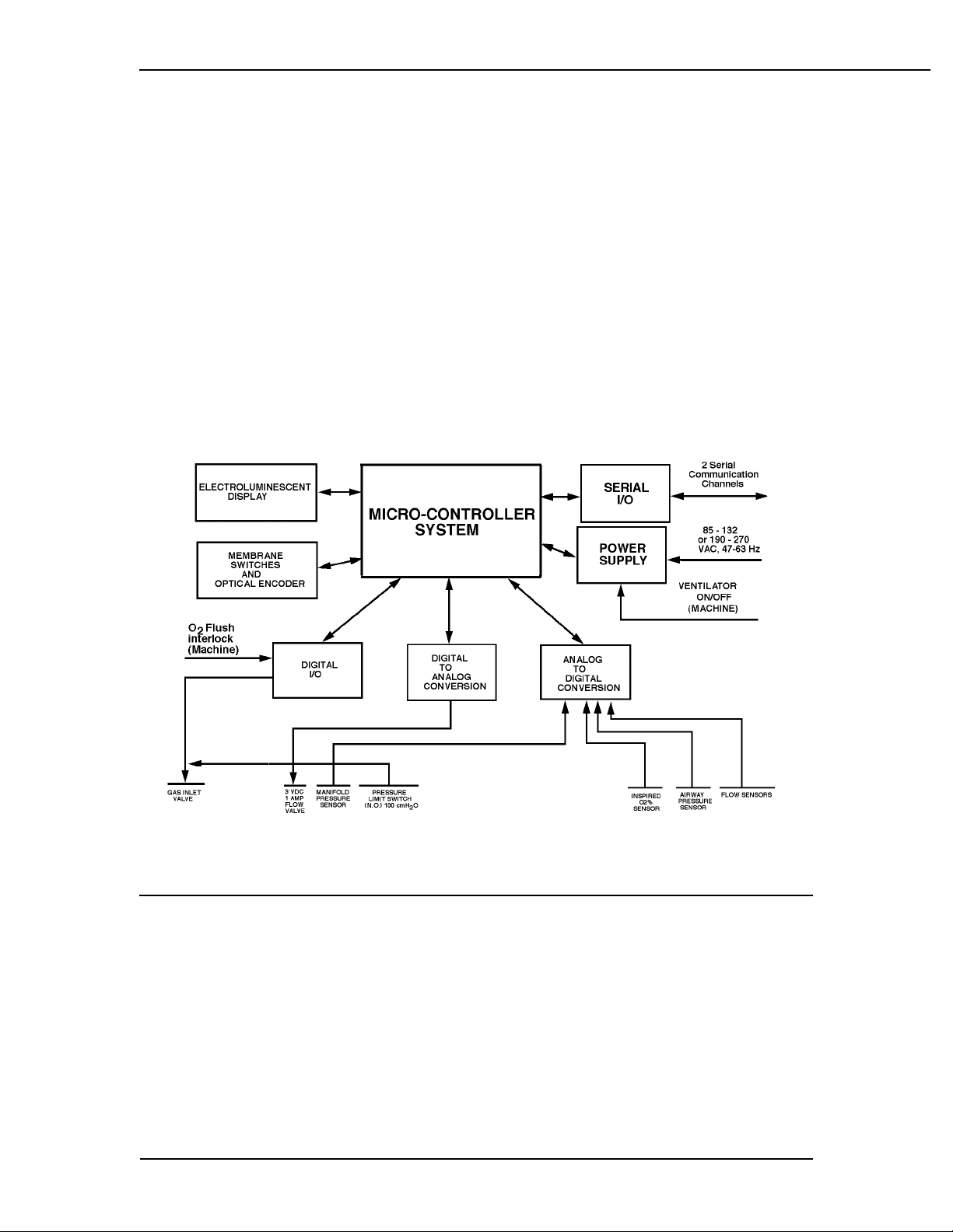
Figure 2-11 Electronic functional block diagram . . . . . . . . . . . . . . . . . . . . . . . . . . .2-9
Section 4
Figure 4-1 Service mode main menu . . . . . . . . . . . . . . . . . . . . . . . . . . . . . . . . . .4-3
Displays Test CPU . . . . . . . . . . . . . . . . . . . . . . . . . . . . . . . . . . . . . . . . . . . . . . 4-4
Test External RAM . . . . . . . . . . . . . . . . . . . . . . . . . . . . . . . . . . . . . . .4-5
Test Display RAM . . . . . . . . . . . . . . . . . . . . . . . . . . . . . . . . . . . . . . . .4-5
Test Flash ROM . . . . . . . . . . . . . . . . . . . . . . . . . . . . . . . . . . . . . . . . .4-6
Test EEPROM . . . . . . . . . . . . . . . . . . . . . . . . . . . . . . . . . . . . . . . . . . .4-7
Test Front Panel . . . . . . . . . . . . . . . . . . . . . . . . . . . . . . . . . . . . . . . . .4-8
Test Serial Ports . . . . . . . . . . . . . . . . . . . . . . . . . . . . . . . . . . . . . . . .4-10
Test Flow Valve . . . . . . . . . . . . . . . . . . . . . . . . . . . . . . . . . . . . . . . .4-11
Test Gas Inlet Valve . . . . . . . . . . . . . . . . . . . . . . . . . . . . . . . . . . . . .4-12
Test Pressure Limit Switch . . . . . . . . . . . . . . . . . . . . . . . . . . . . . . . .4-13
Display A/D Channels . . . . . . . . . . . . . . . . . . . . . . . . . . . . . . . . . . . 4-15
Discrete I/O Signals . . . . . . . . . . . . . . . . . . . . . . . . . . . . . . . . . . . . . .4-16
Battery Charge Status . . . . . . . . . . . . . . . . . . . . . . . . . . . . . . . . . . . .4-17
System Error Log . . . . . . . . . . . . . . . . . . . . . . . . . . . . . . . . . . . . . . .4-18
Verify Flow Output and Flow Sensors . . . . . . . . . . . . . . . . . . . . . . . .4-23
Calibrate O2 Sensor . . . . . . . . . . . . . . . . . . . . . . . . . . . . . . . . . . . . .4-24
Calibrate Flow Sensors . . . . . . . . . . . . . . . . . . . . . . . . . . . . . . . . . . .4-25
Pressure Sensitivity Calibration . . . . . . . . . . . . . . . . . . . . . . . . . . . . .4-28
Flow Valve Calibration . . . . . . . . . . . . . . . . . . . . . . . . . . . . . . . . . . . .4-30
Bleed Resistor Calibration . . . . . . . . . . . . . . . . . . . . . . . . . . . . . . . . .4-31
Sensor(s) Calibration Due . . . . . . . . . . . . . . . . . . . . . . . . . . . . . . . . .4-34
Select Altitude . . . . . . . . . . . . . . . . . . . . . . . . . . . . . . . . . . . . . . . . . .4-35
Select Drive Gas . . . . . . . . . . . . . . . . . . . . . . . . . . . . . . . . . . . . . . . .4-35
Adjust Brightness . . . . . . . . . . . . . . . . . . . . . . . . . . . . . . . . . . . . . . .4-36
Select Heliox Mode . . . . . . . . . . . . . . . . . . . . . . . . . . . . . . . . . . . . . .4-36
Section 5
Figure 5-1 Supply gas filter, Filter assembly with bowl 1503-3319-000,
Filter element 1503-3320-000 . . . . . . . . . . . . . . . . . . . . . . . . . . . . . . .5-2
Figure 5-2 Free Breathing Valve deflection tube and seat removal . . . . . . . . . . .5-3
Figure 5-3 Free Breathing Valve flapper replacement . . . . . . . . . . . . . . . . . . . . .5-4
1503-0151-000 3/27/97 v

List of Illustrations
Section 6
Figure 6-1 Excel 210 with mid-shelf and integrated 7900 ventilator . . . . . . . . . . .6-2
Figure 6-2 Removing the ventilator from an Excel/Modulus SE Anesthesia Gas
Machine . . . . . . . . . . . . . . . . . . . . . . . . . . . . . . . . . . . . . . . . . . . . . . . .6-3
Figure 6-3 Excel 210 without mid-shelf and non-integrated 7900 ventilator . . . . .6-4
Figure 6-4 Non-integrated 7900 ventilator and mounting tray insertion . . . . . . . .6-5
Figure 6-5 Ventilator mounting tray . . . . . . . . . . . . . . . . . . . . . . . . . . . . . . . . . . .6-6
Figure 6-6 Setting up the service shelf . . . . . . . . . . . . . . . . . . . . . . . . . . . . . . . . .6-7
Figure 6-7 Put the ventilator on the service shelf . . . . . . . . . . . . . . . . . . . . . . . . .6-8
Figure 6-8 Removing the top cover screws and cover . . . . . . . . . . . . . . . . . . . . .6-9
Figure 6-9 Sub assembly locations reference . . . . . . . . . . . . . . . . . . . . . . . . . .6-10
Figure 6-10 Disconnecting cables for circuit board removal . . . . . . . . . . . . . . . . .6-11
Figure 6-11 Removing the power supply board . . . . . . . . . . . . . . . . . . . . . . . . . .6-13
Figure 6-12 Microcontroller board connector and cable identification around
manifold pressure transducer . . . . . . . . . . . . . . . . . . . . . . . . . . . . . .6-14
Figure 6-13 Microcontroller board removal . . . . . . . . . . . . . . . . . . . . . . . . . . . . . .6-15
Figure 6-14 Front panel removal . . . . . . . . . . . . . . . . . . . . . . . . . . . . . . . . . . . . .6-19
Figure 6-15 Disconnect cable. . . . . . . . . . . . . . . . . . . . . . . . . . . . . . . . . . . . . . . .6-19
Figure 6-16 Remove display board . . . . . . . . . . . . . . . . . . . . . . . . . . . . . . . . . . . .6-20
Figure 6-17 Replacing the encoder . . . . . . . . . . . . . . . . . . . . . . . . . . . . . . . . . . .6-21
Figure 6-18 Battery removal . . . . . . . . . . . . . . . . . . . . . . . . . . . . . . . . . . . . . . . . .6-22
Figure 6-19 Power Module removal . . . . . . . . . . . . . . . . . . . . . . . . . . . . . . . . . . .6-24
Figure 6-20 Power cord removal . . . . . . . . . . . . . . . . . . . . . . . . . . . . . . . . . . . . .6-25
Figure 6-21 Isolation transformer removal . . . . . . . . . . . . . . . . . . . . . . . . . . . . . .6-26
Figure 6-22 Alarm speaker removal . . . . . . . . . . . . . . . . . . . . . . . . . . . . . . . . . . .6-27
Figure 6-23 Power cord inlet connector removal . . . . . . . . . . . . . . . . . . . . . . . . .6-28
Figure 6-24 Regulator removal . . . . . . . . . . . . . . . . . . . . . . . . . . . . . . . . . . . . . . .6-29
Figure 6-25 Disconnect the flow control valve cable . . . . . . . . . . . . . . . . . . . . . .6-30
Figure 6-26 Flow control valve removal . . . . . . . . . . . . . . . . . . . . . . . . . . . . . . . .6-31
Figure 6-27 Inlet valve and solenoid switch removal . . . . . . . . . . . . . . . . . . . . . .6-32
Figure 6-28 Gas inlet valve exploded view . . . . . . . . . . . . . . . . . . . . . . . . . . . . . .6-33
Figure 6-29 Detail shuttle and U-cup seals . . . . . . . . . . . . . . . . . . . . . . . . . . . . . .6-34
Figure 6-30 Mechanical Over-pressure Bleed Off valve (MOBO) removal . . . . . .6-35
Figure 6-31 MOBO alignment and installation . . . . . . . . . . . . . . . . . . . . . . . . . . .6-37
Figure 6-32 Main manifold bottom view, exhalation manifold removed . . . . . . . .6-38
Figure 6-33 Drive gas check valve removal . . . . . . . . . . . . . . . . . . . . . . . . . . . . .6-39
Figure 6-34 Pressure sensing switch removal . . . . . . . . . . . . . . . . . . . . . . . . . . .6-40
Figure 6-35 SIB cable and pneumatic hose identification . . . . . . . . . . . . . . . . . . .6-41
Figure 6-36 Patient Interface panel cable and pneumatic hose identification.
Replace as an assembly. Shown as an exploded view for tube/
cable routing clarification. . . . . . . . . . . . . . . . . . . . . . . . . . . . . . . . . .6-42
vi 1503-0151-000 3/27/97

List of Illustrations
Section 7
Figure 7-1 Top cover . . . . . . . . . . . . . . . . . . . . . . . . . . . . . . . . . . . . . . . . . . . . . .7-2
Figure 7-2 Top cover ground wire connections . . . . . . . . . . . . . . . . . . . . . . . . . .7-2
Figure 7-3 Isolation barrier gasket, 1503-3018-000 . . . . . . . . . . . . . . . . . . . . . . .7-3
Figure 7-4 Front panel assembly mounting and harnesses . . . . . . . . . . . . . . . . .7-3
Figure 7-5 Front panel key board and bezel . . . . . . . . . . . . . . . . . . . . . . . . . . . . .7-4
Figure 7-6 EL display panel mounting . . . . . . . . . . . . . . . . . . . . . . . . . . . . . . . . .7-4
Figure 7-7 Front panel display assembly harnesses . . . . . . . . . . . . . . . . . . . . . .7-5
Figure 7-8 Encoder, Rotary, 16 position with push button switch. . . . . . . . . . . . .7-5
Figure 7-9 Chassis bottom view . . . . . . . . . . . . . . . . . . . . . . . . . . . . . . . . . . . . .7-6
Figure 7-10 Power module mounting. . . . . . . . . . . . . . . . . . . . . . . . . . . . . . . . . . . .7-6
Figure 7-11 Power module components . . . . . . . . . . . . . . . . . . . . . . . . . . . . . . . . .7-7
Figure 7-12 Alarm speaker . . . . . . . . . . . . . . . . . . . . . . . . . . . . . . . . . . . . . . . . . . .7-7
Figure 7-13 Transformer assembly (exploded view) . . . . . . . . . . . . . . . . . . . . . . . .7-8
Figure 7-14 Battery . . . . . . . . . . . . . . . . . . . . . . . . . . . . . . . . . . . . . . . . . . . . . . . . .7-9
Figure 7-15 Pneumatic manifold mounting . . . . . . . . . . . . . . . . . . . . . . . . . . . . . . .7-9
Figure 7-16 Manifold components . . . . . . . . . . . . . . . . . . . . . . . . . . . . . . . . . . . .7-10
Figure 7-17 Pneumatic manifold O-rings. . . . . . . . . . . . . . . . . . . . . . . . . . . . . . . .7-10
Figure 7-18 Gas inlet valve . . . . . . . . . . . . . . . . . . . . . . . . . . . . . . . . . . . . . . . . . .7-11
Figure 7-19 MOBO (Mechanical Over-pressure Bleed Off) valve . . . . . . . . . . . . .7-12
Figure 7-20 Manifold components (continued) . . . . . . . . . . . . . . . . . . . . . . . . . . .7-13
Figure 7-21 Exhalation manifold latch assembly . . . . . . . . . . . . . . . . . . . . . . . . .7-13
Figure 7-22 Supply gas filter assembly . . . . . . . . . . . . . . . . . . . . . . . . . . . . . . . . .7-14
Figure 7-23 Free breathing valve. . . . . . . . . . . . . . . . . . . . . . . . . . . . . . . . . . . . . .7-14
Figure 7-24 Exhalation manifold valve . . . . . . . . . . . . . . . . . . . . . . . . . . . . . . . . .7-15
Figure 7-25 SIB (Sensor interface board) assembly, 1503-8009-000. . . . . . . . . .7-15
Figure 7-26 Patient interface board assembly. . . . . . . . . . . . . . . . . . . . . . . . . . . .7-16
Section 8
Figure 8-1 System connection block diagram . . . . . . . . . . . . . . . . . . . . . . . . . . . .8-2
Figure 8-2 SIB schematic diagram interface cable connections . . . . . . . . . . . . . .8-3
Figure 8-3 Patient interface cable - Machine side . . . . . . . . . . . . . . . . . . . . . . . .8-4
Figure 8-4 SIB interface, hose and cable routing . . . . . . . . . . . . . . . . . . . . . . . . .8-5
Figure 8-5 7900 SIB schematic diagram, page 1 of 2 . . . . . . . . . . . . . . . . . . . . .8-6
Figure 8-6 7900 SIB schematic diagram, page 2 of 2 . . . . . . . . . . . . . . . . . . . . .8-7
Figure 8-7 Microcontroller board schematic diagram, page 1 of 10 . . . . . . . . . . .8-8
Figure 8-8 Microcontroller board schematic diagram, page 2 of 10 . . . . . . . . . . .8-9
Figure 8-9 Microcontroller board schematic diagram, page 3 of 10 . . . . . . . . . .8-10
Figure 8-10 Microcontroller board schematic diagram, page 4 of 10 . . . . . . . . . .8-11
Figure 8-11 Microcontroller board schematic diagram, page 5 of 10 . . . . . . . . . .8-12
Figure 8-12 Microcontroller board schematic diagram, page 6 of 10 . . . . . . . . . .8-13
Figure 8-13 Microcontroller board schematic diagram, page 7 of 10 . . . . . . . . . .8-14
Figure 8-14 Microcontroller board schematic diagram, page 8 of 10 . . . . . . . . . .8-15
Figure 8-15 Microcontroller board schematic diagram, page 9 of 10 . . . . . . . . . .8-16
Figure 8-16 Microcontroller board schematic diagram, page 10 of 10 . . . . . . . . .8-17
Figure 8-17 Power supply board schematic diagram, page 1 of 5 . . . . . . . . . . . .8-18
Figure 8-18 Power supply board schematic diagram, page 2 of 5 . . . . . . . . . . . .8-19
Figure 8-19 Power supply board schematic diagram, page 3 of 5 . . . . . . . . . . . .8-20
Figure 8-20 Power supply board schematic diagram, page 4 of 5 . . . . . . . . . . . .8-21
Figure 8-21 Power supply board schematic diagram, page 5 of 5 . . . . . . . . . . . .8-22
1503-0151-000 3/27/97 vii

Notes
viii 1503-0151-000 3/27/97

1/Introduction
Important
The information contained in this service manual pertains only to those models of
products which are marketed by Ohmeda as of the effective date of this manual or
the latest revision thereof. This service manual was prepared for exclusive use by
Ohmeda service personnel in light of their training and experience as well as the
availability to them of parts, proper tools and test equipment. Consequently, Ohmeda provides this service manual to its customers purely as a business convenience and for the customer's general information only without warranty of the
results with respect to any application of such information. Furthermore, because
of the wide variety of circumstances under which maintenance and repair activities
can be performed and the unique nature of each individual's own experience, capacity, and qualifications, the fact that customer has received such information
from Ohmeda does not imply in anyway that Ohmeda deems said individual to be
qualified to perform any such maintenance or repair service. Moreover, it should
not be assumed that every acceptable test and safety procedure or method, precaution, tool, equipment or device is referred to within, or that abnormal or unusual
circumstances, can not warrant or suggest different or additional procedures or requirements.
This manual is subject to periodic review, update and revision. Customers are cautioned to obtain and consult the latest revision before undertaking any service of
the equipment. Comments and suggestions on this manual are invited from our
customers. Send your comments and suggestions to the Manager of Technical
Publications, Ohmeda, Ohmeda Drive, Madison, Wisconsin 53707.
CAUTION:
ww
ww
Servicing of this product in accordance with this service manual should
never be undertaken in the absence of proper tools, test equipment and
the most recent revision to this service manual which is clearly and thoroughly understood.
Technical Competence
The procedures described in this service manual should be performed by trained
and authorized personnel only. Maintenance should be undertaken only by competent individuals who have a general knowledge of and experience with devices
of this nature. No repairs should ever be undertaken or attempted by anyone not
having such qualifications.
Ohmeda strongly recommends using only genuine replacement parts made or sold
by Ohmeda for all repair parts replacements.
Special Notice
• Some information in this manual can possibly point the reader to
electronic troubleshooting and component/repair replacement level
of service. This information, when supplied, is only supplied to add
clarity to service or trouble shooting statements. Ohmeda Service
1503-0151-000 5/26/0 1-1

1/ Introduction
Personnel are mandated by Company Policy to service electronic
equipment to a board replacement level only.
• Read completely through each step in every procedure before starting the procedure; any exceptions can result in a failure to properly
and safely complete the attempted procedure.
• Unless otherwise specified, values in this manual are nominal.
• Sections in this manual begin on odd numbered or right-hand pages. If there is no text on the preceding, backup even numbered
page, it is labeled "NOTES:" for your use if you wish.
• Figures that require more than one page have the title and main text
on the left (even numbered) page; Additional figure information is
on the facing (odd numbered) page.
Some terms used in this manual
Note: A Note provides additional information to clarify a statement in text.
Important: An Important statement is similar to a note, but provides a comment
of greater emphasis.
WARNING: ww
CAUTION: ww
ww
A Warning statement, with this symbol, warns the reader of the possibility
of injury to the patient or operator/service person.
ww
A Caution statement with this symbol, cautions the reader of the possi-
bility of damage to the equipment.
1.1. What this manual includes
This manual covers the Ohmeda 7900 Anesthesia Ventilator which is an integral
component in the Ohmeda Excel SE and Ohmeda Modulus® SE Anesthesia Sys-
tems.
Data on the control module troubleshooting, disassembly, repair, reassembly, test-
ing and calibration are included.
The Excel SE and Modulus® SE Anesthesia Gas Machines each have their own
service manuals.
1-2 1503-0151-000 5/26/0

1/Introduction
1.2. Symbols
The following common symbols are used in Ohmeda manuals and on products,
however, no one product nor manual has every symbol listed. Refer to this list concerning various symbols found.
ø
O
o
q
p
œ
†
∏
x
y
On (power)
OFF (power)
Stand-by
Stand-by or preparatory state for a
part of the equipment
ON only for part of
the equipment
“OFF” only for part
of the equipment
Direct Current
Alternating Current
Protective earth
ground
Earth ground
N
ˆ
z
Z
134oC
Í
m
µ
H
w
Movement in one direction
Movement in two directions
Lock
Unlock
Autoclavable
non-autoclavable
Type B equipment
Type BF equipment
Type CF equipment
Warning or Caution, ISO 7000-0434
r
å
Y
t
T
Ê
Frame or chassis
ground
Alarm silence button
Equipotential
wW
π
Attention, consult accompanying documents, IEC 601-1
Dangerous voltage
Input
≈
Variability
Output
Ù
Variability in steps REF. Stock Number
This way up SN Serial Number
1503-0151-000 5/26/0 1-3

1/ Introduction
+
Ë
P
Plus, positive polarity
Minus, negative
polarity
Lamp, lighting, illumination
XXXX
Systems with this mark agree with European Council Directive (93/42/EEC) for
medical devices when they are used as
specified in their Operation and Maintenance Manuals. The xxxx is the certification number of the Notified Body used by
Ohmeda's Quality Systems
Read top of float
1-4 1503-0151-000 5/26/0

1/Introduction
1.3. Standard Service Procedures
Operation and Service Manuals
You must have, and be familiar with, the Operation and Maintenance manuals for
this product. Study the Anesthesia Systems Operation and Maintenance manuals
if you need further information about the operation of the system. You must determine where a problem is located before you can determine which service manual
to use. Refer to the various service manuals or accessory manuals if you require
more information.
Service calibration functions allow Ohmeda trained users and Ohmeda service personnel to perform ventilator setup functions, tests, calibration and measurements from
the front panel display or from commands sent to the proprietary serial port.
Ventilator Tests
Normal operational tests can be performed while the Ventilator is installed in, or attached to, an Anesthesia System. Calibration, troubleshooting or repair may require removing the Ventilator from the Anesthesia Machine.
WARNING: wwww Section "4/Test and Troubleshooting" must be performed whenever you
remove a Ventilator cover, to verify that all critical parts of the Ventilator
are still operational and within specification.
WARNING: wwww After the Ventilator has been serviced, you must perform "Post-Service
Checkout" to verify the entire Anesthesia System is properly functioning
before the system can be returned to clinical use.
WARNING: wwww Do not perform testing or maintenance on this instrument while it is be-
ing used to ventilate a patient, possible injury may result.
1.4. 7900 Ventilator Configuration
The 7900 Ventilator; (hereafter called Ventilator) is an integral part of the Modulus
SE and the Excel SE Anesthesia Systems. This Ventilator is not available for use
as a stand alone piece of equipment.
The Ventilator is composed of two basic units:
• the breathing circuit interface: ABA (Autoclavable Bellows Assembly); Bellows and Bellows Housing,
• the Control Module; containing the control valves, processing circuits, controls, monitors and display screen.
Software Versions
This manual includes test and calibration procedures for Revision 2.X software. As
software is revised and updated, the revision level is displayed on the ventilator
start-up menu.
1503-0151-000 5/26/0 1-5

1/ Introduction
Notes:
1-6 1503-0151-000 5/26/0
V
GS
O2 S
2/Theory of Operation
ZZZ2.1. General
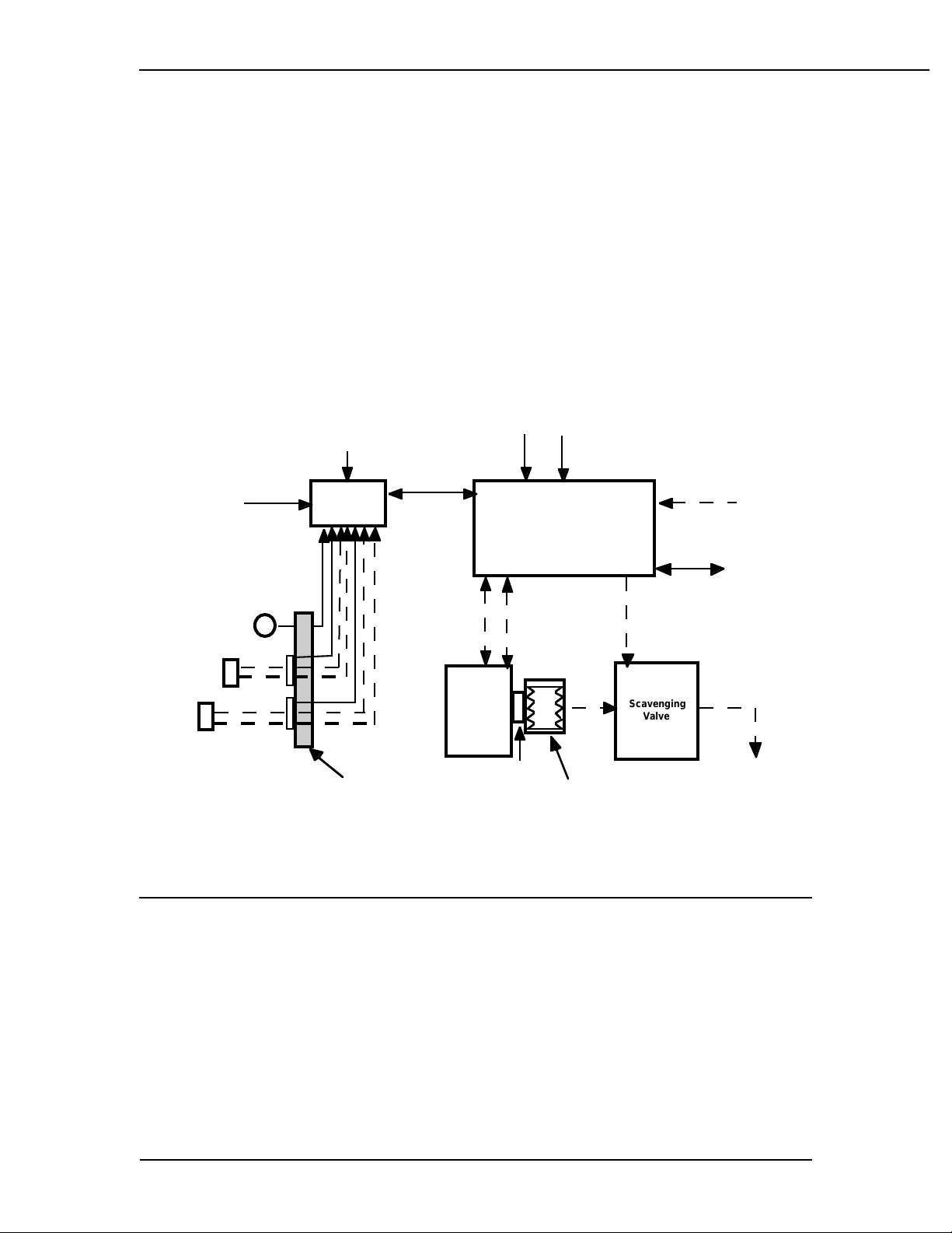
The 7900 Ventilator is a microprocessor based, electronically controlled, pneumatically driven ventilator with a built in monitoring system for inspired oxygen, airway
pressure and exhaled volume. The 7900 is a "Closed Loop Control Ventilator."
Sensors in the breathing circuit are used to control and monitor patient ventilation
as well as measure inspired oxygen concentration. This allows for compensation
of compression losses, fresh gas contribution, valve and regulator drift and any
small leakage in the breathing absorber, bellows and system. User settings and
microprocessor calculations control breathing patterns. The 7900 has a user-selectable Heliox mode to allow gas composition compensation when Heliox gas is
used.
User Inputs
O2 Flush
O2 Pressure
SIB
Board
SIB
able
9 Soft keys,
1 knob
entilator
Control
Module
C Power
5 - 100 psi Suppy
Optional
ommunications
Cable
R
A
Gas
Scavenging
Valve
o Vacuum
xhaust Gas
System
low Sensors
ensor
SIB
Interface
Panel
Absorber
GMS
MAS
Mk5
bsorber
anifold
Bellows
Figure 2-1
7900 Ventilator - Excel SE and Modulus SE Anesthesia System Interface.
User interface settings are stored in non-volatile memory. The user may change
settings with a simple and secure setting sequence. A bellows contains breathing
gasses to be delivered to the patient
Positive End Expiratory Pressure (PEEP) is regulated electronically. Positive pressure is maintained in the breathing system so that any leakage occuring is compensated for by the ventilator to maintain PEEP.
An RS-232 serial digital communications port connects to and communicates with
external devices.
1503-0151-000 3/27/97 2-1
2/Theory of Operation
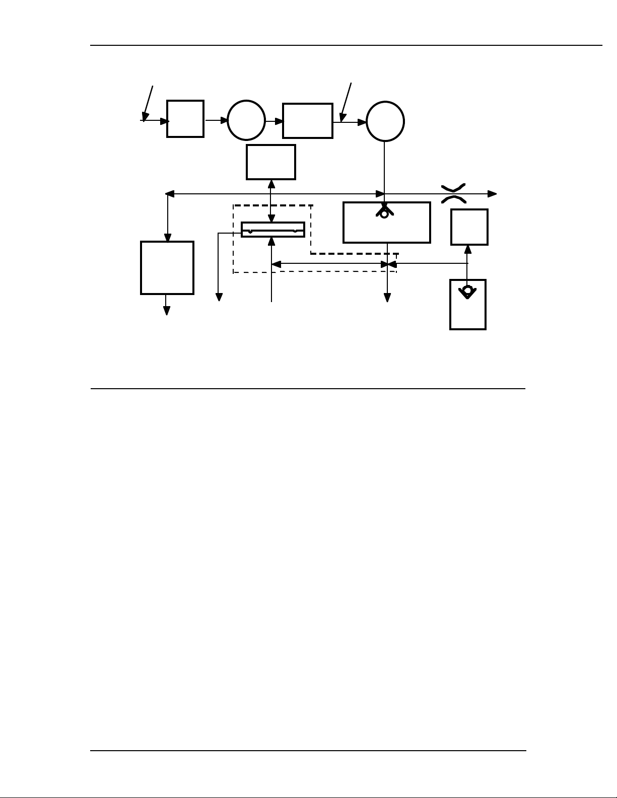
35 - 100 psi
Supply
Supply
Gas
Hose
Mechanical
Overpressure
Bleed Off
(MOBO)
Ambient
Inlet
Filter
Exhaust
to Scavenging
SystemExhaust to
Gas
Inlet
Valve
(GIV)
Manifold
Pressure
Transducer
Exhalation
Pressure
Regulator
Manifold
Drive Gas Check Valve
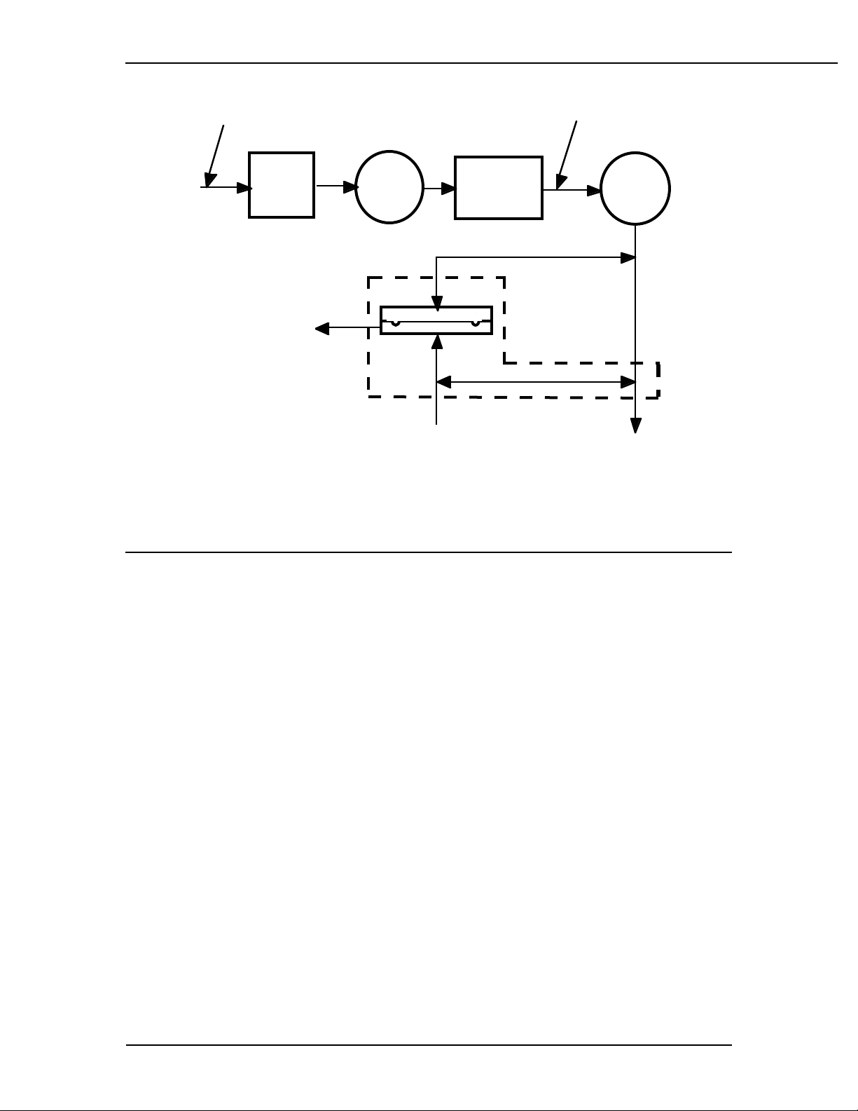
Figure 2-2
7900 Ventilator Operational Block Diagram
25 psi
Flow
Valve
(DGCV)
25 mm port17 mm port
Pressure
Switch
Free
Breathing
Valve
Bleed Exhaust
to Ambient
Some 7900 Ventilator Features
• No secondary regulator or exhalation solenoids
• An exhalation valve that modulates flow in the pressure mode rather than being just on and off
• Pressure and volume mode selectable by the operator
• All pneumatic components are mounted on a single manifold.
• Each component is individually accessible from above or below the
manifold
• There are no threaded connections to the subassemblies
• Drive gas and bellows pressure relief valve gases are combined
and pass through the ventilator exhalation valve.
• Exhalation valve block is autoclavable
• Scavenging line runs from the ventilator to the Anesthesia Gas
Scavenging Receiver (AGSR) which scavenges both drive gas and
gas released by the bellows pressure relief valve.
• Operates in a "Closed-Loop" configuration during both volume and
pressure modes of operation
• Easier to service, fewer components and improved performance.
2-2 1503-0151-000 3/27/97
2/Theory of Operation
Safety Features
• Dual redundant airway over pressure protection, linked to the Pmax
setting
• Volume over-delivery limits and protection
• Ohmeda proprietary hose connections - fixed manifolds to reduce
leaks
• Uses proven mechanical components
• 10 VA - Oxygen compartment separation
• 500 psi burst protection
2.2 Mechanical
35 - 100 psi
Supply inlet
Inlet
Filter
Supply
Outlet
Gas
Hose
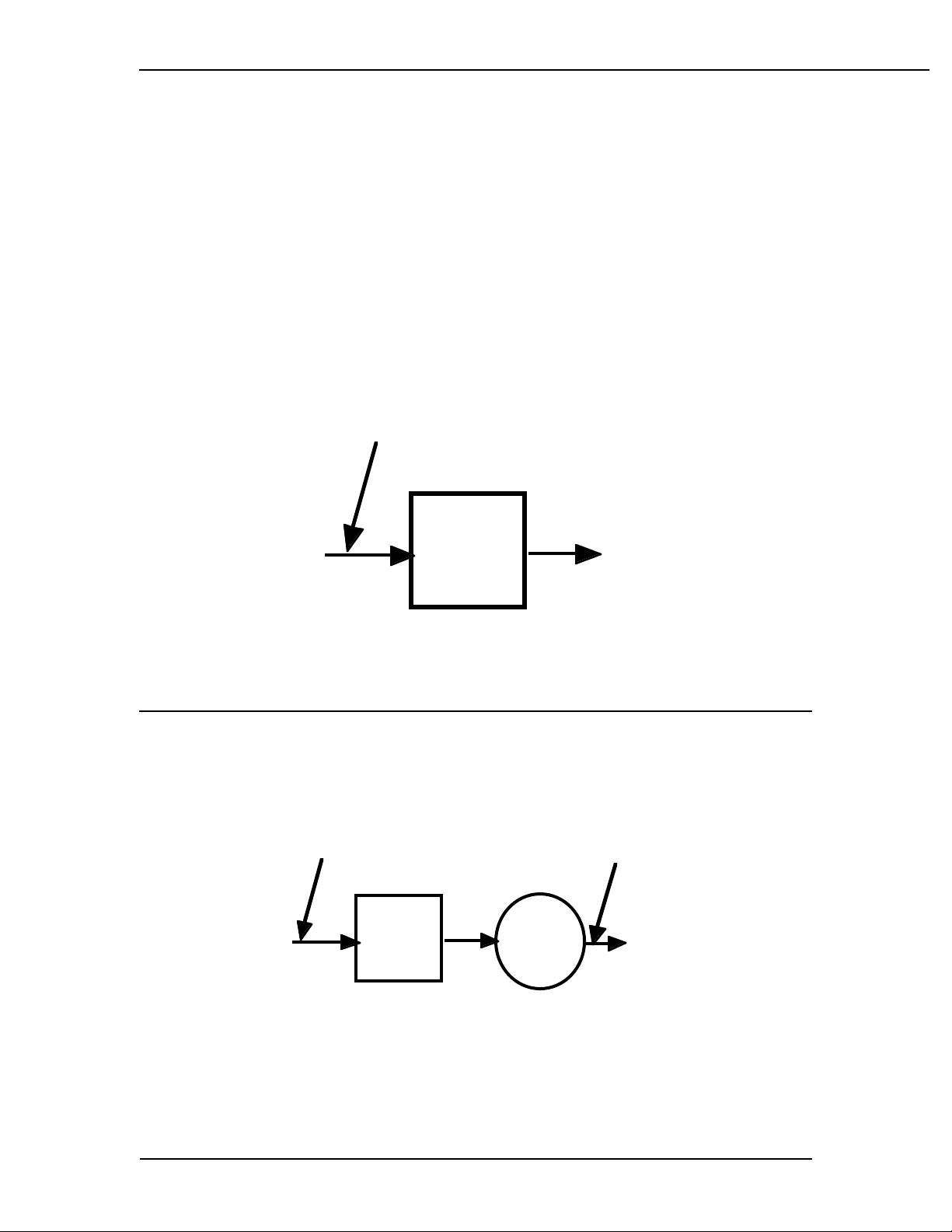
Figure 2-3
Supply gas inlet, filtered
Supply Gas which can be powered from O2 or Air, is supplied from the anesthesia
machine at a pressure of 241 to 690 kPa (35 to 100 psi). This supply gas is filtered
through the 5 micron filter and water trap to further eliminate any minute particles
of contaminate. The filter does not significantly reduce the output pressure on the
downstream side of the filter.
35 - 100 psi
Outlet
Supply
Gas
Hose
35 - 100 psi
Supply inlet
Inlet
Filter
Gas
Inlet
Valve
(GIV)
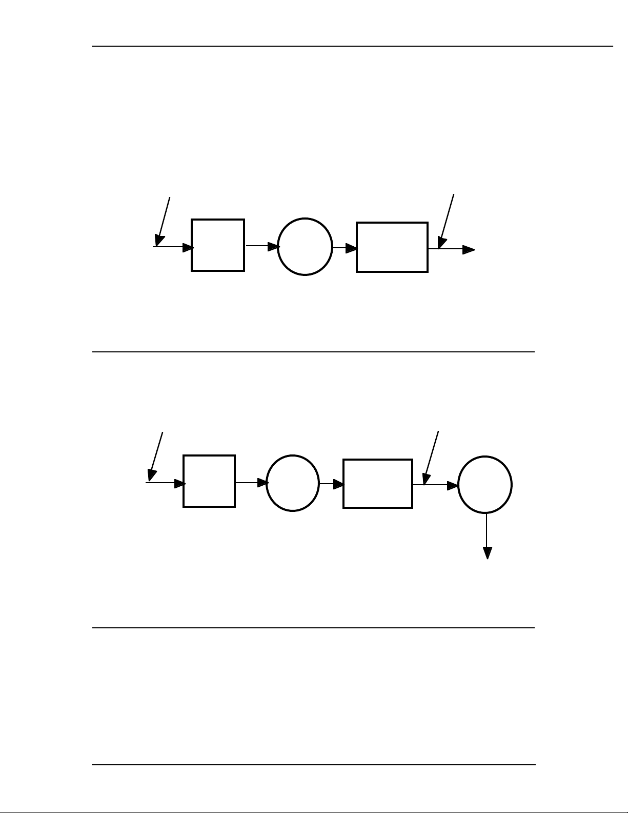
Figure 2-4
Gas Inlet Valve
1503-0151-000 3/27/97 2-3
P
G
Fl
P
G
2/Theory of Operation
During normal operation the GIV (Gas Inlet Valve) is open to allow the supply gas
to flow to the ventilator manifold. This valve provides a shut off of the supply gas
to the ventilator when the ventilator is not in use. The GIV also shuts off supply
gas to the ventilator under failure conditions as the microprocessor or over-pressure switch demands. The output from the GIV remains at the filtered supply gas
pressure.
Supply
Gas
Hose
5 - 100 psi
Supply inlet
Inlet
Filter
Figure 2-5
Non-Relieving Pressure Regulator
as
Inlet
Valve
(GIV)
ressure
Regulator
5 psi
utlet
The pressure regulator is a Non-relieving Pressure Regulator which regulates
the high pressure filtered supply gas, oxygen or medical air, down to 172 kPa
(25 psi).
Supply
Gas
Hose
35 - 100 psi
Supply inlet
Inlet
Filter
as
Inlet
Valve
(GIV)
ressure
Regulator
25 psi
ow
Valve
Figure 2-6
Flow Control Valve
The Flow Control Valve is controlled by the microcontroller. Signals are sent to the
Flow Control valve which correspond to the generated flow requirements called for
by ventilator settings and sensor signals. The Flow Control Valve modulates the
incoming 25 psi drive gases to a variable output from 0 to 120 liters per minute at
pressures nominally ranging from minus 10 to plus 100 cmH
2-4 1503-0151-000 3/27/97
- 120 Lpm
O.
2
V
2/Theory of Operation
Supply
Gas
Hose
5 - 100 psi
Supply inlet
nlet
ilter
Exhaust
to Scavenging
Valve (AGSR)
30 mm Port
Figure 2-7
Exhalation Manifold
Gas
Inlet
Valve
(GIV)
Exhalation Manifold
17 mm Port
Bellows Return
Gas
Pressure
Regulator
5 psi
Flow
alve
anifold Pressure
25 mm Port
Bellows Drive
Gas
1503-0151-000 3/27/97 2-5
A
Fl
P
Inl
17
t
Exhalati
ld
2/Theory of Operation
The autoclavable Exhalation Valve Manifold contains an elastomeric diaphragm
used in association with the flow valve to control the pressures within the breathing
circuit. The manifold contains ports for the bellows drive gas (25 mm), the bellows
return gas (17 mm) and the AGSS (Anesthesia Gas Scavenging System) (30 mm).
Pilot control of the exhalation valve is accomplished through pneumatic connections internal to the 7900 ventilator main pneumatic manifold. The valve is normally open, requiring approximately 2 cmH
circuit.
O of pilot pressure to seal the breathing
2
Supply
Gas
Hose
35 - 100 psi
Supply inlet
et
Filter
Exhaust
to Scavenging
System
as
nlet
alve
GIV)
on
mm por
ressure
Regulator
anifo
25 psi
ow
Valve
Drive Gas Check Valve
(DGCV)
25 mm port
Bleed to
mbient
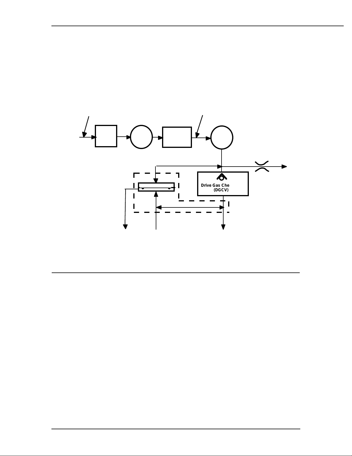
Figure 2-8
Drive Gas Check Valve
In order to generate the required pilot pressure for sealing the exhalation valve during inspiratory periods, a DGCV (Drive Gas Check Valve) is used downstream of
the exhalation valve pilot connection. This valve is biased shut using an integral
weight so as to generate approximately 3.5 cmH
O of bias pressure prior to allow-
2
ing flow downstream to the breathing circuit. During periods of operation when the
ventilator is exhausting flow from the breathing circuit, the DGCV allows the exhalation valve pilot pressure to be de-coupled from the circuit pressure, thus allowing
the exhalation valve to open and flow to exhaust and the scavenging system.
2-6 1503-0151-000 3/27/97
l
t
t
2/Theory of Operation
35 - 100 psi
Supply inlet
upply
Gas
Hose
Mechanica
Overpressure
Bleed Off
(MOBO)
Exhaust to
Ambient
Inlet
Filter
Exhaust
to Scavenging
System
Gas
Inlet
Valve
(GIV)
Manifold
Pressure
Transducer
xhalation Manifold
17 mm por
ressure
egulator
5 psi
Flow
Valve
Drive Gas Check Valve
(DGCV)
25 mm por
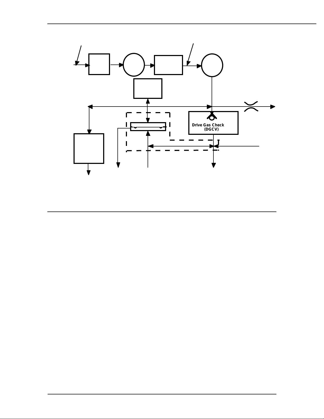
Figure 2-9
MOBO (Mechanical Over pressure Bleed Off)
The Mechanical Over pressure Bleed Off Valve is a mechanical valve operating
even if there is no electrical power. The MOBO has two functions. First, it serves
as a third level of redundancy to the ventilator's pressure limit control functions,
providing pressure relief at approximately 110 cmH
O. Second, the MOBO serves
2
as a backup in the event of a complete blockage of the exhalation valve system,
relieving circuit pressure at approximately 30 cmH
O under such failure conditions.
2
1503-0151-000 3/27/97 2-7
S
1
2/Theory of Operation
35 - 100 psi
Supply
upply
Gas
Hose
Mechanical
Overpressure
Bleed Off
(MOBO)
Ambient
5 psi
Inlet
Filter
Exhaust
o Scavenging
SystemExhaust to
Gas
Inlet
Valve
(GIV)
Manifold
Pressure
Transducer
Exhaltion
Manifold
7 mm port
ressure
egulator
Flow
Valve
rive Gas Check Valve
(DGCV)
25 mm port
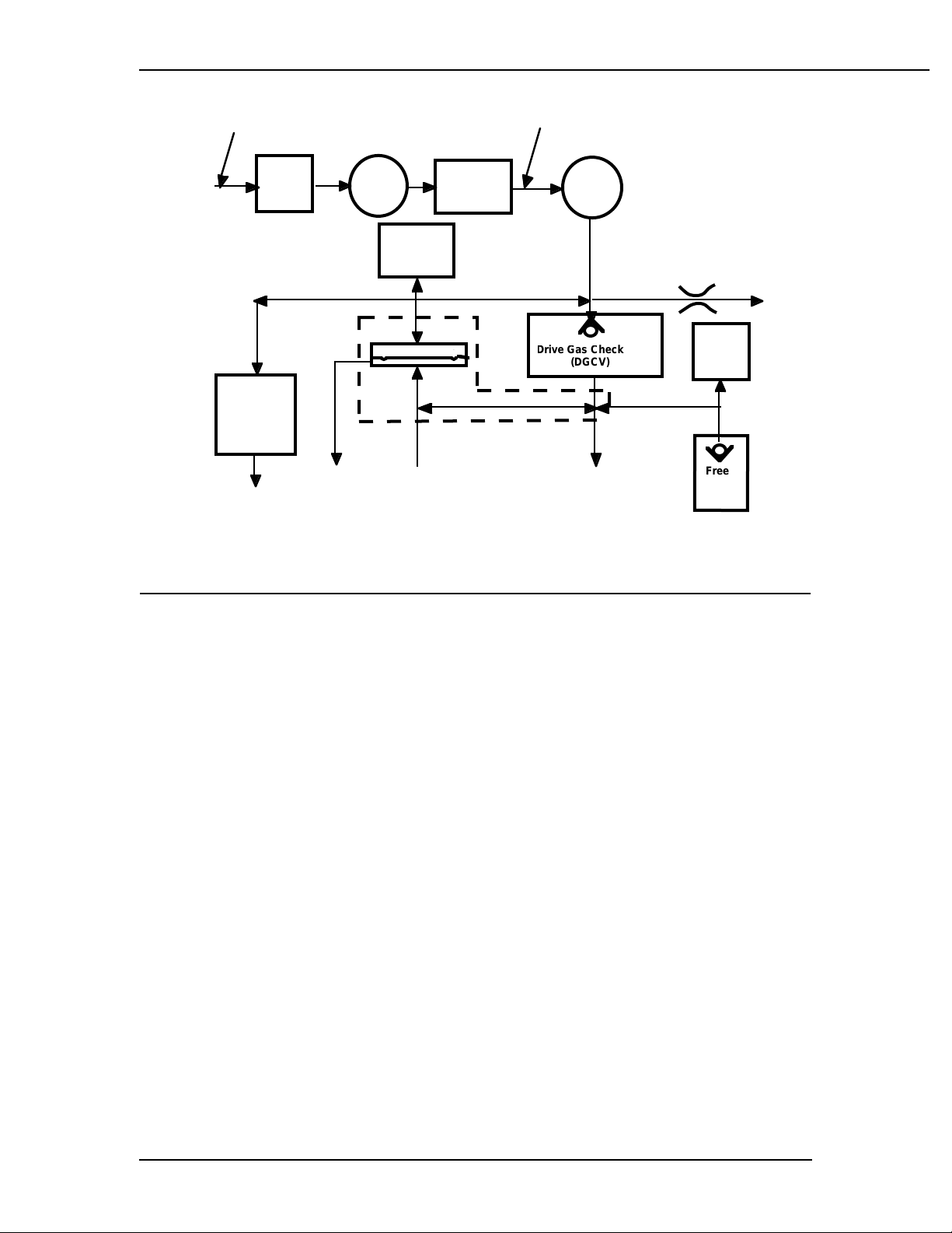
Figure 2-10
Bleed Resistor, Pressure Switch and Free Breathing Valve
Pressure
Switch
Free
Breathing
Valve
leed Exhaust
to Ambient
The Bleed Resistor is, by design, a "controlled leak" from 0 to 10 L/min. in re-
sponse to circuit pressures from 0 to 100 cmH
O
The small amount of pneumatic
.
2
flow exhausting through the bleed resistor allows for control of the exhalation
valve's pilot pressure by modulation of the valve output. The bleed resistor exhausts only clean drive gas and should not be connected to a waste gas scavenging circuit. The output is directed away from the electrical components to ensure
that systems using oxygen drive gas meet the 10VA requirement for oxygen enrichment.
The Pressure Switch is an electrical limit which automatically shuts off the GIV
(Gas Inlet Valve) and flow valve if the pressure reaches a level of approximately
O
When either or both of these valves is shut, the pilot pressure to the
104 cmH
.
2
exhalation valve falls rapidly as the flow discharges out the bleed resistor. As the
pilot pressure is relieved, the exhalation valve opens allowing circuit pressure to be
relieved.
The Free Breathing Valve , also shown in figure 2-10, allows the patient to take a
spontaneous breath. The ventilator is programmed to supply a certain number of
breaths per minute to the patient. If, in between one of these programmed cycles,
the patient requires a breath (spontaneous) the free breathing valve allows the patient to inhale ambient air spontaneously.
2-8 1503-0151-000 3/27/97
2/Theory of Operation
2.3. Electrical
The 7900 Ventilator consists of the following electronic/electrical subassemblies or
modules:
• Microcontroller Printed Circuit Board
• Front Panel Assembly
• Power Supply and External I/O Interface Board
• Sealed Lead Acid Battery
• Power Entry Module and Toroid
• Sensor interface board
The specific function of each of these items is described in subsequent sections.
Figure 2-11
Electronic functional block diagram
1503-0151-000 3/27/97 2-9

2/Theory of Operation
Power Supply Assembly
The power supply board encompasses two functional blocks: power supply and
external interface.
Power Supply
The power supply is divided into three stages,
• ac to dc Conversion
• dc Step-down Regulator and Battery Charger
• Multiple Output dc to dc Converter
Functional Specifications
• Autoranging input 85-132 and 190-270 Vac, 47-63 Hz, 54.5 VA.
• Output 5V for digital circuit, 5.5V for electromechanical actuators,
14.5 V for EL display and ± 15V for analog circuits.
• Approval to UL-544, CSA, VDE, IEC-601 and other applicable medical product standards.
• Leakage current under 300 micro Amps @ 132 Vac, 60 Hz.
• Output short-circuit, over-voltage protection, with automatic recovery after removal of fault.
• Battery under-voltage disconnect function protects charging bad
cell.
• Battery under-voltage cutoff function protects over-discharging.
• 30 minute battery backup operation under normal application.
Power Requirements
• Maximum input requirement: 54.5 VA ac
• Maximum output capacity: 26.7 W dc
Heat generation
The maximum heat generated from the power supply is 27.8 Watts.
ac to dc Conversion
Input Voltage ranges from 85 to 132 and 190 Vac to 270 Vac, 47 to 63 Hz enters
the unit via power entry module with a medical grade line filter. This filtered output
is converted to dc voltage via a toroidal isolation transformer and bridge rectifier.
2-10 1503-0151-000 3/27/97

2/Theory of Operation
Power Entry Module
• Type Line Filter with ac Connector & 5 X 20
• Maximum leakage current < 5 µ A @ 250V/50Hz
• Fuses 2A 250V. Slow blowing 5X20 mm
• Approvals UL 1283, CSA C22.2/8, VDE 0565 &
Toroid
• Type High efficiency toroid
• Power capacity 54.5 VA
• Voltage rating 85-270Vac / 14-45 Vac
• Leakage current 25 µ A Max.
• Power efficiency 85% - 90% @ 115Vac 60Hz, 60VA
• Safety screen thickness 0.005" Cu.
• Isolation hipot voltage 4KV.
• Thermal fuse
• Dimension 115 mm diameter x 58 mm thickness
• Weight 4.8 lb
• Mounting method Epoxy center hole 0.5 in. ID.
mm Fuse holder
EN 60320
Thermik S01 110
o
C
ac to dc rectifier
• Topology Full wave bridge/voltage doubling with
auto/voltage adapter
• Rectifier type GBU8D 8A, 200V
• Peak current surge 300A (JEDEC Method).
• Power efficiency 92% - 95%
• Output filter capacitor 2 x 5600uF 63WVdc, 3.93A allowable
ripple current at 120 Hz, 85
load life at 85
• Output ripple voltage < 2.5 Vp-p
• dc output voltage range 24 - 62 Vdc
• Auto-voltage adapting threshold 140/155 Vac
o
C 50V 3.93A 120 Hz rip
o
C, 2000 hr.
1503-0151-000 3/27/97 2-11

2/Theory of Operation
ac Power-On Indicato r
• Type LED
• Color Green
• LED drive current 15mA.
• Location Display Board
ac Step-Down Regulator and Battery Charger
The dc step-down regulator takes the output from ac/dc conversion stage (24-62
Vdc) and converts it to 16.6 Vdc. The battery charge circuit charges the sealed lead
acid battery anytime ac power is supplied.
A Schottky Diode provides uninterrupted-power-supply (UPS) function during acpowered to battery powered transitions. When ac power is interrupted, the switchover between ac and Battery is automatic. When ac power is off, this diode also
works as a reverse blocking device preventing the battery from being drained by
the regulator circuitry.
Synchronous step-down regulator
• Power efficiency 80 - 85%
• Input voltage range 24 - 62 Vdc
• Switching Controller MAX797
• Switch devices 100V 19-28A, 0.20 / 0.07 ohm. MOSFETMTW 4510E / IRF540.
• Output Ripple Less than 200mV peak to peak
• dc output voltage 16.6 V
Lead acid battery charge controller
The battery charge circuit charges the sealed lead acid battery anytime ac power
is supplied. This circuit is based on the Unitrode UC3906 charger controller which
monitors and controls both the charging voltage and current through three separate charge states:
• a high current bulk-charge state,
• a controlled over-charge,
and
• a precision float-charge.
This sequence maximizes battery capacity and life while minimizing charge time.
Switch over circuitry detects the presence or loss of ac supplied power and provide
an automatic and transparent transition to AC or battery power.
2-12 1503-0151-000 3/27/97
 Loading...