

Page 1
e
5120
Oxygen
Monitor
Operation
and
Maintenance
Manual
BOC
Health
Care
Page 2
USER
RESPONSIBILITY
This
contained
inserts,
accordance
checked
that
should
become
request
Service
repaired
by
altered
Department.
responsibility
faulty
other
TRACEABILITY:
this
registration
Ohmeda.
6050-0000-134.
Product
periodically.
are
be
necessary,
for
Center.
Ohmeda
without
maintenance,
than
equipment.
when
broken,
other
If
will
in
this
assembled,
with
replaced
service
than
and
by
The
for
Ohmeda.
Federal
card
additional
perform
operating
the
instructions
missing,
immediately.
Ohmeda
advice
This
in
Ohmeda
the
prior
user
any
improper
Please
included
in
operated,
A
defective
plainly
recommends
Product
accordance
trained
written
of
this
malfunction
law
fill
cards
conformity
manual
be
made
or
any
personnel.
Product
repair,
in
the
out
with
this
are
and
accompanying
maintained
provided.
Product
worn,
Should
that
to
the
of
its
with
approval
U.S.A.
the
required,
written
shall
which
damage,
self-addressed
product
with
distorted
such
the
and
This
should
repair
a
telephonic
nearest
parts
The
of
Ohmeda's
have
results
or
requires
and
order
description
labels
repaired
Product
not
be
or
contaminated
or
replacement
or
Ohmeda
should
instructions
Product
the
from
alteration
traceability
return
Stock
not
must
Safety
sole
improper
traceability
Number
thereof
and/or
in
must
used.
written
Regional
be
provided
not
by
it
to
be
Parts
be
use,
anyone
of
CAUTION:
sale
by
Federal
or
on
the
law
order
in
U.S.A.
a
of
and
licensed
Canada
medical
restricts
practitioner.
this
device
to
Page 3
Addendum
Operation
to
0178-1757-000
For
Contract
the
and
Number
5120
Maintenance
(04
Oxygen
87
RB)
DLA120-87-C-4281
Monitor
Manual
Number
NOTE:
should
sample
NOTE:
(every
tion
NOTE:
monitor
105D
in
NOTE:
Storage
be
size.
Perform
4
3.
Storage
for
Section
The
enviroment
B).
NOTE:
eration
dry
To
enviroment
performed
months).
sensors
unit
3.
5120
with
maximize
is
not
Inspection
at
Follow
the
preventative
Follow
Inspection
should
sample
Oxygen
temperatures
the
available,
at:
Temperature:
Requirements
30
month
Preoperative
the
Requirements
be
performed
size.
Monitor
oxvgen
the
Humidity:
intervals.
Checkout
maintenance
Preoperative
-
at
Follow
not
monitor
sensor should
should
to
the
exceed
sensor
-20'C
55%
+/-
-
Inspection
Use
for
units
Checkout
Inspection
12
month
Preoperative
be
stored
-28'C
s
be
(68
F)
+/-.2°C
5%
of
MIL-STD
Procedure
in
Procedure
of
intervals.
Checkout
to
+54°C
shelf
stored
life,
3
units
105D
in
service
units
in
a
(-20'F
in
a
in
for
Section
quarterly
with
Use
Procedure
clean
when
clean
storage
in
oxygen
MIL-STD
to
refrig-
unit
3.
Sec-
dry
130
and
Addendum
No.
0178-1759-000
(01
88)
Page 4
LIST
OF
ILLUSTRATIONS
Figure
Figure
Figure
Figure
Figure
Figure
Figure
Figure
Figure
Figure
Fioure
Figure
Figure
Figure
Figure
LIST
Chart
Chart
LIST
Table
OF
OF
の
Ohmeda:
Standard
oO
Optional
5120
me
Probe
Universal
の
aa
Oxygen
Oxygen
oo
Oxygen
10.
Battery
115
Rear
12:
Replacing
134
Battery
14.
Replacement
15.
Rear
CHARTS
1.
Operation:
2.
Troubleshooting
TABLES
ES
Remote
5120,
Accessories.
Accessories
Oxygen
Holder
Monitor,
Monitor,
Monitor,
Compartment
View
Replacement
View
Alarm
Oxygen
Monitor
Mounting
ее
Sensor
Parts
ee
Summarv
Guide:
Pulse
Monitor
Block
|.
»
Clamp
Front
Front
Front
cartridge
ee
of
Codes
.
so
.
.
Diagram
ο
View
View
View
ev
s
e
ae me
e
des
Displays,
i
ον
2.
το
-555
ενος
=
a
sl
ο
οσο
ο
.
.
. .
(continued)
(continued)
be
çi
еее
ее
es
e
Alarms
Sad
eo:
ее:
ο
e
ο
ο
ee
and
ος τα
e
ο»
ее
>
.
ος
a
o
Page 5
TABLE
OF
CONTENTS
PRECAUTIONS
Introduction
System
1.0
GENERAL
151
Description
1.2
'ACCessorlesı
1.3
Theory
1.4
Specifications
+0
SETUP
Del
Setup.
2.2
Mounting
2.3
Controls
2.4
Alarms
255
calibrations
3.0
OPERATION
3.1
Preoperative
3%
2"
Operation
4.0
OPERATOR
4.1
Cleaning
(Warnings
..
Installation
INFORMATION
of
Operation.
AND
CALIBRATION
se
e
and
оо
<...
2
MAINTENANCE
and
and
Cautions)
. .
(Modulus
. .
“iile,
5...
e ο ο ο e
・
3
sc
ooo
. . . . .
ο
ος
λος
Components
oie
Checkout
Sterilization
desto
wipe
We
S
AO
II
Anesthesia
aile
οσο
ο ο
. . .
e
e e
ae
Procedure
e e
ko
Maleta
«de
cite
3
.
.
.
ο
System)
dd
ロロ
5.0
SERVICE
5.1
5.2
5.3
5.4
APPENDIX
APPENDIX
WARRANTY
PROCEDURES
Repair
Policy
Troubleshooting
Parts
Replacement
Replacement
A - Output
B - System
さる We
로 6 고
and
Procedure
Guide
Procedures
Parts
ον ος ο κος
List
Connector
Test Mode
....
da
. . .
. .
ον
ο ο ες
oe
oii
39
.
39
40
43
o
48
49
.
52
53
Operation
and
Maintenance
Manual
Page
i
Page 6
PRECAUTIONS
A
WARNINGS:
e
Connect
the
that
monitor.
If
the
Checkout
corrected.
A
When
moisture
Use
immerse
or
Do
not gas
Do
not
Following
(front
only
output
is
lower
See
monitor
Procedure,
caurions:
in
use,
build-up
the
recommended
autoclave
sterilization
half
quarantine
absorbed
recommendations
by
a
high
connector.
than
page
fails
Pages
See
the
sensor
monitor.
the
sterilize
the
only)
parts
the
to
material.
for
impedance
the
24,
to
do
29
its
on
cleaning
the
monitor.
of
the
allow
procedure
Improper
corresponding
respond
not use
36.
and
should
sensing
solution
Page
See
monitor.
See
with
tee
ethylene
manifold,
dissipation
Follow
and
device
loading
as
it
until
always
surface.
36.
See
Page
sterilizer
aeration
(at
least
will
value
described
the
be
pointing
sparingly;
Page
36.
oxide
or of
of
residual
10
result
displayed
in
the
malfunction
Page
See
do
36.
of
the
the
sensor
manufacturer's
period.
K
ohms)
in
an
output
by
the
Preoperative
has
down
31.
not
probe
to
saturate
housing
cartridge,
ethylene
See
Page
to
pin
oxygen
been
reduce
oxide
37.
5
of
voltage
gas
©
Only
should
Detailed
service
knowledge,
competent
trained
After
the
the
replacing
Preoperative
monitor
stabilize
After
fresh
Procedure
properly.
Page
ii
individuals
attempt
information
manual solely
by
the
in
See
to
tools
Ohmeda.
the
is
working
sensor;
batteries
Section
Page
and
Checkout
service
for
for
test
See
sensor
refer
are
3.1
46.
trained
it.
more
the
equipment,
Page
properly.
39.
cartridge
Procedure
to
installed,
to
verify
in
See
Page
extensive
convenience
and
or
in
Allow
the
NOTE
perform
that
the
39.
repairs
for
the
Section
at
on
the
repair
of
users
service
sensor
least
page
the
monitor
of
this
is
included
having
assembly,
3.1
to
five
28.
See
Preoperative
is
equipment
in
the
proper
representatives
perform
verify
minutes
Page
that
to
43.
Checkout
working
5120
Oxygen
Monitor
6
Page 7
INTRODUCTION
This
manual
prepare,
Read
through
attention
manual
Read
the
it
The
life
statement
to
Keep
concerning
case
the
user
lists
oxygen
affected
realize
this
of
operate,
to
and
are
User
to
Ohmeda's
sensor
(on
maximum
manual
the
failure,
contains
and
the
entire manual
the
Warnings
summarized
Responsibility
maintain
responsibility
cartridge
by
several
page
5)
service
available
monitor's
its
information
maintain
and
in
a
safe
and
is
factors.
about
proper
life.
for
operation,
repair.
that
the
Ohmeda
before
Cautions
the
PRECAUTIONS
statement;
accurate
in
case
a
consumable
Read
handling
answering
its
will
guide
5120
using
the
which
it
lists
instrument.
of
a
item
the
Sensor
and
questions
maintenance,
you
Oxygen
monitor.
appear
section.
what
functional
with
Life
storage
which
to
properly
Monitor.
Pay
throughout
is
expected
Read
the
defect.
a
limited
Expectancy
of
the
may
in
or
special
this
of
Warranty;
service
sensor
arise
System
The
carried
size
such
except
footnotes,
stand-alone
Consult
Manual
the
monitor
Installation
5120
Oxygen
from
makes
as
the
for
the
for
Monitor
place
it
an
Modulus
a
few
the
or as
to
ideal
considerations
operation
a
Modulus
information
and the
(Modulus
is
place
module
II
Anesthesia
of
system
II
Anesthesia
regarding
rest
of
II
Anesthesia
a
stand-alone
as
required.
for
explained
the
monitor
unit.
the
system.
use
in a larger
System.
is
System
the
interconnection
System)
unit
However,
which
In
either
in
referenced
identical
Operation
can
its
compact
system
case,
as
and
between
be
a
Maintenance
Operation
and
Maintenance
Manual
Page
1
Page 8
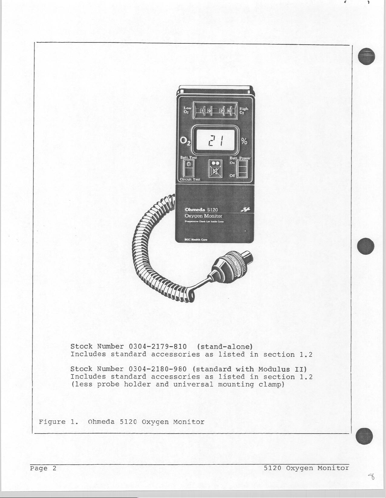
Stock
Includes
Stock
Includes
(less
Number
standard
Number
standard
probe
0304-2179-810
accessories
0304-2180-980
accessories
holder
and
Oxygen
(stand-alone)
(standard
universal
Monitor
as
listed
as
listed
mounting
with
in
Modulus
in
clamp)
section
section
1.2
II)
1.2
Figure
Page
2
1.
Ohmeda
5120
Oxygen
Monitor
5120
Oxygen
Monitor
a
も
Page 9
1.0
GENERAL
INFORMATION
This
illustrates
of
1.1
The 5120
throughout
nursery,
The
(LCD)
100
easy
section
operation
Description
Oxygen
or
5120
Oxygen
that
percent.
viewing.
describes
the
(1.3),
the
hospital:
wherever
indicates
The
Additional
- A switch-operated
- A digital
set
points.
Setting
tones
does
alarm
switch
the
and
not
accept
whenever
regardless
the
accessories
and
Monitor
a
measurement
Monitor
oxygen
digits
backlight
to
select
Low
02
a
continuous
low
the
of
how
general
supplied
lists
(refer
in
anesthesia,
features
concentrations
are
large
features
High
alarm
visual
alarm
displayed
far
below
features
detailed
to
Figure
of
a
LIQUID
(1.3
include:
for
viewing
02
limit
limits
02
18%
with
it
specifications
1
on
in
respiratory
oxygen
CRYSTAL
from
cm,
in
and
Low
below
indicator
18%
below
reading
the
Low
of
the
monitor
(1.2),
page
concentration
2)
digital
zero
0.5
inches,
subdued
O2
alarm
results
(vellow).
18%.
is
02
The
below
alarm
includes
(1.4).
can
therapy,
to
high)
light(*).
limit
in
The
monitor
18%
limit
(1.1),
a
be
used
is
required.
DISPLAY
for
three
monitor
will
02
is
theory
in
the
beep
set.
Setting
High
procedures.
-
Visual
concentration.
concentration
For
silenced
than
Alarm
duration
remain
The
(*)
external
General
the
O2
alarms,
and
audible
a
Low
for
Low
02,
Silence
of
active
backlight
source;
Information
High
alarms
The
is
less
O2
alarm
approximately
the
switch,
the
throughout
always
is
example,
for
02
a
feature
alarms
than
condition,
audible
alarm
alarm
to
warn
respond
or
alarm
and
condition.
any
when
on
a
limit
useful
of
greater
the
30
seconds.
will
alarm
the
Modulus
switch
during
a
low
whenever
than
audible
mav
he
remain
The
condition.
monitor
II
to
"00"
100%
or
a
the
the
selected
alarm
For
conditions
silenced
silenced
visual
is
Anesthesia
disables
oxygen
high
displayed
oxygen
can
with
for the
indicators
powered
System.
the
flush
oxygen
limits.
be
other
the
an
by
Page
3
Page 10
-
-
-
A
that
A
sensor
A
sensor
assembly
extends
long-life
assembly
The
sensor
compensation.
when
used
humidity
exposed
anesthesia
non-condensing).
hinged,
front
to
approximately
oxygen
without
includes
to
when
cover
which
attaches
cartridge
tools.
an
The
sensor's
carbon
gases.
monitoring
that
6
feet.
which
internal
accuracy
dioxide,
The
sensor
a
humidified
opens
to
the
can
thermistor
nitrous
for
easy
monitor
be
is
is
also
easily
not
oxide
insensitive
gas
stream
access
with
a
replaced
for
temperature
noticeably
or
other
(95%
to
coiled
in
affected
normally
to
R.H.
cable
the
&
a
--
the
--
and,
--
-
Two
modes
a
--
and
--
which,
life
-
useful
- A front
a
sensor
(88
to
The
displayed
are
- A modular
the
following
Preoperative
calibration
replacement,
for
for
testing
test
as
(LOW.
level,
test
applicable,
BATT),
switch
manual
a
panel
signal
102
%).
circuit
test
messages,
functional.
connector
for
Checklist,
control,
the
initiated
performed
‘or,
halts
(CIRCUIT
simulating
verifies
and
(Output)
remote
batteries.
the
internal
the
by
automatically
either
the
if
operation
TEST)
a
high
that
the
visual
at
the
monitoring
batteries
operator,
by
indicates
batteries
until
the
which
concentration
the
digital
alarm
back
equipment.
of
(*).
monitor,
the
limited
discharged
are
batteries
remaining
electronically
of
oxygen
display,
indicators
the
monitor
below
are
replaced.
substitutes
the
(LEDs)
provides
battery
a
©
-- an
-- a digital
--
(*)
The
external
Anesthesia
Page
4
analog
an
external
battery
source;
System.
signal
output
alarm
tests
for
See
proportional
signal
silence
are
not
example,
item
indicating
valid
when
3
on
input
if
installed
page
to
for
the
18.
the
an
oxygen
alarm
remote
monitor
in a Modulus
concentration
condition
silence
is
capability.
powered
II
by
Section
an
©
One
\b
Page 11
ATTENTION
SENSOR
LIFE
EXPECTANCY
The
oxygen
time
percent
to
This
approximately
For
one
at
to
life
This
atmosphere
Do
prior
This
which
conditions.
increased
prevent
and,
Placing
refrigerator
should
DO
service
and
while
sensor
example,
year
100%
C02
of
sensor
not
to
sensor
will
thus,
NOT
sensor
oxygen
oxygen.
may
the
puncture
the
unopened
extend
FREEZE.
life
is
conditions,
the
in
service.
will
438,000
it
at
50%
also
sensor.)
STORAGE
is
packaged
to
maximize
or
placing
has
vary
relative
enhance
depending
Reduced
sensor
(Temp.
the
of
this
affected
as
sensor
typically
percent
would
oxygen
(Continuous
shorten
the
a
finite
sensors
shelf-life.
typically
or
shelf-life.
open
sensor
temperatures
humidity
from
its
shelf-life.
6 C +/- 3 C)
high-quality
by
storage
well
the
in
the
shelf-life
drying
in
as
is
exposed
function
hours.
6
months
exposure
expected
an
inert
package
in
on
storage
will
a
the
last
service.
and
help
out
for
for
General
Information
Page
5
\\
Page 12
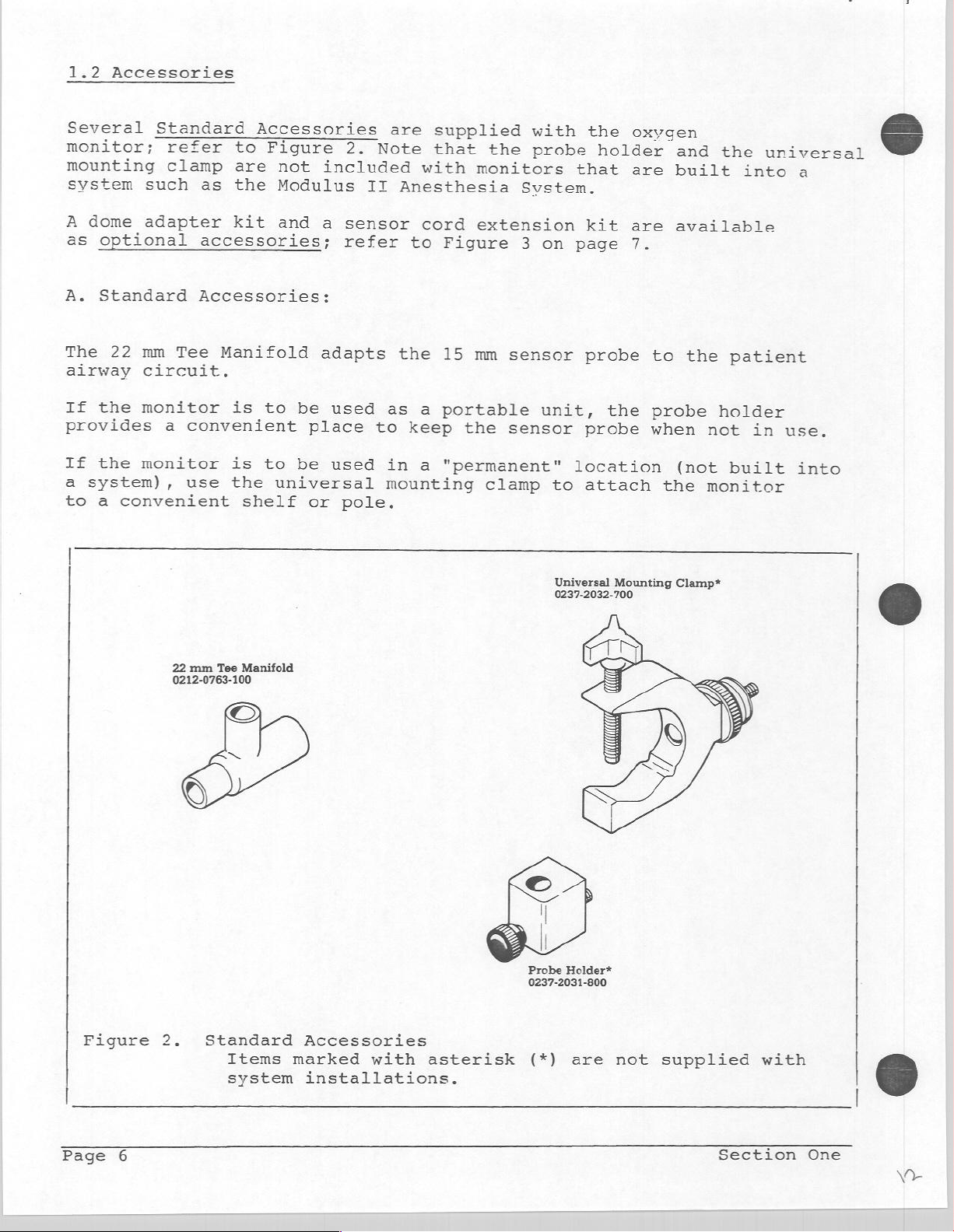
1.2
Accessories
Several
monitor;
mounting
system
A
dome
as
optional
A.
Standard
The
22
airway
If
the
provides
If
the
a
system),
to
a
convenient
Standard
refer
clamp
such
adapter
mm
circuit.
monitor
monitor
as
accessories;
Accessories:
Tee
a
convenient
use
Accessories
to
Figure
are
the
Modulus
kit
Manifold
is
to
is
to
the
universal
shelf
not
and
be
be
2.
included
a
sensor
refer
adapts
used
place
used
or
pole.
are
Note
II
Anesthesia
to
the
as
to
keep
in
mounting
supplied
that
with
cord
a
a
monitors
extension
Figure
15
mm
portable
the
"permanent"
the
sensor
sensor
clamp
with
probe
Svstem.
3
on
unit,
to
the
oxygen
holder
that
page
probe
probe
location
attach
kit
are
are
7.
the
and
built
available
to
the
probe
when
(not
the
the
into
patient
holder
not
in
built
monitor
&
universal
a
use.
into
22
mm
Tee
0212-0763-100
Manifold
©
6)
Universal
0237-2032-700
Probe
Holder*
0237-2031-800
Mounting
Clamp*
©
Figure
Page
2.
6
Standard
Items
system
Accessories
marked
installations.
with
asterisk
(*)
are
not
å
supplied
Section
with
6
|
One
V
と
Page 13
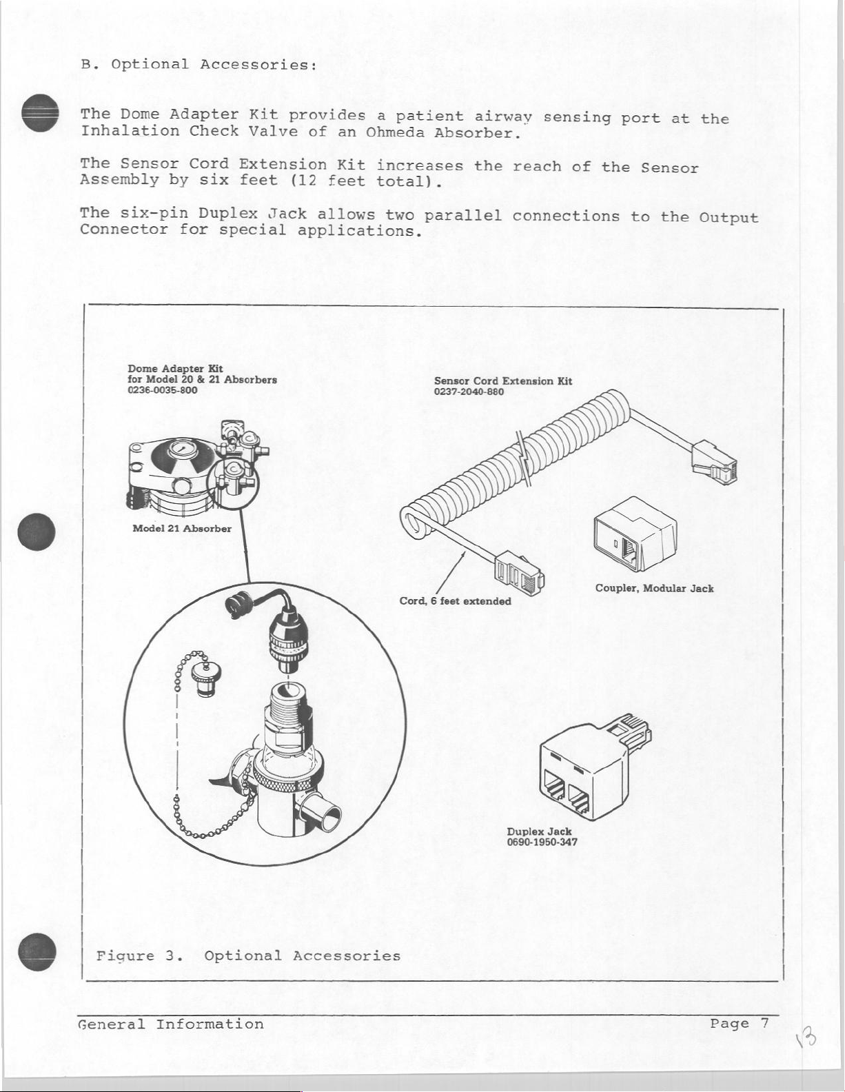
B.
Optional
The
Dome
Inhalation
Accessories:
Adapter
Check
Kit
Valve
provides
of
an
a
patient
Ohmeda
airway
Absorber.
sensing
port
at
the
The
Assembly
The
Connector
Sensor
six-pin
Dome
for
0236-0035-800
by
for
Adapter
Model
Cord
six
Duplex
special
Kit
20 & 21
Extension
feet
Jack
Absorbers
Kit
(12
feet
allows
applications.
increases
total).
two
parallel
Sensor
0237-2040-880
the
reach
connections
Cord
Extension
of
Kit
the
Sensor
to
the
Output
Figure
3.
Optional
Accessories
Cord, 6 feet
extended
È
Duplex
0690-1950-347
Jack
Coupler,
Modular
Jack
General
Information
Page
7
vd
Page 14
1.3
Theory
of
Operation
The
Oxygen
sensor
a
voltage
pressure)
The
sensor
(chemical
current
that
at
diffuses
reaction)
(electrical)
(concentration)
gradually
The
output
consumed
temperature
sensor
The
analyzing
housing
monitor
circuitry
corresponding
to
programmed
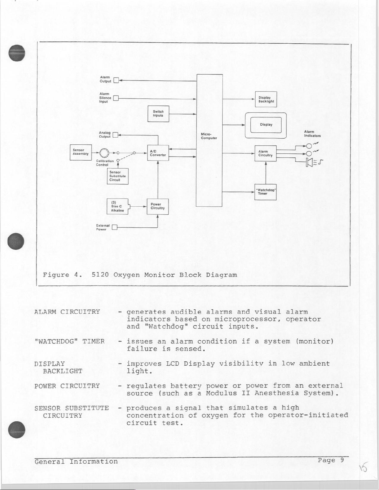
The
block
between
diagram
the
assembly
is
its
cartridge
through
of
voltage
of
the
compensates
assembly
percent
limits
circuit
contains
proportional
detecting
is
an
a
a
base
is
proportional
the
oxygen.
(worn
from
out)
the
monitored
contains
which
oxygen
and
in
Figure
components
an
oxygen
to
surface.
electrochemical
membrane
metal
electrode.
The
by
the
sensor
gas
mixture.
for
temperature
sophisticated
converts
display.
if
required,
4
on
page
described
sensing
the
oxygen
into
to
base
chemical
cartridge
the
sensor
The
appropriate
9
concentration
device
the
cell
The
the
partial
metal
is
A
thermistor
changes,
signal
displayed
details
below.
cartridge
(galvanic
and
resultant
pressure
electrode
process.
affected
processing
signal
alarms
the
relationship
which
oxidizes
oxidation
is
by
in
the
into
a
value
are
produces
(partial
cell).
the
and
is
compared
generated.
6
SENSOR
ASSEMBLY
A/D
CONVERTER
MICROCOMPUTER
DISPLAY
SWITCH
INPUTS
(LCD)
-
produces
oxygen
-
converts
to
-
receives
operator-controlled
circuitry.
-
compares
-
updates
-
generates
concentration.
a
digital
measured
the
indicators
-
generates
converts
-
microprocessor
equivalent.
provide
-
an
microprocessor.
a
signal
the
signal
form
inputs
digital
an
audible
if
an
output
digital
operator
proportional
from
required
from
the
switches
values
Display.
alarm
alarm
signals
information
to
its
interface
the
by
oxygen
to
and
condition
for
visual
to
the
sensor
the
microprocessor.
sensor,
and the
set
limits.
visual
is
remote
from
the
alphanumeric
the
to
monitored
(analog)
the
power
alarm
sensed.
monitoring.
Page
8
Section
One
M
Page 15
나
(7
—
Switch
Inputs
Display
Backlight
Suyu
Alarm
Silence
Sensor
Assembly
Figure
>
scemi,
4.
5120
Analog
Eri
тя
Foa
Calibration
Control
sm
hr.
=
O”
Sensor
Substitute
Circuit
©
b
Size
Alkaline
Oxygen
Converter
Power
ve
Monitor
Ao
Circuitry
Block
a
Miro
Diagram
Alarm
Circuitry
watchdog"
Timer
Alarm
z
~
0
ALARM
"WATCHDOG"
DISPLAY
POWER
SENSOR
General
CIRCUITRY
BACKLIGHT
CIRCUITRY
CIRCUITRY
TIMER
SUBSTITUTE
Information
-
generates
indicators
and
"Watchdog"
=
issues
failure
-
improves
light.
-
regulates
source
produces
-
concentration
circuit
an
is
LCD
(such
a
test.
audible
based
alarm
sensed.
Display
battery
as
signal
of
alarms
on
microprocessor,
circuit
condition
power
a
Modulus
that
oxygen
and
inputs.
if
visibility
or
power
II
simulates
for
the
visual
a
system
Anesthesia
alarm
operator
in
low
from
a
high
operator-initiated
(monitor)
ambient
an
external
System).
Page 16
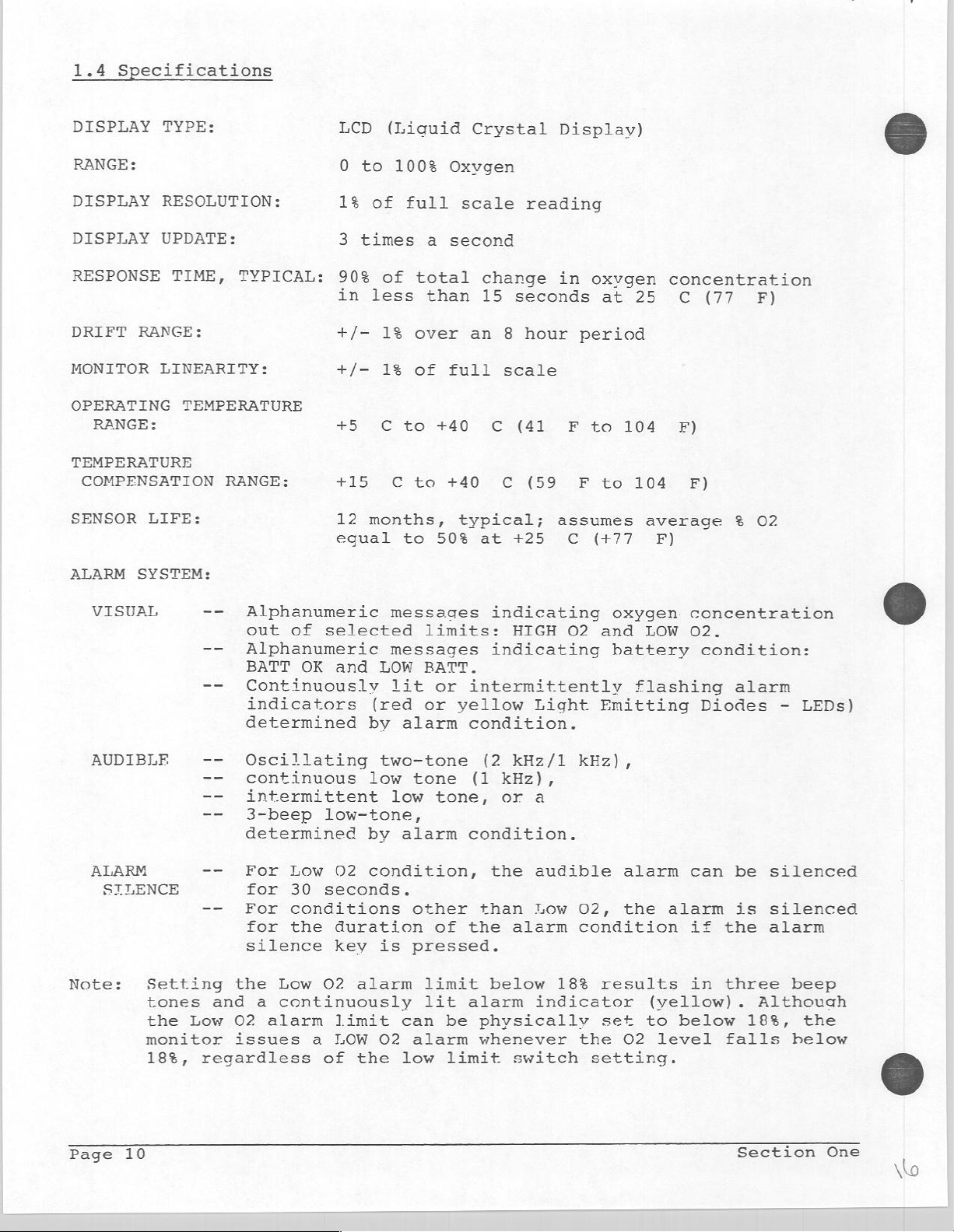
1.4
Specifications
DISPLAY
RANGE:
DISPLAY
DISPLAY
RESPONSE
DRIFT
MONITOR
OPERATING
TEMPERATURE
COMPENSATION
SENSOR
ALARM
RANGE:
RANGE:
LIFE:
SYSTEM:
TYPE:
RESOLUTION:
UPDATE:
TIME,
LINEARITY:
TEMPERATURE
TYPICAL:
RANGE:
LCD
0
to
1%
3
times
90%
in
+/-
+/-
#9
415
12
egual
(Liquid
100%
of
full
of
less
1%
1%
C
to
€
months,
to
a
total
than
over
of
110
to
50%
Crystal
Oxvgen
scale
second
change
15
an 8 hour
full
40
typical;
scale
С
ς
at
Display)
reading
in
seconds
т
(9ο
assumes
+25
oxvgen
at
period
во
r
to
G
(77.
concentration
25
104
-1045
average
E)
©
e)
F)
(77
%
E)
02
VISUAL
AUDIBLE
ALARM
Note:
SILENCE
Setting
tones
the
monitor
18%,
--
Alphanumeric
out
--
Alphanumeric
BATT
--
Continuously
indicators
determined
ーー
--
continuous
--
intermittent
--
3-beep
determined
--
For
for
--
For
for
silence
the
and
Low
02
issues
regardless
of
OK
lating
Low
30
conditions
the
Low
a
continuously
alarm
a
selected
and
LOW
(red
by
two-tone
low
low-tone,
by
02
condition,
seconds.
duration
key
is
O2
alarm
limit
LOW
02
of
the low
messages
limits:
messages
BATT.
lit
or
or
alarm
tone
low
tone,
alarm
other
of
pressed.
limit
lit
can
be
alarm
limit
indicating
HIGH
indicating
intermittently
yellow
condition.
(2
(1
Light
kHz/1
kHz),
or
a
condition.
the
audible
than
the
alarm
physically
whenever
Low
alarm
below
indicator
switch
O2
and
Emitting
kHz),
02,
condition
18%
results
set
the
setting.
oxygen
LOW
battery
flashing
alarm
the
(yellow).
to
02
level
concentration
O2.
condition:
alarm
Diodes
can
be
alarm
below
if
in
is
the
three
falls
-
silenced
silenced
alarm
beep
Although
18%,
helow
LEDs)
the
Page
10
Section
One
No
Page 17
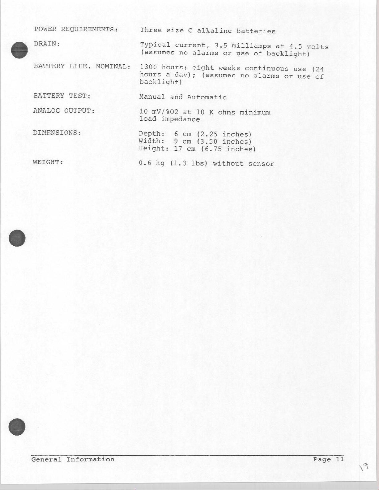
POWER
REQUIREMENTS:
Three
size
C
alkaline
batteries
S
DRAIN:
BATTERY
BATTERY
ANALOG
DIMENSIONS:
WEIGHT:
LIFE,
TEST:
OUTPUT:
NOMINAL:
Typical
(assumes
1300
hours
hours;
a
backlight)
Manual
10
load
Depth:
and
mV/%02
impedance
Width:
Height:
0.6
kg
current,
no
day);
Automatic
at
6
cm
9
cm
17
cm
(1.3
alarms
eight
(assumes
10
(2.25
(3.50
(6.75
lbs)
3.5
or
weeks
K
ohms
inches)
inches)
without
milliamps
use
continuous
no
minimum
inches)
of
alarms
sensor
at
4.5
backlight)
use
or
use
volts
(24
of
General
Information
Page
11
Page 18

Page
12
Section
Two
Page 19

2.0
SETUP
AND
CALIBRATION
This
receive
universal
section
components
describes
conditions
regularly
2.1
Setup
As
received,
batteries
to
the
monitor.
the
monitor
Note:
Read
before
1.
Install
as
outlined
it
(2.1),
mounting
you
the
(2.4),
to
must
the
three,
tells
will
alarms
ensure
the
be
If
should
operating
using
in
you
shows
clamp
be
the
and
the
5120
installed
the
be
the
size
Section
how
to
you
(2.2),
using
monitor
includes
accuracy
Oxygen
monitor
ready
instructions
monitor.
C,
alkaline
5.3C,
set
how
while
a
Monitor
and
is
for
up
the
to
attach
identifies
operating
generates
calibration
the
of
is
the
sensor
part
of a Modulus
operation.
in
batteries
omitting
monitor
the
probe
the
the
warn
to
procedure
displayed
fully
Section
Step
assembled,
assembly
3.
when
holder
controls
monitor
you
readings
must
II
3.2
you
first
or
and
(2.3),
specific
of
follow
to
(2.5).
however,
be
attached
Anesthesia
the
System,
NOTE:
convenience.
guarantee
Replace
2.
Attach
as
described
3.
Install
as
described
Three,
can
with
the
the
Size
Since
be
fresh,
sensor
in
sensor
in
C,
all
made
Size
assembly
Section
cartridge
Section
alkaline
batteries
as
to
C,
to
5.3A.
5.3B.
batteries
their
alkaline
the
into
have
service
batteries.
monitor
the
sensor
are
a
limited
life.
included
shelf-life,
assembly
for
probe
your
no
housing
Setup
Calibration
and
Page
13
A
Page 20

2.2
The
on
Two
A.
a
Mounting
5120
post
Oxygen
or
accessories
PORTABLE:
If
the
monitor
is
provided
is
not
in
bar
Refer
use.
Monitor
(shelf)
are
provided,
to
is
to
protect
can
Figure
used
in
be
the
as
the
used
area
one
for
5.
a
stand-alone
sensor
as
a
portable
of
intended
each
situation.
probe while
unit,
instrument
use
(*).
a
holder
the
monitor
or
mounted
Align
mounting
Screw
MOUNTED:
If
the
built
described
4
cm
(1-5/8
in
diameter.
The
monitor
ball
joint
Tighten
Screw
the
monitor;
housing.
Attach
used.
Position
large
the
probe
hole
the
bolt
Refer
monitor
into
a
below.
which
the
the
mounting
the
clamp
Loosen
the
retaining
holder
in
the
in
firmly
to
Figure
is
to be
system),
The
inches)
attachment
can
large
ensure
the
retaining
to
large
monitor
nut
back
attach
clamp
thick
be
clamp
a
the
to
to
with
the
of
(finger-tight);
6.
placed
can
or a pole
and the
swiveled
nut
into
firm
grip
shelf
retaining
the
desired
hold
the
retaining
the
monitor.
in a permanent
the
universal
be
attached
up
clamp
to
the
between
or
are
25
degrees
lock
threaded
pole
nut
where
to
viewing
monitor
pin and
do
not
mounting
to
to 5 cm
held
in
the
ball
hole
the
clamp
the
free
angle.
in
place.
the
use
location
a
shelf
(2
inches)
together
any
direction.
joint
in
the
and
monitor
the
ball
threaded
tools.
(not
clamp
up
to
by
in
back
the
is
joint.
Tighten
as
a
place.
of
monitor
to
be
the
The
(*)
Modulus
Page
14
oxygen
Anesthesia
II
monitor
can
System.
also
be
Refer
installed
the
to
systems:
in
System's
manuals
such
as
details.
for
Section
the
Two
10
Page 21

Figure
5.
Probe
Holder
Shelf
Mount
Pole
Mount
Figure
Setup
and
6.
Universal
Calibration
Mounting
Clamp
Page 22

2.3
Controls
and
Components
This
during
Functions
section
the
described.
(Refer
1.
to
BATTery
to
Note:
Modulus
set
the
the
power
will
left
prevent
Normally
is
sensor
sensor
stabilize
identifies
operation
are
Figure
turn
If
to
the
external
BATTery
source
sound,
on
turned
assembly
cartridge
and
defined
7
POWER
the
the
II
Anesthesia
OFF
and
on
page
Switch:
monitor's
monitor
position
power
POWER
is
then
indicating
battery
this
the
on;
power.
alarm.
monitor
no
warm-up
has
has
sensor. Refer
the
controls
maintenance
their
17)
This
battery
is
installed
System,
if
source
switch
turned
that
Turn
is
ready
is in
or
been
disconnected
been
to
and
of
effects
is a two
power
the
the
monitor
provided
the
off,
the
monitor
the
BATTery
for
standby
replaced,
the
note
components
the
5120
on
the
total
position
on
and
in a system,
battery
is
by
the
ON
position
an
intermittent
has
POWER
operation
is
required.
from
allow
on
page
encountered
Oxygen
off.
power
to be
system
been
switch
as
the
at
least
28.
Monitor.
system
rocker
such
as
switch
operated
connection.
and
the
low
tone
inadvertently
OFF
soon
as
However,
monitor,
five
are
switch
the
must
from
external
alarm
to
the
or
minutes
used
be
If
power
if
if
6
the
the
to
1A.
Automatic
switch
condition
corresponding
an
a.
b.
(*)
If
the
Anesthesia
switch
should
powered
determine
To
manual
Page
battery
16
is
audible
If
the
batteries
operates
backlight);
a
day,
the
of
When
operation.
condition
continuous
the
monitor
indicator,
should
(assumes
to
continue
ensure
monitor
System,
be
external
an
by
the
test
Battery
first
of
alarm
for
turned
the
batteries
messages
is
at
this
of
operation.
batteries
displays
and
sounds
no
use
uninterrupted
is
installed
the
internal
left
in
source)
condition
described
as
Test:
on
is
generated(*).
are
fresh
least
is
the
1,300
equal
The
batteries
reach
a
"LOW
3
to
operate
of
backlight),
Off
the
the
of
Whenever
(and
displayed;
periodically
is
tested
(size
hours
to
eight
monitor
the end
BATT"
low-tone
message,
properly
monitoring.
in
a
system,
batteries
position
not
are
internal
item
in
the
monitor's
automatically
and
C,
alkaline)
(assuming
weeks
displays
will
replace
allow
of
their
beeps.
for
(because
whenever
tested
batteries,
on
3
Battery
thereafter)
if
required,
the
.no
of
continuous,
a
"BATT
more
useful
lights
Although
approximately
the
such
the
batteries
as
the
the
the
automatically.
perform
page
18.
and
monitor
alarms
OK"
message
than
life,
yellow
the
Modulus
battery
monitor
Power
the
a
an
or
24
8
hours
the
monitor
6
hours
power
is
the
Section
use
hour
(LED)
II
©
of
if
@
Two
Page 23

c.
If
the
battery
monitor
-
an
-
the
1
the
-
the
goes
audible
yellow
LOW
digital
BATT
power
into
alarm
alarm
message
display
is
a
"shutdown"
sounds
indicator
appears
is
below
blank.
an
(intermittent
(LED)
acceptable
mode:
flashes,
on
the
low-tone)
display,
threshold,
,
and
the
Figure
Setup
7.
and
Oxygen
Calibration
Ohmeda
Oxygen
Monitor,
5120
Monitor
Front View
Page
17
Page 24

2.
a.
b.
DISPLAY:
to
show
also
battery
displays
The
monitor
oxygen
Messages
-
The
LOW
concentration
refer
-
The
HIGH
oxygen
limit
-
The
BATT
require
this
-
The LOW
the
section.
batteries;
The
oxygen
the
concentration
alphanumeric
status.
displays
in
1%
increments.
appear
02
message
is
to
item
02
4
message
concentration
selected;
OK
message
attention
BATT
message
on
less
of
refer
at
refer
monitor
of
oxygen
the
display
appears
than
this
section.
appears
is
greater
to
indicates
this
indicates
to
items
uses
a
oxygen
messages
concentrations
to
whenever
the
low
whenever
than
item
4
of
that
time;
refer
a
1A
Liquid
in
for
indicate
the
02
the
this
the
low
voltage
and
Crystal
numeric
alarm
displayed
alarm
the
displayed
high
section.
batteries
to
items
3b
of
Display
form.
conditions
from
various
"00"
limit
02
alarm
do
1A
condition
this
section.
The LCD
and
to
"100"%
conditions.
oxygen
selected;
not
and
3b
of
(LCD)
of
3.
a.
b.
BATTery
position
display
and
to
are
operational.
A
Liquid
depends
visible.
difficult
activates
display.
to
turn
Note:
System,
The
condition
the
top
circuitry
is
displayed,
monitoring
Note:
System,
of
power
TEST
switch'used
in
subdued
verify
Crystal
on
When
to
an
The
the
If
the
the
half
(along
If
the
the
is
(CÔ-)
that
ambient
the
read.
internal
light
backlight
monitor
backlight
of
of
the
replace
of
the
monitor
batteries
off and
and
CIRCUIT
to
turn
lighting,
the
display
Display
light
room
Pressing
light
remains
off.
is
is
the
batteries
switch
with
the
the
patient.
is
can
the
TEST
on
the
to
perform
circuitry
(LCD)
to
make
light
installed
always
installed
BATTery
is
the top
that
on
until
(BATT
backlight).
batteries
only
Switch:
backlight
does
can
be
not
the
digits
low the
half
continuously
the
in a Modulus
on
whenever
be
TEST)
to
in a Modulus
tested
POWER
This
a
manual
and
the
produce
display
of
switch
checked
activates
If
the
ensure
if
switch
is a three-
for
viewing
battery
alarms
light.
(characters)
may
the
switch
illuminates
is
again
II
Anesthesia
the
system
manually.
battery
LOW
BATT
uninterrupted
II
Anesthesia
the
external
is
on.
the
test,
It
be
pressed
is
Pressing
test
message
source
the
on.
Page
18
Section
Two
AM
Page 25

The
electronic
periodically
messages,
functional.
(Circuit
a
high
messages
are
turned
If
any
sequence,
and
Test)
concentration
are
of
the
the
circuitry
to
verify
the
Pressing
electronically
displayed
on
(along
monitor
monitor
visual
of
with
of
that
alarm
the
bottom
oxygen
and
the red
one
functions
must
not
the
monitor
the
digital
indicators
portion
substitutes
(88
short
fail
be
used
to
and
audio
to
should
display,
of
102
yellow
alarm
operate
until
(see
the
a
voltage
%).
repairs
be
the
item
switch
All
alarm
beep).
during
tested
displayed
6)
are
simulating
alarm
indicators
the
are
HIGH
test
made.
02
[00
Oxygen
Oxygen
Figure
Setup
8.
and
Calibration
Monitor
Monitor,
Front
View
(continued)
Page
19
25
Page 26

Alarm
and
Limit
the low
concentration
Low
02
and
with
LOW
than
LOW
flashes
corresponding
02:
02
the
message
Whenever
value
and
Switches:
oxygen
is
High
set
is
an
oscillating
alarm
less
02
alarm
alarms.
the
by
displayed,
Use
these
limits.
than
or
limit
displaved
the
Low
two-tone
switches
When
greater
switch,
oxygen
02
alarm
the red
to
the
displayed
than
the
concentration
limit
alarm
audible
set
the
values
monitor
switch,
indicator
alarm
the
oxygen
will
sounds.
high
set
is
the
(see
oxygen
by
the
respond
less
item
6
6)
5.
NOTE:
yellow
beeps.
monitor
regardless
is
set.
HIGH
than
02
02:
the
message
flashes
Note:
the
HIGH
flush
Alarm
procedures.
Indicators
Emitting
The
red
the
value
The
yellow
--
the
High
--
the
--
the
Setting
alarm
If
the
will
of
Whenever
value
is
and
an
Setting
02
alarm;
Diodes
LED
set
LED
displayed
O2
switch,
sensor
batteries
the
Low
indicator
displayed
issue
how
displayed,
set
a
far
a
by
intermittent
the
High
this
(00):
(LEDs)
flashes
by
the
flashes
%02
is
disconnected
have
02
limit
(LED)
concentration
high
displayed
below
the
the
priority
High
02
mode
The
to
visually
whenever
Low
02
whenever
is
greater
discharged
on,
18%
oxygen
02
yellow
low-tone
alarm
is
alarm
the
switch.
or
switch
accompanied
the
alarm
below
falls
alarm
Low
02
concentration
limit
alarm
(same
indicator
alarm
limit
useful during
switch
silence
indicate
displaved
than
the
defective,
below
value
a
useable
18%
by
below
as
alarm
switch,
sounds.
to
100%
switch
an
alarm
02
is
or
turns
three
18%,
LOW
limit
"00"
oxygen
includes
less
set
level.
the
low-tone
the
02
alarm)
switch
is
greater
the
HIGH
(see
item
disables
condition.
than
by
the
two
6)
Light
Alarm
6.
"alarm
visual
than
for
In
continuously
period.
Page
The
yellow
-- a LOW
-
the
BATTery
Low
-- a system
Silence
silence"
alarm
02
Low
the
duration
either
20
case,
LED
is
02
limit
(monitor)
Switch
switch
indicators
alarm
of
a
(not
continuously
condition
switch
failure
Xx):
(
turns
remain
conditions,
the
alarm
flashing
flashing)
occurs,
is
set
is
During
off
active
the
condition.
alarm
for
lit
whenever
below
sensed.
a
alarm
the
audio
indicator
duration
the
18,
or
alarm,
02
Low
for
throughout.
alarm
switches
of
30
is
the
pressing
seconds;
other
For
silenced
to
Alarm
being
Silence
Section
the
the
on
G
Two
20
Page 27

HIGH
02
|
IDO
LI
LI
LOW
02
Figure
7.
Sensor
housing
and the
The
be
Setup
9.
Assembly:
sensor
installed
and
Calibration
connector
Oxygen
(probe)
cartridge
before
Monitor,
The
for
the
which
is
use
Front
sensor
oxygen
joins
not
(refer
View
assemblv consists
sensor
the
part
to
(continued)
sensor
of
the
section
cartridge,
assembly
sensor
of
5.3.B).
the
the
to
assembly;
coiled
the
monitor.
it
cable,
must
Page
21
2
Page 28

11
O
VOLTS
1.5
CAES
bt,
VOLTS
1,5
ere
VOLTS
15
3
Preoperative
See
Operation & Maintenance
1,
Depress
displayed,
alkaline
"Batt,
Depress
and
Calibrate
“Low
*Low
20%.
Calibrate
minutes
minutes
If
the
cartridge.
replacement
Checklist
and
hold
immediately
"C"
size.
Power”
on
“Circuit
102.
to
21%
O,"
alarm
O;”
to
below
Alarm
must
to
99% once each
to
stabilize.
after
returning
unit
will
not
See
Operation & Maintenance
instructions
“Batt.
Retest.
and external
Test”
switch.
in
room
adjustment
21%
and
sound
Display
calibrate
CT
PTP
NY
Manual
Test”
change
“Batt.
air,
to
turn
to
room
for
switch.
all
three
Test”
must
power
Display
allow 2 minutes
22%.
Alarm
“High
month,
or
must
return
air.
to
either
21%
detailed
If
off.
must
O,“
as
instructions.
“Low
Batt.”
batteries,
must
alarm
required.
or
Manual
using
be
performed
(e.g.
Modulus
read
between
tostabilize.
sound.
adjustment
to
21%21%
99%,
replace
for
message
fresh
with
II)
88
Tum
Set
to
allow
2
within
3
probe
test
and
is
Figure
Page
22
10.
Battery
Compartment
Section
Two
Page 29

(Refer
8.
Front Cover:
for
and the
to
easy
Figure
access
calibration
10
The
on
to
page
lower
the
control.
22)
portion
Preoperative
of
the
front
Checklist,
panel
the
flips
down
batteries,
Preoperative
brief
monitor
monitor
Refer
πο,
Batteries:
alkaline
a
Section
1%
CALibration
is
calibration
the
in
Similar
diminishes
change.
Check
oxygen
Section
procedure
a
is in
to
manual
5.3C
proportional
monitored
the
Preoperative
to
the
to
2.5
Checklist:
to be
new
patient.
operating
section
The
3.1
oxygen
batteries(*).
battery
Control:
test
describes
to
control
oxygen
batteries,
with
monitor
assure
time.
periodically
the
details
The
followed
Follow
order.
for
the
monitor
The
monitor
described
how
to
The
oxygen
the
oxygen
is
used
concentration.
Checkout
the
output
The
CALibration
monitor's
the
calibration
inside
daily
this
Preoperative
is
procedure
powered
includes
in
items
replace
sensor
concentration
to
set the
Procedure.
from
with
specified
of
the
front
or
whenever
Checkout
by
1A
spent
produces
displayed
Room
a
air
the
sensor
adjustment
"100%"
accuracy.
procedure.
cover
preparing
to
ensure
Procedure.
three,
an
automatic
and
batteries.
monitored.
3b
a
size
of
current
reading
(21%
02)
cartridge gradually
compensates
concentration
contains
that
C,
and
this
The
to
is
specified
a
to
the
section.
that
match
for
of
the
The
against
calibration
(*)
monitor
the
POWER
calibration
the
If
switch
inadvertent
is
monitor
should
Off)
to
control
movement,
required.
installed
is
operated
be
conserve
to
is
housed
but
in
from
the
behind
provides
Modulus
a
the
monitor's
the
II
system's
front
easy
internal
access
Anesthesia
power
panel
when
System,
source
batteries.
to
guard
(BATTery
Setup
and
Calibration
Page
23
Page 30

(Refer
12
Sensor
the
13.
Output
to
--
WARNING:
to
result
value
Refer
description
MOUNTING:
14,
probe
be
clamp
to
three
an
- a
- a
pin
used
Figure
(Input)
back
of
the
Connector:
features
analog output
digital
connection
Connect
5
of
the
in an
displayed
to
Appendix
of
If
holder
in
a
instead.
11
on
page
Connector:
monitor
The
of
output
for
only
analog
output
on
the
A
each
the
monitor
to
this
"permanent"
Refer
25)
The
through
output
the
5120
of
the
displayed
indicating
remote
a
high
output
alarm
voltage
oxygen
for the
feature.
is
threaded
location,
to
section
sensor
an
connector
Oxygen
a
impedance
connector.
that
monitor.
pin
connections
intended
insert;
1.2,
assembly
8-pin
Monitor:
percentage
sensed
silencing.
is
lower
for
if
attach
Accessories.
modular
provides
alarm
device
Improper
than
and
portable
the
monitor
the
cable
connects
jack.
remote
of
oxygen,
condition,
(at
least
loading
the
corresponding
a
detailed
use,
is
universal
to
access
and
10 K ohms)
will
attach
to
mounting
the
e
Page
24
Section
Two
20
Page 31

14
13
Figure
11.
Rear
View
À
Caution:
device
to
sale
Output
Federal
by
cr
on
Setup
and
Calibration
Page 32

2.4
Alarms
The
5120
present
limits,
changed
of
alarm.
summarized
Oxygen
at
its
sensor.
alarms
and
condition.
The
alarms
in
Chart
Monitor
messages
The
1
displays
If
severity
are
on
the
sensed
are
described
page
38.
the
percent
values change
generated
of
the
in
to
condition
the
following
of
oxygen
alert
concentration
beyond
the
operator
determines
paragraphs
selected
the
and
of
the
level
NOTE:
and,
(not
In
30
alarms,
Pressing
if
flashing)
the
seconds
condition.
1.
If
limit
2.
If
alarm
3.
As
generates
flashing,
case
the
the
of
(if
alarm
detected
set
Audible
Red
Low
the
detected
limit
Audible
Yellow
HIGH
the
batteries
the
for the
a
the
point
alarm
02
message
set
Alarm
02
two
"Alarm
causes
Low
02
Low
remains
oxyaen
or
alarm
indicator
oxygen
point,
alarm
message
reach
levels
Silence"
the
duration
alarm,
02
alarm
silent
concentration
below
concentration
a
indicator
the
of
alarm:
alarm
of
the
condition
18%,
(LED)
less
end
switch
indicator
the
alarm
for
a
urgent
(LED)
of
Alarm
the
high
-
oscillating
-
flashing
-
displayed
-
intermittent
-
flashing
-
displayed
their
turns
to
Silence
will
again
still
duration
falls
priority
rises
alarm
useful
off
be on
exists);
of
below
alarm
above
is
generated:
life,
the
audible
continuously
period.
sound
the
the
after
for
current
Low
is
two-tone
the
High
low-tone
the
alarm
the
other
alarm
O2
alarm
generated:
(high/low)
02
monitor
1st
LEVEL
LOW
Yellow
Audible
Although
approximately
replace
2nd
LEVEL
Display
Audible
Yellow
LOW
The
must
-
CAUTION:
BATT
alarm
alarm
the
-
SHUTDOWN:
-
alarm
alarm
BATT
monitor
replaced
be
message
indicator
monitor
the
6
batteries
Blank
indicator
message
indicates
hours
before
(LED)
should
(assumes
ensure
to
(LED)
a
high
the
-
displayed
-
lit
-
three
continue
no
uninterrupted
-
intermittent
flashing
-
-
displaved
priority
monitor
(continuously)
(3)
low-tone
operate
to
backlight),
of
use
alarm;
be
can
monitoring.
low-tone
the
used.
beeps
properly
hatteries
Section
for
Two
Page 33

4.
If
the
Low
O2
alarm
limit
switch
is
set
below
18%:
о
을
5.
If
disconnected:
6.
If
a
The
the
7.
When
Power
the
set
is in
is
under
Audible
Yellow
the
sensor
Audible
Yellow
Display
the
System
"Watchdog"
Fail
Audible
Yellow
Display
monitor
troubleshooting
used
batteries.
to
turned
in a Modulus
switch should
the
On
use,
the
off,
battery
Alarm
alarm
assembly
alarm
alarm
alarm
alarm
alarm
cannot
If,
position
monitor
indicating
power.
indicator
is
indicator
circuitry
is
generated:
indicator
be
used
guide
II
be
set
however,
while
will
(LED)
interrupted
(LED)
detects
(LED)
until
repairs
(section
Anesthesia
to
the
the
monitor's
the
Modulus
generate
that
the
-
three
-
lit
(continuously)
by
-
intermittent
-
flashing
-
shows
a
computer
-
continuous
-
lit
(continuously)
-
blank
5.2) for
System,
Off
position
an
alarm
monitor
(3)
low
component
00
failure,
low-tone
are
made,
details.
the
to
Batt
II
Power
Anesthesia
when
remains
tone
failure
low-tone
refer
monitor's
conserve
switch
the
turned
beeps
to
System
system
on,
or
Batt
is
is
Audible
Display
alarm
-
intermittent
-
shows
oxygen
low-tone
concentration
Setup
Calibration
and
Page
27
2
る
Page 34

2.5
Calibration
Calibrate
as
required)
The
"100%"
oxygen
NOTE:
and
minutes.
the
monitor
calibration.
installed,
cartridge
just
If
five
removed
allowed
disconnected
of
layer
(if
of
the
using
02
sensor.
Before
allow
sensor
before
the
minutes
12
hours.
disconnected
the
the
The
for
was
sensor
from
to
that
cell.
Oxygen
calibration
calibrating
five
(cartridge)
at
In
the
calibration.
or if
its
stabilize
(or
The
accumulates
Monitor
a
concentration
sensor
minute
least
cases
five
removed
assembly
protective
removed
stabilization
and
to
12
where
minute
from
the
for
exposed
at
regular
is
required
the
monitor,
stabilize
stabilization
assembly
hours
has
new
as
from
on
immediately
a
new
stabilization
its
been
sensor
packaging,
many
its
the
galvanic
to
intervals
of
oxygen
to
verify
turn
for
at
time
has
been
sensor
sealed
disconnected
hours
is
oxygen)
protective
cartridge
the
as
packaging),
required
cell
greater
the
the
least
assumes
connected
preceding
cartridge
assumes
for
has
monitor
the
to
of
impeding
(once
than
linearity
monitor
five
that
packaging
more
been
sensor
up
to
remove
the
the
each
99%
on
that
to
the
the
has
been
the
than
previously
must
sensor
has
a
maximum
an
output
be
oxide
month
("100%").
of
been
or
the
If
in
doubt,
time
calibration
linear.
additional
and
1.
2.
3.
4.
5.
NOTE:
sensor
6.
of
repeat
Set
the
HIGH
Turn
Introduce
and
Adjust
99%
Remove
The
21%
Set
alarm
O2
the
allow
02.
display
+/-
If
cartridge
the
disconnect
However,
limit)
allow
is
time
the
HIGH
alarms.
monitor
the
the
the
Calibration
the
probe
1
digit.
display
the
HIGH
the
and
successful
if
the
for
the
calibration.
O2
alarm
ON
and
oxygen sensor
display
from
must
is
02
to
stabilize
is
not
alarm
enable
monitor
perform
the
calibration
monitor
limit
allow
to
stabilize
Control
the
within
not
linear
limit
the
to
the
sensor
to
switch
it
into
"100%"
within
and
to
HIGH
stabilize
calibration.
can
is
not
stabilize
to
to
stabilize
a
"100%"
(approximately
until
must
"30"
02
02
three
the
alarms.
the
and
+/-
be
(or
for
be
assumed
successful,
"00"
to
concentration
display
expose
minutes
1%
replaced.
to
the
If
(up
to
disable
(see
it
tolerance
desired
a
presumed
the
to be
12
hours)
note
two
indicates
to
and
indicate
allow
the
above).
of
minutes).
room
High
air.
range
02
oxygen
the
Page
28
Section
Two
2A
Page 35

3.0
OPERATION
6
This
section
functions
and
instructions
3.1
Preoperative
To
ensure
following
-
the
-
the
-
the
being
-
fresh
NOTE:
the
inside
procedure,
reference
of
this
This
procedure
displays
in
detail
of
that
checks
monitor
sensor
monitor
dropped
batteries
A
condensed
to
monitor
and
in
contains
the
the
is
assembly
(or
of
the
use the
assure
have
assumes
alarms
Section
a
5120
on
Checkout
Oxygen
how
oxygen
daily.
returned
sensor)
or
severely
have been
version
monitor's
Preoperative
yourself
been
generated
2.3.
procedure
to
use
Procedure
monitor
Also,
to
has
been
has
of
front
skipped.
that
the
to
Monitor
the
is
follow
clinical
cleaned
received
bumped,
installed.
the
following
cover.
Checklist
that
by
no
user
the
help
are
monitor
working
this
use,
important
is
familiar
monitor.
determine
working
effectively
properly,
procedure
or
replaced,
a
mechanical
procedure
After
on
the
These
properly
you
cover
steps
with
that
make
whenever
shock,
is
are
in
the
are
(3.1),
(3.2).
the
printed
familiar
as
a
convenient
the
checkout
controls,
explained
such
as
on
with
this
e
NOTE:
condition,
as
If,
described
WARNING:
Preoperative
has
been
.
Place
Set
Set
Set
a.
b.
c.
d.
the
the
the
The
The
The
The
NH
# W
approximately
The
e.
After
alarm
the
If
(*)
Anesthesia
Operation
during
replace
in
section
If
the
Checkout
corrected.
the
sensor
Low
O2
High
monitor's
display
LOW
02
red
visual
backlight
audible
seconds,
30
silence
monitor
System,
the
procedure,
the
monitor
in
alarm
O2
alarm
should
message
and
five
alarm
switch.
is
turn
batteries
5.3C
and
fails
Procedure,
room
air
limit
limit
BATTery
indicate
should
alarm
the
indicator
BATT
seconds.
should
when
installed
system's
the
the
with
repeat
to
do
switch
switch
POWER
be
not
the
in
monitor
three,
this
respond
not use
(21%).
to 25.
to
switch
approximately
displayed.
(LED)
message
OK
sound
alarm
a
does
system,
power
indicates
size
checkout
as
described
it
25.
to
On(*).
should
should
approximately
for
sound,
such
off.
C,
until
21%
as
a
alkaline
procedure.
the
02.
flash.
remain
do
the
LOW
BATT
in
the
malfunction
on
30
press
not
Modulus
batteries
for
seconds.
the
II
Page
29
%5
Page 36

When
(one
The
the
audible
digit
audible
less
alarm
alarm
than
should
sounds,
the
set
displayed
turn
off.
the
LOW
reading).
02
alarm
limit
to
20
Press
and the
switch
the
Note:
(installed
Calibrate
a.
With
until
b.
Then,
Press
a.
The
b.
The
c.
All
d.
The
Release
message
Turning
Then,
a.
The
b.
The
and
release
BATT
again
If
the
in
the
the
the
readjust
and
hold
alarm
display
messages
red
and
the
should
both
set the
alarm
vellow
the
OK
message
to
monitor
a
system),
monitor
sensor
display
the
the
tone
Circuit
thumbwheels
tone
should
(4)
yellow
remain
LOW
alarm
should
02
should
Batt.
should
is
to
room
the
connected
the
21%
turn
in
indicates
control
Circuit
beep
indicate
should
alarm
Test
indicator
switch,
on
for
simultaneously,
alarm limit
sound three
Test
switch.
be
backlight
backlight
02
as
air
(21%)
20%
until
Test
be
switch
once.
88
on.
indicators
onlv
approximately
switch
(LED)
displayed
off.
to
an
is
follows.
adjust
02.
the
and
to
102
(LEDs)
the
low-tone
should
The
backlight
for
external
always
the
display
note
%
02.
backlight
five
set the
to 17.
light
five
power
on.
CALibration
just
the
should
seconds.
Low
beeps.
and
should
seconds.
source
indicates
following.
be
on.
and
the
02
switch
remain
light
Press
control
21%.
RATT
to
lit.
OK
19
10.
ть.
2.
13.
14.
This
Set
Set
the
displayed
a.
The
b.
The
c.
The
Press
a.
b.
c.
d.
Set the
displaved
Set
displayed
a.
b.
c.
Set the
displayed
completes
the
the
The
The
The
After
the
The
The
The
alarm
LOW
02
reading).
audible
red
alarm
LOW
O2
"alarm
alarm
flashing
LOW
02
30
Low
02
reading).
High
reading).
audible
yellow
HIGH
02
High
reading).
the
limit
alarm
alarm
message
tone
ZED
message
seconds
alarm
02
alarm
alarm
alarm
message
02
alarm
preoperative
switches
limit
should
indicator
should
silence"
should
should
should
the
limit
The
limit
should
indicator
limit
The
switch.
be
alarm
low
should
high
to
switch
sound
(LED)
be
silenced
stop
remain
switch
02
switch
sound
switch
02
checkout procedure.
their
to
(oscillating
should
displayed.
flashing
should
to
alarms
(intermittent
(LED)
be
displayed.
alarm
original
22
for
on.
again
20
to
should
to
(one
flash.
approximately
(on
(one
should
20
(one
22
(one
should
digit
two-tone).
continuously).
sound
digit
be
(with
inactive.
digit
low-tone).
flash.
digit
be
inactive.
setting.
greater
30
LED
less
less
greater
than
seconds.
flashing)
than
than
the
the
than
the
the
Calibrate
reguired;
Page
30
the
refer
monitor
to
to
Section
"100%"
2.5.
oxygen
once
a
month
or
as
otherwise
Section
Three
Page 37

3.2
To
1.
2.
3.
Operation
operate
be
familiar
understand
know
Section
the
how
oxygen
its
the
1.3).
with
alarms
monitor
monitor
its
controls
derives
effectively
and
indicators
(refer
its
the
to
(refer
readings
user
Section
to
(refer
must:
2.3),
Section
to
2-2},
Before
Procedure
Section
Calibrate
Procedure)
Once
to
refer
a
month,
"100%"
to
NOTES
When
a
ventilator
condense
temperature
of
the
diffusion
02
concentration
CAUTION:
to
reduce
using
to
3.1.
to
O2
θεος
ON
the
breathing
the
oxygen
ensure
room
or
to
ίση
APPLICATION
oxygen
on
resistance
When
moisture build-up
air
whenever
or
as
verify
2.5.
sensor
or
an
the
surface
is
lower
in
monitor,
that
(21%)
the
required
the
anesthesia
than
gas.
and
display.
use,
the
monitor
daily
monitor
otherwise,
linearity
is
used
of
or
The
may
the
perform
(Step
is
in
gas
the
sensor
equal
condensate
result
sensor
on
its
the
is
working
7
of
returned
calibrate
of
the
the
patient
machine,
if
to
the
acts
in
a
should
sensing
Preoperative
properly,
Preoperative
to
clinical
the
oxygen
water
the
dew
as
lower
always
surface.
sensor,
circuit
sensor's
point
an
than
be
Checkout
refer
Checkout
monitor
of
vapor
additional
will
temperature
actual
pointing
to
use.
down
In
the
patient
of
the
breathing
Continuous
reduce
READINGS
5000
containing
of
preferably
circuit,
NOTE:
of
same
the
percent
the
sensor
The
oxygen
percentage
Operation
exposure
service
IS
NOT
hours
1%
be
service
oxygen
at
the
circuit
gas
AFFECTED).
CO2
by
for
0.1%.
located
life
monitor
point
that
of
humidifier.
of
the
life
-
of
CO2.
five
However,
in
reduction
of
is
present
a
ventilator,
oxygen
the
The
Using
hours
the
inspiratory
provides
sensing.
sensor
oxygen
service
the
would
since
as a result
throughout
sensor
sensor
information
This
place
to
life
reduce
the
sensor
section
is
the
the
sensor
CO2 gas
(ACCURACY
of
the
in a gas
the
service
should
of
of
C02
on
the
not
necessarily
patient
mixture
sensor
mixture
the
is
minimal.
presence
ahead
can
OF
is
life
patient
the
circuit.
Page
Page 38

OPERATION
1.
Insert
a
Adapter
(Ohio)
22mm
the
oxygen
tee
manifold
Kit
for
Absorber
probe
the
is
optional.
into
is
supplied
inhalation
the
gas
with
check
stream
the
valve
to
monitor,
of
an
be
monitored;
a
Ohmeda
Dome
Attach
outlet
Attach
manifold.
Insert
sensor
cord
CAUTION:
reduce
2.
Turn
approximately
tailor
without
Js
ЗЕЕ
desired
display
greater
4.
Continue
the
(such
the
the
vertically,
end
When
moisture
the
the
the
Low
Е
alarm
indicates
than
female
as
patient
oxvgen
facing
in
build-up
monitor
alarm
intrusion
O2
points.
the
using
the
up.
use,
30
and
the
end
of
inspiratorv
breathing
sensor
with
the
on
On.
The
seconds
limits
of
the
an
02
selected
monitor
the
Tee
circuit
probe
the
sensor
sensor
its
should
sensing
audible
after
to
the
an
audible
High
The
O2
alarms
concentration
limits.
for
manifold
outlet
into
opening
alarm
turn
current
alarm
will
as
long
of
to
the
the
15mm
always
surface.
is
on;
this
oxygen
alarm.
limit
be
one
as
to
an
appropriate
a
CO2
absorber).
male
port.
facing
be
pointing
silenced
allows
concentration
switches
activated
digit
less
required.
end
down
of
Mount
for
you
to
when
than
the
and
down
time
the
22mm
the
the
to
to
the
or
a.
b.
Note:
switch
silence
turned
If
the
Low
02
the
red
is
displayed.
If
the
High
alarm
is
displayed.
The
audible
(Low
until
off:
monitored
limit
alarm
monitored
02
limit,
indicator
02
alarm
the
they
alarm
next
are
oxygen
or
below
indicator
oxygen
an
intermittent
(LED)
can
will
occurrence).
active
concentration
18%,
(LED)
concentration
flashes
be
silence
throughout
an
oscillating
flashes,
and the
silenced
for
The
low-tone
using
30
seconds;
visual
the
alarm
drops
two-tone
and
exceeds
alarm
HIGH
02
the
alarms
condition.
below
the
message
alarm
other
the
alarm
LOW
02
the
selected
sounds,
silence
alarms
cannot
selected
sounds,
message
the
vellow
will
be
Section
Three
Page 39

5.
Alarm
Setting
yellow
6.
THINGS
a.
b.
7.
After
sterilization
situation.
limits
the
alarm
TO
If
the
reaching
batteries
Section
If
sensor
five
assembly
between
on
minutes
page
use,
can
Low
indicator
REMEMBER:
LOW
BATT
the end
(three,
5.3C.
assembly
is
reconnected.
cases
28.
turn
procedures
be
02
alarm
message
to
stabilize
or
the
changed
(preceded
of
their
size
is
for
overnight
monitor
while
limit
below
by 3 beep
appears,
useful
C,
alkaline)
disconnected
the
Do
not
off
and
in
Section
the
monitor
18%
the
life.
sensor
disconnect
storage.
follow
4.1
results
batteries
Replace
as
described
from
after
that
is
tones).
the
monitor,
the
the
Refer
the
cleaning
apply
in
operation.
in a continuous
are
the
in
allow
sensor
sensor
to
the
NOTE
and
to
your
Operation
Page
33
A
Page 40

SOON,
peouells
siueunsnlpe
900
0}
460
Spuddes
uuJele
06
40)
444816
lenlul
elqlpnV。
wolle
cpl
ezllqels
“peloeuuoosIp
‘asn
40)
slueuuoo
Apee』
Josues
JOjIuOW
上
O
ol
비씨
MO]
9
Aolle
on
un
lu6lyoeg
uj
pue
suuejy
|
46090
'sÁejd:
‘LE
Heu
Jo
Wewwns
eBessopl
:uolejedo
an
908
NO
10)
20%
Ne
Ao1|
JO
908
NO
Nd
10)
|
?O
Ao]
|
2O
u6HH
40
Ayeuq
9037
4108
o
No
2
uo
ueuj
S88]
20%
а
90809
eidlpnV
MEN
yous
00098
|
ュー-
4
esuodsed
JOYUOW
Un
eq
ueo
uuele
elqipny。
о
ЧАН
20%
ore
NO
Ал
μη
J
e491
uew
sey
20%
10
UuonBJnp
uondpuoo
Jol
uuele
paoualls
JO
uonpuog
sejeoIPul
UOYM
NOLLOVO
JO1IUO
uuely
20%
snonuluoo|
후
108
20
ub
08441
20
MOT
”suol-wo1
auull
uuele
ος
ο
4641
781681
81
mojeq
Jes
«Ὁ
ΜΟΙ
20%
A
Sy
sdesg
.
BL
mojeq
“O
чин
Jes
n
.
peAeldstp
uonipuod
pelqeslp
Suuely,
suuele
00
4841
Jou
20
?O
UBIH
BIH。
10)
pojgesip
20%
0]
00,
195
‘MOI
Neg
1891
Neg
Ssolq
NO
20%
.
NO
1901
108
POIUANS
sooneg
WIEIE
esejdos
elqpny,
Auo
Jo
14614060
unl
4961
ol
dolms
908
NO
G
40)
88
이
NO
008
9
10)
1
NO
NO
NO
MOIS
a
peH
A
.
MONO,
19961.
‘Spucdes
5
10)
‘pessaldap
резевел
paldnualulun
quaned
ol
1981
seueheq
108,
цоимз
40109
이
9006
иецм
σοι
sfichufudo]
ος
jo
6uuoluou
92eId9H
eunsue
20%
NO
snonuluoo|
TN
auo¡-mo7
sdeog
06441
ΘΘΕΙΟΛ.
Aened
MOT
эа
UONEINP
uouipuoo
иво
40616
10}
40016
PadwalI
aiqipny,
до
земецеа
„UMOPINUS,
зоваец
U
JOJUOW
‘орош
31489
|
№
“a
1484144
euol-won
하
미
(umopinys)
реблецоза
sopopeg
peioeuuooe』
eq
poo6
ued
Wee
aiqipny,
00
0}
19
AIdsi
JueMNIluuelul
4osueg
wueje
lhun
elqlpnv,
S|
peouells
HOSN
ヨ
S
uey
uuelqoJd
Josues
‘ро
un
wous
uilw
UN
이
yuel9
00
Snonuluoo
euo」-Ao]
peioeuuooslp
eAlioejep
eiSAS
Jo
148
Senllej
9q
uoheJnp
ugo
ea
40196
uuele
Joj
04005
/
이
1910984
Aolle
人
HL
JOMOd
3
peouells
elqipnv,
ol
Neg
enuluoo
enewmou
lw
'uolouny
Joluom
0%
snonuuoo
N
QUO
L-MO'
MOT
|
ueuw
ed
релошен
SS
ano
o
Леш
1епашоо
'uo
euo」-Ao]
・
eines
uohlpuoo
uuele
jo
JO
Jemod
9q
pinous
leujelxe
uoilws
Bulsn
Jemod
ueym
Få
No
sdeeg
UO
SI
YO]IMS
Page
34
Section
Four
ud
Page 41

4.0
OPERATOR
MAINTENANCE
Calibrate
month
or
greater
calibration
thereby
the
range
Cleaning
The
batteries
and
have
are
covered
The
service
installed
maximum
replace
The
service
refer
If
the
to
monitor
deviation
replace
NOTE:
the
If
Repair Policy
the
as
otherwise
than
99%
is
assuring
of
the
and
sterilization
a
limited
in
life
and the
use
of
batteries
life
the
introduction
is
excessive
the
sensor
the
monitor
5120
Oxygen
("100%"),
required
the
readings.
and the
service
Section
of
the
accumulated
the
monitor between battery
only
of
the
cannot
cartridge.
and
Monitor
required)
refer
to
verify
specified
accuracy
recommendations
oxygen sensor
life;
5.0,
Service
batteries
use-time
with
be
when
requires
"fresh",
oxygen
on
page
calibrated
the
sensor
additional
Procedure
at
regular
using
to
a
Section
the
cartridge
replacement
Procedures.
depends
size
is
1
to
to
"100%"
in
Section
intervals
concentration
2.5.
linearity
of
the
are
are
procedures
on
their
of
the
monitor.
changes,
C,
alkaline
affected
realize
21%
in
room
O2
calibration
service
5.1.
The
of
the
monitor
covered
expendable
condition
always
by
maximum
air
or
(once
of
oxygen
"100%"
oxygen
throughout
in
Section
for
To
realize
batteries.
several
service
or
if
is
performed,
repair,
each
02
sensor,
4.1.
items
these items
when
factors;
life.
the
refer
to
Operator
Maintenance
Page
35
Page 42

4.1
Cleaning
All
parts
cartridge,
in a mild
Isopropyl
and
of
the
refer
liquid
alcohol
Sterilization
oxygen
to
monitor
section
detergent
can
be
used
(with
4.1C)
solution
if
the
can
be
(wetting
further
exception
cleaned
agent).
cleaning
with
is
of
the
a
cloth
required.
sensor
moistened
©
CAUTION:
saturate
Sterilization
three
A.
Monitor
B.
Sensor
C.
Sensor
Each part
separately
Use the
or
immerse
sections:
assembly
assembly
cartridge.
has
to
of
individual
ensure
sterilization.
NOTE:
After
cleaning
Checkout Procedure
functioning
WARNING:
Preoperative
has
been
A.
Monitor
In
most
is
sufficient.
moistened
properly.
If
the
Checkout
corrected.
Assembly
cases,
in
recommended
the
monitor.
the
various
(electronics
(less
that
and
in
Section
monitor
Procedure,
cleaning
If
required,
disinfectant
cleaning
parts
package),
cartridge)
sterilization
they
sterilization
fails
3.1
the
continue
to
to
respond
do
monitor
the
(cold
solution
of
the
and the
requirements;
to
perform
verify
not
use
assembly
monitor
sterilant).
monitor
tee
function
that
as
described
it
may
sparingly;
is
divided
manifold,
treat
properly
the
Preoperative
the
monitor
until
the
with
be
wiped
in
the
malfunction
liquid
with
do
not
into
each part
after
is
detergent
a
cloth
Page
CAUTION:
saturate
CAUTION:
CAUTION:
36
Use
or
Do
Do
the
immerse
not
gas
not
autoclave
recommended
the
monitor.
sterilize
cleaning
the
the
monitor.
monitor.
solution
sparingly;
Section
do
not
Four
Page 43

Sensor
Assembly
(less
cartridge)
and Tee
Manifold
Clean
To
Section
In
cartridge
assembly
1.
2.
the
remove
5.3R.
use,
the
Probe
NOTE:
The
rear
require
housing
in
disinfectant
Probe
The
front
sensor
the
(screened
that
housing,
Do
cleaning
and
housing,
sterilized
method
CAUTION:
half
parts
absorbed
only)
to
only).
Following
or
allow
by
recommendations
sensor
front
are
not
housing
cable
probe
using
the tee
dissipation
the
material.
for
assembly
cartridge
housing
surface)
exposed
rear
immerse
contains
under
assembly
(cold
(front
housing
an
sterilization
manifold
procedure
and
of
the
are
to
the
half
the
normal
(includes
rear
electrical
sterilant).
half
and the
ethylene
of
Follow
the
sensor
follow
sensor
the
patient
housing
use.
may
be
only)
oxide
of
with
residual
sterilizer
and
aeration
the
only
cable
If
wiped
and
tee
manifold
mixture
the
ethylene
ethylene
cartridge
instructions
probe
and
parts
circuit.
assembly)
in
cleaning
contacts
required,
with
tee
manifold
(low
probe
housing
oxide,
manufacturer's
period.
separately.
the
of
the
that
the
a
cloth
can
be
temperature
quarantine
oxide
in
sensor
sensor
solution.
do
not
rear
moistened
gas
(front
gas
probe
Sensor
The
routinely,
recommendations.
NOTE:
1.
2.
3.
4.
sensor
Remove
a
cloth
If
required,
DO
NOT
DO
NOT
Cartridge
To
avoid
salt
cold
use
isopropyl
NOTE:
oxide
CAUTION:
ethylene
residual
sterilizer
aeration
The
mixture
Following
oxide,
ethylene
period.
cartridge
however,
deposits
moistened
if it
damaging
isopropyl
sterilize
solvents
alcohol.
sensor
(low
cartridge
temperature
sterilization
quarantine
oxide
manufacturer's
should
and
in
distilled
or
gas
not
be
is
necessary
the
sensor
dirt
alcohol
accumulation
water.
can
(disinfect)
cleaning
may
be
method
of
parts
absorbed
recommendations
to
cleaned
to
cartridge
be
the
agents
gas
sterilized
only).
the
allow
by
or
sterilized
do
so,
handle
used
sensor
other
sensor
dissipation
material.
the
for
follow
from
in
the
place
cartridge.
than
using
cartridge
procedure
these
it
with
sensor
of
water
of
Follow
water.
or
an
ethylene
with
and
care.
with
Operator
Maintenance
Page
37
Page 44

Page
38
Section
Five
Page 45

5.0
SERVICE
PROCEDURES
Service,
other
performed
Service
The
the
Section
To
determine
troubleshooting
NOTE:
Manual
operator
cause
5.4,
If
the
the
5.1
Repair Policy
Do
not
use
must
Ohmeda
Make
Ohmeda
for
trained
nature.
complies
be
National
all
this
performed
necessary
Service
product,
person
After
with
than what
by
a
technically
for
this
can
repair
malfunction
the
of
detailed
and
which
monitor
Repair
component
guide
Policy
and
malfunctioning
by
Service
repairs
Representative.
may
who
has
repair,
the
published
is
product.
a
malfunctioning
in
in
Section
requires
and
Procedure
equipment.
an
Ohmeda
Center
be
repaired
experience
test
described
competent
any
is
Section
is
defective,
additional
individual
of
5.3.
5.2.
Procedure
Warranty
Service
at
the
or
have
the
the
Parts
or
in
equipment
listed
replaced
repairing
specifications.
in
the
in
this
5120
service,
Section
manual,
Oxygen
items
refer
repair
Representative
address
equipment
listed
in
by
to
ascertain
as
described
listed
to
refer
5.1.
repaired
the
service
a
competent,
devices
must
Monitor
the
and
or at
below.
of
that
be
in
to
service
the
by
manual,
this
it
in
if
an
the
CAUTION:
this
CAUTION:
equipment
included
having
representatives
Contact
back
If
cover,
you
package
and
ship
1. A
Only
Detailed
in
proper
the
send
it
it
letter
with
2.
Warranty
applicable
Service
Procedures
competent
should
the
service
knowledge,
trained
nearest
for
assistance.
the
monitor
securely,
prepaid.
describing
the
monitor.
information
individuals
attempt
information
manual solely
tools
by
Ohmeda.
Ohmeda
in
Regional
to
the
the
original shipping
Enclose
in
--
documentation
to
service
for
and
Ohmeda
the
following
detail
a
copy
must
trained
more
test
Service
any
of
it.
extensive
for the
equipment,
Office,
National
five
difficulties
the
invoice
be
included.
in
the
repair
repairs
convenience
and
listed
Service
container
items:
or
of
is
of
users
for
service
on
Center,
if
possible,
experienced
other
the
Page
39
Page 46

3.
4.
5.
In
all
repairs
part(s)
Purchase
Ship
to
Person
questions.
cases,
will
plus
order
and
(name
other
be
made
reasonable
a
bill
and
than
number
to
telephone
where
at
Ohmeda's
to
cover
information.
number)
Ohmeda's
current
labor
charge.
repair.
to
warranty
list
contact
price
for
is
applicable,
for
functional
replacement
e
5.2
Troubleshooting
When
perform
a
problem
Circuit
Press
of
the
Verify
|
|
--
the
--
the
--
the red
|
--
all
Ohmeda
4507-C
Atlanta,
the
Circuit
Test:
and
hold
monitor.
that
audible
display
alarm
National
Mills
GA
with
the
the
alarm
indicates
and
yellow
messages
Service
Place
30336
Guide
the
5120
Test,
Circuit
following
sounds
alarm
(4)
Oxygen
listed
occurs:
between
are
Center
below,
Test
switch
one
beep,
indicators
displayed.
Monitor
to
88
and
is
isolate
on
the
102
(LEDs)
apparent,
the
front
%02,
are
problem.
panel
lit,
first
|
©
and
If
If
(*)
The
the
Page
the
monitor
the
monitor
Appendix
test
apparent
40
related.
to
help
Locate
the
apparent
are
listed
right-hand
to
the
Procedure
B
is
an
malfunction.
responds
Refer
isolate
in
the
does
not
monitor
in
details
aid for
as
to
the
left-hand
malfunction.
in
probable
column
respond
assembly.
Section
a
"System
a
gualified
listed,
the
cause
to
restore
5.1(*).
the
apparent
troubleshooting
of
the
column
order.
as
Test"
Possible
listed,
Refer
service
a
Follow
the
to
procedure
problem
Chart
malfunction.
"Symptom"
causes
the
monitor
the
malfunction
the
Repair Policy
built
person
to
2,
that
of
the
solutions
to
working
into
further
is
sensor
on
page
describes
malfunction
is
the
Section
41,
in
the
order.
internal
and
monitor.
isolate
©
Five
Al
Page 47

Chart
Troubleshooting
2
Guide
Symptom
No
displays
or
alarms
are
generated
Display
-
intermittent
low-tone,
LED
flashing
Cannot
to
(21%
room
02)
calibrate
air
"00"
yellow
Possible
Batteries
completely
discharged
Sensor
assembly
disconnected
Sensor
cartridge
defective
Sensor
defective
Sensor
defective
Sensor
assembly
cartridge
Assembly
defective
Cause
Recommended
Replace
batteries
(Section
Verify
secure
sensor
in
(Section
Replace
(Section
Replace
(Section
Replace
(Section
Replace
(Section
5.3C)
modular
5.3A)
sensor
5.3B)
sensor
5.3A)
sensor
5.3B)
sensor
5.3A)
Action
connector
cartridge
assembly
cartridge
assembly
is
jack
Yellow
(3
but
High
not
Continuous
yellow
display
SYMPTOM
NOT
Internittent
tone,
LED
beep
no
02
active
LISTED
LED
message
LED
no
lit
tones),
alarms
low-tone,
lit,
blank
message
low-
or
Low
02
limit
set
below
High
set
02
to
"00".
External
interference
Defective
Internal
External
turned
BATT
off
POWER
switch
18%
limit
switch
electrical
batteries
malfunction.
power
was
while
was
ON
Set Low
at
18%
Normal:
switch
High
Section
Turn
then,
02
monitor
On
Replace
(Section
Refer
to
Procedure
Set
BATT
switch
02
limit
or
higher
Setting
to
"00"
alarm.
2.3,Item
again
batteries
5.3C)
Repair
(Section
POWER
to
OFF
disables
Refer
Off
Policv
High
4
5.1)
02
to
and
Service
Procedures
Page 48

Page
42
Section
Five
vb
Page 49

5.3
Parts
Replacement
Procedures
e
9
This
Operator
If
section
-
parts
-
parts
whose
further
that
whose
replacement
replacement
Repair Policy
A.
How
To
Replace
Note:
oxygen
joins
included
from
(refer
The
jack.
To
The
sensor
the
in
the old
to
sensor
disconnect
sensor
Section
includes
are
failure
service
and
sensor
cartridge,
the
replacement
assembly
assembly
the
replacement
consumed
does
parts
of
the
Procedure.
Sensor
assembly
assembly
or a new
5.3.B).
is
attached
sensor
in
can
be
not
are
monitor
Assembly
consists
the
to
sensor
assembly:
use
easily
require
listed
coiled
the
monitor.
cartridge
to
procedures
(expendable),
diagnosed
extensive
in
Section
is
required,
of
the
cable,
assembly;
must
the
monitor through
for
housing
and
The
it
by
service
5.4.
refer
the
sensor
must
be
installed
the
operator
to
Section
(probe)
connector
cartridge
be
transferred
a
skills.
for the
which
modular
and
5.1,
is
not
1.
Push
(cable)
To
connect
1.
Align
2.
Gently
The
Gently
3.
CAUTION:
Preoperative
monitor
the
is
sensor;
the
from
the
the
push
release
pull
After
Checkout
working
refer
release
the
sensor
cable
the
tab
on
replacing
to
tab
monitor.
assembly:
connector
connector
should
cable
the
Procedure
properly;
NOTE
the
toward
with
into
snap into
to
probe
the
allow
on
the
verify
Section
in
at
page
cable
the
modular
the
jack.
place.
a
assembly,
least
28.
and
secure
perform
3.1
five
gently
jack
connection.
verify
to
minutes
pull
the
(release
the
that
to
connector
tab
down).
the
stabilize
Service
Procedures
Page
43
Page 50

B.
How
The
Tools
To
oxygen
are
Replace
sensor
reguired
not
Sensor
cartridge
to
Cartridge
is
located
replace
(refer
the
to
inside
sensor.
Figure
the
12
probe
on
page
housing.
45
©
NOTE:
remove
To
1.
2.
3.
4.
5.
To
replace
1.
2.
To
avoid
the
Hold
each
Unscrew
attached)
Hold
off
Note
the
the
the
sensor.
oxygen
Lift
Hold
Note
The
the
the
the
the
sensor
sensor
half
the
damaging
of
front
the
module,
the
housing
in a counterclockwise
rear
front
appearance
This
housing
housing.
is
the
of
portion
concentration.
sensor
sensor
rear
three,
mates
out
of
module,
housing
gold-colored
to
these
sensor
probe
with
the
the
with
cartridge
assembly
half
the
(the
cable
forward
of
rear
the
cable
terminals
terminals
at
one
direction
connection
(exposed)
the
sensor
housing.
connection
through
handle
knurled
the
without
to
that
in
the
three
it
the
open
down
surface
analyzes
down.
rear
with
care.
surfaces.
cable
the
housing.
and
of
the
housing.
concentric
spin
the
©
rings.
3.
Place
into
terminals.
to
4.
Thread
the
the
sensor
5.
Turn
6.
Twist
the
CAUTION:
the
o-rings,
Preoperative
the
monitor
to
stabilize
the
sensor
housing
The
environment.
the
front
and
hold
front
the
housing
and
After
replacing
Checkout
is
working
the
into
to
screened
housing
it
into
housing
halves
to
Procedure
sensor:
the
rear
form
an
surface
into
place.
clockwise
further
form
the
a
sensor
properly;
refer
housing.
electrical
must
the
rear
until
(finger
mechanical
assembly,
in
Section
allow
to
the
at
NOTE
The
contact
face
out
housing
it
"bottoms
tight)
and gas
perform
3.1
least
on
page
rings
tight
to
five
with
to
be
to
capture
to
verify
minutes
28.
must
face
the
exposed
out."
compress
seal.
the
that
the
Page
44
Section
Five
50
Page 51

Twist
to
Open
Figure
Service
12.
Procedures
Replacing
Sensor
Cartridge
Page
45
A
Page 52

C.
How
to
replace
The
monitor
batteries discharge
contains
generates
replaced.
various
is
circuitry
messages
Section
battery
powered
batteries
that
and
2.3
test
by
and
eventually
checks
alarms
(Items
features.
three,
1A
the
that
and
size
require
condition
indicate
3b)
C,
alkaline
details
batteries.
replacement.
of
the
when
the
the
The
batteries,
batteries
operation
In
use,
monitor
and
must
of
be
the
When
1.
Turn
2.
The
Pull
3.
Remove
Do
4.
Observing
install
5.
Snap
6.
Turn
A
five
CAUTION:
Checkout
working
battery
the
battery
the
not
the
the
"BATT
seconds.
Procedure
properly.
replacement
monitor
compartment
front
and
safely
incinerate.
the
correct
three
"fresh",
front
monitor
OK"
message
After
fresh
Off.
cover
dispose
cover
On.
in
is
is
forward
polarity
size
back
should
batteries
Section
required,
located
to
of
the
C,
alkaline
into
be
are
3.1,
place.
displayed
behind
gain
spent
(refer
installed,
to
verify
the
access
batteries.
to
Figure
batteries.
for
that
front
to
the
approximately
perform
the
batteries.
13
on
monitor
cover.
the
pace
47)
Preoperative
is
Page
46
Section
Five
kr
Page 53

Figure
13.
Batterv
Replacement
Service
Procedures
Note:
individually,
positive
facing
Install
terminal
down.
batteries
with
Page
47
»
Page 54

5.4
Replacement
Parts
List
Refer
to
Section
5.3
Ohmeda
Oxygen
repr
CL
for
5120
Monitor
in
Cor
Replacement
Procedures
ITEM
k
BEREN
Figure
Page
on
48
Sensor
Sensor
Batteries
Front
O-ring
O-ring
14.
DESCRIPTION
include
Replacement
Assembly
Item
Cartridge
(3),
Housing
(outside)
(inside)
(does
2)
size
with
O-rings
Parts
not
C,
alkaline
STOCK
0237-2030-700
0237-2034-700
Obtain
0237-2035-800
0210-0503-300
0210-0499-300
NUMBER
locally
Section
Five
Page 55

APPENDIX
A
о
Output
The
output
5120
Oxygen
A.)
B.)
C.)
Refer
A.
The
Each
oxygen
to
Analog
output
10
connector
NOTE:
the
output
Connector:
connector
Monitor:
-
an
analog
-
a
digital
- a
connection
location.
Figure
Output:
voltage
15
millivolt
concentration;
(pin
This
5)
is
a
is
calibrated.
provides
output
output
on
page
ranges
increment
for
is
0.5
calibrated
for
from
example,
volts
remote
of
the
displayed
indicating
silencing
51
for
pin
0
to
corresponds
when
output.
access
a
the
assignments.
1.0
volt
to
the
voltage
50%
02
If
the
to
percentage
sensed
audible
a
is
monitor
three
alarm
alarm
full
1%
change
at
the
scale.
displayed.
functions
of
oxygen,
condition,
from
in
output
is
calibrated,
a
remote
of
the
and
The
analog
to
limit
10
mV
per
must
be
WARNING:
to
pin
an
output
by
the
Note:
load
output
To
at
connect
impedance
output
the
%
02,
at
least
Connect
5
of
the
voltage
oxygen
The
accuracy
the
output
voltage.
a
buffer
output
the
10 K ohms.
only
output
that
monitor.
low
impedance
amplifier
circuit
current.
load
a
connector.
is
of
the
connector.
has
a
To
impedance
high
impedance
lower
displayed
Improper
device
must
series
maintain
of
Improper
than
the
reading
to
the
be
used
resistance
the
the
remote
device
loading
corresponding
loading
analog
as
an
of
stated
monitor
(at
least
will
is
not
only
output
interface.
100
ohms
calibration
(recorder)
10 K ohms)
result
value
affected
affects
a
high
of
in
displayed
by
the
the
Appendix
Page 56

B.
ALARM OUTPUT:
An
alarm
from
pin
exists.
of
pulses
output
6
to
pin
When
an
corresponding
signal
3
is
alarm
is
provided
high
(
condition
to
the
>
4.5
occurs,
specific
for
volts)
remote
when
the
alarm
monitoring.
no
alarm
output
condition.
alarm
The
output
condition
emits
a
series
G
Refer
pulses
nominally
repeated
output
to
Table
transmitted
10
every
can
source
msec
transient-protected
+5
volts.
Alamos
Pl
It
10msec
мы
i
20msec
Há
+
Number
Pulses
1
below
320
WIN
DU
to
wide
msec,
or
CMOS
of
for
signify
with
until
sink
gate
320msec
possible
the
a
20
the
up
to
1
having
Remote
Alarm
LOW
02
HIGH
"00"
02
$02
Discharged
Low
O2
LOW
BATT
alarm
specific
msec
period.
alarm
milliamp.
a
signal
Table
Alarm
Pulse
Condition
displayed
batteries
limit
conditions
condition.
condition
It
1
Code
<
18%
The
cycle
changes.
is
driven
voltage
and
the
Each
of
by
swing
Priority
ο.
δώ
σσ
number
pulse
pulses
The
a
of
0
of
is
is
alarm
to
Г
i
Note:
with
Note:
most
decoding
signal,
C.
An
connected
alarm
The
of
EXTERNAL
input
input
maintain
A
maximum
Page
50
the
The
the
can
just
If
more
highest
Alarm
time
is
not
be
ALARM
is
provided
between
as
is
an
alarm
input
than
priority
Output
that
required,
used
the
high-to-low
to
SILENCE:
pin
"alarm
silence.
voltage
one
signal
the
indicate
for
4
and
of
alarm
(lowest
will
alarm
a
simple
remote
pin
silence"
sensitive:
The
input
5.5
and
condition
number)
remain
condition
lamp,
an
alarm
alarm
3,
when
switch
a
is a transient-protected
a
minimum
exists,
will
low
exists.
controlled
condition.
silencing.
closed,
on
the
continuous
of
(<
0.5
A
will
front
low
-0.5
the
condition
be
transmitted.
volts)
Therefore,
by
a
normally
silence
of
input
volts
low
the
for
if
level
open
the
monitor.
will
CMOS
are
alarm
switch
audible
not
input
allowed.
e
Page 57

À
Caution:
Federal
law m USA
and
Canada
temna
device
to
sale
Output
by
or
on
the
order
of 8 licenses
Sensor
(ne
medical
practitioner.
Pin
Pin
Pin
Pin
Pin
Pin
Figure
Analog Ground
Shield
Digital
WIN
External
Analog
Digital
NU
15.
Rear
Ground
Ground
Alarm
Output,
Alarm
View
Silence
10
Output
mV
per
Input
%02,
10 K ohms
minimum
load
Appendix
Page
51
UN
Page 58

APPENDIX
B
System
The
5120
tests
messages),
from
To
(1.)
To
four
the
perform
Set
enter
silence"
The
first
Verify
flash
(2.)
Low
simultaneously.
Press
02
switch
should
less
the
than
monitor
Test
Oxvgen
functions
Low
batteries.
the
the
the
switches
test
that
limit
should
cause
10
Mode:
Monitor
02
switch,
system
monitor's
System
simultaneously.
checks
all
segments
the
"alarm
switch
be
displayed
a
corresponding
will
does
appear
not
within
test,
Test
the
silence
test:
accept
includes
the
High
RATTery
mode,
individual
of
the
A
number
on
change
as 10
Low
a
monitor:
02
POWER
press
two
"
switch
the
on
02
Svstem
switch,
switch
the
segments
digits
equal
LCD
display.
on
the
display.
limits
display
Circuit
to
to
the
Test
and
the
to
of
and
enter
the
display.
below
procedure
segments
terminal
On.
Test
the
the
four
the
value
Changing
Note:
This
is
10%.
and
LCD
next
set
to
which
(digits
voltage
the
display.
messages
test.
bv
the
the
setting
Any
show that
and
:
"alarm
Low
setting
02
(3.)
High
High
the
(4.)
Battery
voltage
should
Press
return
Note:
minutes
If
Press
02
02
setting
Press
the
The
the
Voltage
of
display
to
monitor
malfunction
the
limit
switch
should
the
the
"alarm
normal
monitor
after
has
"alarm
switch
should
cause
"alarm
test:
three
45
(that
silence"
operation.
will
entering
fails
been
silence"
test:
be
A
displaved
a
corresponding
silence"
The
number
batteries
is,
1.5
switch
automaticallv
the
System
any
of
these
corrected.
switch
number
switch
in
volts
to
equal
on
the
to
displaved
series.
x 3 batteries
to
exit
return
Test
Mode.
tests,
enter
to
the
LCD
displav.
change
enter
is 10
Nominally,
the
System
to
remove
the
value
on
the
times
normal
it
next
test.
set
Changing
the
display.
next
test.
the
fresh
x
10).
Test mode
operation
from
use
by
the
combined
batteries
and
two
until
(2)
the
Page
52
Page 59

WARRANTY
This
in
with
or
to
For
to
of
to
sensor
is
workmanship
in
provided
use,
that
instructions
thirty
the
apply
in
or
Product
the
following paragraphs.
respect
Ohmeda's
the
first
a
period
Buyer
more than
an
Ohmeda
cartridge,
warranted
this
that
replacements
(30)
oxygen
if
accordance
altered
subject
is
to
Authorized
Buyer
of
or
to
two
Authorized
to be
and
operation
that
regular
provided.
days
sensor
the
Product
by
to
abuse,
sold
the
twelve
Buyer's
years
to
the
with
with
anyone
misuse,
by
Ohmeda
purchase
Dealers
thereof,
(12)
order,
from
Dealer,
but
excluding
free
conform
manual
same
periodic
and
cartridge.
written
from
is
repairs
This
respect
has
other
under
Such
of
this
as
other
months
but
the
date
this
all
functional
to
the
and
accompanying
properly operated
maintenance
are
same
been
instructions
than
warranty
to
The
repaired
Ohmeda,
negligence,
the
warranties
Product
new
merchandise
than
from
in
no
of
Product,
other
description
made
the
expendable
foregoing
or
warranties
for
purpose
the
date
event
original
expendable
defects
labels
under
and
service
in
accordance
is
warranties
other
provided
or
if
accident.
are
extended
directly
and
of
for
a
delivery
including
in
of
the
and/or
conditions
made
than
the
for
parts,
by
by
Product
set
forth
from
are
of
resale.
original
period
its
parts,
materials
Product
inserts,
is
performed
with
a
period
other
shall
Ohmeda
Ohmeda,
only
Ohmeda
extended
delivery
by
Ohmeda
oxygen
and
contained
of
the
of
than
not
or
has
been
normal
and
Ohmeda's
exclusive
or
replacing,
telephonically
is
Office
with
seven
to
hours,
examination,
OHMEDA
BUT
OR
THERE
THE
OF
TO
Note:
and
statement
a
(7)
the
designated
transportation
SHALL
LIMITED
NOT
SPECIAL
ARE
WARRANTIES
MERCHANTABILITY
PRODUCT
THE
Batteries
battery
sole
remedy
which,
davs
DAMAGES,
NO
life
and
exclusive
under
free
of
reported
if
of
after
Ohmeda
found
is
BE
NOT
INCIDENTAL
TO
EXPRESS
HEREINABOVE
OR
PARTS
OR
are
dependent
the
charge,
advised
so
observed
the
expiration
the
Service
charges
not
OTHERWISE
IMPLIED
OR
FITNESS
THEREOF.
covered
not
on
obligation
above
at
the
to
prepaid,
conform
to
LIABLE
DAMAGES,
FORTH.
SET
FOR
unit's
the
and
warranties
Ohmeda's
nearest
Ohmeda,
by
deficiency,
date
Office
with
FOR
CONSEQUENTIAL
WARRANTIES
OHMEDA
PARTICULAR
A
warranty
by
usage.
option,
Ohmeda
of
during
and
the
ANY
Buyer's
is
limited
thereafter
is
not
applicable
the
normal
which,
above
DAMAGES
WHICH
MAKES
PURPOSE
due
sole
a
Product,
Regional
later
upon
warranties.
EXTEND
NO
the
to
and
to
repairing
Service
returned
than
business
Ohmeda's
INCLUDING
DAMAGES,
BEYOND
WARRANTY
WITH
varying
which
warranty,
RESPECT
VS
|
Page 60

Ohmeda
355
Inverness
Englewood
303
799
Rapifax
Telex
4947238
A
Division
Regional
Eastern
Fort
Lee
One
Executive
Fort
Lee
800 922
201
947
Midwestern
2101 S Arlington
Suite
145
Arlington
312
364
800
372
Pacific
5635 W Las
Suite
406
Pleasanton
800
227
800 772
Southeastern
4565
Winters
Atlanta
800 241
404
449
CO
8333
303 799
of
The
Service
Region
Executive
NJ
07024
0443
Outside
6100
In
Region
Heights
7090
5867
Region
Positas
CA
2054
Outside
3517
In
Region
Chapel
GA
30360
4300
Outside
7990
In
Drive
South
80112
5810
6614
BOC
Offices
Park
Drive
NJ
NJ
Heights
IL
60005
Blvd
94577
CA
CA
Rd
GA
GA
Group
Rd
Inc
International
Europe,
Elizabeth
Harlow
Essex
Africa
Way
CM19
5AB
England
Telex
817566
Latin
America,
10700 N Kendall
Suite
301
Miami
FL
Telex
810
Southeast
#06
01
5611 N Bridge
Singapore
Telex
RS35276
Middle
Elizabeth
Harlow
Essex
England
Telex
817566
33176
8486057
Asia
Eng
Cheong
0719
East,
Nigeria
Way
CM19
Caribbean
Dr
Road
5AB
Tower
National
Ohmeda
4507 C Mills
Atlanta
800 241
404
Canada
Service
172
Rexdale
416
Telex
Service
GA
6442
691
3635
Centre
Belfield
Ontario
243
9533
06989362
Place
30336
Road
Center
M9W
1H1
Southwestern
831
Greenview
Grand
Prairie
800
433
772
5070
5420
800
Region
Drive
TX
75050
Outside
In
TX
TX
BOC
Health
Care
Bk
12
0178
04
Printed
©
The
Cvr
Chg
87
1757
000
87 B 01 01
in
USA
BOC
Group
02
Inc
 Loading...