

Page 1

d
|
5120
Oxygen
Monitor
Service
Manual
BOC
Health
Care
Page 2

Addendum
Service
0178-0164-000
For
Manual
Contract
to
the
Stock
(04
Number
5120
Oxygen
Number
87
R)
DLA120-87-C-4281
Monitor
NOTE:
should
sample
of
the
Stock
NOTE:
No.
(every
tion
(Ohmeda
NOTE:
monitor
105D
in
ual
NOTE:
enviroment
3
Storage
for
Section
(Ohmeda
The
F).
NOTE:
eration
dry
enviroment
Storage
be
performed
size.
5120
Perform
4
Oxygen
0178-1757-000).
months).
of
the
Stock
sensors
unit
3
Stock
5120
with
To
maximize
is
not
Inspection
at
Follow
Monitor
preventative
Follow
5120
No.
0178-1757-000).
Inspection
should
sample
of
the
No.
Oxygen
temperatures
the
available,
at:
Temperature:
Requirements
30
month
the
Preoperative
Operation
maintenance
the
Preoperative
Oxygen
Requirements
be
size.
5120
performed
Oxygen
Monitor
Follow
0178-1757-000).
Monitor
not
oxygen
monitor
the
sensor should
Humidity:
-
intervals.
and
Operation
-
at
12
the
Preoperative
Monitor
should
to
exceed
sensor's
-20°C
55%
(68°F)
+/-
Inspection
Use
Checkout
Maintenance
for
units
Checkout
Inspection
month
Operation
be
stored
-28°C
be
+/-
5%
of
MIL-STD
Procedure
in
Procedure
and
of
intervals.
Checkout
and
to
+54°C
shelf
stored
2'C
units
105D
in
Manual
service
Maintenance
units
Maintenance
in
life,
in
with
Use
a
(-20°F
when
a
in
storage
for
Section
(Ohmeda
quarterly
in
Manual
oxygen
MIL-STD
Procedure
clean
to
refrig-
clean
unit
3
Sec-
Man-
dry
130°
and
Addendum
No.
0178-0166-000
(01
88)
a
Page 3

Ohmeda
Service
5120
Oxygen
Manual
Monitor
This
document
disclosed
Ohmeda,
Copyright
is
to
anyone,
Ohmeda
1987
The
not
to
without
Drive,
BOC
be
reproduced
the
Madison,
Group
in
express
Wisconsin,
Inc
any
manner,
authorization
53707
nor
of
the
are
the
Product
contents
Service
herein
Department,
to
be
A
Page 4

Important
The
information
models
of
this
of
manual
prepared
training
proper
service
the
with
because
repair
individual's
customer
way
tools
manual
customer's
respect
of
activities
has
that
Ohmeda
maintenance
every
equipment
circumstances,
procedures
acceptable
products
for
exclusive
and
experience
and
to
the
own
received
or
or
device
or
requirements.
contained
which
or
the
test
to
its
general
any
wide
variety
may
experience,
deems
repair
test
is
may
not
in
are
latest
use
by
as
well
equipment.
customers
information
application
be
performed
such
said
information
individual
service.
and
safety
referred
warrant
this
marketed
revision
Ohmeda
as
Consequently,
purely
of
of
circumstances
capacity,
Moreover,
procedure
to
or
service
by
thereof.
service
the
only
such
and
to
within,
suggest
manual
Ohmeda
as
This
personnel
availability
Ohmeda
as
a
business
without
information.
the
unique
and
qualifications,
from
be
it
or
or
different
warranty
under
Ohmeda
qualified
should
method,
that
pertains
of
the
service
to
provides
convenience
Furthermore,
which
nature
does
to
not
precaution,
abnormal
or
only
effective
manual
in
light
them
be
additional
of
of
the
maintenance
of
each
the
not
imply
perform
assumed
or
to
those
was
of
their
parts,
this
and for
results
fact
in
any
that
tool,
unusual
date
and
that
any
such
This
manual
Customers
undertaking
this
manual
suggestions
Ohmeda
Drive,
CAUTION:
manual
should
equipment
clearly
Technical
The
procedures
trained
undertaken
experience
undertaken
Genuine
all
repairs.
is
subject
are
cautioned
any
service
are
invited
to
the
Madison,
Servicing
never
and
the
and
thoroughly
Competence
described
and
authorized
by
competent
with
or
devices
attempted
replacement
Manager
of
this
be
most
parts
to
periodic
to
obtain
of
the
from
Wisconsin
our
of
Technical
product
undertaken
recent
understood.
in
personnel
individuals
of
bv
revision
this
this
anvone
manufactured
review,
and
equipment.
customers.
53707.
in
in
the
service
only.
who
nature.
not
update
consult
Comments
Send
Publications,
accordance
absence
to
this
manual
Maintenance
have
No
having
or
a
repairs
such
sold
and
the
latest
and
your
with
of
proper
service
should
should
general
should
qualifications.
by
Ohmeda
revision.
revision
suggestions
comments
Ohmeda,
this
service
tools,
manual
be
performed
only
knowledge
ever
must
and
which
be
of
be
be
used
before
on
E
test
is
by
and
for
Read
procedure;
completely
complete
Page
ii
any
the
through
exceptions
attempted
each step
result
may
procedure.
in
every
a
in
procedure
failure
to
before
properly
5120
starting
Oxvoen
and
Monitor
the
safely
4
Page 5

TABLE
OF
CONTENTS
Precautions
Introduction
System
Software
JO
DESCEIPETON
1.1
General
1.2
Model
1.3
Accessories
1.4
Specifications
2.0
Theory
2.1
Power
2.2
Microcomputer:
2.3;
1€D
2.4
Backrighte
2.5
Front Panel
2.6
Sensor
2.1
D/A - A/D
2-8
Audio
2.9
Watchdog
2.1
0
MAM
ZE
1
Analog
3.0
Test
3.1
Special
3.2
Functional
3.3
Calibration
3.4
Final
(Warnings
Installation
Versions
Features
Variations
of
Operation:
Supply
Display
Input
Alarm
OULPUE
Output
and
Calibration
Tools
Test
es
Circuit
2
. . .
Switches
Circuit
Converter
and
Timer
Required
Checkout
..
and
and
。
(Modulus
ое.
>.»
e
Alarm
о
να.
оо
. o
Sensor
Cautions)
.
II
Anesthesia
us.
e e o
sii
6
es
JL
sc
со
es
ее
e
oa
ER
. . S
Indicators
ее
ов
оао
for
Calibration
Procedure
PSE
Linearity
..
. ©
>
©
e —
e
cio
a
..
с
. .
・
Check
System)
p
ロビ
1
ロロ
ロロ
<
<<<
ロロ
の
よ
の
BES
Troubleshooting,
4.1
Troubleshooting
550:
Repals
5.1
How
5.2
How
5.3
How
5.4
How
6.0
Parts
5120
Accessories:
Monitor
Control
Control
Display
Display
Display
Mist
of
Procedures
to
Remove
to
Replace
to
Replace
to
replace
List
and
Oxygen
Assembly
Board
Board
Board
Board
Board
Tiustrations,
ο ο
Procedure:
Ca
the
Back
the
the
Battery
Schematics
Monitor
Standard
Assembly
Schematic
Assembly
Schematic
Assembly
dis.
νο
Control
Display
ως
S
q
Housing
Board
Board
Terminals
.....
.
and
Po ce ee
“optional
©.
(for
. . .
(for
. . .
S-
Sa
socketed
edge-
-connected
or:
e
ら
E
<
display)
LCD
display)
1
Hi
σι σι
1
σι
|;
σι
À
ui
οι
の
の
1
の の の
SENAR
の の の
の
OJMU
a 1 の
Service
Manual
Page
iii
5
Page 6

Precautions
A
CAUTIONS:
This
to
ork
Use
monitor
damage
at
charge
Handle
an
anti-static
a
contains
by
electrostatic
static
accumulated
the
control
circuit
container
electronic
discharge.
workstation;
static
boards
for
components
When
wear
charges
bv
their
transport.
that
disassembling
a
static
from
vou
nonconductive
are
susceptible
control
and any
the
tool
edges.
monitor,
wrist
vou
strap
are
Page
iv
5120
Oxygen
Monitor
Page 7

INTRODUCTION
This
manual
competent
in
proper
to
restore
If
you
Operation
monitor
The
monitor
damage
by
ESD,
System
The
carried
makes
the
When
internal
System,
connector.
contains
individual
operating
it
are not
and
used
is
contains
by
electrostatic
service
Installation
5120
Oxygen
from
it
an
Modulus
used
batteries.
the
to
meet
familiar
Maintenance
what
and
the
monitor
Monitor
place
ideal
II
Anesthesia
as
a
stand-alone
system
information
to
maintain
order
and,
published
with
Manual
routine
electronic
discharge
(Modulus
is
to
place
module
When
provides
when
the
only
a
as
for
System.
unit
used
power
that
the
specifications.
5120
will help
Ohmeda
service
Oxygen
(0178-1757-000)
maintenance
components
(ESD).
at
a
II
Anesthesia
stand-alone
To
static
required.
use
in
larger
the
monitor
in a Modulus
through
5120
is
Monitor,
can
that
quard
control
System)
unit
Its
systems
operates
II
the
a
technically
Oxygen
required,
read
learn
to
performed.
be
are
susceptible
against
workstation.
that
can
compact
such
Anesthesia
Sensor
Monitor
the
how
damage
be
size
as
from
input
the
to
To
determine
(section
installed
and
repair
3.2)
in
require
Software Versions
This
Where
with
Notable
-
-
-
manual
applicable,
earlier
The
original
masked
the
microprocessor
In
units
flashing
for
the
For
Rev.
fall
below
is
revision
differences
ROM
memory
with
indicator
duration
3
Software,
18%,
the
monitor's
can
be
performed
the
system;
that
based
on
separate
monitors
level
between
microprocessor
for
program
includes
Rev.
3
software,
(LED)
of
the
a
rather
condition,
however,
the
monitor
notes refer
monitors.
Rev.
used
EPROM
to
cease
alarm
Low
02
than
10%
while
calibration,
using
3.0
and
in
storage.
memory,
silencing
flashing
silence
alarm
as
found
functional
the
be
removed
Software
to
differences
earlier
the
5120
Beginning
period.
sounds
monitor
Oxygen
instead.
of
an
(on
whenever
in
earlier
tests
is
still
troubleshooting,
from
Version
the
3.0.
encountered
Software
Monitor
with
alarm,
Rev.
causes
continuously)
the
revision
system.
revisions
includes
3.0
any
oxygen
software.
|
|
are:
software
level
Service
Manual
Page
v
Page 8

|
Figure
|
|
Page
vi
1.
Ohmeda
includes
5120
Oxygen
standard
I
Display
Circuit
Board Board
Monitor:
accessories
별
EE
Control
Circuit
9
H
as
listed
in
5120
section
Oxygen
1.4.
Monitor
|
|
|
&
|
Page 9

1.0
The
100
-
that
selected
-
that
-
that
1.1
DESCRIPTION
5120
percent.
General
Oxygen
the
the
the
displayed
High
sensor
batteries
Monitor
It
produces
02
Features
value
Low
or
is
disconnected
require
displavs
audible
is
alarm
02
replacement.
oxygen
and
greater
limits,
or
concentrations
visual
than
defective,
alarms
or
less
to
than
from
indicate
operator
zero
to
Refer
The
current
to
monitor
»ressure)
periodic
All
of
the
on
two
printed
and
repair.
The
Control
of
the
monitor
contains
for
mounting
limit
Three,
a
System,
intermediate
control).
size
stand-alone
interface)
Figure
uses
which
at
attention
1.
a
is
proportional
its
Sensor
sensing
and,
monitor's circuitry
circuit
driver
the
to
board
the
C,
system
cable
uses
(except
circuits
front
alkaline
unit.
the
monitor.
(When
supplies
that
Cartridge
to
surface.
when
boards
a
for
required,
that
microprocessor
watchdog
for the
panel
batteries
switch
installed
power
connects
(galvanic)
the
The
(except
remove
timer).
backlit
controls
power
in a Modulus
to
the
oxygen
sensor
can
for
to
the
the
monitor
sensor
concentration
does
be
replaced
batteries)
easily
control
The
LCD
display
(except
monitor
cable
that
not
for
Display
II
through
(at
produces
(partial
require
without
is
contained
troubleshooting
all
functions
board
and
is
used
for
alarm
when
used
Anesthesia
an
patient
a
tools.
as
The
monitor
displays
generates
The
batteries
access
Description
cover.
the
alarms
includes
condition
to
are
a
indicate
easily
battery
of
the
accessible
test
batteries
that
the
(automatic
(if
batteries
for
replacement
and
still
manual)
useable)
require
behind
that
or
replacement.
the
hinged
Page
1-1
Page 10
To
compensate
calibrates
into
(linearity)
(greater
All
that
The
alarm
The
is
Checkout
troubleshooting.
use.
displays
is
alarm
silence
monitor
used
The
than
part
indicator
to
Procedure;
for
reduced
the
monitor
accuracy
can
be
checked
99%
is
specified).
are
produced
of
the
Display
LEDs
switch
includes
verify proper
and
a
section
output
to
room
of
the
using
on a single
board.
(light
must
self-test
operation
3.2)
of
the
air
(21%)
displayed
a
single
emitting
be
replaced
feature
of
and can
sensor
whenever
readings
concentration
liquid
diodes)
as
(System
the
monitor
be
as
crystal
a
unit.
used
it
ages,
the
monitor
over
the
display
are
part
Test
as
Mode)
(Functional
an
of
aid
the
full
oxygen
of
which
in
operator
is
range
(LCD)
the
put
Page
1-2
Section
1.0
1ο
Page 11

1.2
Model
A
single
all
applications.
as
a
use
it in
Variations
model
portable
dedicated
of
unit,
the
5120
Accessories
to
mount
applications.
Oxygen
are
it in
Monitor
provided
a
permanent
is
available
to
facilitate
location,
to
cover
its
or
use
to
When
no
provisions
are
used
such
the
system
used
as a portable
for
as
a
source
as in a Modulus
to
extend
an
unit
external
of
power.
II
Anesthesia
battery
(or
mounted
power
When used
life.
in a location
source)
System, power
in
internal
a
dedicated
is
that
batteries
application,
supplied
has
by
Description
Page
5
1-3
Page 12
1.3
Accessories
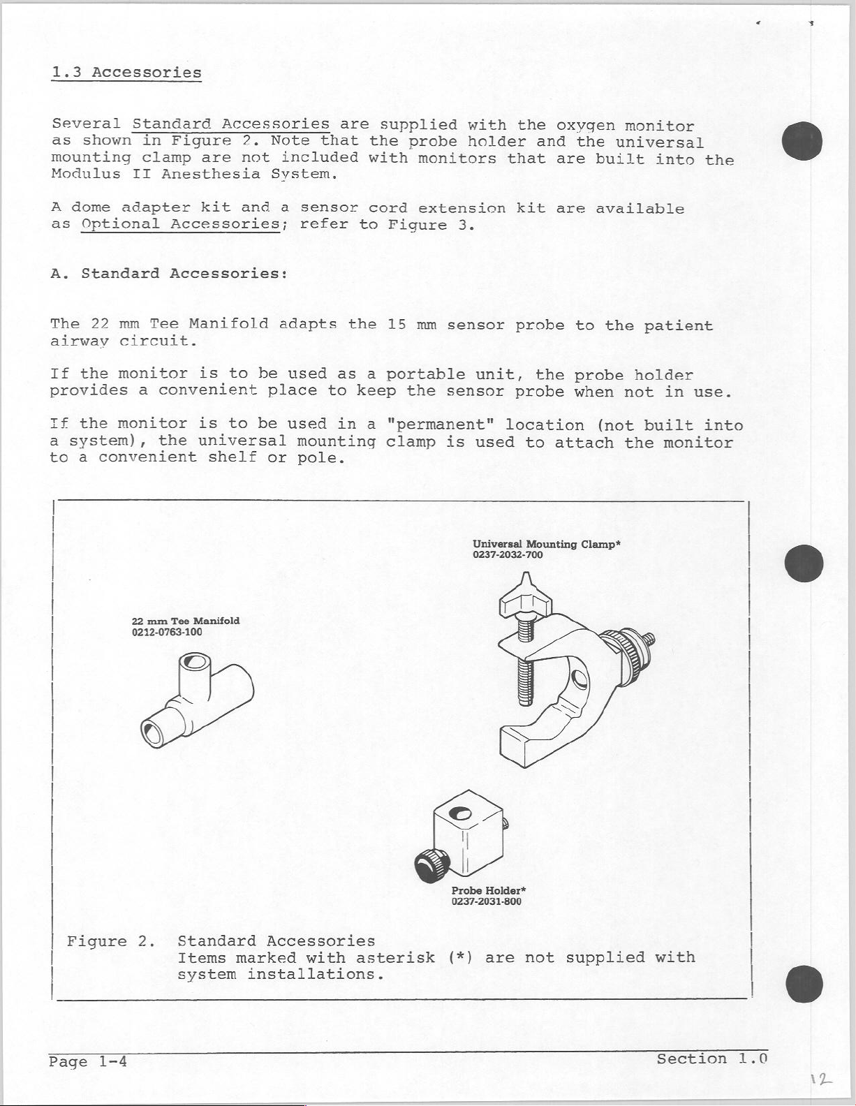
Several
as
shown
mounting
Modulus
A
dome
as
Optional
A.
Standard
The
22
airway
If
the
provides
If
the
a
system),
to
a
convenient
Standard
in
Figure
clamp
Anesthesia
II
adapter
Accessories;
Accessories:
mm
Tee
circuit.
monitor
a
convenient
monitor
the
Accessories
2.
are
not
kit
and
Manifold
is
to
is
to
universal
shelf
Note
included
System.
a
adapts
be
used
place
be
used
or
are
that
sensor
refer
the
as
to
in
mounting
pole.
supplied
the
with
cord
to
Figure
15
a
portable
keep
a
"permanent"
clamp
probe
monitors
extension
3.
mm
sensor probe
the
sensor
is
with
holder
that
unit,
location
used
the
and
kit
the
probe
to
oxygen
the
are
built
are
available
to
probe
when
(not
attach
monitor
universal
into
the
patient
holder
not
built
the
the
in
use.
into
monitor
22
mm
0212-0763-100
6)
Figure
2.
Tee
Manifold
©
Standard
Items
system
Accessories
marked
installations.
with
asterisk
Universal
0237-2032-700
Probe Holder*
0237-2031-800
(*)
are
Mounting
not
Clamp*
.
supplied
with
Page
1-4
Section
1.0
는
Page 13
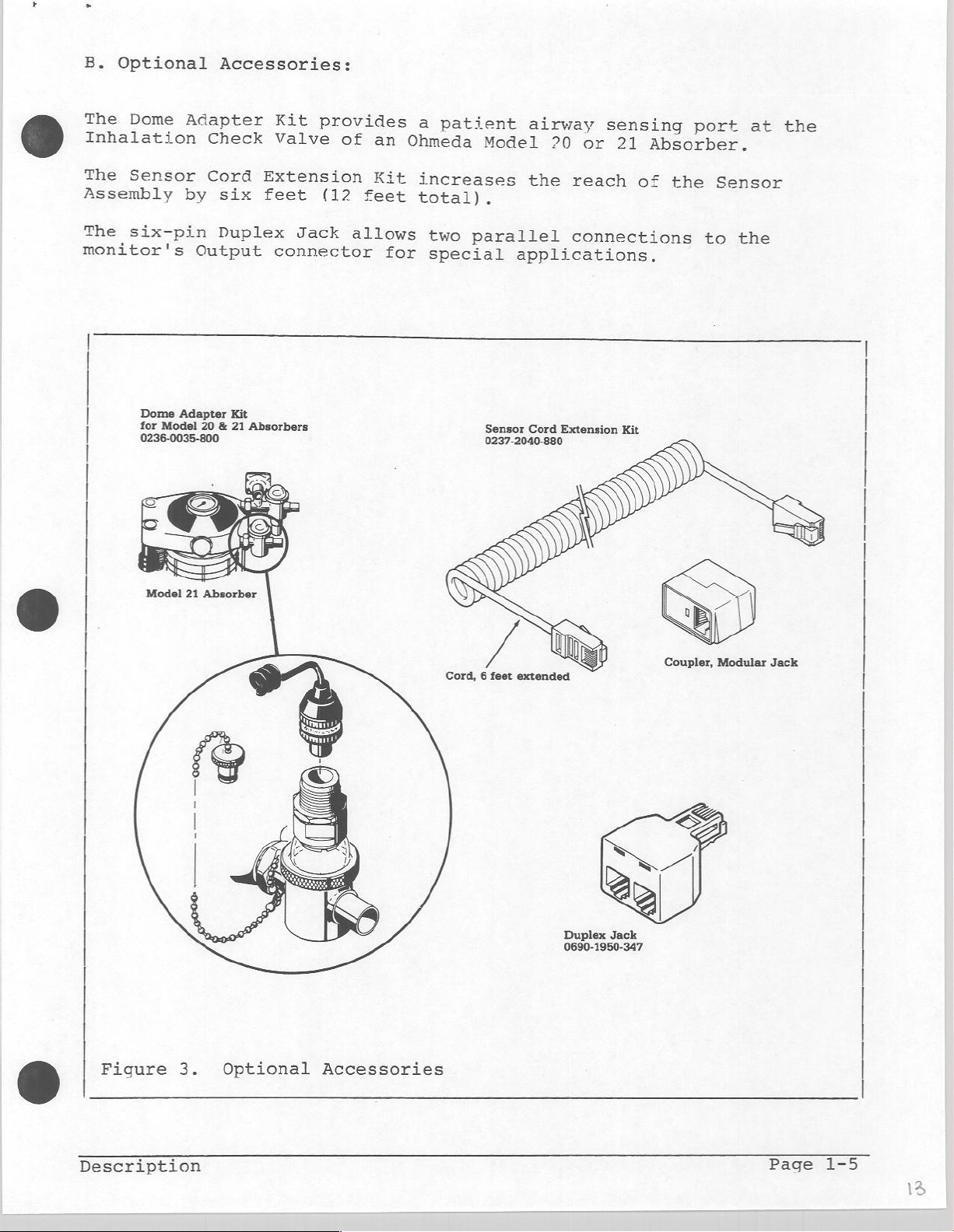
B.
Optional
The
Dome
Inhalation
The
Sensor
Assembly
The
six-pin
monitor's
Dome
for
0236-0035-800
Adapter
by
Adapter
Model
Accessories:
Check
Cord
six
Duplex
Output
Kit
20 & 21
Absorbers
Kit
provides
Valve
Extension
feet
connector
(12
Jack
of
feet
allows
an
Kit
for
a
patient
Ohmeda
increases
total).
two
special
airway
Model
parallel
Sensor
0237-2040-880
20
the
applications.
Cord
sensing
or
21
reach
connections
Extension
Kit
port
Absorber.
of
the
Sensor
to
at
the
the
Figure
3.
Optional
Accessories
Cord, 6 feet
extended
Duplex
0690-1950-347
Jack
Coupler,
Modular
Jack
Description
Page
1-5
Page 14
1.4
Specifications
NOTE:
and
Unless
subject
Performance
These
specifications
calibrated
DISPLAY
RANGE:
DISPLAY
DISPLAY
RESPONSE
DRIFT
MONITOR
RANGE:
otherwise
change
to
Specifications:
as
detailed
TYPE:
RESOLUTION:
UPDATE:
TIME,
LINEARITY:
TYPICAL:
indicated,
without
are
valid
in
LCD
0
1%
3
90%
in
+/-
+/-
notice.
section
(Liquid
to
100%
of
full
times
of
less
1%
1%
only
a
total
than
over
of
all
specifications
if
the
3.0.
Crystal
Oxygen
scale
second
change
20
an 8 hour
full
scale
monitor
Display)
reading
in
seconds
oxygen
at
period
are
is
properly
concentration
25
°C
nominal,
(77
°F)
¡RATING
‘ANGE:
TEMPERATURE
COMPENSATION
SENSOR
LIFE:
TEMPERATURE
RANGE:
#5,
+15"
12
months,
equal
°C
°С
to
to
о
+40.
+240
typical;
50%
-σ
at
26
(41
(59
+25
orton
SE
assumes
°C
(+77
to
104.
104
average
°F)
2m)
Е)
%
O2
Page
1-6
Section
1.0
Page 15

ALARM
-
VISUAL
SYSTEM:
=
Alphanumeric
out
Alphanumeric
BATT
Continuously
indicators
determined
of
OK
messages
selected
messages
and
LOW
(red
by
lit
alarm
limits:
BATT.
or
intermittently
or
yellow
condition.
indicating
HIGH
O2
indicating
Light
oxygen
and
LOW
battery
flashing
Emitting
concentration
O2.
condition:
alarm
Diodes
-
LEDs)
AUDIBLE
-
ALARM
ALARM
LESS
18%
SILENCE
THAN
LIMIT
一
一
Oscillating
continuous
intermittent
3-beep
determined
==
For
for
For
silenced
Silencing
duration
Setting
three
physically
alarm
of
Note:
Rev.
Low
30
conditions
(LED)
to
beep
(yellow).
whenever
the
For
3.0,
two-tone
low
low-tone,
by
02
condition,
seconds,
for the
an
remain
of
the
the
Low
tones
Although
set
low
limit
monitors
the
(2
tone
low
alarm
only.
other
alarm
lit
alarm
02
(1
tone,
condition.
the
than
duration
causes
continuously
period.
alarm
and
a
the
to
below
the
02
level
switch
with
alarm sounds
kHz/1
kHz),
kHz),
or
a
audible
Low
02,
of
the
any
flashing
limit
continuously
Low
02
alarm
18%,
setting.
software
the
falls
when
alarm
the
alarm
(not
below
monitor
below
revisions
oxygen
alarm
condition.
alarm
flashing)
18%
lit
limit
falls
can
results
alarm
can
issues
18%,
prior
be
silenced
can
be
indicator
for
in
indicator
be
a
regardless
to
below
the
LOW
10%.
02
POWER
DRAIN:
BATTERY
BATTERY
ANALOG
DIMENSIONS:
WEIGHT:
Description
REQUIREMENTS:
LIFE,
TEST:
OUTPUT:
NOMINAL:
Three,
Typical
(assumes
1300
hours
size
current,
hours;
a
day);
backlight)
Manual
10
load
Depth:
Width:
Height:
0.6
and
mV/%02
impedance
kg
(1.3
C,
no
alarms
eight
Automatic
at
6
cm
9
cm
17
cm
alkaline
3.5
weeks
(assumes
10 K ohms
(2.25
(3.50
(6.75
lbs)
without
milliamps
or
use
no
minimum
inches
inches
inches)
batteries
of
backlight)
continuous
alarms
sensor
at
or
4.5
use
use
volts
(24
of
Page
1-7
Page 16

Alarm
‘Alarm
a
Sensor
Assembly
[—]
e
Power
(7
com
toa
OP
quinti
Sensor
input
πρ
Substitute
Circuit
©
Alkaline に ~
Alarm
Circuit
dim
n
ee
External
>
t
mener
me
E
+SV|
le
Bram
=
©
Switch
Darty
Backlight
|
HOT
E
Gircutry
Am
Indicatore
LEDs
~
^"
ES
mm
Figure
4.
5120
Oxygen
Page
1-8
Monitor,
Block
Diagram
Section
1.0
Page 17

2
+0
THEORY
OF
OPERATION
This
the
with
board
manual
operation
functional
(Control
boards.
(output)
functions
The
relationship
described
and
Power
Converts
to
a
plus
Microcomputer
Controls
(except
LCD
Display
Converts
to
its
Backlight
Improves
assumes
of
-
The
theory
or
which
the
of
in
Supply,
for
Circuits..
battery
5
volt
all
operations
watchdog
. .
digital
alphanumeric
<
display
that
microprocessor
circuit
Display)
blocks
discusses
the
circuits
monitor.
between
following
the
power
and
a
. .
0...
timer
.
eee.
information
eguivalent.
-©
visibility
the
or,
these
„.
(or
minus
of
reader
controlled
located
in
signals
use
blocks
list.
.
-
power
5
the
).
from
He.
in
some
(input)
.
(section
from
volt
(section
monitor
(section
(section
low
is,
in
on
one
cases,
which
is
shown
an
supply.
the
microprocessor
ambient
general,
systems.
or
split
the
circuits
to
achieve
in
2.8).
external
2.2)
2.3)
2.4)
. .
...
si
light.
The
the
between
Figure
. .
source)
familiar
theory
other
generate
the
4
...
- - *
>
<<.
vo
with
deals
circuit
the
two
various
-
-
Page
Dage
. - Page
nt
page
2-3
2-4
2.0
2-8
Front
Low
(For
Sensor
Converts
oxygen
A/D
Converts
Converts
analog
Alarm
Generates
microprocessor,
Watchdog
Issues
is
Al'arm:
Alarm
Analog
Produces
for
Panel
02,
High
Batt
Input
the
concentration)
—
D/A'Converter
the
digitized
equivalent
and
Timer
an
sensed.
Output...
output
θαεραὲ.
a
remote
Power
Alarm
audible
alarm
Switches...
02,
Batt
On/Off
. . .
input
sensor
Indicators
alarms
2perator
. .
condition
for
remote
ον
voltage
monitoring.
Test/Backlight
from
refer
as
the
to
sensor
to a proportionally
»
.*.*.'...
voltage
oxygen
(D/A)
. .
to
concentration
for
remote
. .
and
visual
and
"Watchdog"
igor
om
if a system
i
+...
+ -
monitoring
ο
proportional
ος.
(section.
DO,
section
(Section
(current
(section:
its
digital
2.1.)
value
monitoring
(section
alarm
circuit
(section
(monitor)
(section2.10);
(section
to
the
oxvgen
2.5).
Circuit
2.6)
proportional
varying
257).
»
equivalent
to
(Analog
2.8)
. . . . . . .
indicators
2.9)
2.11)"
Lo.)
concentration
Test.
..
voltage.
cd)
its
inputs.
failure
..
.:.
© ©
IP
. .
to
cm
(A/D).
Output).
based
.—
48.
on
-
こら
Раде
Page.
Page
page
bage
bage
ンー
ニン
2-10
212
2-14
2-15
216
2.18
Theory
of
Operation
Page
2-1
Page 18

CRIOT
5082-2835,
ч.5У
BAT.
PACK
|
ts
91006
ICLIGLO
Sp
y
ν
で
10
II9
tte
Hle-
Cte
10
sE
二
τ
сит
山
說 -5
| * Note:
|
Figure
Page
2-2
This
the
directly
5.
Power
10
ohm
junction
to
Supply
resistor
of
L101
pin
3
Circuit
of
may
and
U101.
be
present
CR107
is
in
some
connected
units.
If
not,
Section
2.0
Page 19

2.1
Power
To
operate
Since
voltage
considered
the
voltage
The
DC-DC
regulator.
by
connecting
regulator.
(R103/R104),
around
which
L101
is
capacitor
above
to
the
the
recharge
specified
Supply
properly,
monitor
can
vary
discharged,
to
the
converter
The
When
to
added
C108
fixed
the
required
circuit
it to
the
the
collapse.
to
through
reference,
inductor.
+5
Circui
the
is
powered
from
4.5
is
a
designed
builds
ground
output
transistor
the
applied
diode
volt
output.
monitor
volts
DC-DC
level.
through
voltage
switch
The
the
This
requires
by
batteries
when
power
around
fresh
converter
up a magnetic
a
transistor
falls
opens
collapsing
voltage.
CR107.
transistor
process
When
U101
below
causing
field
The
the
is
a
constant
whose
to
3.0
(RC4192),
field
a
generates
higher
output
switch
repeated
combined
volts
is
used
in
switch
fixed
the
voltage
voltage
is
again
rapidly
+5
volt
terminal
when
to
boost
a
switching
inductor
in
the
value
magnetic
a
voltage
charges
turned
supply.
rises
to
the
L101
4192
field
on
maintain
Diode
power
Schottky
CR107
supply.
Resistor
are
inadvertently
Some
are
include
items
connected
indicators.
addition
In
operational
the
voltage
volt
-5
is
type
R105
in
the
backlight,
to
converter
supply.
a
Schottky
Regular
diode
and
the
conducts
diode
installed
monitor
directly
+5
the
amplifiers
which
diode
silicon
CR106
do
to
the
the
volt
converts
used
diodes
at
about
protect
backwards.
not
switched
audible
supply,
and the
to
conduct
the
require
alarm
negative
a
D/A
+5
the
improve
0.2
volts.
system
a
regulated
power
circuits,
converter.
volts
the
at
about
if
input
voltage
applied
efficiency
0.6
the
voltage.
(Vs).
and
the
is
Component
to
volts.
batteries
Thev
These
LED
required
U106
to
it
of
the
The
items
alarm
for
is
a
a
Theory
Operation
of
Page
2-3
Page 20

2.2
Microcomputer:
Component
146805
memory
software
programmable
Figure
Figure
Microprocessor
Power-on
handled
the
external
connected
line
reset
momentary
(as
is
rapidly).
Components
and
power supply.
supplv
drops
0105
0104,
the
-
ROM);
(RAM)
program,
6
shows
7
lists
by
microprocessor.
circuitry
insures
occurs
when
turned
C115 form
microprocessor.
voltage
by
turns
forcing
the
more
U102
for
timer.
reset
circuitry
to
the
that
during
power
power
off
CR114,
on
which
is
it
the
the
Reset
is
cycling
and
a
small
If
(+5
than
a
reset
a
CMOS,
is
a
storing
32
I/0
microprocessor's
function
normally
in
The
RESET
proper
switch
on
C123,
the
main
volts)
1.2
turns
single-chip
complete
variables,
lines
volts,
on
of
of
computer
for
input/output
each
|
|
|
トー
|ÆRIAG,R
1
1
1
1
1
1
1
1
microcomputer
system
fixed
external
I/O
Rain
port.
EPROM
vió
1432
memory
VERSION
MES
JUMPER
(1468705
containing
(EPROM
functions,
connections.
=
|
or
a
ls
Elo
lu
3k
hos.
可。
lu
1400705.
al,
trom
ai
140805
«Rom
-
EPROM
random-access
ROM)
and
for
a
싸는
ME
A
She
시트
ae
we
~
mf
or
ep
|
or
the
|
1
|
|
|
Page
2-4
Figure
6.
Microcomputer
Section
2.0
Page 21

output
output
input
input
output
output
output
output
input
input
input
input
output
input
output
output
output
output
output
output
output
|
65
cé
CT
output
output
output
D/A
bit
D/A
bit
Sensor
Battery
Analog
Analog
Analog
Analog
Bit
0
of
of
1
Bit
of
2
Bit
of
Bit
Yellow
3
External
Watchdog
Alarm
D/A
D/A
D/A
D/A
or
D/A
or
D/A
or
D/A
or
D/A
or
output,
bit
bit
bit
bit
selects
bit
selects
bit
selects
bit
selects
bit
selects
8
9
voltage
voltage
switch,
switch,
switch,
switch,
BCD
BCD
BCD
BCD
LED;
Alarm
Timer
つの
3,
ων
input
4,
LSD
5,
MSD
6,
LSD
7,
MSD
comparator
comparator
connects
grounds
connects
to
sample/hold
switch
switch
switch
switch
on,
is
1
Silence,
output
1
=
switches
of
of
of
of
sensor
input
reference
amplifier
inputs
inputs
inputs
inputs
is
0
rising
alarm
low
low
high
high
condition
limit
limit
limit
limit
output
output
to
off
$201,
to
amplifier
amplifier
voltage
edge
exists
S202
tricaered
「
output
output
output
output
output
input
output
output
output
Figure
Theory
of
Input/Output
7.
Operation
Clock
Data
Switch
Strobe,
Switch
External
Red
Oscillator
Tone;
for
to
for
for
LED;
0
Ports.
display
display
comparators;
latches
backlight;
supply
1
is
on/off
152
on,
kHz,
shift
shift
data
sense
0
control;
Ii
register
register
0
is
into
is
às 1 kHz
0
shift
is
off
on,
off,
0
is
1
is
register
1
is
on
off,
1
off
is
outputs
on
Page
2-5
Page 22

2.3
LCD
The
oxygen
indicates
100
and
The
100
(%),
LOW
display
Hz.
frontplane
turned
backplane
applied
zero
off
will
display
Display
monitor
oxygen
and
02.
is
A
segment
is
by
voltage.
across
cause
and
eventually
four
driven
out
having
the
the
uses
(02)
status
is
of
A
LCD
internal
a
custom
concentration
messages;
with
turned
phase
the
square
a
with
frontplane
is 0 volts.
cause
Liquid
5-volt
on
when
the
wave
is
chemicals
the
display
Crystal
as
a
BATT
OK,
square
the
voltage applied
backplane
voltage
used
Any
voltage
to
number
wave
so
plate
to
Display
between
LOW
BATT,
at a frequency
voltage.
in
phase
the
average
component
the
fail.
HIGH
to
A
with
voltage
inside
(LCD)
00
and
02,
the
segment
the
other
of
that
of
than
the
E
is
A
24-bit
display.
(100
Components
The
malfunction,
Hz)
enable
the
watchdog
Backplane
shift
Data
and
U201,
pin
register
is
stored
of
timer
it
pulls
shifted
in
U202
the
On
CT
with
into
the
and
U203
shift
circuit
the
enable
=
output
the
output
are
registers
(refer
latches
register
latches.
CMOS
to
pins
shift
is
normally
section
"low"
Off
is
used
every
registers.
to
blank
to
10
milliseconds
held
2.9)
drive
"high".
senses
the
display.
the
©
a
Page
2-6
Section
2.0
Page 23

Fels
引
F
DE
34
uj
alal
U203
4094
A
|
De
nas
=
e
su
ия
A
2
DATA
Py
swrreock
LATCH
STROBE
a
Заз
Br
VIOZ
À
|
P
33
μὴ
Uzol
4094
|
E
ol
эт
Y
οἱ
9
de
pa
са
|
fer
sl
3]
L
o
al]
M9
a
|:
le
BL
si
A
ale}
À
ue
1
Ss
EN
Eb
의
м
U?202
4094
더
=e
기
11
이이
ST
k
ç
=
C
31
]
pa
의
ale
la
は
all
w
G
ail
15
Ее
ode,
Esso
53
Side
αἱ
αἱ
ο)
1
“5
ドコ
la
EN
=
d
Figure
8.
LCD
Display
ENABLE
WARM
DOG
FROM
TIMER
Theory
of
Operation
Page
2-7
Page 24

vs
Figure
|
9.
Dszoi
EL
PANEL
Backlight
E)
x
τζοι
?
AD
CRIOI
FROM
V
EXT
3203
@
©
2.4
Backlight
The LCD
to
improve
bv
a
DC-AC
the
microprocessor
The
inverter
batterv
battery
If
the
Anesthesia
causina
Port
external
the
D4
BATT
display
visibility
inverter
supply
to
reduce
monitor
System),
the
the
of
supply
OK
is
produces
(VS).
the
is
externallv
EL
panel
microprocessor
sense
message
backlit
in
(T201)
through
about
Power
current
the
to be
input.
will
by
low
ambient
The
transistor
80
for
powered
external
on,
If
be
not
an
electroluminescent
light.
inverter
Vrms
the
inverter
load
also
on
voltage
continuouslv.
functions
external
an
displaved
is
0201.
at
400
the
(installed
The
EL
panel
controlled
Hz
from
comes
power supplv.
at
CR201
periodically
supply
during
the
directly
in a Modulus
forces
battery
a
(EL)
by
detected,
is
panel
is
driven
port
switched
from
0201
as an
test.
(DS201)
D4
of
the
II
on
Section
2.0
Page 25

ce
+5
E
Autos
100K
B3
,
ANIL
uloz
P
F
|
>
BI
ao
as
400K
5
400K
4001
100K
RN401
RMOt
i
1
1 1 1 ㅣ
т
1 に
1
I
1 1 1 + 1
1
i
|
i
À
1
A |
LO
02
MSD
STROBE
To
ie
し
で
1
ne
απ
v
ili
站
1002
LINES
D/A
CONVERTER
に
<
in
1 1
Teens
T
hel
Ea
1
C
i |
LSD
1
te!
し
<
T
1
nr
lest
Jů
Oe
lei
at
1
el
156
HIGHOZ
т
MSD
GR402
a
i
1
απ
må.
πα,
T
leet
1,
jar
i
ns
ii
1
r
μη
+
ЕЯ
HIGHO2
LSD
CRIOU
к
rol
5
cam
5202
ALARM
cR10
BATTERY
TEST
ser
CIRCUIT
TEST
68109
SILENCE
Figure
2.5
Front
Operator
(for
Circuit
BCD-encoded
The two
pushbutton
The
switches
microprocessor
one
row
diodes
The
switch
Note
and
the
function
or
the
10.
inputs
High
Test)
test
of
is
that
Digital-to-Analog
is
digitial/analog
Front
Panel
Ο2
and
and
thumbwheel
switches
switches.
are
switches
are
closed.
the
output
activated
Panel
Switches
to
the
oxygen
Low
02
an
alarm
switches,
and
connected
output
used
lines
and
eliminate
to
lines
at
converter
L
Switches
monitor consist
alarm),
silence
alarm
in a matrix
(C3
inputs
(C2
converter.
time,
a
am
munewmet
two
each
silence
to
their
false
to
either
is
test
switch.
having
C7).
status
C7)
This
being
sunrcu
switches
switch
and
The
readings
are
shared
works
the
used.
αἱ
of
two
(Batt
The
two
limit
8
output
are
momentary
scanned
microprocessor
(BO
to
R3).
when
between
because
switches
limit
Test
switches
connections.
(strobed)
more
are
than
the
only
being
switches
and
bv
the
selects
one
switches
one
scanned
are
Theory
Operation
of
Page
2-9
Page 26

2.6
Sensor
The
sensor
to
the
is
converted
and
R126.
The
output
the
developed
operator
The
sensor
temperature
circuit.
The
resistor
When
oxygen
With
the
when
the
oxygen
This
to
sensor
fixed
Input
produces
concentration
to
a
voltage
current
voltage.
compensate
also
contains
variations
divider
is
the
sensor
gain
Circuit
a
voltage
from
network
outputting
of
current
by
is
about
the
External
for
the
a
thermistor
(J104-5).
is
new))
27,
the
(J104-4
at
its
a
resistor
sensor
reduced
feeds
46
output
detecting
46
millivolts
decreases
control
The
resistor
into
mV
(the
the
divider
/
3104-3)
network
R140
output.
to
compensate
an
approximate
from
which
surface.
consisting
for
with
(CAL pot)
R122
amplifier
network
the
amplifier
100%
age,
the
is
is
is
This
oxygen.
thereby
is
circuit
part
with
value
set
proportional
current
of
R140
reducing
used
by
for
of
this
a
gain
for
at
of
100%
80%.
is 1 volt.
@
the
27.
The
The
as
and
A
sensor
cell
sensor
the
system
described
reference
13)
positive
(3104-6)
ensure
Components
protection
circuit
The
present
the
for
that
contains
is
input
to
measure
further
(Pins
the
offset
the
R112,
of
the
consisting
sensor
two
connected
circuit
6, 8,
Circuit
voltage
offset
CR117
sensor
(Stock
the
in
and
will
and
of
cells.
to
includes
offset
section
9)
Test
is
be
CR118
input.
U110,
Number
To
load
of
2.7
instead
mode.
injected
positive
provide
R127,
0237-2034-700).
prevent
resistor
analog
the
or
of
into
R128,
oxide
R144.
switches
amplifier
to
connect
the
sensor
the
and
thus
electrostatic
and
build-up,
(U109)
(Pins
a
fixed
(Pins
amplifier
can
R139
which
3,
1,
via
always
discharge
not
are
the
unused
4,
and
voltage
2,
R131
be
used
allow
5)
@
to
measured.
with
Page
2-10
Section
2.0
26
Page 27

EXTERNAL
a
(Se)
aDe
a
SUPPLY
SENSOR
3104
ο
vio
Jers
ο
PRESENTLY
E
INPUT
$
m
I
ven
R
LE
wate
Pan
fd
s
NOT
USED
Figure
Theory
11.
of
Sensor
Operation
Input
Circuit
Page 28

SENSOR
A6
azla
A3
vio?
P
7
AT
AMP
Ay
mp
ale
AG
οτι
ce
cs
cu
caps
cole
cia
colza
>—
8
區
トビ
로
1.2 V REF,
=
ES
Ta
vo
“lps
ES
sb
ize
zs
中
Sp
123
ul
ala
Ba:
Boo
Rr
om
ола
мо
VA
VRE
via
ADJ.
91.5
0129
482K
1.5"
lu
i
Las
|.
=
АНА
GND
15
I
TP
TO
-1.138V?
К1%
1%
53
SISTE
GND.
Ri38
ce
dona
.003V
gro
100
ss
“+
po
sy
3]
9107
grist
=
yea
Yı
Por
f
as
took
p
=
Figure
Page
12.
2-12
Digital-to-Analog
Converter
Section
2.0
Page 29

2.7
D/A - A/D
Converter
2
The
digital-to-analog
performs
described
converter
Integrated
a
current
input
a
voltage
1.138
The
The
The
reference
reference
reference
output
two
in
as
which
terminals.
by
volts.
diode
comparators
sensor
The
amplifier
outputs
microprocessor
The
microprocessor
to
convert
10-bit
digital
functions:
section
described
Circuit
U104
is
proportional
The
amplifier
voltage
(VR102)
voltage
of
the
D/A
(U107).
from
One
and
each
(U102).
uses
the
battery voltage
number.
converter
it
2.11
and
here.
is
output
U105.
(U104-15)
and
(Vref)
converter
comparator
the
other
comparator
a
"successive
(U104
generates
is
a
10-bit
to
current
The
output
is
an
adjustment
is
set
(U105-7)
comparator
are
or
the
part
CMOS
the
of
generated
to
measures
connected
the
and
its
associated
analog
of
the
analog-to-digital
D/A
converter
digital
the
D/A
voltage
by
resistor
-1.138
is
volts
connected
the
measures
approximation
sensor
amplifier
output
value
unit
range
a
fixed
voltage
to
inputs
voltage
that
present
is
converted
is
voltage
(R138).
(section
to
from
battery
conversion
voltage
circuitry)
as
produces
at
from
two
0
3.3).
voltage
the
voltage.
on
the
routine"
to
its
to
to
a
©
Resistors
outputs
To
minimize
powered
is
turned
and
turned
Auto-Zero
The
"auto-zero
voltage
sensor
(using
sensor output
output,
determine
into
the
the
offset
R118
to
when
on
Logic
of
voltage.
U109,
and
the
inverting
help
power
the
when
off
when
the
switch
to
finally,
sensor
is
always
and
R121
eliminate
drain
conversion
the
completed.
logic"
sensor
The
microprocessor
A)
the
input
provide
oscillations.
on
the
analog
is
a
software
amplifier
and
measures
amplifier
subtracts
voltage.
of
positive.
a
batteries
routine
to
digital
(U111)
(using
the
A
negative
the
amplifier
slight
is
routine
grounds
the
offset
hysteresis
the
in
software
and
offset
U109,
offset
comparators
effect.
that
subtracts
the
input
voltage,
switch
from
via
the
R131
to
Transistor
routine
measures
it
of
B)
output
voltage
to
the
are
is
the
from
the
connects
and
measures
voltage
is
ensure
comparator
only
Q106
executed,
offset
the
amplifier
the
the
to
injected
that
Theory
of
Operation
Page
2-13
Page 30

vs
do
CRION
Figure
2.8
Audio
+
È
2
È
13.
Alarm
Alot
AUDIO
Audio
ALARM
and
A
te
our
em
τοι
102.
Alarm
Alarm
U103
7555
RESET
=
y
E
åg
Se
6101
η
3
[u
b
y
k
立
em
and
Alarm
Indicators
ENABLE
is
18-
203
Bi
ek
L_<
Indicators
πιο.
зол.
A
RED
am
FROM
WatcHDOG
TIMER
ALARM
OUTPUT
e
Rio
ES
Ro
100K
Rio8
AN
took
2105
a
BY
pe
UIOZ
DT
上
E
Audio
The
and
or
lower
resistors
The
Variable
The
Diode
by
LED
The
The
The
or
Power
current
Alarm:
monitor's
an
2
kHz.
frequency
frequency
transducer
CR101
the
Alarm
red
red
yellow
the
for the
audible
oscillator
The
oscillator
R111
is
resistor
across
inductive
Indicators:
and
yellow
LED
is
LED
watchdog
LEDs
load
on
(U103)
of
and
doubled
R137
is
driven
load
driven
is
driven
timer
the
the
R137
the
LEDs
comes
power
alarm
that
is a CMOS
oscillator
and
by
is
used
by
transducer
of
the
are
by
0202
by
in
case
directly
supply.
consists
can
capacitors
disconnecting
to
FET
Q103
transducer
located
via
9203
via
of a microprocessor
of
an
generate
version
is
set
C110
tune
eliminates
port
from
from
on
port
the
when
the
D5
the
audio
a
tone
of
the
by
the
and
capacitor
lower
the
output
the
it
alarm
of
the
B4
of
battery
transducer
of
either
555
timer.
RC
time
C111
frequency
voltage
is
turned
silence
microprocessor.
the
failure.
to
constant
(through
C111
of
the
microprocessor
reduce
(A101)
1
The
(0102
to
oscillator.
spike
off.
switch.
the
kHz
of
Q102).
open).
1
kHz.
generated
Page
2-14
Section
2.0 5
Page 31

ENABLE
DISPLAY
LINE
SHIFT
TO
REGISTERS
Figure
2.9
Watchdog
14.
TONE
το
AUDIO
FREQUENCY
Watchdog
Timer
To
AUDIO
cruz
ji
a
İİ
|-u
E
Timer
3
|
|->
9
TO
LED
F1
Е
A
RIOT
ve
ーーーー
T
テ
YELLOW
|
R108
+
cio
ol
TO
ALARM
ουτρυτ
ne
look
é
næ
Rio&
一
ww
AOL
190K
jee
WT
一
60
May
Do
책
一 3
yr
102
ye
The
watchdog
running
outputs
capacitively
which
keeps
If
(R107)
display
activates
CR112-1
CR112-3
CR112-2
CR112-4
the
charges
0101
processor
will
due
to
a
square
turned
discharge
enable
the
pulls
turns
selects
turns
timer
coupled
the
associated
the
on
on
circuit
some
wave
load
off
stops
lines
remote
the
the
the
error.
of
(C107)
capacitor
and
operating
capacitor
low
yellow
low
(1
audio
is
The
about
to
the
to
blank
alarms
Alarm
LED
kHz)
alarm.
used
display
to
processor,
50
Hz
a
diode
(C106)
for
C106
the
through
Output
alarm
audio
detect
when
on
port
rectifier
to
enable
some
turning
reason,
display.
isolation
line
indicator
tone
when
B6.
about
lines
0101
low
(see
the
operating
This
circuit
5
volts.
high.
the
on
When
(see
turned
diode
section
(see
section
processor
correctly,
square
(CR108/CR113)
The
load
and
pulling
pack
section
2.8).
stops
wave
voltage
resistor
on,
0101
CR112.
2.10).
2.8).
is
the
Theory
Operation
of
Page
2-15
Page 32

FROM
WATCHDOG
TIMER
ALARM
OUT
Mode
3103-3
"a
10K
uloz
PP
87
ALARM
EXT
|
Figure
2.10
When
watchdog
about
static
Refer
When
When
pulses
conditions
sent.
low.
OUTPUT
Alarm
an
1
discharge
to
no
an
corresponding
When
This
when
15.
Output
alarm
timer,
mA
of
Figure
alarm
alarm
are
pulses
allows
SILENCE
Jr03-4
individual
Alarm
condition
the
drive
protection,
16,
condition
condition
prioritized
are
a
+5
ne
=
Output
ALARM
current,
Figure
to
not
simple
alarm
태조.
WOK
is
detected
OUTPUT
17,
exists,
occurs,
the
alarm
so
being
alarm
+5
CRile
имам.
crus
14914
line
while
and
ALARM
ALARM
condition
that
transmitted,
indicator
decoding
by
is
CR119,
Figure
OUTPUT
OUTPUT
only
is
the
microprocessor,
pulled
CR120,
18.
is
emits
which
the
highest
ALARM
to
be
not
necessary.
"|:
low.
high
connected
and
a
exists.
priority
OUTPUT
U108
R123
(>
series
or
provides
provide
4.5
Alarm
remains
to
by
volts).
of
10
code
ALARM
the
ms
is
logic
External
An
input
connected
alarm
The
maintain
A
allowed.
Page
input
maximum
2-16
just
Alarm
is
provided
between
as
is
an
alarm
input
Silence:
pin
the
"alarm
high-to-low
silence.
voltage
for
4
remote
and
pin
silence"
sensitive,
The
of
5.5
alarm
3,
switch
input
volts
silencing.
when
closed,
on
the
a
continuous
is a transient-protected
and
a
minimum
A
normally
will
front
low
of
silence
of
the
input
-0.5
open
the
monitor.
will
CMOS
volts
Section
switch
audible
not
input.
are
2.0
Page 33

Number
Pulses
of
Alarm
Condition
Priority
Figure
16.
二
2
3
4
>
6
Remote
1)
Alarm
H
Lo
а,
2)
Alarm
H
£
pt
LOW
HIGH
"00"
Discharged
Low
LOW
Alarm
condition
トー
10
msec
condition
See
02
02
BATT
Pulse
begins
|
exists
LS
02
202
displayed
limit
Code
320
batteries
<
18%
msec—_________»
m
στ
3
1
2
3
4
Di
6
nr)
10
msec
3)
Alarm
H
L
Figure
|
Figure
17.
J103-6
Alarm
J103-3
Signal
18.
Alarm
Output
GND
Alarm
condition
Output
a
Interface
200
τα
1-shot
ends
Waveforms
msec
—i
ale
RDY
Circuitry
=
EN
CLK
Counter
Qa
Qb
| |
Alarm
Qc
Codes
Reset
Auf
一
10k
一
Theorv
of
Operation
Page
2-17
Page 34

TO
A/D
COMPARATORS
qe
M
U102
PP
ate
role
c
=
coli
csp
cale
cls
A
d
AT
vo
sl
do
ar
dat
25
о
1
re
E
VOA
ao
401533
ly
Reg
am
E
ола
ов
|
“
ADI
T0-1138V
=
TŽ
loo5
s
a
At
STEN
età
πι
5
Ces
*.003V
+5
=
に
pa
*-s
ANALOG
10
i
mV/%e
TFA
aus
AT
i
OUTPUT
Oz
,
Ji03-5
3,03-
J103-1
7103-2.
ANL
007
GND.
ANL
SHELD
gure
2.11
The
analog
with
The
microprocessor
converts
connected
switch
value,
buffered
at
the
is
updated
19.
Analog
the
input
to an
(U109,
the
by
monitor's
Output
output
to
the
switch
the
every
Analog
voltage
analog
switch
high
Output
consists
outputs
voltage
sample-and-hold
D).
is
opened.
input
Output
10
ms.
of a sample-and-hold
coming
When
jack
from
a
10-bit
(see
the
The
impedance amplifier
(J103).
the
section
capacitor
capacitor
voltage
D/A
digital
The
analog
converter
value
2.7).
(C113)
is
across
sample-and-hold
which
This
through
charged
the
(U105)
capacitor
register
(U104).
the
voltage
the
to
the
and
available
register
(U105)
D/A
is
analog
new
is
Page
2-18
Section
2.0
au
Page 35

3.0
TEST
The
oxvgen
specific
An
external
to
compensate
AND
CALIBRATION
sensor
concentration
calibration
for
is
the
an
expendable
of
control
decrease
oxygen
item
decreases
(CAL)
in
output
whose
is
provided
gradually
(21%
output
for
02
calibration).
current
with
the
for
time.
operator
a
Additionally,
must
the
The
whenever
checked
If
does
be
be
calibrated
linearity
monitor
whenever
the
monitor
not
corrected
CAUTION:
to
damage
work
to
using.
Use
at
a
discharge
Handle
an
anti-static
as
of
contains
the
monitor
function
before
This
monitor
by
electrostatic
static
accumulated
the
specified
to
the
the
cannot
as
control
circuit
container
"100%
oxygen
other
is
serviced
monitor
be
calibrated
specified,
returning
contains
workstation;
static
boards
in
the
Operator's
02",
at
sensor.
controls
or
does
not
a
malfunction
the
monitor
electronic
discharge.
charges
by
for
transport.
regular
which
whose
perform
or
if it
When
wear
from
their
Manual,
intervals,
must
calibration
to
be
calibrated
to
specifications.
can
be
is
indicated
clinical
components
disassembling
a
static
you
and any
nonconductive
the
monitor
to
verify
should
calibrated
which
use.
that
are
the
control
tool
edges.
be
but
must
susceptible
monitor,
wrist
you
strap
are
Test
and
Calibration
Page
3-1
Page 36
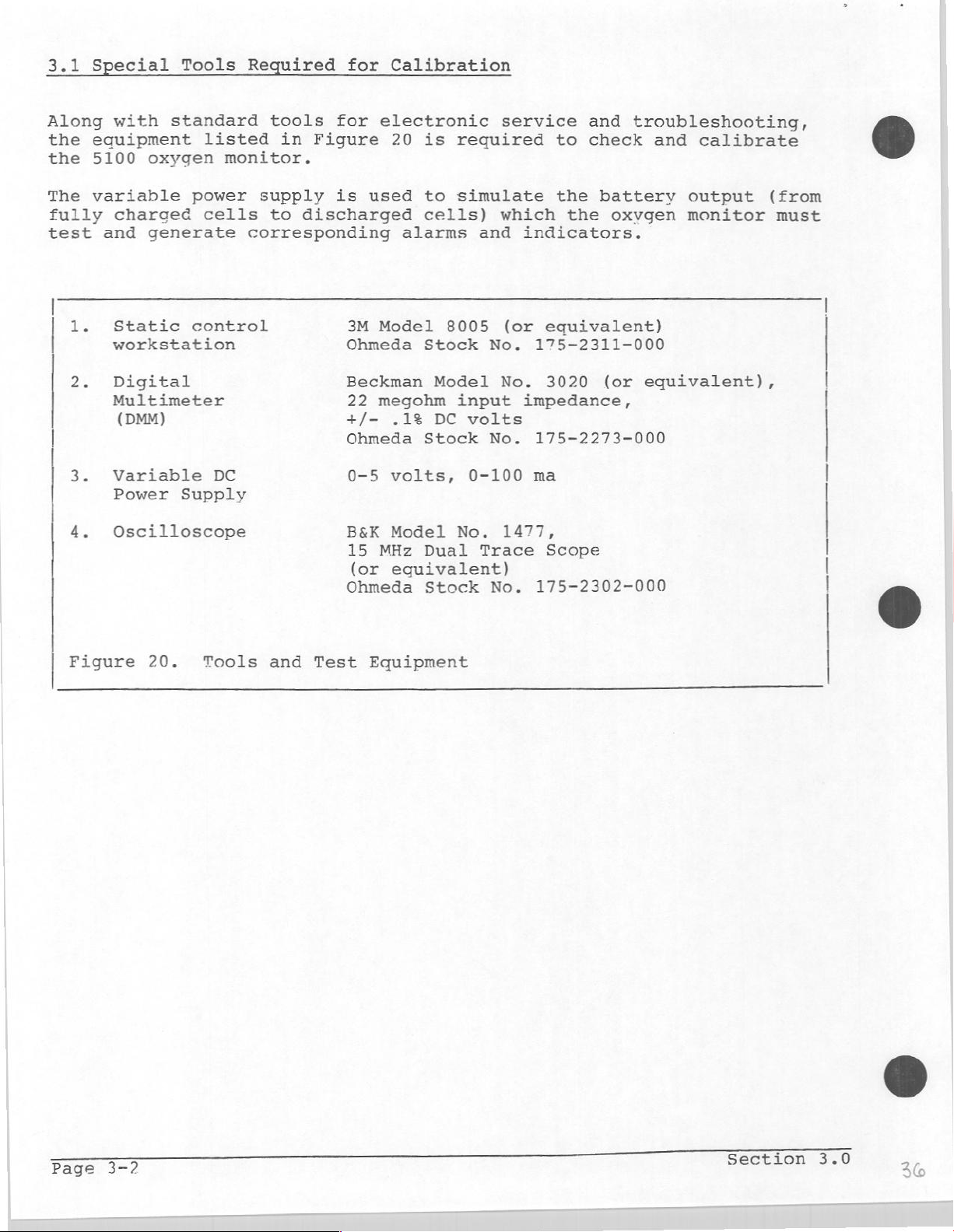
3.1
Special
Tools
Required
for
Calibration
Along
the
the
The
fully
test
1.
2,
|
|
3.
4.
with
equipment
5100
variable
oxygen
charged
and
generate
Static
workstation
Digital!
Multimeter
(DMM)
Variable
Power
Oscilloscope
standard
listed
monitor.
power
cells
control
DC
Supply
tools
in
supply
to
for
Figure
is
discharged
corresponding
3M
Ohmeda
Beckman
22
+/-
Ohmeda
0-5
B&K
15
(or
Ohmeda
electronic
20
is
used
to
cells)
alarms
Model
Stock
Model
megohm
.1%
DC
Stock
volts,
Model
MHz
Dual
equivalent)
Stock
required
simulate
which
and
8005
No.
No.
input
volts
No.
0-100
No.
Trace
No.
service
to
the
the
indicators.
(or
equivalent)
175-2311-000
3020
impedance,
175-2273-000
ma
1477,
Scope
175-2302-000
and
troubleshooting,
check
battery
and
oxvgen
(or
equivalent),
calibrate
output
monitor
©
(from
must
Figure
20.
Tools
and
Test
Equipment
Section
3.0
si
Page 37

3.2
Functional
Checkout
Procedure
Inspect
Inspect
Plug
applicable,
If
Note:
replace
repeat
1.
Set
a.
b.
c.
d.
2.
Press
Verify
and
3.
Press
Verify
4.
Press
the
the
the
If
the
this
the
The red
The
The
The
that
monitor's
sensor
sensor
during
batteries
procedure.
Batt
audio
BATT
display
and
that
the
and
that
and
assembly
turn
this
Power
and
yellow
tone
OK
message
release
the
backlight
release
backlight
hold
housing
the
and
into
Modulus
cord
procedure,
with
switch
sounds
indicates
the
BATT
the
OK
the
Circuit
housing
three,
LEDs
briefly.
and
a
GOD
message
turns
(XO
turns
and
Output/Sensor
Sensor
the
System's
II
the
size
to
On
flash
backlight
value
/Batt
on.
/Batt
off
Test
damage.
for
input
monitor
C,
alkaline
and
verify
briefly.
appear
for % 02.
Test
appears
Test
(BATT
switch
switch.
switch
OK
jacks
connector.
master
indicates
the
for
for
about
again.
message
and
verify
for
switch
LOW
batteries
following.
about
5
seconds
appears
the
damage.
Off.
to
BATT,
and
5
seconds.
for
following.
5
sec.).
While
press
Note:
2
minutes,
If
required,
5.
a.
The
audio
b.
The
four
(BATT
c.
The
displayed
d.
The red
e.
The
display
holding
the
alarm
If
the
the
Display
The
Verify
messages,
Note:
to
Rev
and
Test:
first
that
For
3.0,
messages
individually
tone
messages
OK,
LOW
and
yellow
backlight
the
Circuit
silence
following
monitor
enter
test
light
the
checks
each
Software
the
should
in
sounds
are
BATT,
digits
LEDs
Test
switch
tests
will
System
the
segment
in
sequence.
prior
segments
light
sequence.
briefly.
displayed
HIGH
are
is
02,
between
are
on.
switch
(MW)
are
not
automatically
Test
individual
of
the
LOW
lit.
pressed,
to
completed
Mode
digits,
02).
88
and
enter
return
again
segments
followed
102.
the
System
in
approximately
to
to
complete
of
DI
LI
normal
the
by
HIGH
Test
operation.
the
LCD
the
02
Mode.
tests.
display.
four
Test
Calibration
and
Page
3-3
Page 38

Press
6.
the
Low
The
the
Alarm
02
Alarm
displayed
value
selected
Silence
Limit
number
switch
Switch
(along
by
the
to
Test:
with
Low
enter
the
02
alarm
the
LOW
next
02
limit
test.
message)
thumbwheel
should
switch.
match
Press
7.
Press
7a.
Rotate
and
that
the
High
The
the
Rotate
and
the
Input
Note:
prior
both
verify
the
monitor
Alarm
02
Alarm
displayed
value
both
verify
Alarm
Offset
This
to
Rev.
Low
that
Silence
Limit
number
selected
High
that
Silence
Voltage
test
3.0.
02
thumbwheel
a
matching
displays
switch
Switch
by
02
thumbwheel
a
matching
switch
is
only
(along
the
Test:
included
number
a
10
to
Test:
with
High
number
to
switches
appears
for any
enter
the
02
alarm
switches
appears
enter
in
through
switch
the
next
HIGH
limit
through
the
next
monitors
on
02
on
the
test.
message)
the
test.
using
all
10
display.
setting
thumbwheel
all
10
display.
Software
digits
below
should
switch.
digits
Verify
10.
match
Press
8.
Press
Verify
Note:
Due
changing
the
Alarm
Battery
Verify
is
between
displayed
The
batteries
Fresh
(1.5
the
batteries
volts
Alarm
that
of
Voltage
that
the
to
electrical
the
Silence
the
35
and
number
series.
in
x
3
Silence
displayed
Least
switch
test:
backlight
52.
is
The
should
batteries
switch
value
noise
in
Significant
to
enter
is
on
times
10
backlight
display
x
10).
to
is
between
the
analog ground
Digit
the
and
that
combined
the
loads
approximately
exit
the
08
is
normal.
next
the
the
System
and
70.
circuit,
test.
displayed
voltage
batteries
45
Test
Mode.
value
of
for
the
testing.
three
Page
3-4
Section
3.0
Page 39

Alarm
Function
Tests
©
@
9.
10.
11.
Set
the
Set the
If
required,
between
Verify
Low
O2
Adjust
verify
and
a.
The
b.
The red
a.
The
Press
is
silenced
High
02
Adjust
is
greater
Low
02
High
18
and
that
no
Alarm
the
CAL
the
oscillating
alarm
LOW
02
the
alarm
and
Alarm
the
CAL
than
alarm
O2
alarm
adjust
25.
alarms
Test:
control
following.
indicator
message
silence
that
Test:
control
25
limit
limit
the
are
so
two-tone
appears
it
so
and
verify
to
to
CAL
control
active.
that
sounds.
(LED)
switch
resumes
that
18.
25.
the
flashes.
on
the
and
sounding
the
the
so
that
displayed
display.
verify
after
displayed
following.
the
that
displayed
value
the
30
value
is
less
audio
seconds.
value
than
tone
is
18
12.
This
each
a.
The
b.
The
a.
The
Press
is
the
silenced
Adjust
(calibrate
completes
of
the
intermittent
yellow
HIGH
alarm
02
message
alarm
and
the
CAL
control
to
room
the
functional
tests,
it is
low-tone
indicator
silence
that
air).
ready
appears
switch
it
does
so
sounds.
(LED)
on
and
not
that
checkout
the
for
calibration;
flashes.
the
verify
resume
displayed
procedure.
display.
that
sounding
the
value
If
refer
audio
after
is 21
the
to
tone
30
monitor
section
seconds.
passed
3.3.
Test
and
Calibration
a
Page 40

3.3
Calibration
Do
not
Checkout
calibrate
Procedure
the
(section
monitor
unless
3.2).
it
has
passed
the
Functional
CAUTION:
to
damage
work
to
using.
Use
To
at
discharge
an
prepare
If
set
Unplug
Remove
d.
Replace
Test
Refer
Es
and
Measure
The
This
by
electrostatic
a
static
accumulated
Handle
anti-static
the
applicable,
it
on a static
the
the
the
Calibration
to
Figure
the
voltage
monitor
contains
control
the
circuit
container
monitor
remove
for
control
Sensor
back
Sensor
assembly.
housing.
assembly.
Procedure:
21.
voltage between
should
be
electronic components
discharge.
workstation;
static
boards
charges
for
by
transport.
calibration,
the
monitor
workstation.
TP4(+)
5.25
+/-
their
from
0.25
When
wear
from
nonconductive
its
and
volts.
disassembling
a
static
you
mounted
TP2(-).
control
and
that
the
any
tool
edges.
location
are
monitor,
wrist
you
susceptible
strap
are
and
Measure
The
voltage
Measure
The
voltage
If
required,
Measure
The
voltage
If
required,
Adjust
the
Measure
The
voltage
Adjust
The
Note:
the
voltage
If
cartridges
the
voltage
for
example,
Adjust
the
(calibrate
the
voltage
should
the
voltage between
should
adjust
the
voltage between
should
adjust
monitor's
the
voltage
should
monitor's
between
the
monitor
that
have
(in
millivolts)
29%
monitor's
to
room
between
be
be
R138.
be
R139.
between
be
CAL
TP9
been
should
air).
-5.25
-1.138
+0.71
CAL
control
+0.200
control
and
cannot
read
CAL
control
TP10(+)
+/-
TP3(+)
TP7(+)
+/-
TP9(+)
TP2
be
in
is
0.25
+/-
0.004
0.03
to
+/-
0.006
to
should
adjusted
use
for a long
equal
0.290
to
and
volts.
and
volts.
and
volts.
display
and
display
to
+/-
display
TP2(-).
TP2(-).
TP2(-).
TP2(-).
volts.
now
be
to
36%
the
006
volts.
20%.
36%.
+0.360
(normal
time),
displayed
21%
+/-
for
verify
number,
0.006
that
volts.
Page
3-6
Section
3.0
Page 41

Control
(circuit
e
o o
Board
side)
oc
Ji
=
V
Ref
(-1.138
R138
—
R139
V
Bias
(+0.71
Adj
Adj
м)
V)
|
о
9
o
9
o
8
o
|
o
9
9
o
o
o
o
Aa
R137
Audio
Test
TP1.
TP2.
РЗ.
TP4.
TP5.
Frequency
Points
Audio
Ground
Ref
+5
volts
Proc
Adj
OK
Figure
Test
J103-1
Output
and
21.
Calibration
Test
TP8.
TP9.
TRIO.
Points
and
Calibration
TP6.
TP7.
=5
Test
Alarm
V
V
Test
Analog
volts
Bias
Points
Out
Out
Controls
J104-8
Sensor
Page
3-7
Page 42

Figure
|
Page
22.
3-8
Battery
Test
Verification
Section
3.0
42
Page 43

Refer
8.
9.
10.
to
Remove
Connect
terminals
Slowly reduce
alarm
This
A
"Low
a.
Ῥ.
c.
11.
Reduce
Batteries"
This
The
a.
b.
c.
d.
Figure
the
a
is
should
Battery"
The
low-tone
The
yellow
The
LOW
the
should
"Discharged
The
intermittent
The
yellow
The
LOW
The
numeric
22
batteries
power
of
the
the
activated.
occur
alarm
BATT
power
alarm
occur
alarm
BATT
message
display
from
supply
monitor
power
+3.4
at
alarm
beeps
consists
three
indicator
message
supply
activated.
is
+3.0
at
Batteries"
low-tone
indicator
to
the
and
supply
+/-
is
voltage
+/-
is
is
blank.
the
monitor.
positive
adjust
voltage
0.15
of
times.
(LED)
displayed.
further
0.1
alarm
consists
sounds.
(LED)
displayed.
the
volts.
the
is
volts.
is
and
negative
supply
until
following.
lit.
until
of
flashing.
to
the
the
the
batterv
4.5
volts.
"Low
following.
Battery"
"Discharged
Adjustment
12.
Set the
Jumper
The low
Connect
Verify
If
required,
This
perform
completes
the
of
the
power
J105-1
alarm
an
oscilloscope
that
the
Final
Audio
supply
to
tone
the
adjust
monitor's
Test
Tone
to
ground
should
frequency
R137.
and
Frequency
4.5
volts.
(TP2).
sound
between
of
the
calibration.
Sensor
Linearity
(1
kHz).
TP1
and
displayed
ground.
waveform
Reassemble
Check
is
the
(section
1000
monitor
3.4).
+/-
and
50
Hz.
Test
and
Calibration
Page
3-9
Page 44

3.4
Final
Test
and
Sensor
Linearity
Check
After
monitor's
concentration
required
NOTE:
the
1.
Set
HIGH
2.
Turn
(see
3.
Introduce
and
Adjust
Remove
oe
The
21%
sensor
6.
To
(or
NOTE:
enable
monitor
readings
to
verify
the
High
02
alarm.
the
note
allow
the
the
display
+/-
1
If
the
cartridge
to a desired
has
of
oxygen
02
monitor
below).
the
the
CAL
probe
must
digit.
display
the
HIGH
been
throughout
greater
the
linearity
alarm
On
and
oxygen
display
Control
is
sensor
from
stabilize
is
not
linear
O2
High
calibrated,
its
measurement
than
of
limit
to
until
the
not
alarm,
O2
switch
allow
into
stabilize
the
"100%"
within
within
and
set
alarm
verify
99%
the
it
to
a
display
02
three
the
must
the
limit).
the
range
("100%").
oxygen
to
stabilize
"100%"
(approximately
and
+/-
be
High
sensor.
"00"
to
concentration
indicates
expose
minutes
1%
replaced
O2
tolerance
accuracy
using
This
disable
for
five
two
it
to
and
(see
alarm
of
a
test
99% 02.
limit
is
the
minutes.
of
minutes).
room
indicate
range
note
the
oxygen
air.
the
below).
to
"30"
Before
and
minutes.
the
monitor
test.
installed,
cartridge
just
If
five
removed
allowed
disconnected
of
layer
(if
of
If in
time
is
linear.
additional
and
testing
allow
sensor
In
before
the
sensor
minutes
12
hours.
that
disconnected
the
cell.
doubt,
of
successful,
repeat
the
the
sensor
The
five
(cartridge)
for
at
least
cases
was
from
to
disconnect
However,
where
the
five
removed
testing.
assembly
or if
its
stabilize
(or
The
accumulates
allow
the
time
the
test.
monitor,
to
stabilize
minute
assembly
24
hours
a
new
minute
from
has
the
new
protective
for
removed
stabilization
on
and
exposed
the
monitor
and
perform
sensor
if
the
test
for
the
monitor
turn
stabilization
sensor
stabilization
its
been
sensor
packaging,
as
many
from
the
can
the
for
has
immediately
cartridge
sealed
disconnected
cartridge
hours
its
packaging),
is
required
galvanic
to
oxygen)
to
stabilize
this
be
assumed
is
not
to
monitor
at
least
time
been
test.
successful,
stabilize
connected
assumes
protective
the
as
cell
impeding
to be
on
five
assumes
preceding
has
been
for
has
been
monitor
the
sensor
up to
to
remove
of
the
for
the
If
the
allow
(up
that
to
the
this
that
packaging
more
the
test
to
the
than
previously
must
has
a
maximum
an
sensor
output
presumed
24
hours)
be
been
oxide
Page
3-10
Section
3.0
Qu
Page 45

4.0
TROUBLESHOOTING
Before
normal
--
servicing
operation.
Refer
chapters
should
correctly.
--
Refer
to
help
CAUTION:
to
damage
work
to
using.
Use
4.1
Let
at a static
discharge
Handle
an
anti-static
Troubleshooting
the
concentrate
Theory
that
of
is
assigned
power
supply
the
to
the
Operation
of
this
function
to
this
chapter
locate
This
monitor
by
electrostatic
control
accumulated
the
symptoms
on
be
the
Operation).
common
to
to a specific
circuits
monitor,
manual
and
to
and
correct
contains
circuit
container
Procedur
your
circuit
If
those
circuit,
or in
one
and
Maintenance
to
learn
determine
and the
the
electronic
discharge.
workstation;
static
charges
boards
for
guide.
that
If
controls
several
functions.
the
the
microprocessor
should
thoroughly
how a properly
what
the
following
malfunction.
When
wear
from
by
their
transport.
only
a
that
symptoms
If
a
malfunction
malfunction
Manual
and
operating
monitor
chapters
components
disassembling
a
static
you
and
nonconductive
single
function
function
are
present,
is
most
circuits.
understand
to
the
is
not
in
this
that
are
the
control
any
tool
edges.
is
(see
locate
cannot
likely
its
previous
monitor
doing
manual
susceptible
monitor,
wrist
you
not
section
a
circuit
be
logically
in
strap
are
working,
2.0,
the
Before
in
"Circuit
the
1.
2.
3.
disassembling
the
Operation
possible
Remove
Verify
steps
these
If
Test"
the
the
1
replace
malfunction
Theory
-
Control
-
Troubleshooting
and
causes
back
plus
and
2
voltages
Control
the
using
Operation
of
Board
the
and
Maintenance
verify
listed
housing
and
of
the
are
the
schematic
monitor,
that
there.
as
minus
calibration
board
5
missing
or
following
(section
in
manual
the
shown
volt
or
locate
Figure
refer
to
for
malfunction
in
section
power
procedure
cannot
the
your
as
2.1,
Power
31
the
troubleshooting
this
is
5.1.
supplies
(section
adjusted
be
specific
guide.
Supply
(section
product.
not
caused
as
detailed
cause
Circuits
6.0).
Perform
by
3.3).
specifications,
to
the
of
guide
the
any
in
of
Page 46

Notes
Page
4-2
Section
4.0
4
Page 47

5.0
REPAIR
PROCEDURES
This
the
common
CAUTION:
to
work
to
using.
Use
5.1
Refer
1.
2.
3.
section
5120
damage
at a static
discharge
an
How
Place
Remove
housing
While
housing
contains
Oxygen
service
This
by
electrostatic
accumulated
Handle
anti-static
to
Remove
to
Figure
the
the
in
holding
from side
Monitor.
techniques.
monitor
control
the
circuit
container
the
23.
monitor
four
place.
screws
the
procedures
Items
contains
discharge.
workstation;
static
boards
Back
face
front
to
Housing
down
(one
housing
side
for
replacing
not
covered
electronic components
When
wear
charges
by
their
for
transport.
on
a
Static
in
each
steady,
until
it
can
disassembling
a
static
from
corner)
comes
you
nonconductive
Control
gently
loose.
the
be
and
that
major
replaced
that
control
any
edges.
Workstation.
hold
rock
components
by
observing
are
susceptible
the
monitor,
wrist
tool
the
the
back
you
back
of
strap
are
To
4.
5.
6.
Replace
Lay
Align
Applying
into
Secure
Test
= 一 一
the
the
the
place.
the
the
Back
back
cutouts
pressure
housing
monitor
一
一
Housing
housing
for
一
一
over
with
equally
with
proper
一
the
four
一
the
monitor.
modular
to
all
corner
operation
一
一
connectors.
four
一
corner,
screws.
(refer
一 一 -一
一
to
press
section
一
1
|
|
|
|
|
|
|
the
cover
3.2).
L
Figure
Repair
č
23.
Procedures
How
to
a
Remove
the
E
Back
Housing
3
Page
=
Page 48

5.2
How
to
Replace
the
Control
Board
Refer
Ee
2.
3.
To
Replace
to
Remove
Remove
board
The
single
a.
Pull
until
b.
From
until
c.
While
Display
the
NOTE:
board
Figure
the
the two
to
Control
row
up
the
Control
The
assemblv.
the
24.
back
the
front
board
connectors.
on
the
the
circuit
front
it
clears
holding
board
knob
Control
housing
hex
nuts
housing.
plugs
lower
of
the
both
connectors,
board
for the
Save
Board
(refer
(split
into
To
end
board
the
monitor,
housing.
sides
until
calibration
it
for
to
lockwasher)
the
remove
of
the
clears
of
the
alternately
it
comes loose
use
section
Display
the
Control
board
the
push
Control
pot
with
5.1).
which
board
(at
mounting
the
alarm
board
pull
from
is
not
the
replacement
hold
with
board,
modular
screws.
limit
in
up
on
the
part
the
two
8-pin
connectors)
switch
the
area
each
Display
of
the
circuit
Control
side
board.
circuit
of
the
of
board.
@
4.
5.
6.
7.
8.
9.
10.
Place
the
surface
While
holding
position
the
alarm
respective
Align
the
While
board
components
Ensure
the
the
mating
holding
aligned
that
mounting
Replace
Replace
Test
the
flat disc
facing
the
monitor
limit
cutouts.
two
connectors
together
the
screws
the
mounting
the
back
monitor
knob
out).
the
Control
switch
connectors
both
(in
sides
the
until
alarm
are
housing.
for
on
board
assembly
and
on
on
the
of
area
the
limit
in
hardware
proper
the
with
over
the
calibration
each
Display
the
monitor
of
the
connectors
switch,
place.
(split
operation
shaft
the
side
display)
of
the
the
component
Control
of
the
board.
assembly
are
the
CAL
lockwasher
(refer
CAL
board
control
Control
press
fully
control
with
to
control
side
into
board
and the
the
mated.
knob,
section
(grooved
up,
aligning
their
Control
two
and
hex
nut).
3.2).
о
with
Page
5-2
Section
5.0
4%
Page 49
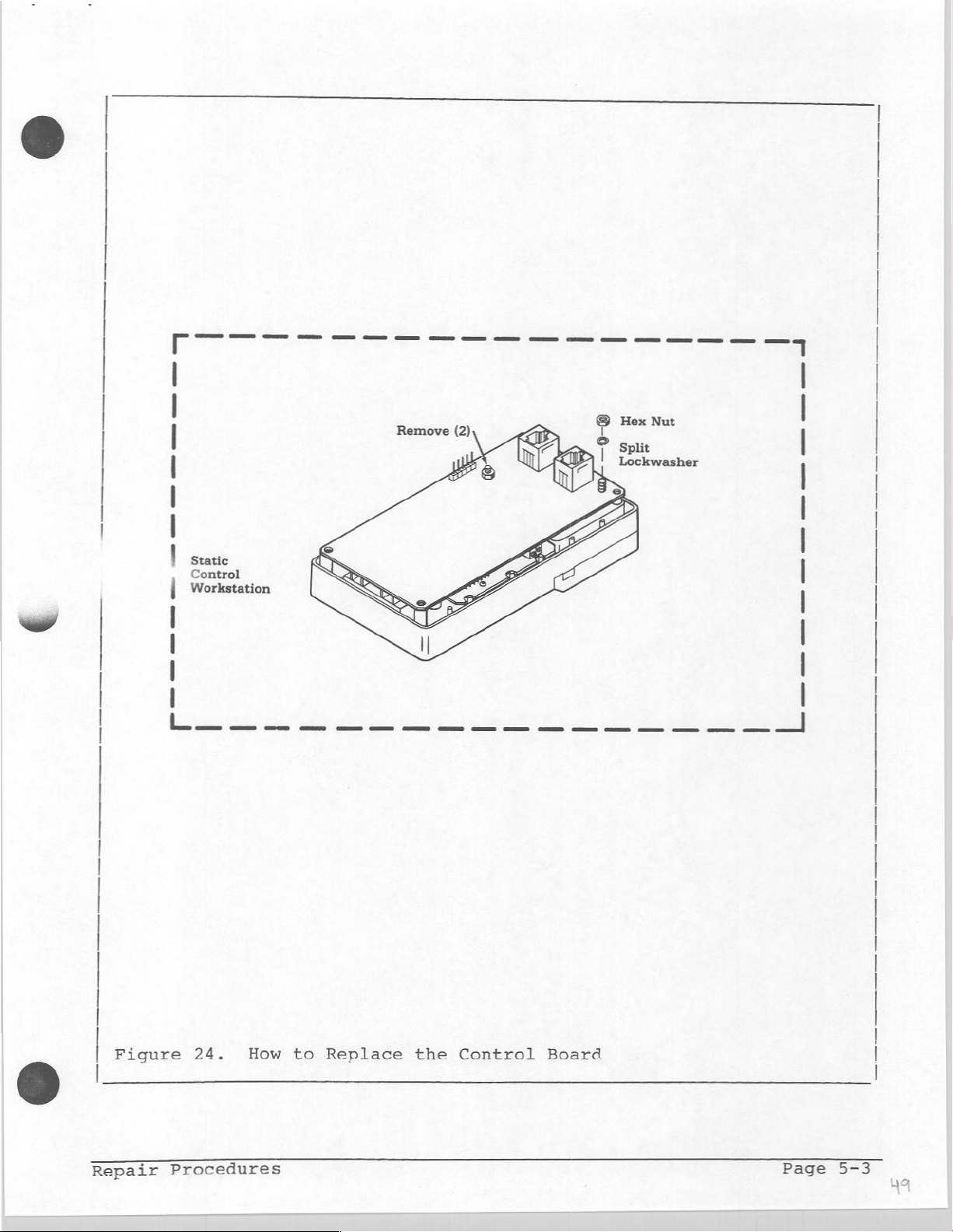
|
=
|
static
Control
|
Workstation
|
I
I
I
|
=
©
Hex
Nut
* T Split
Lockwasher
=
=
=
=
ーー
ニー
ーー
Figure
Repair
Procedures
24.
How
to
Replace
the
Control
Board
Page
5-3
na
Page 50

5.3
How
to
Replace
the
Display
Board
Refer
1.
2.
3.
4.
To
Replace
5.
6.
7.
8.
to
Figure
Remove
Remove
Remove
housing.
Lift
Ensure
front
Position
the
respective
Replace
Replace
Replace
Test
the
housing.
LCD
the
the
the
the
Display
the
that
the
display
the
the
the
monitor
25.
back
Control
four
Display
cutouts.
housing
the
lens
Display
and the
Display
Control
back
Board
screws
board
Board
board's
Board.
housing.
for
(refer
(refer
that hold
out
for
the
board
control
proper
to
of
the
LCD
into
the
switches
mounting
operation
section
to
section
the
front
display
Display
front
screws.
(refer
5.1).
5.2).
board
housing.
is
in
housing
fit
properly
to
place
making
section
to
the
in
into
front
the
sure
3.2).
@
that
their
|
|
|
|
|
o
|
Control
Workstation
|
|
|
|
|
Figure
|
| | |
25.
How
|
to
|
|
Replace
|
|
the
|
| 1 |
Display
I
Board
|
|
|
|
|
|
и
J
©
Page
5-4
Section
5.0
Page 51

5.4
How
to
replace Battery
Terminals
O
A
Refer
Le.
Open
2.
Remove
in
3.
The
Note:
terminal
replace
4.
To
a.
b.
a
d.
to
Figure
the
place
center
The
(B)
these
replace
Remove
Remove
Control
Replace
screw
battery
Replace
with
front
the
(four
screws
are
is
hex
26.
cover
back
terminals
terminals,
the
the
the
board
the
power
the
plate
screws).
which
also used
positive
back
two
to
affected terminal
tight
to
Control
nut).
and
(with
are
hold
further
housing
hex
nuts
the
in
the
the
board's
Replace
remove
now
the
to
mount
or
front
housing
Control
the
the
batteries.
label)
loose
positive
disassemblv
negative
(refer
(split
housing.
back
that
for
terminal
the
Control
end
to
section
lockwasher)
making
to
ensure
board.
mounting hardware
housing.
holds
replacement.
is
terminals,
sure
the
board,
required.
5.1).
which
that
proper
(A)
terminals
and
the
therefore,
hold
the
mounting
transfer
(split
negative
to
the
of
lockwasher
4.
5.
6.
7.
8.
Hook
Place
and
properly
Secure
in
their
Replace
Test
proper
(refer
each
the
the
the
the
monitor
operation
to
center
back
oriented
plate
front
batteries.
section
terminal
plate
making
housing
for
3.2).
over
over
the
(positive
sure
channels.
of
the
lower
terminals
terminals
the
terminals
Note
4
Orientation
Label
edge
with
down).
are
of
the
properly
the
label
front
showing
seated
housing.
Figure
Repair
26.
Procedures
How
to
Replace
the
Control
Board
Page
5-5
Page 52

Notes
Page
5-6
Section
5.0
Page 53
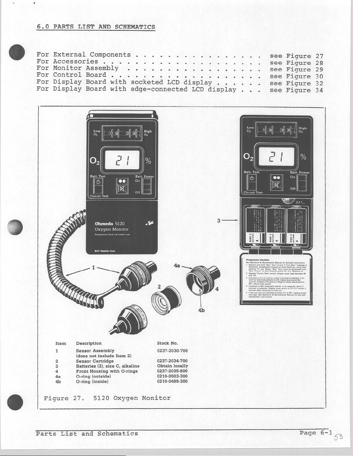
6.0
PARTS
For
External
For
Accessories
For
Monitor
For
Control
For
Display
For
Display
LIST
Components
Assembly
Board
Board
Board
AND
,
SCHEMATICS
...
.
.
. . :
with
with
socketed
edge-connected
LCD
display
LCD
dis
play
see
see
see
see
see
see
Figure
Figure
Figure
Figure
Figure
Figure
27
28
29
30
32
34
Item
pero»
Ohmeda
Description
Sensor
Assembly
(does
not
Sensor
Batteries
Front
O-ring
O-ring
include
Cartridge
(3),
Housing
(outside)
(inside)
5120
en
Monitor
Item
size
C,
with
2)
alkaline
O-rings
Stock
No.
0237-2030-700
0237-2034-700
Obtain
locally
0237-2035-800
0210-0503-300
0210-0499-300
and
5120
Schematics
Figure
Parts
27.
List
Oxygen
Monitor
Page
6-1
_.
Page 54

Item
&
Description
Sensor
Oz
Socket,
1.
Dome
2
3.
O-Ring
Seating
Nut,
4.
Nut,
5.
Chain
$.
Plug
à
O-Ring
B.
Chain
€.
d.
Ring,
e.
Coupling,
Probe
0237-2031-800
o...
Jam
Plug
&
only
split
Chain/Bead
Holder
......
:
1111111/10212-1052-200
111.
=
...
Stock
0236-0015-535
1110210-0704-300
0402-1707-535
1
0402-1531-835
No.
5
6e
22
mm
Tee
0212-0763-100
©
Manifold
©
Sensor
Cord
0237-2040-880
Cord, 6 feet
069011570819
extended
Extension
Kit
Coupler,
Modular
128-000-005
(=
Mounting
237-2032-700
1.
Knob
with
2.
Extrusion,
3.
Stud,
Clamp
4.
Disk,
Mounting..
Back
Clamp
Assembly
Stud
Assembly,
Clamp.
-1/4-20x1.431..
Duplex
0690-1950-247
Jack
Figure
Page
6-2
28.
Accessories:
Standard
and
Optional
Section
6
6.0
Page 55

@
©
©
te)
TEE
oc-ztogrzceo
rswostceo
110-0000-9109
©
w
008-9202-L820
801-199-0P10
005-SZ0Z-LEZ0
TOLZ9ew-Zrto
|
|
ot
:
À
i
e
т
|
1
1
ㅣ
I
1
1
I
|
I
£-9
0604
oF
viva
1
.0
비
시
Wied
008
10,
i
DM
ο
ο
04
©
yen
ο
полом
πι
Ktquossy
soraeueys
ronruo
pue
35FT
.6z
ezn6Td
S+20d
Page 56

"BO
a
usa
pon
she
Ἡ
veu
08
Apoq
des
oy
ojsu
“aod
wujese
ey
)・9
new
9
oa
on
om
4013295
ATquessV
4087001
sequiny
0ocwwosrreoo
1-0690
2203S
106700000000
016
196-£991-0690
(020-000-2200
0010'c090
pxeod
Toxz3uoD
・OE
exnBra
4-9
obed
9082-2308
1056
Axmosos
01086
a
‘opera
00010
ICELNA
tou
(NOM)
sqazos0@9etoi
iosseooxdorot
"DI
Page 57

5-9
0604
τ
Yo
usar
use
‘a
воз
っ
Tauauos
peog
зотзешецов
て
=
Pra
oq
Gro
hds
8628
je
を
uo
pas
ys
ca
own
2906
PT
oxuoo
pue
・rE
str
sn5a
83304
Page 58

000
Ne
x
sordos
=
des
3
ven
0:9
uof3pas,
(AeTdsTp
doT
cen
o
5025
°
ete
obe
때
060000060000000)
030!
(ОО
6
©
оо
У
2006
m
Y
10,
pou
T
(or
E
1928
E
。
“odin
・
о
x
afro
104
о
our
poncio
opme
in
uo
eipueti
ue
라드
osp
soon
之
ou
edl
Anouk
ogzro
14
03
payne
Cleu
narews
09
7001
m
GOES
6000
pu
"7020
028
Em
is
DES
"E
を
peyeyoos
103)
Atquessy
pavog
Avtdsta
,zf
sxn6Td
99
0604
100
616-0017-0690
QUIN
006-808-1600
oo
doceerrtozo
800-0000-2100
110-0000
0105
160-0000
106-2114900
1009
‘500-082-0600
210-0000-2809
‘200-000-9009
301-000-2009
289-5000
008-1210
806-0822-0890
2087:0690
2800
2009
(rozza
8
,
pietose
pra
av
renomados,
‘impedito
sorzortozo
corona
зело
oe
Toco
2020
toco
soer
τοσα
poza
1025
zozs
2028
2025
104
og
wea
corsa)
e
È
i
2v0-0000-5890
16-99-0690
300
2007
0600
eoe'zoe'voen
toe
toes
9
Page 59

В
Я
“ia
S-9020
2-02
As.
ο
DAA
ЗА
саге
9.9026
09027
temer
soar
0900
non
1-9
эбеа
soap
ANS
ISA
On
20250
ea
snivis
20
ae
av
02
HANI
1
SNOLLOANOO
SNOULI3NNOO
071»
001:
202F
1020
OR
Hana
2
cos
no
2024
NADA
ndin
№
009
1029
7
091
алан
SİNİ
2025
1025
TazzaNN
ος
13NNYHON
ΑΙΜΑ
940151684
SHa
TIY
М
ам
ENS
MN
03LON
4
au0
"SUOLIDVAVD
$S3INN
TIV
oT3eueuos
pxeot
SoTavuoyos
一
91
二
一
0000
一
一
2025
at
NI
031NNOW
SOM
dh
3100
Masi
kozu
oo
детазта
pu?
"ee
19114
eaxn5Td
93706
Page 60

гог
за
"кана
rmahxp
Pinbla
Toz
sa
leued
Ta
usos
nova
ode
0
uyuzaz
3
“sde
Bujyona
0
ooujans
zedwa
opismo
enoM
No
2009
epedg
van
9
(Кетазтр
uof3pa8
qor
penosuuoo-e5pe
cron
roj)
dl
озу
paosle
"soou
“uodeuva
“uopivistiona
чбпонц
092:
9heae
van
10
Aq
eBesors
joruoo
96wurep
107
01
aeuleauoo
190/08
peaordde
P200
9heae-huo
Auo
Ino1I9
atpus
ue
WIML
emn
"Z
*L
JO
у
03
146)
poubite
anuatxeu
eq
ant
401
025
6020
ри
"2020
‘2025
‘Busano
μι
'1025
で
人
Tduogsv
pxeog
XetdsTQ
“be
canbra
8-9
obed
Aegny
61¢-0012-0690
10621142800
1£0-0000-£009
430-000-000
29b-0981-0600
LSp-1981-0600
ee
ommbia
10015
вов
O0€-1210-9800
40020920690
808-0922-0890
250-000-890
216790070690:
900-2057-0690
210-000-2609
Eb0-0000-0009
ο
ο
nerdmoo
ο
uvoa
PIES
19015
'preog
‘uids}q
попёровеа
ov
etdard
todo
AD
・
-
20280
20090
10090
404
oewdeo
pm
olsvdeo
oetts
utety
8%
"oi
“0990S
2025
2025
1009
oa
90:
esed
60gogrozn
2025
103
Page 61

LIST
OF
ILLUSTRATIONS
Figure
Figure
Figure
Figure
Figure
Figure
Figure
Figure
Figure
Figure
Figure
Figure
Figure
Figure
Figure
Figure
Figure
Figure
Figure
Figure
Figure
Figure
Figure
Figure
Figure
Figure
Figure
Figure
Figure
Figure
Figure
Figure
Figure
Figure
Ohmeda
Standard
wi
Optional
5120
UA
Power
Microcomputer
JO
Input/Output
LCD
DO
Backlight
+
o
Front Panel
II
Sensor
125
Digital-to-Analog
Audio
13.
14.
Watchdog:
so
Alarm
16.
Remote
17.
Alarm
18.
Alarm
19.
Analog
20.
Tools
21
Test
22.
Battery
How
23.
How
24.
25.
How
26.
How
27.
5120
Accessories:
28.
29%
Monitor
Control
30.
Control
31.
Display
Display
33%
Display
34.
5120
Oxygen
Accessories
Accessories
Oxygen
Supply
Monitor,
Circuit
Si
Ports.
Display
epi
еек
Switches
Input
Alarm
Output
Alarm
Output
and
Timer’
Circuit
Converter
Alarm
«2
не
Pulse
Waveforms
Interface Circuitry
Output
and
Points
to
Remove
to
Replace
to
Replace
to
Replace
Oxygen
Test
and
Test
Monitor
Assembly
Board
Board
Board
Board
Board
Eo
Eguipment
Calibration
Verification
the
Back
the
the
the
Standard
.....
Assembly
Schematic
Assembly
Schematic
Assembly
Monitor:
. . .
.
. .
Block
.
.
<
500
. . .
. .
Indicators
eso
la
Code
.
ek
o в
Housing
Control
Display
Control
..
and
.
(for
(for
Diagram
o
do
。
.
.
ODO
on
tro
Board
Board
Board
Optional
.
・
socketed.
5
eage-connected
à
πο.
LCD
display)
LCD.
displ
ay
|
ロビ
ピロ
ee
ロロ
いら
1
1
ららら
Io
3=2
の の
の
ロロ
の
の
の の
の
の の
の
の の
나
da
UN
00
N
ль
©
NH
-
UEL
NH
UE
IO
O
Parts
List
and
Schematics
Page
6-9
/
Page 62

Ohmeda
355
Invemess
Englewood
303 799
Rapidfax
Telex
4947238
A
Division
Regional
Eastern
Fort
Lee
One
Executive
Fort
Lee
800 922
201
947
Midwestern
2101 S Arlington
Suite
145
Arlington
312 364
800 372
Pacific
5635 W Las
Suite
406
Pleasanton
800 227
800 772
Southeastern
4565
Winters
Atlanta
800
241
404
449
Drive
CO
8333
303 799
of
The
Service
Region
Executive
NJ
07024
0443
Outside
6100
In
Region
Heights
7090
5867
Region
Positas
CA
2054
Outside
3517
In
Region
Chapel
GA
30360
4300
Outside
7990
In
80112
6614
BOC
Drive
NJ
Heights
IL
94577
CA
GA
South
5810
Group
Offices
Park
NJ
Rd
60005
Blvd
CA
Rd
GA
Inc
International
Europe,
Elizabeth
Harlow
Essex
England
Telex
Latin
10700 N Kendall
Suite
Miami
Telex
Southeast
#06
5611 N Bridge
Singapore
Telex
Middle
Elizabeth
Harlow
Essex
England
Telex
Africa
Way
CM19
817566
America,
301
FL
33176
810
8486057
Asia
01
Eng
Cheong
0719
RS35276
East,
Nigeria
Way
CM19
817566
5AB
Caribbean
Dr
Road
5AB
Tower
National
Ohmeda
4507 C Mills
Atlanta
800
404
Canada
Service
172
Rexdale
416 243
Telex
Service
Place
GA
241
691
30336
6442
3635
Centre
Belfield
Road
Ontario
9533
06989362
Center
M9W
1H1
Southwestern
831
Greenview
Grand
Prairie
800
433
800 772
BOC
5070
5420
Health
Region
Drive
TX
75050
Outside
In
TX
Care
TX
Bk
Cvr
12
87
0178
04 87 B 01
Printed
©
The
BOC
Chg
0164
in
000
0102
USA
Group
Inc
 Loading...