

Ohmart Vega W-4510 Technical Reference Hardware Manual

Technical Reference
MANUAL
W-4510 WEIGH SCALE WITH GEN 2000
®
ELECTRONICS MODEL W-4510 WITH
FREQUENCY OUTPUT

W-4510 Weigh Scale
with GEN2000® Electronics
Technical Reference Manual
Model W-4510
with
frequency output
Manual part number 31559-US
Version 1.0
Preface
Revision history
Table 1: Revision history
Manual version Description Date
1.0 Initial release. Formerly 241818. 051201
Copyright © 2001-2005 Ohmart/VEGA Corporation, Cincinnati, Ohio. All rights reserved.
This document contains proprietary information of Ohmart Corporation. It shall not be reproduced in whole or in part,
in any form, without the expressed written permission of Ohmart/VEGA Corporation.
The material in this document is provided for informational purposes and is subject to change without notice.
®
is a registered trademark of The HART® Communication Foundation.
HART
GEN2000 ® is a registered trademark of the Ohmart/VEGA Corporation.
ISO 9001 approval by Lloyd’s Register Quality Assurance Limited, to the following Quality Management System
Standards: ISO 9001:1994, ANSI/ASQC Q9001-1994, Approval Certificate No. 107563.
Ohmart/VEGA Corporation
4241 Allendorf Drive
Cincinnati, Ohio 45209-1599 USA
Voice:
(513) 272-0131
FAX:
(513) 272-0133
Web site
www.ohmartvega.com
Field service email
fieldservice@ohmartvega.com
WARNING
Use this equipment only in the manner that this manual describes. If you do not use the
equipment per Ohmart/VEGA specifications, the unit is not CE compliant, and may be
damaged or cause personal injury.
ii W-4510 Weigh Scale Technical Reference Manual

Contents
Contents iii
Tables vii
Figures ix
Procedures xi
Procedures xi
Explanation of symbols xiii
Your comments xv
CHAPTER 1 : INTRODUCTION 1
Nuclear materials notice 1
Unpacking the equipment 2
Storing the equipment 3
Storing the source holder 3
Storing the detector 3
Specifications 4
Typical applications 5
Belt loading 5
Loading rate 5
Where to find help 6
Ohmart Customer Service 6
System overview 7
Principles of operation 9
Communicating with the gauge 10
Smart Pro software 10
Step-by-step method 10
Direct access method 10
Smart listing 10
Sample Smart Listing 11
Preface
CHAPTER 2 : INSTALLATION 13
Location considerations 13
Avoid source cross-talk 13
Blending applications 13
Prevent process accumulation 13
Re-cal considerations 14
Restrict air gap access 14
Weigh scale assembly 15
Source on/off lights 16
Securing the weigh scale assembly 18
Mounting the electronics console 18
Smart Pro mounting 18
Pro Pac mounting 20
Rack mount computerized electronics 21
On/Off switch with circuit breaker and pilot light 22
CPU board 22
I/O termination board 23
Case 23
Power supply 23
Hinged front panel 23
Processor select circuit board 23
Key pad assembly 23
LCD display interface circuit board 23
Operator display/interface 23
W-4510 Weigh Scale Technical Reference Manual iii

Preface
Display window 24
Data entry keys 25
Function keys 27
Access keys and indicators 28
Wiring the equipment 29
Smart Pro and Pro Pac connections 32
Power 35
Switch for CE compliance 35
Conduit 35
Auxiliary and optional equipment 36
Tachometer 36
Line down contacts 37
Commissioning the gauge 38
Can you remove the source holder lock? 38
Field service commissioning cal checklist 40
CHAPTER 3 : SETUP 41
Detailed screen description 41
Setup menus 41
Time and date 42
Time 42
Date 42
Memory functions 43
Upper Ram transfers 44
EEPROM transfers 45
Upload and download configuration program 46
Password functions 47
Analog output setup 48
Measurement span setup 54
Measurement units setup 57
Custom units 57
Comm port setup 60
Temperature compensation setup 62
Operator 63
Input channel setup 64
520 Frequency input channel #1, primary sensor signal (frequency only) 64
521 Frequency input Channel #2, tachometer/speed input 64
Output channel setup 65
Product codes 66
Channel#1 product codes 66
Channel #2 product code 66
Get linearizer data points 68
Data Collect Setup 71
Data collection interval 71
Measurement cutoff 72
Filtering 73
Type (RC exponential or rectangular window) 73
RC exponential 73
Rectangular window filtering 73
Diagnostic RC filter 73
Damping 74
Fast response cutoff 74
Selecting the filter type 75
Selecting a filter type, damping, and fast cutoff 75
Adaptive filter 76
Totalizer menu 77
Minus sign configuration 80
iv W-4510 Weigh Scale Technical Reference Manual

CHAPTER 4 : CALIBRATION 81
Process calibration 82
Calibration main menus 82
Product code screen 82
Initial calibration overview 83
Step 1: Verifying the proper measurement units 84
Step 2: Verifying the proper measurement span entries 84
Step 3: Determine the linearization 85
Step 4: Collecting data for the zero and span 86
Calibrate zero—low on process channel #1 86
Calibrate high on process—channel #1 88
Step 5: Calculating the calibration 90
Two point calibration 90
Step 6: Setting the absorber value 92
Step 7: Saving the calibration information to EEPROM 93
Periodic calibration—channel #1 functions 94
Periodic calibration overview 94
Step 1: Simple cal on low 95
Step 2: Cal Hi on absorber 96
Step 3: Simple data collect 97
Simple data collect 97
Step 4: Absorber value setup 98
Step 5: Saving the calibration information to EEPROM 98
Calibration—channel #2 functions 99
Step 1: Collecting data for the zero and span 99
Cal Lo on process 99
Calibrate zero—low on process Channel #2 100
Calibrate high on process—Channel #2 101
Step 2: Calculating the calibration 103
Step 3: Saving the calibration information to EEPROM 103
Current loop (analog output) calibration 104
Analog output 104
Calibration of the analog output signal 104
Preface
CHAPTER 5 : DIAGNOSTICS AND REPAIR 109
Communication diagnostics 109
Bi-level input 109
Hardware diagnostics 121
Jumpers 122
LED indicators 122
LED summary table 123
Maintenance and repair 124
Periodic maintenance schedule 124
Spare parts 124
Field repair procedures 125
Requesting field service 126
Requesting field service 126
Returning equipment for repair to Ohmart 126
Returning equipment for repair 127
APPENDIX I: PARAMETER BLOCKS 129
Screen 520 Frequency Input Block 129
Screen 522 Frequency Output Block 132
Screen 524 Auto Zero Log 133
Screen 525 Totalizer Block 134
Screen 527 Product Code Block 135
W-4510 Weigh Scale Technical Reference Manual v

Preface
Screen 528 Linearizer Block 137
APPENDIX II: AUTO ZERO FEATURE 139
Auto zero log 142
INDEX 143
vi W-4510 Weigh Scale Technical Reference Manual

Tables
Table 1: Revision history ii
Table 2: Explanation of symbols xiii
Table 3: Specifications list 4
Table 4: Contact information 6
Table 5: Sample Smart Listing 11
Table 6: Function key descriptions 27
Table 7: Terminal names and descriptions 30
Table 8: W-4510 interconnect to Smart Pro or Pro Pac—Measure signal 32
Table 9: W-4510 interconnect to Smart Pro or Pro Pac—tachometer signal 32
Table 10: Tachometer interconnect to Smart Pro or Pro Pac—line down signal 32
Table 11: Access levels and passwords 47
Table 12: Smart Pro CPU board jumper information 50
Table 13: Smart Pro CPU board test point information 51
Table 14: Linearizer curve chart 70
Table 15: Screen 092 minus sign configuration 80
Table 16: Calibration records 107
Table 17: Bi-level inputs, terminals, grounds, addresses, and LEDs 109
Table 18: Power supply board test points and labels 122
Table 19: CPU board test points and labels 122
Table 20: Jumper division values 122
Table 21: Power supply board LED summary table 123
Table 22: CPU board LED summary table 123
Table 23: Maintenance schedule 124
Table 24: Spare part numbers 124
Table 25: Screen 520 OR 521 Frequency input block 130
Table 26: Screen 522 Frequency Output block Channel #1 132
Table 27: Screen 522 Frequency Output block Channel #2 132
Table 28: Screen 524 Auto zero log 133
Table 29: Screen 525 Totalizer block #1 134
Table 30: Screen 525 Totalizer block #2 134
Table 31: Screen 527 Product code block 136
Table 32: Screen 528 Linearizer block 137
Table 33: Screen 529 Auto Zero feature 140
Table 34: Screen 529 Auto Zero feature 142
Preface
W-4510 Weigh Scale Technical Reference Manual vii

Preface
Notes
viii W-4510 Weigh Scale Technical Reference Manual

Figures
Figure 1: System overview 7
Figure 2: Typical source holder shutter mechanism 8
Figure 3: W-4510 assembly 15
Figure 4: Typical W-4510 detector outline 16
Figure 5: Typical W-4510 source holder outline 17
Figure 6: Typical Smart Pro dimensions 19
Figure 7: Typical Pro Pac dimensions 20
Figure 8: Rack mount interface components 21
Figure 9: Simplified CPU board 22
Figure 10: Data entry/function keys 26
Figure 11: Rack mount displays 28
Figure 12: Typical interconnect diagram 29
Figure 13: W-4510 terminal illustration 31
Figure 14: Typical interconnect diagram for Smart Pro 33
Figure 15: Typical interconnect diagram for Pro Pac 34
Figure 16: Setup screens 1–4 41
Figure 17: Time and date screen 42
Figure 18: Memory areas EEPROM vs. RAM 43
Figure 19: Memory backup screen 43
Figure 20: SmartPro upload and download application 46
Figure 21: Communication cable 46
Figure 22: Password function screens 47
Figure 23: Analog output setup screens 48
Figure 24: Smart Pro/Pro Pac CPU board jumper and test information 49
Figure 25: Simplified Smart Pro circuit board 50
Figure 26: Set gauge span screens 54
Figure 27: Measurement units setup screen 57
Figure 28: Comm port setup screen 60
Figure 29: Temp comp setup screen 62
Figure 30: Operator setup screens 63
Figure 31: Input channel setup screens 64
Figure 32: Output channel setup screen 65
Figure 33: Data collect setup screens 71
Figure 34: Totalizer menu screen 1of 3 77
Figure 35: Totalizer menu screens 2 and 3 of 3 77
Figure 36: Screen 092 main screen display 80
Preface
W-4510 Weigh Scale Technical Reference Manual ix

Preface
Figure 37: Cal menu screens 82
Figure 38: Product code screens 82
Figure 39: Graphical representation of the calibration curve 83
Figure 40: Cal Lo on process screen 86
Figure 41: Cal Hi on process screen 88
Figure 42: Two point calibration screen 90
Figure 43: Simple re-cal on low screen 95
Figure 44: Cal on absorber screen 96
Figure 45: Simple data collect screen 97
Figure 46: Absorber value setup screen 98
Figure 47:Cal Channel #2 function screen 99
Figure 48: Cal Lo on process screen 99
Figure 49: Cal Hi on process screen 101
Figure 50: Example of a bi-level input open circuit 109
Figure 51: Smart Pro power supply flow chart – part 1 110
Figure 52: Smart Pro power supply flow chart – part 2 111
Figure 53: Smart Pro TTL/Relay flow chart 112
Figure 54: Smart Pro frequency input 113
Figure 55: Smart Pro analog output (mA/mV) flow chart 114
Figure 56: Smart Pro analog input-2 flow chart 115
Figure 57: PRO PAC Frequency input 116
Figure 58: Pro Pac Analog Input-2 117
Figure 59: PRO PAC TTL/Relay flow chart 118
Figure 60: PRO PAC Analog Output (mA/mV) flow chart 119
Figure 61: PRO PAC AC voltage and power supply flow chart 120
Figure 62: CPU board simplified component layout 121
Figure 63: GEN2000 LED indicators 122
Figure 64: Frequency input Channel #1 screen 129
Figure 65: Frequency input Channel #2 screen 129
Figure 66: Frequency output channel screen 132
Figure 67: Totalizer screen 134
Figure 68: Product code table screen 135
Figure 69: Linearizer curve screen 137
Figure 70: Auto zero screen 140
Figure 71: History index screen 142
x W-4510 Weigh Scale Technical Reference Manual

Procedures
Procedure 1: Change time and date 42
Procedure 2: Transfer to upper RAM 44
Procedure 3: Transfer to RAM 44
Procedure 4: Upload to EEPROM 45
Procedure 5: Input password 47
Procedure 6: Change password 47
Procedure 7: Select output type 51
Procedure 8: Setup analog output Channel #1 52
Procedure 9: Setup analog output Channel #2 53
Procedure 10:Setup gauge span—Channel #1 55
Procedure 11:Setup gauge span—Channel #2 56
Procedure 12: Setup units of measurement for Channel #1 and #2 58
Procedure 13: Setup communication port 61
Procedure 14: Setup operator screen 63
Procedure 15: Setup product code 67
Procedure 16: Take datapoints for linearizer curve 69
Procedure 17: Selecting a filter type, damping, and fast cutoff 75
Procedure 18: Setting up an adaptive filter 76
Procedure 19: Setup totalizer #1 78
Procedure 20: Setup totalizer #2 78
Procedure 21: Setup totalizer #1&2 total units 79
Procedure 22: Verify units of measurement 84
Procedure 23: Verify proper measurement span entries 84
Procedure 24: Verify the curve is loaded into Smart Pro 85
Procedure 25: Collect data for zero Channel #1—low on process 87
Procedure 26: Collect data for span Channel #1—high process 89
Procedure 27: Calculate calibration—Channel #1 91
Procedure 28: Set absorber value 92
Procedure 29: Save calibration information to EEPROM 93
Procedure 30: Simple re-cal Channel #1 95
Procedure 31: Cal Hi on absorber—Channel #1 96
Procedure 32: Simple data collect—Channel #1 97
Procedure 33: Absorber value setup—Channel #1 98
Procedure 34: Collect data for zero Channel#2—low on process 100
Procedure 35: Collect data for span Channel#2—high process 102
Procedure 36: Calculate calibration—Channel #2 103
Preface
W-4510 Weigh Scale Technical Reference Manual xi

Preface
Procedure 37: Calibrate the analog output signal—Channel#1 105
Procedure 38: Calibrate the analog output signal—Channel#2 106
Procedure 39: Returning equipment for repair 127
Procedure 40: Auto Zero feature 141
xii W-4510 Weigh Scale Technical Reference Manual
Explanation of symbols
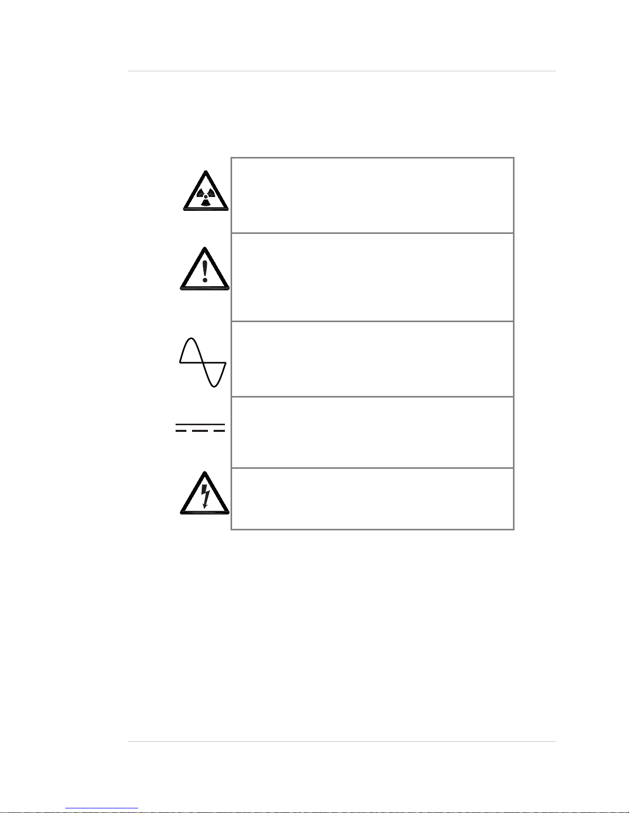
Table 2 lists the symbols that the manual and instrument use.
Table 2: Explanation of symbols
Preface
Radiation notice
In the manual, information concerning radioactive materials
or radiation safety information is found in the accompanying
text.
Caution! The text next to this symbol contains the warning
of potential damage to equipment or people.
Attention! Le texte apparaissant près de ce symbole vous
informe d’un danger possible pour l’équipement ou pour
l’usager.
AC current or voltage
On the instrument, a terminal to which or from which an
alternating (sine wave) current or voltage may be applied or
supplied.
DC current or voltage
On the instrument, a terminal to which or from which a
direct current voltage may be applied or supplied.
Potentially hazardous voltages
On the instrument, a terminal on which potentially
hazardous voltage exists.
W-4510 Weigh Scale Technical Reference Manual xiii

Preface
Notes
xiv W-4510 Weigh Scale Technical Reference Manual

Preface
Your comments
Ohmart values your opinion! Please fill out this page so that we can continually improve our
technical documentation.
Manual: W-4510 Weigh Scale with GEN2000 Electronics Technical Reference Manual
Date: ______________
Customer Order Number: ___________________
How we can contact you (optional if you prefer to remain anonymous):
Name: _________________________
Title: _________________________
Company: __________________________
Address: __________________________
__________________________
__________________________
Did you find errors in this manual? If so, specify the error and page number.
Did you find this manual understandable, usable, and well organized? Please make
suggestions for improvement.
Was information you needed or would find helpful not in this manual? Please specify.
Please send this page to:
Ohmart Corporation
Director of Engineering
4241 Allendorf Drive
Cincinnati, OH 45209-1599
W-4510 Weigh Scale Technical Reference Manual xv

Preface
Notes
xvi W-4510 Weigh Scale Technical Reference Manual
Chapter 1: Introduction
Nuclear materials notice
This equipment contains radioactive source material that emits gamma radiation. Gamma
radiation is a form of high-energy electromagnetic radiation. Only persons with a specific
license from the U.S. NRC (or other regulating body) may perform the following to the source
holder:
• Dismantle
• Install
• Maintain
• Relocate
• Repair
• Test
Ohmart Field Service engineers have the specific license to install and commission nuclear
gauges, and can instruct you in the safe operation of your density gauge. To contact Ohmart
Field Service, call 513-272-0131. Users outside the U.S. and Canada may contact their local
representative for parts and service.
Note: Special instructions concerning your source holder are found in
the envelope that was shipped with the source holder and the
“Radiation Safety for U.S. General and Specific Licensees, Canadian
and International Users” and the “Radiation Safety Manual Reference
Addendum” CD. Please refer to this document for radiation safety
information.
W-4510 Weigh Scale Technical Reference Manual 1
Introduction
Unpacking the equipment
CAUTION!
Make sure that you are familiar with radiation safety practices in
accordance with your U.S. Agreement State, U.S. NRC, or your
country’s applicable regulations before unpacking the equipment.
5 Unpack the unit in a clean, dry area
5 Inspect the shipment for completeness, by checking against the packing slip
5 Inspect the shipment for damage during shipment or storage
5 If the detector is included as a separate package in the shipment, inspect the assembly for
damage that may have occurred during shipment or storage
5 If there was damage to the unit during shipment, file a claim against the carrier and report
the damage in detail. Any claim on the Ohmart Corporation for shortages, errors in
shipment, etc., must be made within 30 days of receipt of the shipment
5 If you need to return the equipment, see the section “Returning equipment for repair to
Ohmart” in the “Diagnostics and Repair” chapter
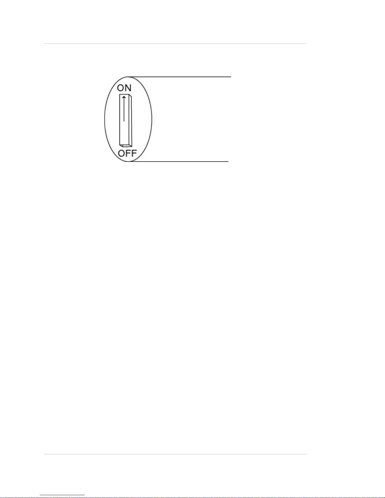
5 After you unpack the equipment, inspect each source holder in the shipment to assure that
the operating handle is in the OFF position. In the event that you find the handle in the ON
position, place it in the OFF position immediately and secure it.
Note: Most source holder models accept a lock. Call Ohmart Field Service
immediately for further instructions, at 513-272-0131, if the source holder
has one of the following conditions:
• Does accept a lock and there is no lock on it
• The lock is not secured
• You are unable to secure the lock
• The operating handle does not properly move into the off position
2 W-4510 Weigh Scale Technical Reference Manual

Introduction
Storing the equipment
Storing the source holder
If you must store the source holder, adhere to the following guidelines:
• Store in a clean, dry area.
• Verify that the source holder shutter is in the OFF or CLOSED position.
• Check the current local regulations (U.S. NRC, Agreement State, or other) to determine if
this area must have any restrictions.
Storing the detector
If you must store the detector, adhere to the following guidelines:
• Avoid storage at temperatures below freezing.
• Store the detector indoors in an area that has temperature-control between 50 ºF and 95
ºF (10 ºC and 35 ºC) and less than 50% relative humidity.
• Store equipment in dry conditions until installation.
W-4510 Weigh Scale Technical Reference Manual 3

Introduction
Specifications
Table 3: Specifications list
System
Accuracy
Typical
Sources
Requirements*
Signal Cable Maximum length 5,000 feet (1,500 meters)
Source
Housing
W-4510
Detector
Housing
Input Signal input channels Two digital (frequency) 0–32kHz opto-isolated
Analog inputs Voltage or current, 0–0.1VDC into 1megaohm, 0–1.0VDC into 1megaohm,
TTL Logic level input
Output Relay 4 SPDT (4 form C) contacts: 2A–120VAC, 2A–28VDC, 1A 250VAC, CSA
TTL logic level Five open-collector transistor type capable of sinking 300mA (max) and
Analog channels Two 0–20mA into 0-1,000ohms, or 4–20mA into 0–1,000ohms, 0–
Serial ports Serial ports for local display and keypad, remote displays, and host
Signal Processing
Electronics On-board memory EEPROM and battery-backed RAM
Real-time clock Maintains time, date, and source decay compensation. Y2K compliant
Diagnostics LED indication +5V, Memory Corruption, CPU Active, Auxiliary, and High Voltage
±1% of span typical Accuracy depends on specific application parameters
Cesium-137 0.66MeV gamma radiation emitter, 30.2 year half life
AC 115VAC ±10% 50 or 60Hz, at 65 Watts maximum power consumption Power
Wiring #14–#22AWG (1.63–0.643mm)
Indicator On/Off light indicator
Calibration absorber Self-contained calibration absorber
Material Steel construction
Weight 450lbs
Paint Epoxy Powder Coat
Enclosure rating NEMA 4X
Ambient temperature –40°F to 140°F (–40°C to 60°C)
Humidity 0–95%, non-condensing
Material Aluminum
Weight ≅100lbs
Paint Epoxy Powder Coat
0–10VDC into 1megaohm, 0–1.0mA into 10kohm, 1–5mA into 2kohm,
4–20mA into 500ohm, 10–50mA into 200ohm
channels
capabilities
Six TTL input channels, voltage-free contacts from relay or switch, contact
loading 5V at 5milliamperes, maintain contact for one second (minimum)
version ratings: 0.6A–125VAC, 0.6A–110VDC, 2.0A at 30VDC
30V (max) resistive load, or 20V (max) inductive load and one
configurable to be isolated. If using a TTL for a totalizer, the max rate is 10
pulses per second.
100mVDC into 20kohms (min). Both sides of output are isolated from input
and ground. Ground either side. Meets ISA Standard 50.1: Type 4, Class
U isolated current loop transmitters.
interface. Two full and two partial RS-232C ports, or one partial RS-232C
port and one partial RS-422/485 port, and individual settings from 300
baud–19,200 baud.
Capabilities include: Linearization, display process measurement in
product units, generate high and low process alarms, filtering digital or
classic RC time constant, source decay compensation, and temperature
compensation.
4 W-4510 Weigh Scale Technical Reference Manual

Introduction
Typical applications
Belt loading
The W-4510 Weigh Scale can measure the belt loading (weight per linear distance) of
product on the belt. This signal can combine in the DCS/PLC with the belt speed to calculate
the mass flow (weight per unit time). This is essential for blending operations, as in OSB or
MDF/particleboard application to match the amount of resin to the weight of wood present.
Loading rate
The W-4510 Weigh Scale can measure the loading rate of product on the belt. This uses a
tachometer directly connected to the W-4510 to measure the belt speed. The output signal
data calibrates directly to the mass flow units (weight per unit time).
W-4510 Weigh Scale Technical Reference Manual 5

Introduction
Where to find help
If you need help finding information, check the Index and Table of Contents within this
manual. Also, refer to the Smart Pro Reference manual for information on calibration and
operation with the Smart Pro.
Ohmart Customer Service
Ohmart Customer Service has Field Service Engineers located across the U.S. for on-site
service to the U.S. and Canada. In many cases, a Field Service Engineer is at your plant for
the start up of your gauge. In addition, Field Service Engineers regularly assist customers
over the phone.
If you have a question or need help, call Customer Service during office hours. If your
problem is an emergency (for example, line shut down because of Ohmart equipment), you
can reach us 24-hours a day.
Table 4: Contact information
Ohmart Phone 513-272-0131
Ohmart FAX 513-272-0133
Ohmart Field Service E-mail fieldservice@ohmartvega.com
In addition, Ohmart provides field service for customers outside the U.S. and Canada.
Customers outside the U.S. and Canada can contact their local Ohmart representative for
parts and service.
When calling with a question, if possible, please have the following information ready:
5 Ohmart Customer Order (C.O.) Number—Locate on the engraved label on the source
holder
5 Sensor serial number—Locate on the sensor housing inside the external housing
6 W-4510 Weigh Scale Technical Reference Manual
Introduction
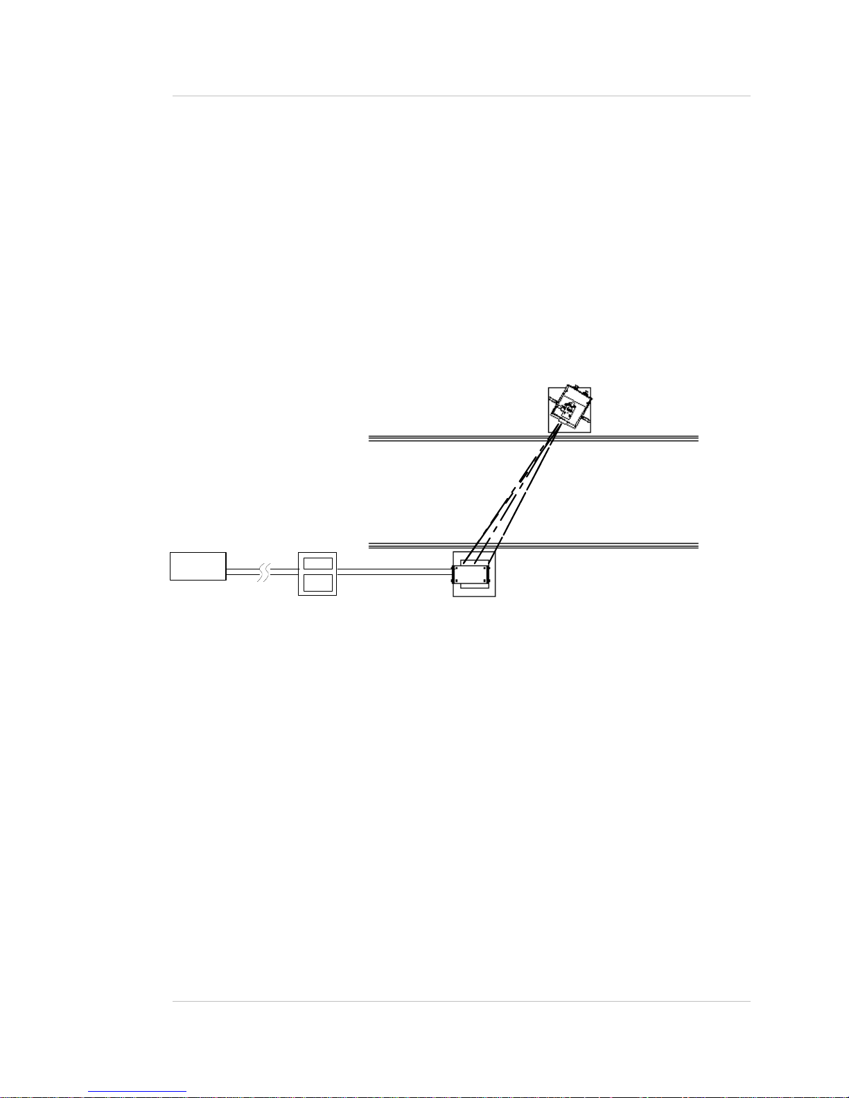
System overview
The W-4510 Weigh Scale detector uses Ohmart’s GEN2000 electronics. The W-4510 Weigh
Scale system consists of three main components:
• Source holder
• W-4510 Weigh Scale detector assembly (includes GEN2000 sensor and GEN2000 power
supply and communications)
• Smart Pro or Smart Pro Pac electronics
Source
Conveyor
4-20 mA
current loop
DCS
Smart
Pro
Frequency
output
Detector
Figure 1: System overview
The following statements describe the source holder:
• A cast or welded steel and lead enclosure that houses a radiation-emitting source
capsule
• Directs the radiation in a narrow collimated beam through the process material
• Shields the radiation elsewhere
• A shutter on the source holder either completely shields the radiation (source off) or
allows it to pass through the process (source on)
• Self-contained calibration absorber for performing a Two-point calibration on an empty
belt.
W-4510 Weigh Scale Technical Reference Manual 7
Introduction
Figure 2: Typical source holder shutter mechanism
The following statements describe the functions of the W-4510 Weigh Scale detector
assembly:
• Mounts opposite the source holder
• Inside the housing is a scintillation material
• The scintillation material produces light in proportion to the intensity of its exposure to
radiation
• A photomultiplier tube detects the scintillator’s light and converts it into voltage pulses
• The microprocessor receives these voltage pulses after amplification and conditioning by
the photomultiplier tube
• The microprocessor and associated electronics convert the pulses into a calibratable
output to the Smart Pro electronics
• The Smart Pro electronics receives and reads the input and converts it into process units
• Several outputs are available on the Smart Pro, including a 4–20mA output of the
process variable. Refer to the Smart Pro Reference manual for more information.
8 W-4510 Weigh Scale Technical Reference Manual

Introduction
Principles of operation
Ohmart’s W-4510 Weigh Scale is a nuclear gauge that mounts outside the conveyor
footprint. The detector receives a narrow beam of radiation, through the process material,
from the source holder.
The amount of radiation that the detector senses is in proportion to the amount of the
material’s mass. Since the radiation source and detector are always the same distance apart,
the only possible change in signal is directly a measure of the loading belt. A belt with a light
load allows more radiation to pass through to the detector. A belt with a heavier load allows
less radiation to pass through to the detector.
The Smart Pro calibrates the W-4510 Weigh Scale output and associates the digitized
detector readings, known as counts (the detector frequency output), with the loading of the
belt, in engineering units. The output range of the Smart Pro with the W-4510 Weigh Scale
are two
4–20mA current loop signals, in proportion to either the loading (pounds per linear foot), or
weight transfer rate (pounds per hour). In addition to the analog outputs, there are up to four
process relays available to convey totalization or other configurable alarm conditions.
W-4510 Weigh Scale Technical Reference Manual 9

Introduction
Communicating with the gauge
Use either a Smart Pro or Smart Pro Pac to enable the following:
• Initial setup
• Calibration
• Operation
Smart Pro software
The Smart Pro software is accessible through the Smart Pro wall mount or rack mount units.
You can use step-by-step method of screen selection for pre-programmed routines or direct
access to screens.
Step-by-step method
The step-by-step method takes you from the Main menus to the sub-menus by moving the
cursor to your choice and pressing SELECT and ENTER. You can press the NEXT SCREEN
and PREVIOUS SCREEN to take you back and forth between menus.
Direct access method
Use direct access to bypass the step-by-step progression of screens and go directly to your
chosen screen. You enter the screen number in the number field in the left hand corner and
press ENTER. For more information concerning function and data entry keys, refer to page
27.
Smart listing
The Smart Listing is a table of RAM addresses that lists the data that is stored at each
address.
This listing contains the software settings that configure each system for individual and
unique applications. You do not normally need this list, since all necessary information for
normal operation is accessible through user-friendly screens.
The top line of the listing’s label is Filename. It displays the following information:
• Shop order name
• Shop order number
• Date of printout
• Time of printout
10 W-4510 Weigh Scale Technical Reference Manual

Introduction
The first column down the left side is the base number. The base number represents the
address. The first row across the top is the displacement
from the base (incremental value).
Each address location is itemized by adding the displacement to the base.
Address location = base + displacement
For example, find 40 going down the first column and follow it across to the 12 located in the
top row. This represents address location 52 (40+12) and contains data 17196.
The LOW process value used to calibrate the gauge at the factory is at address location 153
(140+13). In this sample, that data value is 8427.
Sample Smart Listing
Table 5: Sample Smart Listing
Filename: A.B.C., Inc. (BJCX-0020-12133) 1-10-2001 16:17:18 Page 1
ADDR 0 1 2 3 4 5 6 7 8 9 10 11 12 13…
0 8191 16668 . 10 11 . 1668 . . . . . . 65153
20 534 37121 . . . 5500 1644 110 1991 . . . . 21760
40 16896 . 16946 . 16996 . 17046 . 17096 . 17146 . 17196 .
60 . . . . . . . . . . . . . .
80 . . . . . . . . . . . . . .
100 . . . . . . . . . . . . . .
120 . . . . . . . 1000 1 . . . . .
140 11103 11103 1807 . . . . . . 500 . . . 8427
160 . 6500 7657 7410 1 60 110 8427 5920 . . . 109 9000
…
…
…
Note: This example shows only a partial listing. The actual listing has 20 displacement fields.
In addition, a dot (.) represents the zeros (0) in this example, to enhance readability.
W-4510 Weigh Scale Technical Reference Manual 11

Introduction
Notes
12 W-4510 Weigh Scale Technical Reference Manual
Chapter 2: Installation
Location considerations
When you ordered the W-4510 Weigh Scale, the source was sized for optimal performance.
Notify Ohmart prior to installation of the gauge if the location of the gauge is different from the
original order location. Proper location of the density gauge can sometimes mean the
difference between satisfactory and unsatisfactory operation.
Note: Try to locate the source holder in such a place that process
material will not coat it. This ensures the continuing proper operation
of the source ON/OFF mechanism. Many regulatory agencies (for
example, the U.S. NRC) require periodic testing of the ON/OFF
mechanism. Refer to the “Radiation Safety for U.S. General and
Specific Licensees, Canadian and International Users” and the
“Radiation Safety Manual Reference Addendum” CD that came with
the source holder and the appropriate current regulations for details.
Avoid source cross-talk
When multiple adjacent conveyors have nuclear gauges, you must consider the orientation of
the source beams so that each detector senses radiation only from its appropriate source.
The best orientation, in this case, is for the source holders to be on the inside with radiation
beams pointing away from each other.
Blending applications
Place the scale on a flat or trough conveyor. The scale can also accommodate any conveyor
inclination angle. However, you must determine the exact location of the scale when ordering
the scale and adhere to the original location as ordered. A changing profile causes unwanted
measurement error. Some rotary feed systems tend to cause loading variations with time.
Prevent process accumulation
Prevent process material or dirt from accumulating between the source and the detector.
Such accumulation can cause the gauge to indicate a higher weight than actual.
W-4510 Weigh Scale Technical Reference Manual 13
 Loading...