

OHM BRS-12A3 User Manual
Manchester - England
12” active 3 channel subwoofer
BRS-12A3
User Manual

BRS-12A3 User Manual SCD/ATT Version 1.2 29-04-2019
2
Wellington Close
Parkgate Industrial Estate
Knutsford
Cheshire
WA16 8XL
United Kingdom
Tel: +44 (0)1565 654641
Email: info@ohm.co.uk
Website: www.ohm.co.uk
aural ltd

BRS-12A3 User Manual SCD/ATT Version 1.2 29-04-2019
3
Introduction .................................................................................................................................
Welcome to the Ohm family ............................................................................................
Unpacking ..........................................................................................................................
Register your product ......................................................................................................
Safety precautions ......................................................................................................................
BRS-12A3 Subwoofer .................................................................................................................
Description .........................................................................................................................
Key Features ......................................................................................................................
Rear Panel Overview .........................................................................................................
System Wiring .............................................................................................................................
Mains Wiring .....................................................................................................................
Speakon Wiring .................................................................................................................
XLR Wiring ........................................................................................................................
Additional Deployment and operating precautions ................................................................
LCD Touchscreen ......................................................................................................................
LCD control Menu Overview ..........................................................................................
Adjustment ........................................................................................................................
Screen Off .........................................................................................................................
LCD Touchscreen Menu Tree ........................................................................................
Initial System Testing ..................................................................................................................
Pro-A-Sync ...................................................................................................................................
Download Software ..........................................................................................................
Start-up Window ................................................................................................................
Menu and Firmware Updates .......................................................................................
Controller Window ............................................................................................................
Header Menu .....................................................................................................................
Main Tab ...........................................................................................................................
Input Tabs (PEQ) ...............................................................................................................
Output Tabs (PEQ) .............................................................................................................
Technical Specifi cation ..............................................................................................................
Dimensions and Accessories ...................................................................................................
2D Drawing and Dimensions ...........................................................................................
3D Drawing .......................................................................................................................
Accessories and Spare Parts ........................................................................................
BRSC-12 Cradle Fitting Instructions ......................................................................................
Example System Set-ups .......................................................................................................
OHM (Aural LTD) Product Warranty .........................................................................................
Troubleshooting Guide ..............................................................................................................
4
4
4
4
5
6
6
6
6
7
7
7
8
9
9
9
10
10
11
12
13
13
13
13
14
14
16
17
18
20
21
21
21
21
22
23
24
25
Contents

BRS-12A3 User Manual SCD/ATT Version 1.2 29-04-2019
4
We have spent the last 40 years perfecting building practices, honing the acoustic envelope whilst constantly
redefi ning what is possible in pursuit of the perfect product.
Thank you for your faith in our products and purchasing this equipment that we are proud to manufacture.
Everything we make is built with care and consideration, delivering many years of sonic excellence with industry
leading reliability.
We hope you enjoy using your new equipment.
Upon delivery, please check the carton and BRS-12A3 for damage which could have occurred in transit. If any is
found, please contact the delivery courier to start a claim. Keeping the packaging is a great way of making sure
that any future vacations the unit needs to make are as secure as possible.
This BRS-12A3 has been made with our environment in mind. There are many items used in its manufacture
which are highly recyclable when the unit has reached the end of its useful life. Please contact your local authority
to arrange responsible disposal.
Unpacking
Register your product
Welcome to the Ohm family.
Remember to register your product to take advantage of our free 1 year extension. Simply
follow the QR code to take you to our online registration portal or visit
www.ohm.co.uk/
registration
from any computer.
Alternately fi ll in the warranty form included with your product and return to us within 90
days of purchase.
We acknowledge all warranty applications by email. It’s important to keep this notifi cation
for future reference
Introduction

BRS-12A3 User Manual SCD/ATT Version 1.2 29-04-2019
5
Safety Precautions
Read these instructions carefully to help avoid personal injury and equipment damage.
Professional loudspeaker systems can create sound pressure levels that can be dangerous to health.
Even moderate sound levels (90 dB SPL or more) can cause permanent damage to hearing if you are exposed
to it over a long period.
To help prevent injury, please refer to the following information:
• Be sure to leave enough distance between speakers and the public
• Ensure that all hardware, fi xings and fasteners used for installation, mobile, hung or ground-stacked use are
of an appropriate size and load safety factor. Pay attention to all instructions and relevant safety guidance
on datasheets
• Regularly check the loudspeaker cabinets, accessories and load bearing bolts for visible signs of wear &
tear. Replace when necessary
• Read, retain and fully understand the user manual before use
• Do not install near heat sources e.g. radiators, heat registers or fi res and avoid direct sunlight
• Keep away from moisture, humidity or rain. Liquid should not be stored/placed on top of the unit
• Keep all ventilation surfaces clean and un-obstructed
• This CLASS 1 product always requires an earth connection when connected to mains power
• Before powering up the system, make sure all connections have been properly made
• Ensure all wiring is safe to use and complies to your local standards
• Unplug the unit when not in use, during electrical storms or mains voltage disturbance
• To prevent shock risk, never open this product; there are no parts inside that are serviceable by the user
• Do not attempt to modify or change the unit’s operational specifi cations
• For service, please return the module to Ohm for appropriate care
• This product requires a mains connection to work
• If the unit works in an unintended way, disconnect from the power and contact Ohm for support
• Do not suspend the unit from its handles
• Ohm strongly recommends this product is only installed/operated by qualifi ed professionals
• This BRS-12A3 is not designed for permanent outdoor use
Potential risk of equipment damage.
Speakers have a permanent magnetic fi eld. Magnetic fi elds can cause damage to magnetic data media, Hard
disk drives and other equipment. Keep all loudspeakers at least 1m away from sensitive equipment.

BRS-12A3 User Manual SCD/ATT Version 1.2 29-04-2019
6
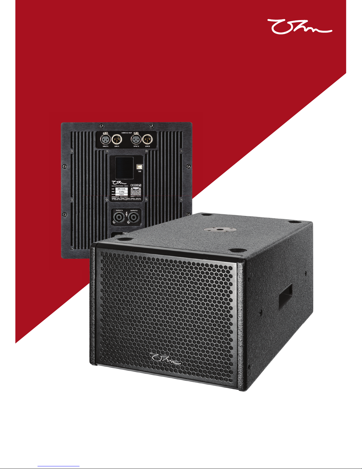
BRS-12A3 is a compact, active, 3 channel subwoofer system with 1 x 12” long excursion driver. Integrated Class D
amplifi ers deliver 2 kW’s of output through 3 DSP channels which can be adjusted locally or remotely confi gured
through a Windows PC or Mac computer which has Pro A Sync software installed.
A low-profi le design height of 333 mm allows for installation in confi ned spaces, under seating or ceiling mounted
(using optional hardware).
Designed with integrated handles and pole mounting plate for portable applications.
Key Features:
• 3 Channel amplifi ed system with parallel subwoofer output
• Rebated Baltic Birch Plywood construction
• Universal 100 to 240 Volt mains operation (AC only)
• Integrated Class D Power modules
• Passive cooling provides silent operation and low maintenance
• Fully integrated peak and RMS limiters with active Gain Reduction
• LCD touchscreen selection and adjustment to gain, preset, phase and channel mutes
• 2 kW Amplifi cation, 1 kW for internal bass driver & parallel Sub, 2 x 500 W for satellite loudspeakers
BRS-12A3 Subwoofer
USB (Type B)
Cooling
Fins
Output B
Channel 3 4Ω Minimum Load
Channel 1 (sub link for BRS-12-2
only)
Input A
Link A
Audio input & signal link outputs
Input B
Link B
Power link
output
NAC3MX-W
LCD
Touchscreen
Output A
Channel 2
4Ω Minimum Load
Power Input
NAC3FX-W
Rear Panel Overview
BRS-12A3
25.6 kg
000012
Description:
BRS-12A3 User Manual SCD/ATT Version 1.2 29-04-2019
7
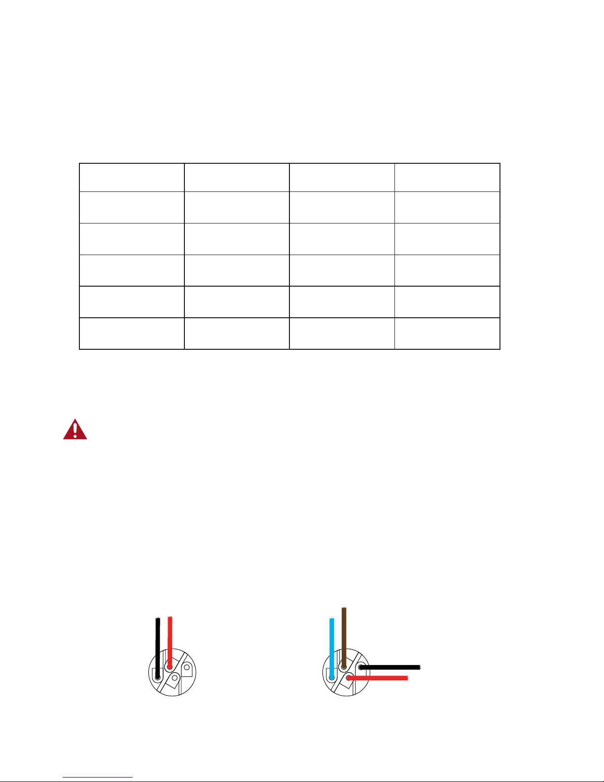
Mains Wiring
System Wiring
The mains input and power link output are via Neutrik powerCON True1 connectors. The input connector
(NAC3FX-W) is supplied with the unit. The output link is type NAC3MX-W and available separately.
Only fl exible copper wire should be used. We recommend a minimum diameter of 1.5mm per conductor but
recommend 2.5mm. Colour coding for wiring alters from one region to another. Please check and confi rm your
local colour code.
Insert the phase conductor into the receptacle marked (L) and tighten the screw terminal with a T8 Torx bit.
Repeat the process with the non-phase conductor into the (N) connection and the earth wire into the (earth
symbol) connector on the trueCON plug. Refi t the cable clamp and tighten the collar onto the plug chassis.
Region Phase (Live) Non-phase (Neutral) Earth
Europe, South Africa Brown Blue Green/Yellow striped
Australia, New Zealand Brown or Red Blue or Black Green/Yellow striped
Brazil Yellow or Red Blue Green
USA, Canada Black White Green/Yellow striped
Asia Red / Yellow / Blue Black Green/Yellow striped
All mains wiring should only be carried out by a competent, qualifi ed electrician.
Speakon Wiring
Two 4-way speakON® connectors are used for connections to satellite mid-high speakers & subwoofer. Mating
connector type is NL4FC.
Wiring is as follows:
Channel B Output
1+ Phase output
1- Non-phase output
2+ Subwoofer phase output
2- Subwoofer non-phase output
Channel A Output
1+ Phase output
1- Non-phase output
Non-phase
Mid-high
phase
Positive
Mid-high
Non-phase
Subwoofer non-phase
Subwoofer phase
1+
1-
2+
2-
1+
1-
2+
2-

BRS-12A3 User Manual SCD/ATT Version 1.2 29-04-2019
8
12
3
21
3
Male
XLR
Female
XLR
+
+
Balanced XLR
Unbalanced XLR
12
3
21
3
Male
XLR
Female
XLR
+
+
XLR Wiring
XLR Input sockets are provided to connect a signal source. Output links offer the ability to daisy-chain low level
input signal to another BRS-12A3 system.
Wiring is industry standard with the following assignments:
Pin 1 Chassis/Ground
Pin 2 Phase/positive (hot) signal
Pin 3 Non-phase/negative (cold) signal
When using the system with an unbalanced input, link pins 1 & 3 together.
Do not overload the internal amplifi ers by using unsuitable loads/impedances. The mid-high outputs are designed
to give maximum output at 4Ω. Ensure all cabling is in good condition with suitable connectors terminated
appropriately. Failing to consider output impedances or using poor quality/damaged cables will signifi cantly
impact sound quality and system reliability.
 Loading...