

Page 1
V
Cannondale P/N 951-6001126
Page 2
Safety signals
Important information concerning safety is
distinguished in this manual by the
following notations:
The Safety alert symbol means:
Caution! Your safety is involved.
WARNING!
Failure to follow warning instructions
could result in severe or fatal injury
to anyone working with, inspecting or
using the suspension, or to bystanders.
CAUTION!
Caution indicates that special precautions must be taken to avoid damage to the suspension.
NOTE!
This indicates information that is of
importance with regard to procedures.
© Öhlins Racing AB.
All rights reserved.
Any reprinting or unauthorized use
without the written permission of
Öhlins Racing AB is prohibited.
Printed in Sweden.
Introduction
All of Öhlins advanced suspension products are
adepted to the brand and model. This means that
length, travel springaction and damping characteristics, are tested individually just for the vehicle that you have decided to fit with Öhlins suspension.
Before installation
Öhlins Racing AB can not be held responsible for
any damage whatsoever to shock absorber or
vehicle, or injury to persons, if the instructions for
fitting and maintenance are not followed exactly.
Similarly, the warranty will become null and void
if the instructions are not adhered to.
Contents
Saftey signals ................................................ 2
Tuning the suspension ................................... 3
Design ........................................................... 3
Function ........................................................ 4
Compression damping ................................ 4
Rebound damping ....................................... 4
Settings ......................................................... 5
Preload adjustment ....................................... 6
Setting the damping ...................................... 7
Setting your vehicle: ...................................... 7
Start with rebound damping ........................ 8
Compression damping ................................ 8
Inspection and maintenance ......................... 9
WARNING!
1. Installing a shock absorber, that is not
approved by the vehicle manufacturer, may
affect the stability of your vehicle. Öhlins
Racing AB cannot be held responsible for
any personal injury or damage whatsoever
that may occur after fitting the shock
absorber. Contact an Öhlins dealer or other
qualified person for advice.
2. Please study and make certain that you
fully understand all the mounting instructions
and the owners manuals before handling this
shock absorber kit. If you have any questions
regarding proper installation procedures,
contact an Öhlins dealer or other qualified
person.
3. The vehicle service manual must be
referred to when installing the Öhlins shock
absorber
NOTE!
Öhlins products are subject to continual improvement and development. Consequently, although
these instructions include the most up-to-date
information available at the time of printing, there
may be minor differences between your suspension and this manual. Please consult your Öhlins
dealer if you have any questions with regard to
the contents of the manual.
2
Page 3
Oil
Oil
Gas
Oil
Shock absorber position
Gas and
oil
Gas
Shock absorber
piston
Separating
piston
Tuning the suspension
Road holding qualities
All vehicles are designed with a suspension geometry that includes wheel movements and angles. The changing of components can affect this
and it is therefore essential that both the rear and
the front ends match each other.
Changing to Öhlins suspension gives optimum
performance only when both the front and the
rear suspension interact properly. It is of greatest
importance that the front and rear loaded height
(ride height sag) are within the specified values
in the Mounting instructions.
4312
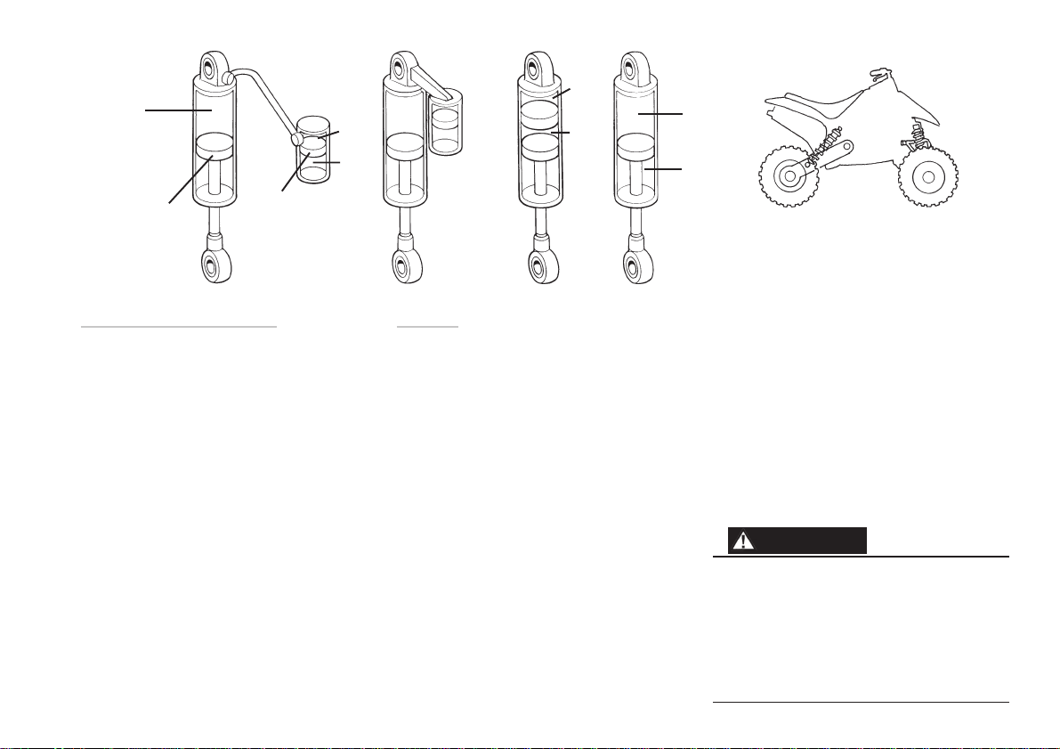
Design
Most of Öhlins suspensions are of the De Carbon
type. The fluid is put under gas pressure and the
gas and the fluid are kept apart by a separating
piston. The separating piston is often fitted in a
separate fluid reservoir, connected by hose (Fig.1)
or fixed direct on top of the shock absorber (Fig.2)
(piggyback).
There are also models where the separating
piston is fitted inside the main shock absorber (Fig.3)
(internal gas reservoir). Öhlins even manufacture a
small number of emulsion shock absorbers that do
not have a separating piston (Fig.4).
Pressurization of the fluid is made with nitrogen.
The pressurization prevents cavitation of the fluid
and the shock absorbing action is therefore more
even. The external fluid reservoirs also contribute
to better cooling of the fluid, giving longer service
life to both the fluid and components.
Öhlins shock absorbers have integrated
temperature compensation. As the temperature
increases and the fluid flows more easily the flow
Oil
1. External reservoir with hose connection
2. External piggyback reservoir
3. Internal gas reservoir
4. Emulsion shock absorber
is controlled accordingly. The shock absorbing
effect is therefore independent of the temperature.
Öhlins shock absorbers provide the possibility
for adjustment, making them adaptable to most
vehicles, drivers and ranges of use. All of the
shock absorbers, equipped with springs, have
adjustable preloading of the spring action. The
more advanced models permit individual adjustment of compression damping and rebound
damping.
WARNING!
All vehicles are designed with a suspension
geometry that includes wheel movements and
angles. The changing of components can affect
this and it is therefore essential that both the rear
and the front ends match each other. Changing to
Öhlins suspension gives optimum performance
only when both the front and the rear suspension
interact properly.
3
Page 4
7. Shim stack
Compression flow Rebound flow
Stop washer
Shims stack
5. Flow through
needle valve 6. Flow through piston
Function
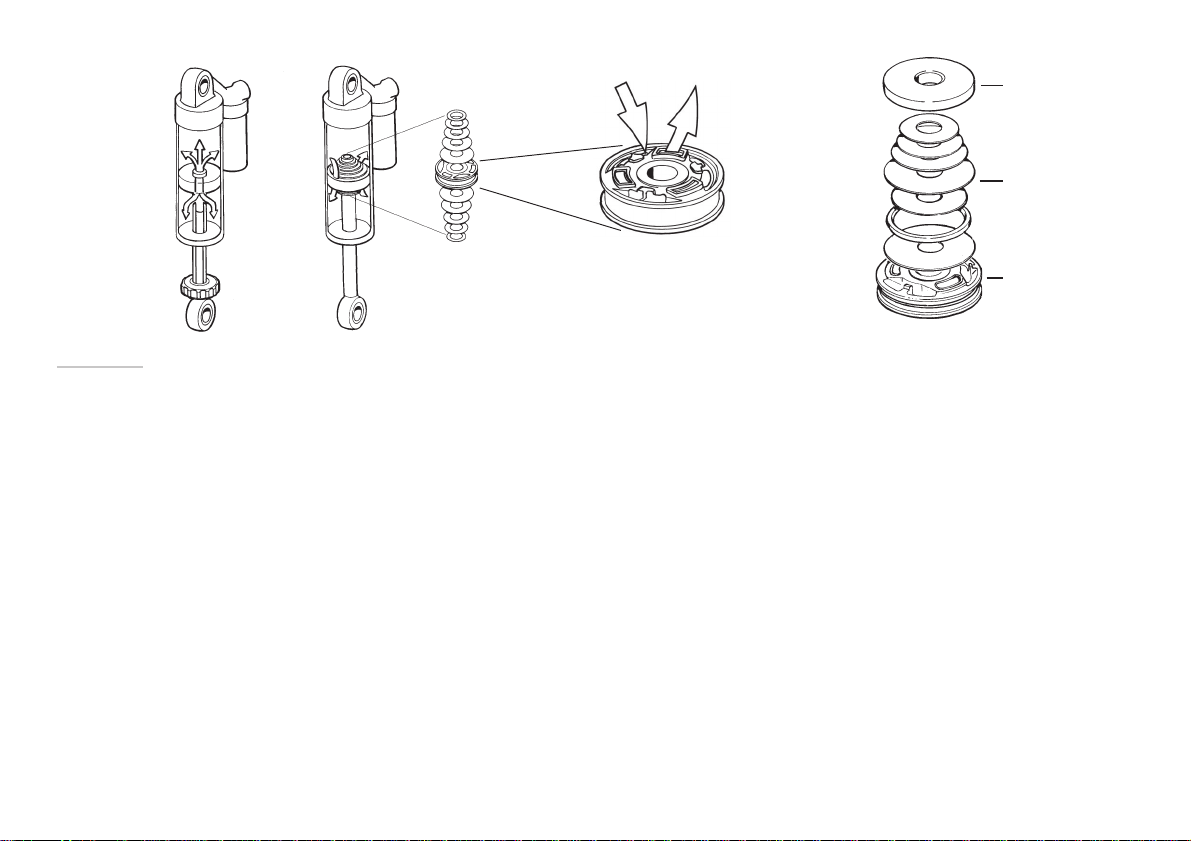
The function, in principle, is that fluid is forced
through needle valves at a low rate of flow (Fig.5)
and through a number of apertures in the piston
at a high rate of flow (Fig.6). The flow through these
apertures is regulated by shims (thin steel washers) that at high pressure are deflected to open for
the fluid (Fig.7). On some models the needle valves
can be set individually (illustration).
By altering the size of the shims-stack (ie,
number, thickness, diameter) (Fig.8) the
characteristics of the damping action can be varied
(this shall only be done by Öhlins authorized
service workshops).
4
Compression damping
When movement of the vehicle causes compression in the shock absorber, the fluid flows through
the needle valve (combined compression and return
valve) in the piston rod. If velocity of the piston is
high, ie, in the case of rapid compression, this will
not be sufficient and consequently the shims
underneath the piston will open to allow a greater
rate of flow.
The fluid that is displaced by the volume of the
piston rod is forced into the external fluid chamber
via a separate compression valve. Even this valve
is fitted with shims that open at high piston
velocity. The separating piston is displaced, thus
increasing the gas pressure.
Piston
8. Shim stack
Rebound damping
When the spring presses the shock absorber out
again, the fluid flows back through the needle
valve in the piston rod. The fluid flowing into the
chamber is forced by the pressure of the gas back
into the shock absorber via a separate non return
valve. If velocity of the piston is high, the shims
on top of the piston will also open to allow the
fluid to flow though.
Page 5
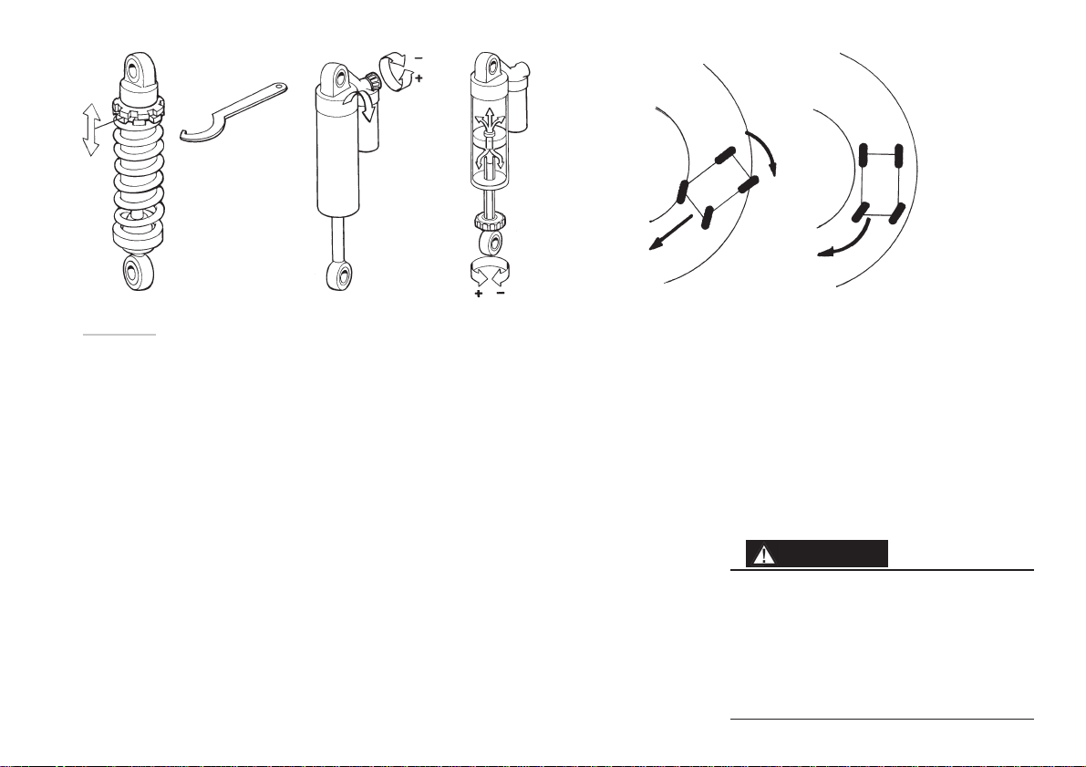
9. Adjustment possibilities 10. ATV, steering by sliding
1. 2. 3.
Settings
Basic settings
Always ensure that the basic setting made by
Öhlins is correct. It is adapted to the specific make
and model (in its original state) and for a rider of
average weight.
These adjustments are made to
optimize the suspension: (Fig.9)
1. SPRING PRELOAD is when you adjust the
spring to match your body weight and weight
of your equipment.
2. COMPRESSION DAMPING controls how fast
the shock absorber compresses when you hit
a bump.
3. REBOUND DAMPING controls how fast the
shock absorber returns to its normal position
after it has been compressed.
Steering by
sliding rear end
As an ATV has a rear axle without differential it is
forced to turn mostly by sliding (Fig.10). Therefore excessively good road holding capabilities
is undesirable. The rear end must be able to easily break loose to slide and the front wheels must
not have too sharp turning radius, as this could
cause the ATV to flip over.
The tires are also a very important factor to the
ATV's road holding capabilities. Pattern, sidewall
flexibility and air pressure affects these characteristics. Changing the dimensions of A-arms, swing
arm and linkage will also affect the vehicle's
abilities.
Because of this it is vital that the suspension is
adjustable. Any change of components will
demand different settings.
To complicate the situation, the technique and
skill of the driver will affect the perfomance of
the machine.
Normal vehical
steering by
turning the
front wheels in
the intended
direction
Therefore it is extremely hard to recommend
specific settings. The best recommendation is to
proceed by trial and error.
However, good understanding of suspension
design and function will give you the best chance
to take advantage of the adjustment possibilities.
This is why we only give basic and simple advice
on how to set the dampers/shock absorber.
Read the manual carefully and start your work.
The Öhlins shock absorber will give you all possibilities for fine adjustment to fit you personal desire.
WARNING!
1. ATVs are extremly depending on which kind of
tires are beeing used. Soft versus hard tires can
completely alter the road holding abilities. The
suspension must be tuned in after each change
of tires.
2. Every change in suspension geometry, i e
change of a-arms etc, must be followed by new
settings of the shock absorbers.
5
Page 6
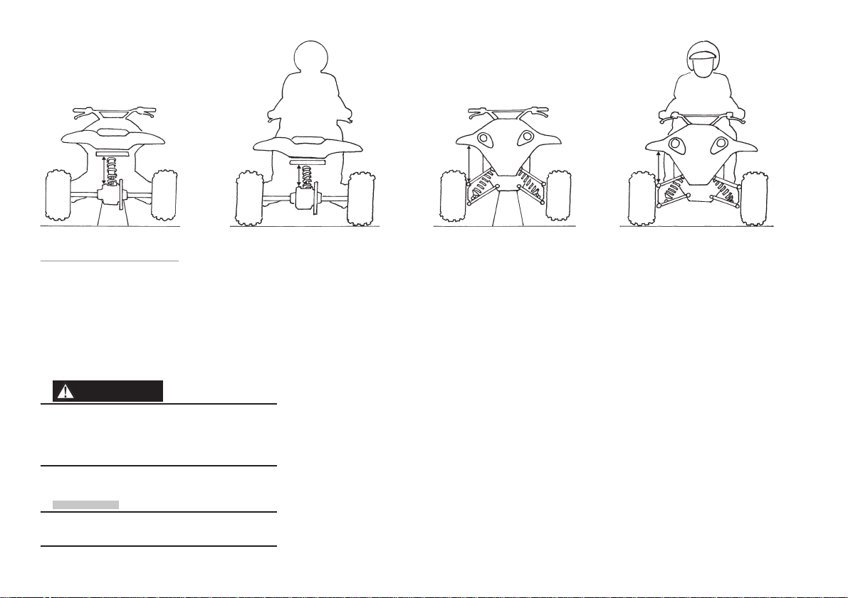
11. Measuring of ride height sag
A
Preload Adjustment
Setting the spring preload,
adjusting procedures:
By turning the rings on the shock absorber body
you can adjust the springs tension to suit your
weight. Hold the upper ring and adjust the lower
one to the desired position. Then lock with the
upper ring. To make this adjustment properly you
must measure the ride height sag (Fig.11).
WARNING!
Preload on the spring/springs is very important,
because it affects the height of the vehicle and
the wheel angles. Consequently, road holding
characteristics can be changed, even negatively.
NOTE!
For very light or very heavy drivers, spring change
may be needed to receive correct spring preload.
A
B
Rear end
1. Lift the rear wheels up off the ground.
2. With the wheels off the ground, measure the dis-
tance from the top center of the rear axle to a
point straight above it on the frame of the ATV. (A)
3. Wear all your riding gear. Sit on the seat with
your feet on the pegs in correct riding position. Have someone to repeat the measuring
procedure (B). The difference between the first
and the second measurement ride height sag
(A-B).
4. Adjust your spring preload so that your ride
height sag is within the limits below or are
according to the recommended settings in
your Mounting instructions.
B
Front end
Use the same procedure to measure the sag for
the front end. Adjust the spring preload to
recommended settings.
6
Page 7
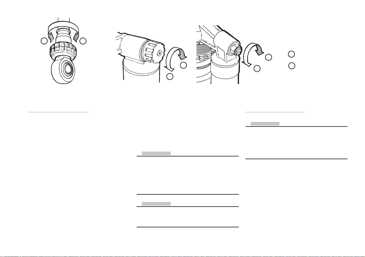
-
+
= more damping
+
+
-
+
= less damping
-
-
13. Compression damping adjusters12. Rebound damper adjuster
Setting the damping
The adjusting possibilities of the advanced Öhlins
shock absorbers facilitate fine setting. You can
optimize adjustments to suit your own vehicles
weight and equipment, your individual way of
driving and the condition of the road. To be able
to improve the road holding qualities it is of the
utmost importance that you fully understand the
functioning of the shock absorbers. Then you can
learn by trial and error how they affect the vehicle.
Depending on the model there are adjustments
for rebound damping and compression damping.
They have a normal right-hand thread. By turning clockwise they increase the damping action
and counterclockwise they reduce it, see illustrations above. The knobs has definite positions
with a noticeable “click”, so it is easy to count to
the right setting.
Rebound damping action affects the characteristics of the vehicle most. The setting knob is
located at the bottom on the piston rod (Fig.12).
It can be adjusted in about 40 steps.
Compression damping is set with a knob or a
screw on top of the external reservoir (Fig.13).
This can be adjusted in about 25 steps.
NOTE!
When making new adjustments it is easiest to go
fully closed and then count forward to the new
setting. The adjusting knobs should not be turned
in too hard. Use fingers only when possible. The
adjustment should be made when the shock
absorber is cold.
NOTE!
If no “click” is felt, the shock absorber must be
inspected by an authorized service workshop. It
could be due to incorrect or lack of gas pressure.
Setting your vehicle
NOTE!
Always begin with the basic settings recommended
by Öhlins. Always make notes, adjust in small steps
and make only one adjustment at a time.
Adjustments should be made in small steps (few
clicks) at a time.
By utilizing the adjustment possibilities you can
test by trial and error, and learn how they affect
your vehicle.
Always begin by test driving with all adjustments
at their basic setting. Choose a short run of varying
character, ie, long and sharp bends, hard and soft
bumps. Keep to the same run and make only one
adjustment at a time.
7
Page 8
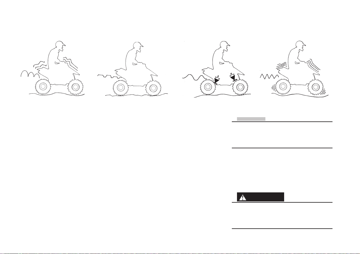
14. Rebound damping
15. Compression damping
• Unstable
• Loose
• Bouncy
Increase DecreaseIncrease
Start with the rebound damping (Fig.14)
If the vehicle feels unstable, loose and rather bouncy
then the rebound damping should be increased.
Begin by turning the adjusting knob 4 steps (clicks)
clockwise, according to page 7. Test run again and
adjust two steps back if it feels too hard and bumpy.
If the vehicle is hard and bumpy, especially over a
series of bumps, then the rebound damping should
be reduced. Turn counter-clockwise 4 steps, test
run and make any necessary correction by 2 steps.
• Hard
• Bumpy
• Soft
• Low
• Bottom
Reduce
Compression damping (Fig.15)
If the vehicle feels soft, has low riding position
and a tendency to bottom easily in long dips then
the compression damping should be increased.
Screw clockwise 4 steps and test run again. If
this was too much then turn back two steps
(counter-clockwise).
If the vehicle feels harsh and has hard resilience, e.g., over changes in the riding surface,
then the compression damping must be reduced.
Turn anticlockwise 4 steps. Test run and make
any necessary correction to two steps.
When you have sufficient feel of the vehicle
then you can make further fine adjustments. It is
feeling and experience that counts.
• Harsh
• Hard
NOTE!
Ensure that the springs are properly preloaded before attempting to make any adjustments. A simple
rule is that increased preload of the spring should
be followed by an increase of rebound damping.
When you feel that you have achieved an improvement, go back to where you started and
check once more. Be observant of other relevant
factors such as tires, temperature, etc. Test run
to make sure whether further fine adjustment
should be made.
WARNING!
Never alter gas pressure. Special purpose charging equipment and access to a nitrogen source
is required. The gas pressure should normally
never be altered.
8
Page 9
3 4
1
16. Lift the bump rubber
and clean the area below. 17. Inspection points:
Inspection and maintenance
Clean the shock absorbers externally with a soft
detergent . Use compressed air . Be careful that
all dirt and debris is removed.
Lift the bump rubber and clean the area below
(Fig.16).
Keep the shock absorbers clean and always
spray them with oil (QS 14, WD40 or CRC 5-56
or similar) after washing the vehicle.
CAUTION!
Never use detergents that can damage the surfaces of the shock absorber. Use of thinner and
brake cleaner will dry the surfaces too much..
3
2
5
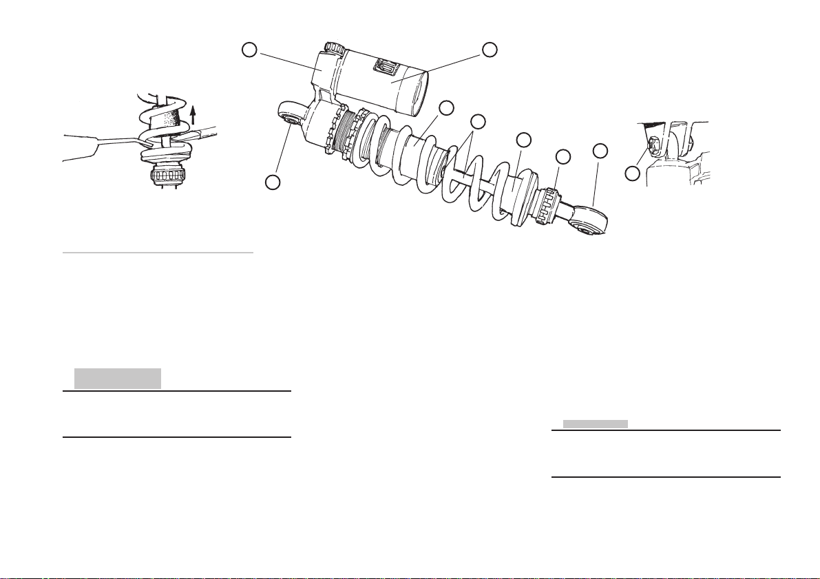
Inspection points: (Fig.17)
1. Check ball joints for possible excessive play.
2. Check the piston shaft for leakage and damage.
3. Check the shock absorber body and for
external damages.
4. Check the external reservoir for damages that
can restrict the floating piston from moving freely.
5. Excessive wear of rubber components
6. Fastening to the vehicle
Preventive maintenance and regular inspection
reduces the risk of functional disturbance. If there
is any need for additional service, please get in
touch with an authorised Öhlins service workshop.
There they have the necessary tools and knowhow for whatever you need.
1
5
6
Recommended inspection and
maintenance intervals:
Normal use 2 - 3 times a year
Race track Every ten hours
Once a year, general:
Change shock absorber oil.
Use Öhlins shock absorber oil only.
NOTE!
Make certain that your shock absorber are always
filled with Öhlins High performance shock absorber oil
9
Page 10
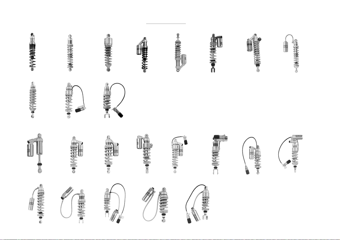
Product guide
36E 36D 36K 36P 36PR 36PRCL 36PRCLB 36H
46ER/DR 46ERS/DRS 46DRLS
46PRCW 46PRC 46PRCL 46PRCLB 46PRCS 46PRCS 46PRCLS 46PRCLS
46PRCQ Vertical Horizontal Vertical Horizontal
46HR 46HRC 46HRCS 46HRCL 46HRCLS
10
New!
Page 11
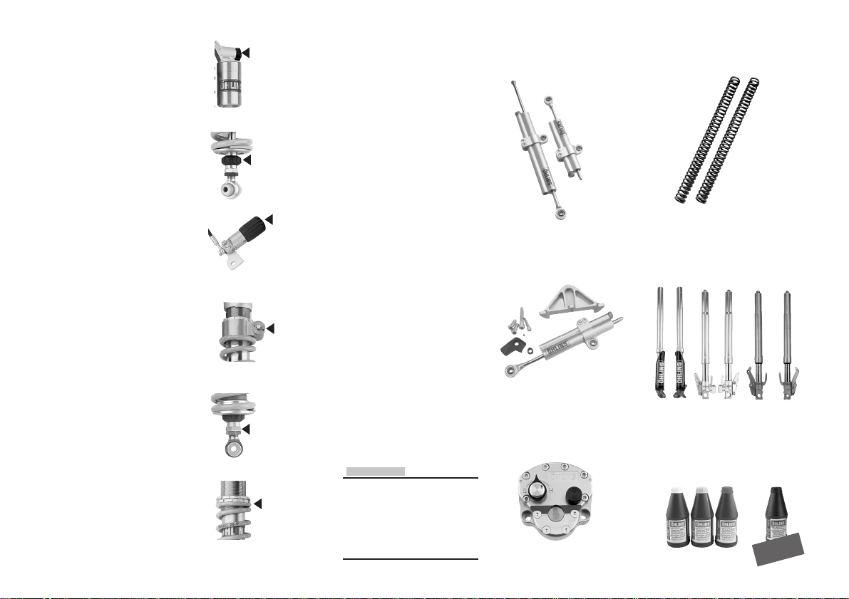
Shock absorber type
36, 46
Piston diameter in mm.
E
Emulsion type of shock
absorber.
D
De Carbon type of shock
absorber with internal reservoir in the main body.
P
De Carbon type of shock
absorber with external
”piggy back” reservoir.
H
De Carbon type of shock
absorber with hose
mounted external reservoir.
W
Shock absorber delivered
without spring.
K
Emulsion type of shock
absorber for cruiser bikes.
Q
Progressive damping shock
absorber with two pistons.
Compression
Rebound
Spring preload
(hydraulic)
Spring preload
(hydraulic)
Length
Spring preload
(C-spanner)
Adjustment features
C
Adjustable compression
damping.
Adjuster wheel on the
reservoir.
R
Adjustable rebound damping.
Adjuster wheel on the piston
shaft above the end eye.
S
Hose mounted hydraulic
spring preload adjuster.
Adjuster wheel on the hose.
B
Integrated hydraulic spring
preload adjuster.
Adjuster wheel on the
adjuster.
L
Adjustable length.
Adjuster nuts above the
end eye.
NOTE!
Your shock absorber may look different from the once pictured.
On type 46P the compression adjustment knob sometimes is a screw.
The reservoir could be angled to fit
your bike and a horizontal reservoir
is used on some models.
Steering dampers Front fork springs
Road & Track
Road & Track, MX & Enduro
Front forks
Road & Track kits
MX & Enduro
MX & Enduro, Road & Track
Superbike & RR
Front fork fluids
Road & Track, MX & Enduro
New!
11
Page 12

Notes
12
Öhlins Racing AB, Box 722, S-194 27 Upplands Väsby, Sweden.
Phone +46 8 590 025 00, fax +46 8 590 025 80.
E-mail: [email protected]
www.ohlins.com
07235-01, Issued 01 06 21. 600 ex.
 Loading...