

10 23912 51
Stand 04.201
8 (16/016)
Bedienungsanleitung
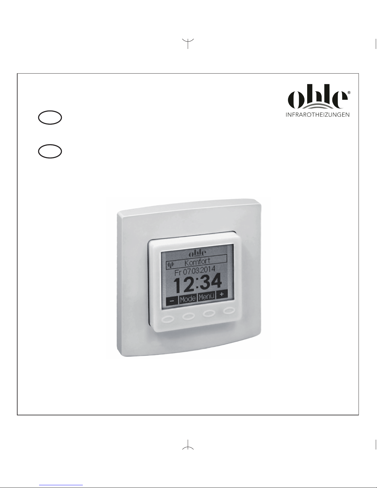
Thermostat-Sender mit Masterfunktion, Unterputz
Operating Instructions
for thermostat transmitter with master function,
flush-mounted
D
GB
Funktionstyp 010
Function type 010

2
11. Sicherheitshinweis . . . . . . . . . . . . . . . . . . . . . . . . . . . . . . . . . . . . . . . . . . . . . 03
12. Anwendung . . . . . . . . . . . . . . . . . . . . . . . . . . . . . . . . . . . . . . . . . . . . . . . . . . 03
13. Hinweise zur Bedienung . . . . . . . . . . . . . . . . . . . . . . . . . . . . . . . . . . . . . . . . 03
14. Regelbetrieb . . . . . . . . . . . . . . . . . . . . . . . . . . . . . . . . . . . . . . . . . . . . . . . . . . 03
14.1 Temporäre Solltemperatureinstellung . . . . . . . . . . . . . . . . . . . . . . . . . . . . . . 04
14.2 Auswahl der Betriebsart / Frostschutz . . . . . . . . . . . . . . . . . . . . . . . . . . . . . . 05
15. Hauptmenü . . . . . . . . . . . . . . . . . . . . . . . . . . . . . . . . . . . . . . . . . . . . . . . . . . .06
15.1 Untermenü Party . . . . . . . . . . . . . . . . . . . . . . . . . . . . . . . . . . . . . . . . . . . . . . 08
15.2 Untermenü Urlaub . . . . . . . . . . . . . . . . . . . . . . . . . . . . . . . . . . . . . . . . . . . . . 08
15.3 Einstellen der Uhrzeit / des Datums . . . . . . . . . . . . . . . . . . . . . . . . . . . . . . . 09
15.4 Eingabe der Solltemperaturen . . . . . . . . . . . . . . . . . . . . . . . . . . . . . . . . . . . . 09
15.5 Eingabe der Tagesprogramme . . . . . . . . . . . . . . . . . . . . . . . . . . . . . . . . . . . 10
15.6 Information . . . . . . . . . . . . . . . . . . . . . . . . . . . . . . . . . . . . . . . . . . . . . . . . . . . 12
15.7 Einstellungen . . . . . . . . . . . . . . . . . . . . . . . . . . . . . . . . . . . . . . . . . . . . . . . . . 12
16. Expertenmenü . . . . . . . . . . . . . . . . . . . . . . . . . . . . . . . . . . . . . . . . . . . . . . . . 15
17. Montage/Anschluss . . . . . . . . . . . . . . . . . . . . . . . . . . . . . . . . . . . . . . . . . . . . 16
18. Erstinbetriebnahme . . . . . . . . . . . . . . . . . . . . . . . . . . . . . . . . . . . . . . . . . . . . 16
19. Anschluss- und Maßzeichnung . . . . . . . . . . . . . . . . . . . . . . . . . . . . . . . . . . . 17
10. Technische Daten . . . . . . . . . . . . . . . . . . . . . . . . . . . . . . . . . . . . . . . . . . . . . 19
11. Sensorkennlinien . . . . . . . . . . . . . . . . . . . . . . . . . . . . . . . . . . . . . . . . . . . . . . 20
12. Zubehör . . . . . . . . . . . . . . . . . . . . . . . . . . . . . . . . . . . . . . . . . . . . . . . . . . . . . 20
13. Gewährleistung . . . . . . . . . . . . . . . . . . . . . . . . . . . . . . . . . . . . . . . . . . . . . . . 20
Übersicht Bedienungsanleitung
D

3
Dieser Unterputz-Funk-Raumtemperaturfühler (Sender) mit zeitgesteuerter Energiesparfunktion,
wurde speziell zur Temperaturerfassung in Wohn-, Büro- und Hotelräumen entwickelt und wird
gemeinsam mit einem oder mehreren Funk-Temperaturreglern (Empfänger) betrieben. Die
Gesamteinheit aus Funk-Raumtemperaturfühler und Funk-Temperaturregler, dient so der
Einzelraum-Temperaturregelung. Anwendung findet die Funk-Raumtemperaturregelung vorwie
gend
im Sanierungsbereich, bei Heizungsanlagenerweiterungen, bei denen aufwändige
Aufriss- und
Putzarbeiten zur Elektro-Leitungsverlegung vermieden werden sollen oder in modernen
Bürokomplexen, bei denen die Flexibilität der Raumgestaltung im Vordergrund steht. Für andere, vom
Hersteller nicht vorherzusehende Einsatzgebiete, sind die dort gültigen Sicherheitsvorschriften zu
beachten.
Eignung hierfür siehe Punkt 13. Gewährleistung.
2. Anwendung
Das Gerät besitzt 4 Sensortastflächen, die durch die geprägten Ovale gekennzeichnet sind. Ihre
Funktion kann sich abhängig von der Bedienung verändern und wird jeweils im Display oberhalb der
Ovale angezeigt. Das Gerät verfügt über eine Schutzfunktion, die ein unbeabsichtigtes Betätigen
der Tastflächen verhindert. Die Funktion wird 20 Sekunden nach der letzten Berührung einer
Tastfläche aktiv und wird durch Berühren einer beliebigen Tastfläche für ca. 2 Sekunden wieder deaktiviert (siehe Hinweis im Display). Weiterhin sind die Menü- und Einstellfunktionen für den Heiz- bzw.
Kühlbetreib nur verfügbar wenn der entsprechende Reglertyp eingestellt wurde.
3. Hinweise zur Bedienung
Dieses Gerät darf nur durch eine Elektrofachkraft geöffnet und gemäß dem entsprechenden
Schaltbild auf dem Gehäuse oder in der Bedienungsanleitung installiert werden. Dabei sind die
bestehenden Sicherheitsvorschriften zu beachten.
Achtung! Der Betrieb in der Nähe von Geräten, welche nicht den EMV-Bestimmungen entsprechen,
kann zur Beeinflussung der Gerätefunktionen führen. Nach der Installation ist der Betreiber, durch die
ausführende Installationsfirma, in die Funktion und Bedienung der Regelung einzuweisen. Die
Bedienungsanleitung muss für Bedien- und Wartungspersonal an frei zugänglicher Stelle aufbewahrt
werden.
1. Sicherheitshinweis
0
0
4
Nach ca. 5 Sekunden ohne Tastenbetätigung erfolgt eine automatische Rückkehr in den
Regelbetrieb. Der veränderte Solltemperaturwert wird dabei übernommen. Der eingestellte
Solltemperaturwert gilt, bis die Betriebsart gewechselt wird (manuell oder automatisch nach
Schaltuhr), die Urlaubs- oder Partyfunktion gestartet bzw. beendet wird oder das Expertenmenü aufgerufen wird.
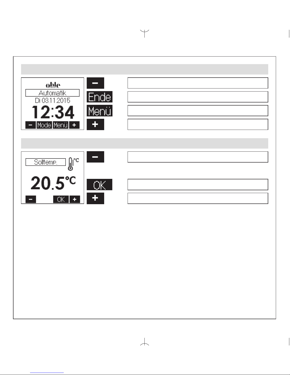
4. Regelbetrieb
temporäre Solltemperatureinstellung siehe 4.1
Auswahl der Betriebsart siehe 4.2
Hauptmenü siehe 5.
temporäre Solltemperatureinstellung siehe 4.1
4.1 Temporäre Solltemperatureinstellung
Solltemperatur – 0,5K
Übernahme der Werte / Rückkehr zum Regelbetrieb
Solltemperatur + 0,5K

5
4.2 Auswahl der Betriebsart / Frostschutz
Eine Betätigung der Tastfläche führt zu einem Wechsel der Betriebsart in der dargestellten
Reihenfolge:
– Automatik (automatische Regelung nach eingestelltem Tagesprogramm siehe 5.4 / 5.5)
– Komfort (dauerhafte Regelung auf Komfort-Temperatur – siehe 5.4)
– ECO (dauerhafte Regelung auf ECO-Temperatur – siehe 5.4)
– Bereitschaft (Frostschutz)
In der Betriebsart „Bereitschaft“ wird bei Unterschreitung einer Temperatur von ca. 5°C am internen
Sensor bzw. am aktivierten externen Sensor die Frostschutzfunktion ausgelöst.
Durch diese Frostschutzfunktion werden ein Auskühlen und dadurch verursachte Frostschäden im
Raum vermieden.
6
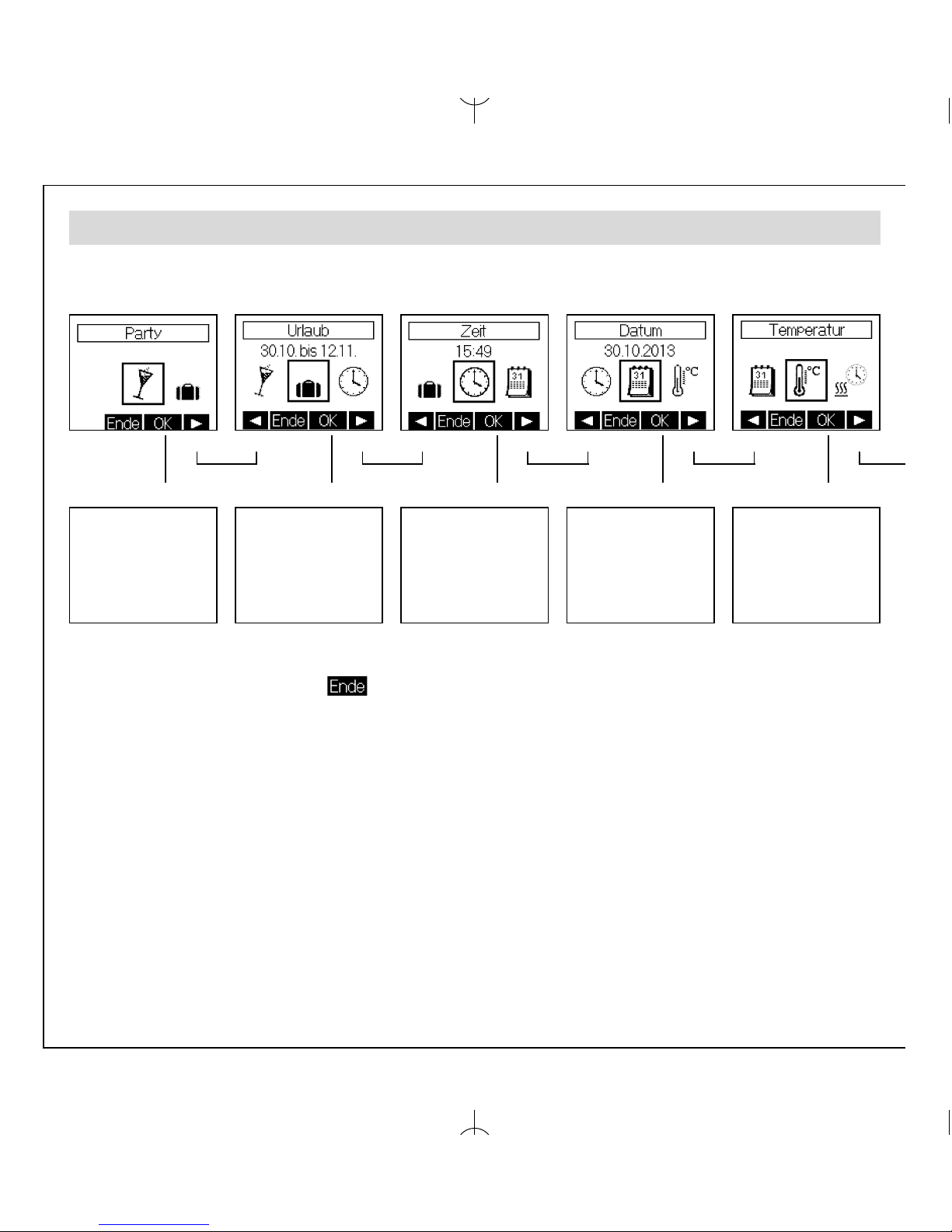
5. Hauptmenü
Das Hauptmenü wird mit Taste beendet.
Untermenü
Party
siehe 5.1
Untermenü
Urlaub
siehe 5.2
Untermenü
Uhrzeit
siehe 5.3
Untermenü
Datum
siehe 5.3
Untermenü
Temperatur
siehe 5.4
쑼쑼쑼쑼쑼
쑼쑼 쑼쑼 쑼쑼 쑼쑼 쑼

7
5. Hauptmenü
쑼
Untermenü
Tagesprogramm
Heizen
siehe 5.5
Untermenü
Tagesprogramm
Kühlen
siehe 5.5
Information
siehe 5.6
Untermenü
Einstellungen
siehe 5.7
Aufruf
Expertenmenü
siehe 6
Ist der Regler als Heizen/Kühlen-Regler konfiguriert (siehe 6.2), können separate Tagesprogramme
für den Heizbetrieb und Kühlbetrieb erstellt werden. Ist der Regler als Heizen-Regler oder KühlenRegler konfiguriert, steht nur die jeweilige Einstellfunktion zur Verfügung.
쑼쑼쑼쑼쑼쑼쑼
쑼쑼쑼쑼
8
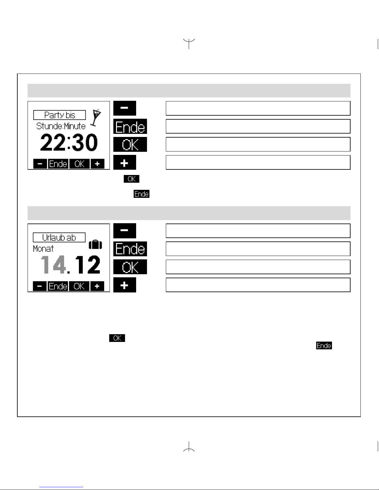
5.1 Untermenü Party
Partydauer – 15 Minuten
Abbruch der Eingabe / Rückkehr ins Hauptmenü
Hauptmenü siehe 5.
Urlaubsbeginn Monat - 1
Abbruch der Eingabe / Rückkehr ins Hauptmenü
Wechsel zu Urlaubsbeginn Tag
Urlaubsbeginn Monat + 1
Mit Betätigung der Tastfläche wird die Partyfunktion gestartet. Bei Erreichen der eingegebenen Zeit erfolgt automatisch ein Wechsel in die vorherige Betriebsart. Die Partyfunktion kann
durch Betätigung der Tastfläche jederzeit beendet werden.
Partydauer + 15 Minuten
5.2 Untermenü Urlaub
Die Eingaben „Tag Urlaubsbeginn“, „Monat Urlaubsende“ und „Tag Urlaubsende“ erfolgen analog
zur Eingabe „Monat Urlaubsbeginn“. Anschließend erfolgt die Eingabe der Urlaubstemperaturdifferenz zum Komfortsollwert. Es können jeweils Werte von +/-1K bis +/-6K eingegeben werden
oder die Heizung / Kühlung während der Urlaubsdauer abgeschaltet werden. Der Frostschutz bleibt
dabei erhalten (Werkseinstellung Heizen -3K, Kühlen +3K).
Mit Betätigung der Taste werden die Werte übernommen. Bereits eingestellte Urlaubsdaten
können verworfen werden, indem das Menü „Urlaub“ erneut aufgerufen und die Eingabe
mit abgebrochen wird.
9
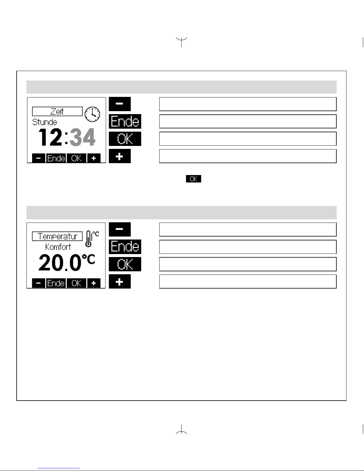
5.3 Einstellen der Uhrzeit / des Datums
Die Eingabe der Minuten erfolgt analog zur Eingabe der Stunden. Wurde die Einstellung der
Minuten geändert, erfolgt mit Betätigung der Taste die Übernahme der Werte sowie die
Rückkehr ins Hauptmenü. Gleichzeitig werden die Sekunden auf 0 gesetzt. Die Einstellung des
Datums (Jahr, Monat, Tag) erfolgt analog zur Eingabe der Uhrzeit.
Stunde - 1
Abbruch der Eingabe / Rückkehr ins Hauptmenü
Wechsel zur Eingabe Minute
Stunde + 1
Komforttemperatur – 0,5K
Abbruch der Eingabe / Rückkehr ins Hauptmenü
Übernahme des Wertes, Wechsel zu Eingabe ECO-Temperatur
Komforttemperatur + 0,5K
5.4 Eingabe der Solltemperaturen
Werkseinstellung: 20°C
Auf diese Temperatur wird während der Komfort-Zeiten geregelt.
10
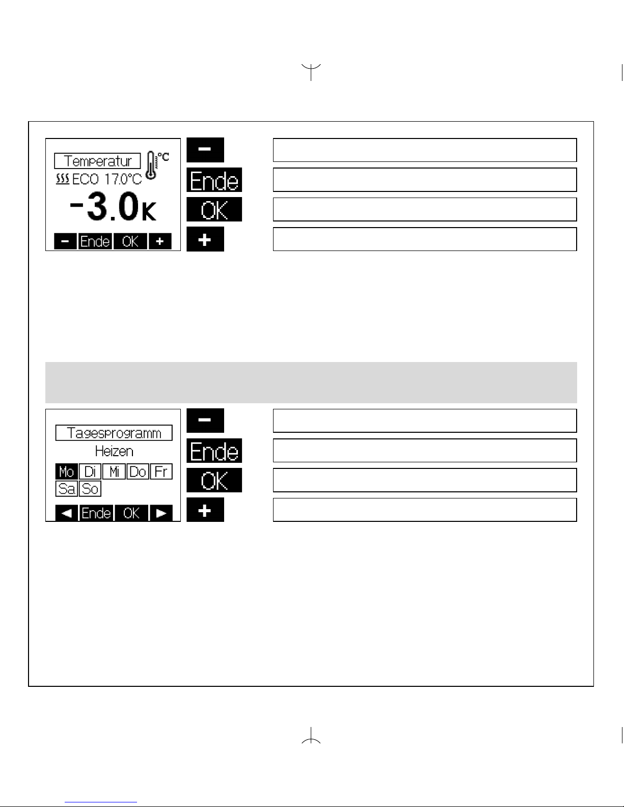
Die Eingabe der ECO-Temperaturen erfolgt analog zur Eingabe der Komforttemperatur, jedoch
werden die ECO-Temperaturen als Differenz zur Komforttemperatur angegeben. Für den Heizbetrieb ist eine Absenkung um 1K … 6K, bzw. der Frostschutzbetrieb einstellbar.
Werkseinstellung: -3K
Für den Kühlbetrieb ist eine Anhebung um 1K … 6K, bzw. „Kühlung aus“ einstellbar.
Werkseinstellung: +3K
In der zweiten Zeile ist die, sich ergebende Solltemperatur ablesbar.
ECO-Temperaturdifferenz - 1K
Abbruch der Eingabe / Rückkehr ins Hauptmenü
Übernahme des Wertes
ECO-Temperaturdifferenz + 1K
Wochentag zurück
Abbruch der Eingabe / Rückkehr ins Hauptmenü
Wechsel zur Eingabe Komfort- und ECO-Zeiten
Wochentag vor
5.5 Eingabe der Tagesprogramme
Auswahl des Wochentages
11
5.5 Eingabe der Tagesprogramme
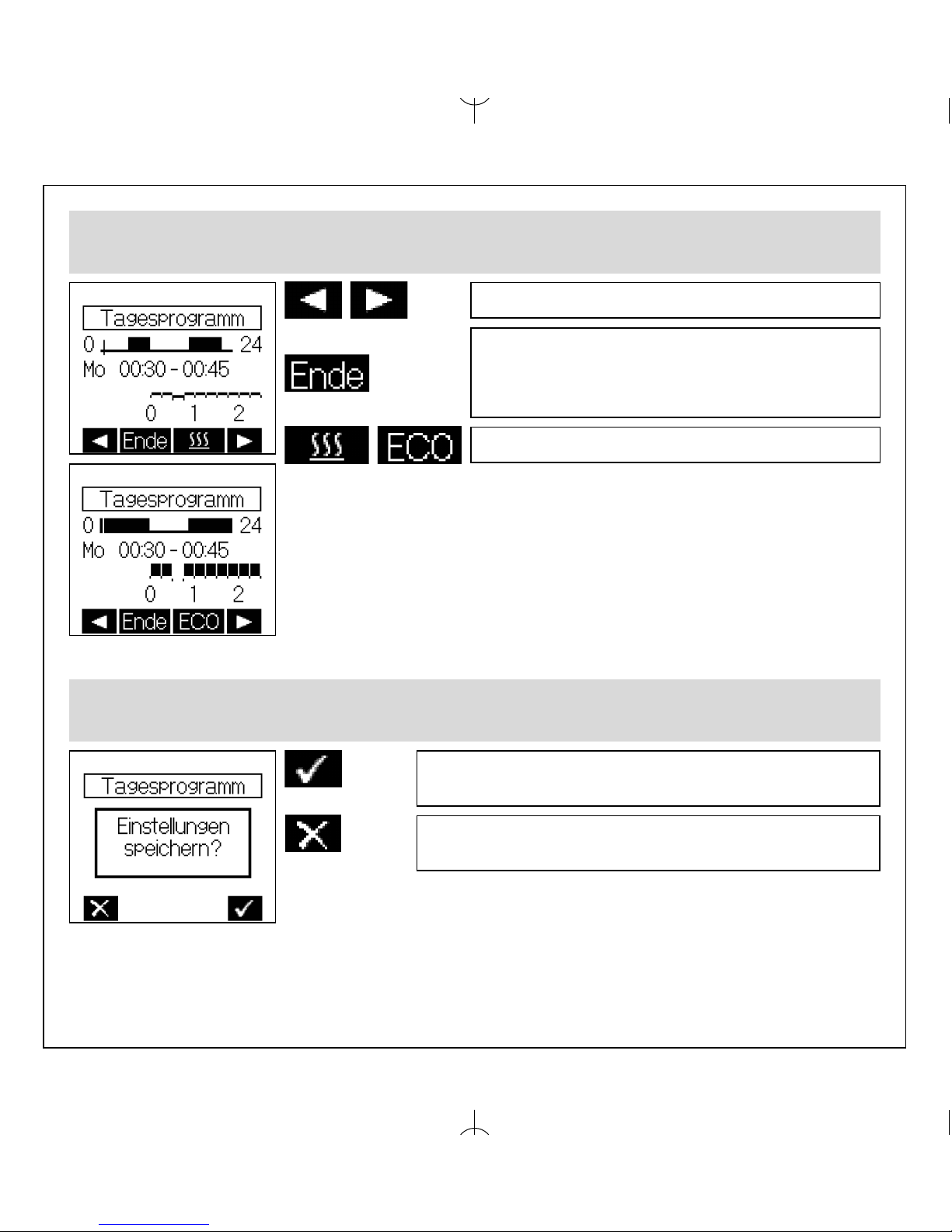
Auswahl der Komfort- ( 쎱 ) bzw. ECO-Zeiten ( _ )
Werkseinstellung Komfortzeiten „Heizen“:
Montag bis Freitag: 05:00 … 9:00 /16:00 … 22:00
Samstag und Sonntag: 06:00 … 22:00
Werkseinstellung Komfortzeiten „Kühlen“:
Montag bis Freitag: 00:00 … 9:00 /16:00 … 00:00
Samstag und Sonntag: 00:00 … 24:00
Position + / – 15 Minuten
Beenden der Eingabe. Wurden keine
Änderungen vorgenommen erfolgt eine
Rückkehr zur Auswahl des Wochentags,
sonst Wechsel zur Bestätigung der Eingaben
Wechsel zwischen Komfort- und ECO-Zeiten
5.5 Eingabe der Tagesprogramme
Bestätigung der Eingabe
Speichern der Eingabe, Wechsel ins Menü zum
Kopieren der Eingabe für andere Wochentage
Abbruch der Eingabe,
Rückkehr zur Auswahl des Wochentages
12
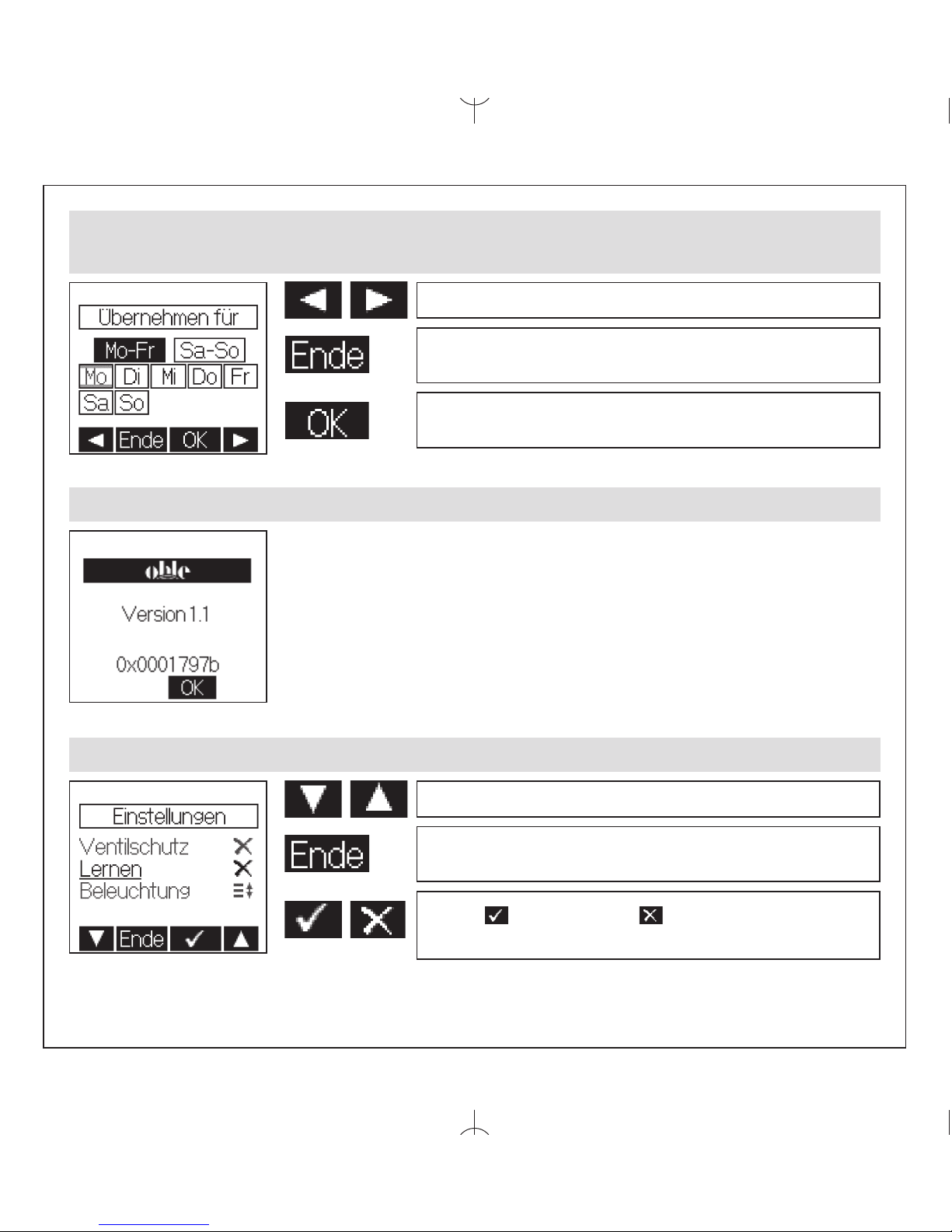
5.5 Eingabe der Tagesprogramme
Übernahme der Eingabe für andere Wochentage
Auswahl vor / zurück
Keine Übernahme der Eingabe,
Rückkehr zur Auswahl des Wochentages
Übernahme der Eingabe für den (die)
ausgewählten Wochentag(e).
5.6 Information
Anzeige QR-Code:
Wenn diese Funktion vorhanden ist, können über die im
QR-Code kodierte Internetadresse weitere Informationen zu diesem
Regler abgerufen werden.
5.7 Einstellungen
Auswahl abwärts / aufwärts
Abbruch der Eingabe,
Rückkehr ins Hauptmenü
Aktivieren bzw. Deaktivieren der
ausgewählten Funktion

13
5.7 Einstellungen
Folgende Funktionen sind verfügbar:
5.7.1.Tastensperre
Die Tastensperre wird ca. 2 Minuten nach der letzten Berührung einer Tastfläche aktiv und das
Schlüsselsymbol wird im Display angezeigt. Um die Tastflächen wieder zu aktivieren, muss eine
beliebige Tastfläche ca.10 Sekunden lang berührt werden.
Werkseinstellung: Aus
5.7.2. Automatische Sommer-/Winterzeitumstellung
Die vereinheitlichte Sommerzeit in der Europäischen Union gilt vom letzten Sonntag im März um 2.00
Uhr MEZ bis zum letzten Sonntag im Oktober um 3.00 Uhr MESZ (Richtlinie 2000/84/EG des
Europäischen Parlaments und des Rates). Zu diesen Terminen ändert dieser Temperaturregler automatisch die Zeit. Für Zeitumstellungen zu anderen Terminen oder Regionen ohne Zeitumstellung,
kann die automatische Sommer-/Winterzeitumstellung deaktiviert werden.
Werkseinstellung: Ein
5.7.3. Ventilschutzfunktion
Der Ventil- und Pumpenschutz dient der Verhinderung des Festkorrodierens des Ventilsitzes und
/ oder der Pumpen bei langen Stillstandszeiten. Bei Warmwasser-heizungen wird die Aktivierung des
Ventilschutzes empfohlen. Ist der Ventil- und Pumpenschutz aktiviert, steuert der Regler montags
11.00 Uhr das Ventil und / oder eine Umwälzpumpe einmalig für 5 Minuten an.
Werkseinstellung: Aus
5.7.4. Lernfunktion
Die Lernfunktion dient dem selbstständigen Erreichen des Komfort-Temperaturwertes „Heizen“ zum
eingestellten Zeitpunkt. Der vorgezogene Umschaltzeitpunkt von ECO auf Komfort-Temperatur stellt
sich selbsttätig ein. Die Aufheizzeit variiert je nach Heizleistung und Außentemperatur. Die
Lernfunktion ist nur im Heizbetrieb verfügbar.
Werkseinstellung: Aus
5.7.5. Displaybeleuchtung
Die Dauer der Displaybeleuchtung ist in folgenden Schritten einstellbar:
1. während der Bedienung und ca.10 Sekunden nach der letzten Berührung einer Tastfläche
2. zusätzlich zu 1. während der Komfort-Zeiträume „Heizen“ und der Partyfunktion
3. zusätzlich zu 1. während der Komfort-Zeiträume „Heizen“ und „Kühlen“ sowie der Partyfunktion
4. zusätzlich zu 1. während der Komfort-Zeiträume „Kühlen“ und der Partyfunktion
5. permanente Beleuchtung
Werkseinstellung: 10 Sekunden

14
5.7.6 Anzeigeinhalt
Es kann zwischen folgenden Anzeigeinhalten gewählt werden:
1. Zeit
2. Temperaturen
3. Zeit & Temperaturen im Wechsel
Werkseinstellung: Zeit & Temperaturen im Wechsel
5.7.7 An- und Abmelden
1. Mit der Anlernfunktion wird ein Funk-Raumtemperaturfühler (Sender) dem jeweiligen FunkTemperaturregler (Empfänger) zugeordnet. Dazu ist der Funk-Temperaturregler (Empfänger) in den
Anlernmodus zu bringen. Mit der Taste wird das Senden der Anlernkennung für 10 Sekunden
gestartet. Dabei blinkt das Funksymbol auf der Anzeige. Zur Reaktion des Empfängers auf die
Anlernkennung, lesen Sie bitte die Bedienungsanleitung des jeweiligen Empfängers.
2. Diese Funktion dient dem Abmelden des Funk-Raumtemperaturfühlers (Sender) von einem FunkTemperaturregler (Empfänger). Mit der Taste wird das Senden der Ablernkennung für 10
Sekunden gestartet. Dabei blinkt das Funksymbol auf der Anzeige. Um den FunkRaumtemperaturfühler abzumelden, muss in dieser Zeit am Empfänger ebenfalls der Ablernmodus
aktiviert werden. Zur Aktivierung des Ablernmodus am Empfänger, lesen Sie bitte die
Bedienungsanleitung des jeweiligen Gerätes.
5.7.8 Werkseinstellungen
Hier werden folgende Inhalte auf die Werkseinstellungen zurückgesetzt:
– die Tagesprogramme,
– der Komfort-Temperatursollwert,
– die ECO-Temperaturdifferenzwerte („Heizen“ / „Kühlen“),
– eingegebene Urlaubstermine sowie der Urlaubs-Temperatursollwert,
– die Betriebsart auf „Automatik nach Tagesprogramm“,
– der Anzeigeinhalt,
– die Beleuchtungsdauer,
– der gelernte Temperaturgradient (siehe 5.7.4. Lernfunktion).

15
Werkseinstellung 90% intern
Wichtung intern +10%
Abbruch der Eingabe
Übernahme des Wertes, Rückkehr ins Expertenmenü
Wichtung extern +10%
6. Expertenmenü
Das Expertenmenü wird im Hauptmenü unter Punkt „Einstellungen” (siehe 5.) durch eine ca. 10
Sekunden lange Betätigung der rechten Tastfläche aufgerufen.
Achtung! In diesem Menü werden Regelungseinstellungen vorgenommen, die nur durch eine qualifizierte Heizungs- oder Elektrofachkraft durchgeführt werden dürfen. Einstellungen im
Expertenmodus können nicht auf die Werkseinstellungen zurückgesetzt, sondern müssen bewusst
eingestellt werden.
Folgende Einstellungen sind möglich:
6.1 Sprache
Es kann zwischen der deutschen, der englischen, der französischen, der niederländischen, der polnischen, der tschechischen oder der russischen Sprache gewählt werden.
6.2 Reglertyp
Es kann zwischen Heizen-Regler, Heizen / Kühlen-Regler oder Kühlen-Regler gewählt werden.
6.3 externer Sensor
An dieses Gerät sind externe Temperatursensoren (NTC) mit einem Widerstandswert von
2 k액,3 k액, 10 k액, 12 k액, 15 k액, 33 k액, oder 47 k액 bei 25°C anschließbar. Der verwendete
Temperatursensor muss hier ausgewählt werden.
(Werkseinstellung: kein externer Sensor angeschlossen).
6.4 Wichtung zwischen internen und externen Sensor
(nur verfügbar wenn ein externer Sensor ausgewählt wurde)
6.5 Messkorrektur
Der gemessene Temperaturwert kann, für den internen sowie den externen Temperatursensor einzeln (in Abhängigkeit der Konfiguration) im Bereich von -5K bis +5K in 0,1K- Schritten angepasst
werden. Dabei wird im Display der aktuelle, unkorrigierte Messwert für den jeweiligen Sensor angezeigt (Werkseinstellung 0.0).

16
Der Regler ist zur Montage in die Unterputzdose bestimmt und darf nicht direkt Wärme- oder
Kältequellen ausgesetzt werden. Es ist darauf zu achten, dass der Regler auch rückseitig keiner
Fremderwärmung oder -kühlung, z.B. bei Hohlwänden durch Zugluft oder Steigleitungen, ausgesetzt
wird. Der Regler ist auf die Tapete / den Wandbelag zu montieren. Das Gerät mit dem 50 x 50 mm
Gehäusedeckel ist mittels Zwischenrahmen der
Schalterhersteller nach DIN 49075 in nahezu alle
Schalterprogramme integrierbar. Das Gerät mit dem
55 x 55 mm Gehäusedeckel ist ebenfalls für diverse
Schalterprogramme geeignet. Bei Mehrfachrahmen ist der
Regler immer an unterster Stelle zu montieren.
Achtung, vor Installation Netzspannung allpolig
abschalten! Der elektrische Anschluss erfolgt gemäß
Anschluss-Schaltbild Punkt 9. Hierzu können die
Steckklemmen komfortabel vorverdrahtet und bei der
Montage in die Unterputzdose mit dem Regler verbunden
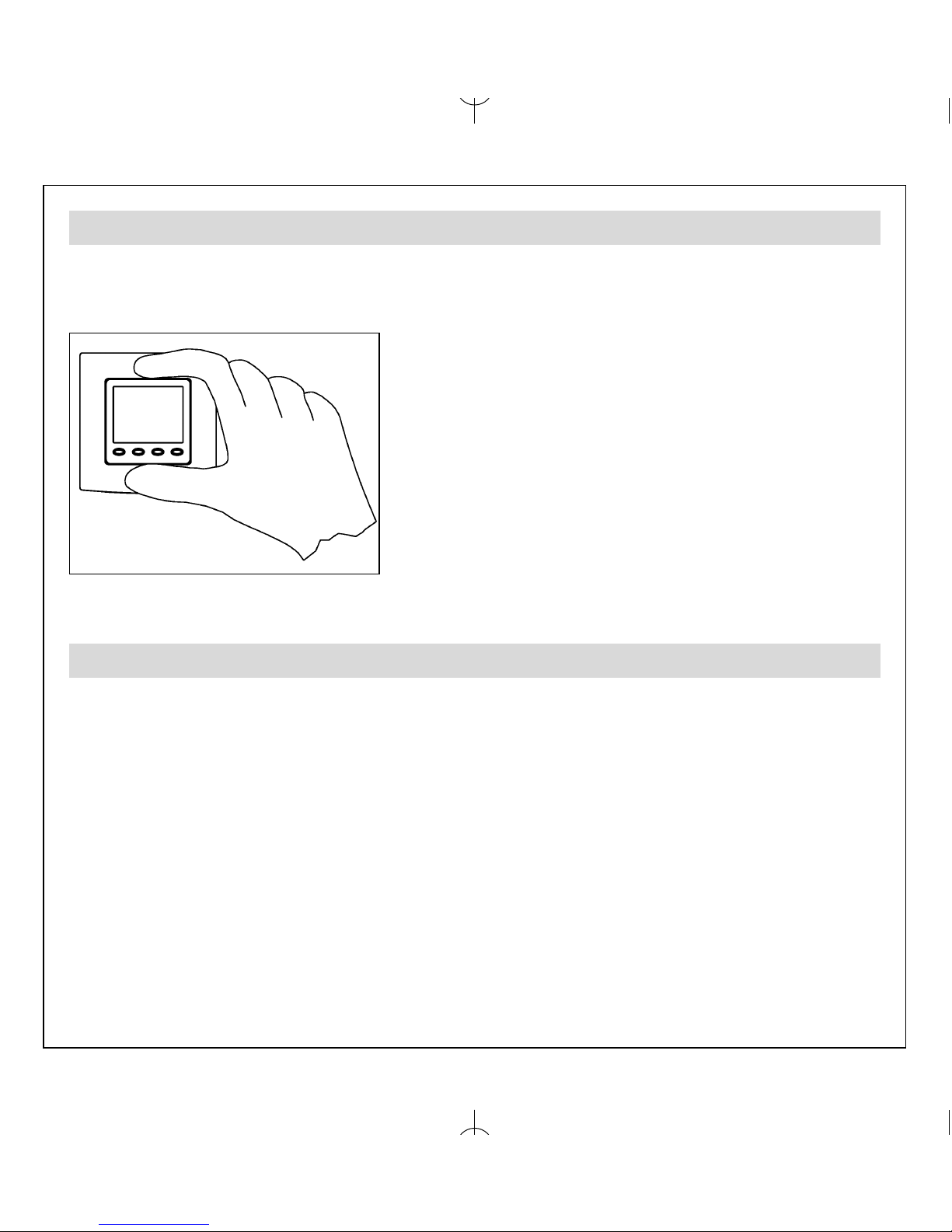
werden. Zum Öffnen des Gerätes oben und unten am
Gehäusedeckel greifen und ziehen, wie in nebenstehender
Zeichnung dargestellt.
7. Montage/Anschluss
Bei der Erstinbetriebnahme werden automatisch die Expertenmenüpunkte 6.1 Sprache, 6.2
Reglertyp, 6.3 externer Sensor, 6.4 Wichtung (nur wenn ein externer Sensor ausgewählt wurde)
sowie die Anmeldefunktion (5.7.7) aufgerufen, um so die Erstkonfiguration des Reglers vorzunehmen.
8. Erstinbetriebnahme

17
9. Anschluss- und Maßzeichnung

18
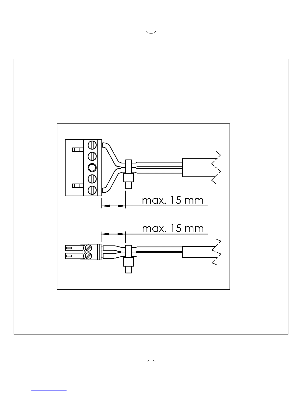
Wichtiger Hinweis!
Die Einzeladern der Netzspannungsversorgung und der Sensorleitungen sind durch Setzen je eines
Kabelbinders gegen Verlagerung zu sichern. Hierbei ist auf einen möglichst kurzen Abstand, maximal jedoch 15 mm, zwischen Kabelbinder und Netzanschluss bzw. Sensorklemmen zu achten.
Klemme Netzanschluss
Klemme Sensor SELV

19
10. Technische Daten
Betriebsspannung: 230V~, 50Hz
Fühler: NTC – intern
NTC – extern 2 kΩ, 3 kΩ, 10 kΩ, 12 kΩ, 15 kΩ,
33 kΩ, 47 kΩ anschließbar
Einstellbereiche: 5 … 30°C Komfort
- 1K … - 6K ECO Heizen
+1K … +6K ECO Kühlen
Sensortoleranz: ca. +/- 1K
Anzeige: beleuchtetes, grafisches Display
Elektrischer Anschluss: Schraub-Steckklemmen
netzspannungsseitig 0,75 – 2,5 mm
2
niederspannungsseitig 0,08 – 1,5 mm
2
Sendefrequenz: 868,3 MHz
Leistungsaufnahme: max. 0,4 W, ca. 1,6 VA
Schutzart: IP 30
Schutzklasse: II, nach entsprechender Montage
Gangreserve: ca. 3 Tage
zul. Luftfeuchte: max. 95%, nicht kondensierend
Lagertemperatur: – 20 … + 70°C
Umgebungstemperatur: 0 … 40°C
Farbe Gehäuse: reinweiß, perlweiß oder verkehrsweiß
Material Gehäuse: PC, PMMA, ABS
Montage / Befestigung: in Unterputzdose, in nahezu alle
Energieeffizienzklasse: I = 1% (EU 811/2013)
Schalterprogramme adaptierbar
Hiermit erklärt OHLE GmbH & Co. KG,
dass der Funkanlagentyp
„Thermostat-Sender mit Masterfunktion,
Unterputz“ der Richtlinie 2014/53/EU entspricht.
Der vollständige Text
der EU-Konformitätserklärung ist unter
der folgenden Internetadresse verfügbar:
www.elektroheizung.com

20
11.Sensorkennlinien
Alle Angaben erfolgen in k
Ein Sensorfehler wird im Display mit einer Fehlermeldung angezeigt.
2k 3k 10k 12k 15k 33k 47k
0°C 5,64 9,79 27,42 37,94 40,80 117,36 155,48
5°C 4,53 7,62 22,14 29,64 33,13 89,45 120,70
10°C 3,66 5,97 18,00 23,36 27,04 68,84 94,38
15°C 2,97 4,71 14,72 18,57 22,12 53,47 74,31
20°C 2,43 3,75 12,10 14,87 18,15 41,86 58,91
25°C 2,00 3,00 10,00 12,00 15,00 33,00 47,00
30°C 1,65 2,42 8,31 9,75 12,39 26,21 37,73
35°C 1,38 1,96 6,94 7,96 10,33 20,88 30,47
40°C 1,15 1,60 5,82 6,57 8,60 16,74 24,75
45°C 0,97 1,31 4,90 5,44 7,19 13,50 20,21
13. Gewährleistung
Die von uns genannten technischen Daten wurden unter Laborbedingungen nach allgemein gültigen
Prüfvorschriften, insbesondere DIN-Vorschriften, ermittelt. Nur insoweit werden Eigenschaften zugesichert. Die
Prüfung der Eignung für den vom Auftraggeber vorgesehenen Verwendungszweck bzw. den Einsatz unter
Gebrauchsbedingungen obliegt dem Auftraggeber; hierfür übernehmen wir keine Gewährleistung. Änderungen
vorbehalten.
12. Zubehör
PFC47 Strahlungsfühler als Pendelfühler
STF-2 Strahlungsfühler im Raumfühlergehäuse
BTF2-C47-0000 Raumfühler
LF-22 Luftfühler
HF-2 Hülsenfühler
THF Schutzhülse für Fußbodenfühler bei Estrichmontage
OHLE GmbH & Co. KG - An der Alster 1 - D-20099 Hamburg

21

22
11. Safety information . . . . . . . . . . . . . . . . . . . . . . . . . . . . . . . . . . . . . . . . . . . . 023
12. Application . . . . . . . . . . . . . . . . . . . . . . . . . . . . . . . . . . . . . . . . . . . . . . . . . . 023
13. Operating instructions . . . . . . . . . . . . . . . . . . . . . . . . . . . . . . . . . . . . . . . . . 023
14. Control operation . . . . . . . . . . . . . . . . . . . . . . . . . . . . . . . . . . . . . . . . . . . . . 024
14.1 Temporary set temperature setting . . . . . . . . . . . . . . . . . . . . . . . . . . . . . . . 024
14.2 Selection of the operating mode / antifreezing function . . . . . . . . . . . . . . . 025
15. Main menu . . . . . . . . . . . . . . . . . . . . . . . . . . . . . . . . . . . . . . . . . . . . . . . . . .026
15.1 Submenu “Party” . . . . . . . . . . . . . . . . . . . . . . . . . . . . . . . . . . . . . . . . . . . . . 028
15.2 Submenu “Holiday” . . . . . . . . . . . . . . . . . . . . . . . . . . . . . . . . . . . . . . . . . . . 028
15.3 Setting of the time / the date . . . . . . . . . . . . . . . . . . . . . . . . . . . . . . . . . . . . 029
15.4 Entry of the set temperatures . . . . . . . . . . . . . . . . . . . . . . . . . . . . . . . . . . . 029
15.5 Entry of the weekday programs . . . . . . . . . . . . . . . . . . . . . . . . . . . . . . . . . . 30
15.6 Information . . . . . . . . . . . . . . . . . . . . . . . . . . . . . . . . . . . . . . . . . . . . . . . . . . . 32
15.7 Settings . . . . . . . . . . . . . . . . . . . . . . . . . . . . . . . . . . . . . . . . . . . . . . . . . . . . . 32
16. Experts menu . . . . . . . . . . . . . . . . . . . . . . . . . . . . . . . . . . . . . . . . . . . . . . . . . 35
17. Mounting / connection . . . . . . . . . . . . . . . . . . . . . . . . . . . . . . . . . . . . . . . . . . 36
18. First start-up and commissioning . . . . . . . . . . . . . . . . . . . . . . . . . . . . . . . . . 36
19. Wiring diagram and dimensioned drawing . . . . . . . . . . . . . . . . . . . . . . . . . . 37
10. Technical data . . . . . . . . . . . . . . . . . . . . . . . . . . . . . . . . . . . . . . . . . . . . . . . . 39
11. Sensor characteristics . . . . . . . . . . . . . . . . . . . . . . . . . . . . . . . . . . . . . . . . . . 40
12. Accessories . . . . . . . . . . . . . . . . . . . . . . . . . . . . . . . . . . . . . . . . . . . . . . . . . . 40
13. Warranty . . . . . . . . . . . . . . . . . . . . . . . . . . . . . . . . . . . . . . . . . . . . . . . . . . . . 40
Table of contents, overview
GB

23
This flush-mounted radio temperature sensor (transmitter) with time-controlled energy economizing
function has been specially devised for the acquisition of temperatures in living spaces, offices and
hotel rooms. It has been designed for use in association with one or several radio temperature controllers (receivers). The overall system that usually consists of both a radio temperature sensor and
a radio temperature controller forms one unit and serves for the wireless temperature control of individual rooms. It is chiefly used in the building reconstruction sphere or wherever heating systems are
to be extended and where the avoidance of expensive cutting up and/or plaster works for the laying
of electric cables is of importance. The same applies also with regard to modern office complexes
where flexibility with regard to the interior design is in the fore. Regarding other applications not to be
foreseen by the manufacturer of this device, the safety standards concerning these applications need
to be followed and adhered to. Regarding the aptitude of the device for any such application, please
refer to section 13. herein (Warranty).
2. Application
The device is equipped with 4 touch keys, all of which have been marked by impressed ovals . The
functions allocated to them may vary in dependence on the operation requirements. The related
function is being indicated on the display that exists above the corresponding keys. A special protective function helps prevent an inadvertent activation of the touch keys . This function is activated
20 seconds after any of the touch keys has last been activated. Actuating any of the touch keys deactivates this function again for 2 seconds (see advice indicated on the display). The heating or cooling
mode menu and setting functions are only available if the corresponding controller type has been set
beforehand.
3. Operating instructions
Expert electricians only may open this device in due compliance with the wiring diagram shown in the
housing cover / on the housing / represented in the corresponding operating instructions. All expert
electricians charged with the execution of such works must comply with the relevant safety regulations currently operative and in force.
Caution: The operation of the flush-mounted radio temperature sensor in the vicinity of other devices that do not comply with the EMC directives may affect its functions. The company charged with
the installation of the device must, after the completion of the installation works, instruct the user of
the control system into its functions and in how to operate it correctly. These operating instructions
must be kept at a place that can be accessed freely by the operating and/or servicing personnel in
charge.
1. Safety information
0
0

24
If no key has been activated within a period of approx. 5 seconds, the system returns to normal control mode again. The changed temperature value is being taken over and imported. The adjusted set
temperature continues to be effective until the moment the operating mode is changed, no matter if
changing manually or automatically. The same applies if the holiday or party function has been started
or cancelled or the experts menu been called up.
4. Control operation
Temporary set temperature setting see 4.1
Selection of the operating mode see 4.2
Main menu see 5.
Temporary set temperature setting see 4.1
4.1 Temporary set temperature setting
Set temperature – 0.5K
Import of the values / return to normal control mode
Set temperature + 0.5K

25
4.2 Selection of the operating mode / antifreezing function
Actuating the touch key Mode allows to change the operating mode
in the order shown below:
– Automatic mode (control in dependence on the adjusting weekday program see 5.4 / 5.5)
– Comfort mode (permanent control targeted at maintaining the adjusted comfort temperature
see 5.4)
– ECO mode (permanent control targeted at maintaining the adjusted ECO temperature
see 5.4)
– Standby mode (antifreezing mode)
In “standby” mode, the controller activates the antifreezing function each time the temperature value
measured by the internal or the activated external sensor falls below a level of approx. 5°C. This antifreezing function helps prevent rooms from cooling down thoroughly, thus protecting against the
occurrence of frost damage.

26
5. Main menu
Actuating the key terminates the main menu.
Submenu
Party
씮 see 5.1
Submenu
Holiday
씮 see 5.2
Submenu
Time
씮 see 5.3
Submenu
Date
씮 see 5.3
Submenu
Temperature
씮 see 5.4
쑼쑼쑼쑼쑼
쑼쑼 쑼쑼 쑼쑼 쑼쑼 쑼

27
5. Main menu
쑼
Submenu
Weekday program
“heating”
씮 see 5.5
Submenu
Weekday program
“Cooling”
씮 see 5.5
Information
씮 see 5.6
Submenu
Settings
씮 see 5.7
Calling of the
experts menu
씮 see 6.
If the controller has been configured for heating/cooling control applications (see 6.2), separate
weekday programs for both heating and cooling mode control operations can be created. If it has
been configured for either heating or cooling control applications, only the respective setting
function is available.
쑼쑼쑼쑼쑼쑼쑼
쑼쑼쑼쑼

28
5.1 Submenu “Party”
Party duration – 15 minutes
Termination of entries / returning to the main menu
Mains menu 씮 see 5.
Month in which holidays begin - 1
Termination of entries / returning to the main menu
Changing over to the day on which holidays begin
Month in which holidays begin +1
Actuating the touch key starts the party function. Once the pre-adjusted time has been
attained, the system switches automatically back to the previous operating mode. Actuating the
touch key cancels the party function at any time.
Party duration + 15 minutes
5.2 Submenu “Holiday”
The settings “Day on which holidays begin”, “Month in which holidays end” and “Day on which
holidays end” are made in the same manner as explained above with regard to the setting “Month
in which holidays begin”.
Already existing holiday data can be cancelled by calling up the holiday submenu again. Actuating
the key cancels the existing entries.
The settings “Day on which holidays begin”, “Month in which holidays end” and “Day on which
holidays end” are made in the same manner as explained above with regard to the setting “Month
in which holidays begin”. Following this, the difference between the holiday temperature and the
comfort temperature set value needs to be entered. Values within a range from +/-1K to +/-6K can
be entered or the heating/cooling operations deactivated during the holiday period. However, the
antifreezing function remains active (factory settings: heating -3K, cooling +3K).
Actuating the key imports the selected values. Actuating the key after calling up the
holiday submenu cancels all already existing holiday data.

29
5.3 Setting of the time / the date
For the entry of the minutes proceed in the same manner as explained above with regard to the
entry of the hours. Actuating the key after a change of the minutes imports the changed
values and brings the operator back to the main menu. At the same time, the seconds are
being reset to “0”. For the setting of the date (year, month and day) proceed in the same manner.
Hour – 1
Termination of entries / returning to the main menu
Changing to the minute entry display
Hour + 1
Comfort temperature – 0.5K
Termination of entries / returning to the main menu
Import of the selected value and changeover to the
ECO temperature entry display
Comfort temperature + 0,5K
5.4 Entry of the set temperatures
Factory setting: 20°C
During all comfort times the control operations will be performed to meet this value.

30
For the entry of the ECO temperatures, proceed in the same manner as explained above with
regard to the entry of the comfort temperature. The ECO temperature data entered define as
values that differ by certain margin in relation to the comfort temperature. Regarding operation in
heating mode, a temperature decrease by a value within the range 1K … 6K can be set or
operation in antifreezing mode selected.
Factory setting: -3K
Regarding operation in cooling mode, a temperature increase by a value within the range
1K … 6K can be set.
Factory setting: +3K
The resulting set temperature is being displayed in the second line.
ECO temperature difference -1K
Termination of entries / returning to the main menu
Import of the selected value
ECO temperature difference +1K
Weekday backward
Termination of entries / returning to the main menu
Changing to the comfort and ECO time entry display
Weekday onward
5.5 Entry of the weekday programs
Selection of the weekday

31
5.5 Entry of the weekday programs
Selection of the comfort ( 쎱 ) and ECO ( _ ) times
“Heating” comfort times, factory settings:
Monday to Friday: 05:00 … 9:00 a.m. / 16:00 … 22:00 p.m.
Saturday and Sunday: 06:00 a.m. … 22:00 p.m.
“Cooling” comfort times, factory settings:
Monday to Friday: 00:00 … 9:00 a.m. / 16:00 … 00:00 p.m.
Saturday and Sunday: 00:00 … 24:00
Position + / – 15 minutes
Termination of entries. If no changes have
been made, the system returns to the display for
the selection of the weekday. Otherwise, it changes
over to the entry confirmation display.
Shifting between comfort or ECO time period
5.5 Entry of the weekday programs
Confirmation of entries
Storing of the entries, change to the menu enabling the
copying of entries with respect to other weekdays
Termination of entries / returning to the weekday
selection display

32
5.5 Entry of the weekday programs
Import of the entries made with regard to other weekdays
Selection forward / backward
No import of the entry,
returning to the weekday selection display
Import of entries with respect to the
selected weekday(s).
5.6 Information
Indication of the QR code:
The internet address coded in the QR code allows to access further
information on this controller so long as this function is available.
5.7 Settings
Selection downward / upward
Termination of entries /
returning to the main menu
Activation or deactivation of the
selected function

33
5.7 Settings
The following functions are available:
5.7.1. Keylock
The keylock is activated about 2 minutes after one of the touch keys has been actuated and the key
symbol appears on the display to indicate this. Touching any of the touch keys for approx.10 seconds
activates them again.
Factory setting: OFF
5.7.2. Automatic change to daylight saving and standard time
The harmonised daylight saving time in the European Union takes effect as of the last Sunday in
March, i.e. as of 2.00 o’clock a.m. CET and lasts until to 3.00 o’clock a.m. on the last Sunday in
October (CEST) each year (Directive 2000/84/EC of the European Council and Parliament). This
room temperature controller changes the time all automatically at these dates. The automatic change
to daylight saving and standard time can also be deactivated to enable the changing of the time at
other dates or to meet the time conditions in other regions.
Factory setting: ON
5.7.3. Valve and pump protection function
The valve and pump protection function helps prevent the valve seat and/or the pump from corroding
up during longer stop times. Whenever warm-water heating systems are to be controlled, it is recommended to activate the valve protection function. Once the valve and pump protection has been activated, the controller actuates the related valve or triggers, at each time, a circulating pump every
Monday at 11.00 o’clock a.m. for a 5-minute time.
Factory setting: OFF
5.7.4. Learn function
The learn function serves for the autonomous attaining of the “heating” comfort temperature value at
a preset time. The antedated point at which the system switches from ECO over to comfort temperature sets itself all autonomously. Depending on the calorific output and the prevailing outside temperature, the heating time will vary. The learning function is available only if operating in heating mode.
Factory setting: OFF
5.7.5. Backlighting of the display
The length of time during which the display backlight is on, can be selected as follows:
1. Backlight during operation plus 10 seconds after the last actuation of any of the touch keys;
2. In addition to above 1.: Backlight during the “heating” comfort times and during operation in party
mode;
3. In addition to above 1.: Backlight during the “heating” and “cooling” comfort times and during
operation in party mode;
4. In addition to above 1.: Backlight during the “cooling” comfort times and during operation in
party mode;
5. Permanent backlight.
Factory setting: 10 seconds

34
5.7.6 Display indications
The following indications can be selected:
1. Time
2. Temperature
3. Time & temperature (alternating)
Factory setting: Time & temperature (alternating)
5.7.7 Assigning and cancelling of learned radio temperature sensors
1. The assigning function allows to train a radio temperature sensor (transmitter) so that it can com-
municate with the related radio temperature controller (receiver). This requires switching the radio
temperature controller (receiver) over to operation in learning mode. Actuating the key while
operating in this mode starts the transmission of a learn identifier that continues for 10 seconds. The
radio symbol on the display flashes to indicate this transmission. For more information on the receiver’s response to the reception of this learn identifier, please consult the operating instructions supplied with the related receiver.
2. The cancelling function allows to unlearn a radio temperature sensor (transmitter) from the corre-
sponding radio temperature controller (receiver). Actuating the key while operating in this mode
starts the transmission of an unlearn identifier that continues for 10 seconds. The radio symbol on
the display flashes to indicate this transmission. To enable the cancelling of an assigned radio temperature sensor, the receiver too must be switched over to operation in cancelling mode. For more
information on how to start the cancelling mode at the receiver, please consult the operating instructions supplied with the related device.
5.7.8 Factory settings
This function allows to reactivate the following factory settings:
– The weekday programs
– The comfort temperature set value
– The ECO temperature (difference) values (“heating/cooling”)
– Possibly entered holiday dates, including the holiday temperature set value
– Weekday program based automatic mode
– The display indications
– The duration of the backlight time
– The “learned” temperature gradient (see 5.7.4., “Learn function”)

35
Factory setting: Importance of the internal sensor set to 90%
Increase of the importance of the internal sensor +10%
Termination of entries
Import of the selected values / returning to the experts menu
Increase of the importance of the external sensor +10%
6. Experts menu
Depressing the right touch key and keeping it depressed for 10 seconds after accessing the “settings”
submenu (see 5.) from the main menu enables to call the experts menu.
Caution! This menu enables to make control settings that may only be performed by a qualified heating specialist or an expert electrician. The settings made while operating in this mode cannot be reset
via the reset function and have to be made knowingly, therefore.
The following settings are available:
6.1 Language
The operator can select between the following languages: Czech, Dutch, English, French, German,
Polish and Russian.
6.2 Selection of controller types
The following controller types can be selected: “heating”, “heating/cooling” or “cooling”.
6.3 External sensor
This device provides the option to connect external temperature sensors (type NTC) showing ohmic
resistances of 2 k액,3 k액, 10 k액, 12 k액, 15 k액, 33 k액, or 47 k액 at a temperature of 25°C.
The temperature sensor needed for use is to be selected here.
(Factory setting: No external sensor connected.)
6.4 Importance relation between internal and external sensor
(available only after the selection of an external sensor)
6.5 Measuring correction
The measured temperature value can, in dependence on the related configuration, individually be
adjusted with regard to the internal and external temperature sensor within a range from -5K to +5K
at 0.1K steps. At the same time, the uncorrected value measured by the related sensor is being indicated on the display (factory setting 0.0).
36
The controller is determined for installation in an UP box and may not be exposed directly to any heat
or cold sources. Furthermore, care must be taken to ensure that the device is not exposed to the influence of foreign heat or cold sources that warm or cool the device at its back (through air flows in cavity
walls or the temperatures radiated by ascending pipelines, f. ex.). The controller is to be mounted on
the wallpaper or wall covering, respectively.
The device equipped with the 50x50mm housing cover can
be integrated into almost all currently available flush switch
installation frame systems when using DIN 49075 compliant intermediate frames The device equipped with the
55x55mm housing is, likewise, suited for use with different
frame systems. If using multiple frames, the controller
needs always to be mounted in the lowest position.
Caution: Prior to performing any installation works
always make sure to disconnect the mains voltage at
all poles! The electrical connection is to be realised as
shown in the connection diagram in section 9. herein. The
pluggable screw terminals can comfortably be pre-wired
for this purpose and connected to the controller while
installing it into the under plaster box. The opening of the device is realised as described in the drawing opposite by holding the housing cover at the top and bottom and pulling it open.
7. Mounting / connection
When starting the device up for the first time, the experts menu items 6.1, “Language”, 6.2, “Controller
type”, 6.3, “External sensor” and 6.4, “Importance relation between internal and external sensor”,
including 5.7.7, “Assigning and de-assigning function”, are being called up all automatically to configure the controller for the first time as needed.
8. First start-up and commissioning

37
9. Wiring diagram and dimensioned drawing
38
Important advice!
The single power supply wires, including those of the sensors should be protected against shifting by
fixing one cable tie each as shown here below. In doing so, care must be taken to ensure that the
distance between the cable tie and the mains voltage or sensor terminals is as short as possible
(maximum 15 mm).
Terminal for mains voltage connection
Terminal for sensor connection (SELV)

39
10. Technical data
Operating voltage: 230V~, 50Hz
Sensors: NTC, internal type
NTC, external type (sensors with ohmic resistances
of 2 kΩ, 3 kΩ, 10 kΩ, 12 kΩ, 15 kΩ, 33 kΩ, 47 kΩ can be connected)
Setting ranges: 5 … 30°C comfort mode
- 1K … - 6K ECO heating
+1K … +6K ECO cooling
Sensor tolerance: approx. +/- 1K
Display: graphic display, backlit
Electrical connection: pluggable screw terminals;
0.75 – 2.5 mm
2
(power supply side);
0.08 – 1.5 mm
2
(low voltage side)
Transmit frequency: 868,3 MHz
Power consumption: max. 0.4 W (approx. 1.6VA)
Degree of protection: IP 30
Protection class: II (after conforming installation)
Power reserve: approx. 3 days
Admissible air moisture: max. 95% RH, non condensing
Storage temperature: – 20 … + 70°C
Ambient temperature: 0 … 40°C
Housing colour: pure white, pearly white or traffic white
Housing material: made of PC,
PMMA or ABS
Installation / mounting: in an UP box; suited for integration into all currently available flush
Energy efficiency class I = 1% (EU 811/2013)
mounted switch frame installation systems
Hereby,
OHLE GmbH & Co. KG
declares that the radio equipment type
“Thermostat transmitter with master function,
flush-mounted” is in compliance with Directive
2014/53/EU. The full text of the EU declaration
of conformity is available at the
following internet address:
www.elektroheizung.com

40
13. Warranty
The technical data specified herein have been determined under laboratory conditions and in compliance with
generally approved test regulations, in particular DIN standards. Technical characteristics can only be warranted
to this extent. The testing with regard to the qualification and suitability for the client’s intended application or the
use under service conditions shall be the client’s own duty. We refuse to grant any warranty with regard thereto.
Subject to change without notice.
12. Accessories
PFC47 Pendulum type radiation sensor
STF-2 Wall mounting type radiation sensor
BTF2-C47-0000 Ambient temperature sensor
LF-22 Air sensor
HF-2 Sleeve sensor
THF Immersion sleeve for sleeve sensor HF
OHLE GmbH & Co. KG - Mittelweg 10 - D-20148 Hamburg
11.Sensor characteristics
All indications in the table below in k
Corresponding messages are being displayed once a sensor error occurred.
2k 3k 10k 12k 15k 33k 47k
0°C 5.64 9.79 27.42 37.94 40.80 117.36 155.48
5°C 4.53 7.62 22.14 29.64 33.13 89.45 120.70
10°C 3.66 5.97 18.00 23.36 27.04 68.84 94.38
15°C 2.97 4.71 14.72 18.57 22.12 53.47 74.31
20°C 2.43 3.75 12.10 14.87 18.15 41.86 58.91
25°C 2.00 3.00 10.00 12.00 15.00 33.00 47.00
30°C 1.65 2.42 8.31 9.75 12.39 26.21 37.73
35°C 1.38 1.96 6.94 7.96 10.33 20.88 30.47
40°C 1.15 1.60 5.82 6.57 8.60 16.74 24.75
45°C 0.97 1.31 4.90 5.44 7.19 13.50 20.21
 Loading...