

Ohkura VM7000A Operation Manual

VM7000A
Paperless Recorder
Operation Manual
WXPVM70mnA0001E
October, 2009(Rev.2)
All Rights Reserved, Copyright © 2009, Ohkura Electric Co.,Ltd.

To use this equipment safely
Thank you for purchasing our VM7000A Paperless Recorder.
・Please installs it, operates it and prepares it, after this manual is often read, and it understands enough.
There is danger where the accident and the trouble occur when handling is mistaken.
This specification of Recorder is subject to change without prior notice for product improvement.
・
・
It is prohibited to remodeling this Paperless Recorder without our permission.
It doesn't assume the responsibility about the accident caused by having remodeled it without our permission.
・Please keep this manual if you actually use the Recorder.
After reading this manual, keep it carefully by the instrument.
・
・
Please consider this manual to be sure to extend to the final user.
Manufacturer:Ohkura Electric
Format:It records in the main body plaque.
Manufacture date:It records in the main body plaque.
Manufacture country:Japan
Note:Windows are registered trademarks of Microsoft Corporation.
Co.,Ltd.
[Note]
・It is prohibited to copy this manual without our permission.
・
This instruction manual is subject to change without prior notice.
- i -
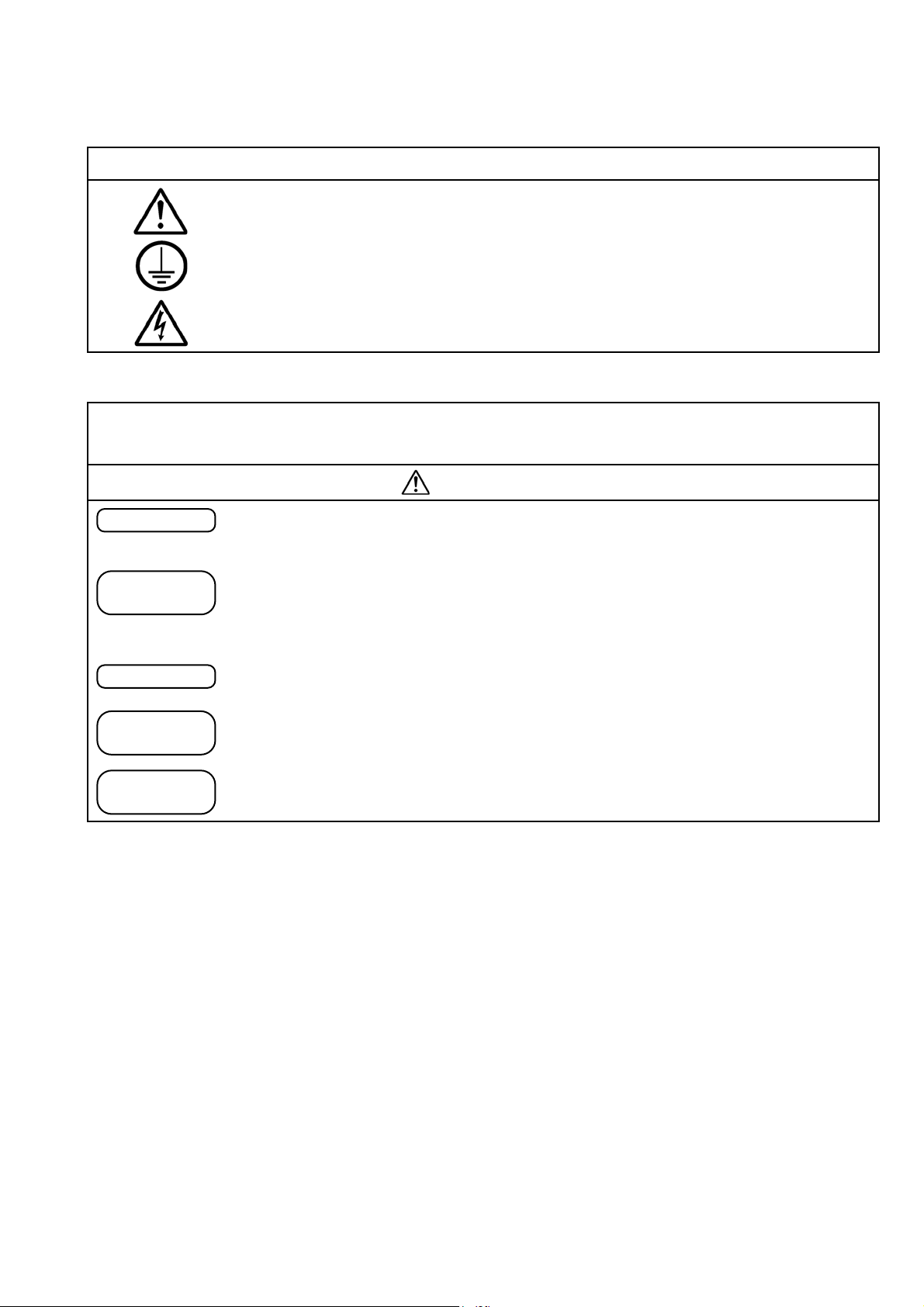
The symbols below are used on this instrument for the cautioning information.
Symbols used on the instrument
This shows “Caution for handling”.
This symbol is used on the parts need to reference the instruction manual for saving
human body and the instrument.
This shows “Protective grounding”.
Be sure to provide protective grounding prior to operate this instrument.
This shows “Risk of electric shock”.
This symbol is used on the parts, which has a risk of electric shock.
Be sure to observe the following warnings/cautions and those provided in the
text in order to secure safety in handling the instrument.
WARNING
General
Protective
Grounding
Power Source
Working
Environment
In order to prevent electric shock; be to disconnect this instrument from the main power
source when wiring it.
(1) In order to prevent an electric shock; be sure to provide protective grounding prior
to turning on this instrument.
(2)
Do not cut a protective grounding conductor or disconnect protective grounding.
Make sure that the supply voltage for this instrument conforms to the voltage of the
supply source.
Do not operate this instrument in the environment where it is exposed to a combustible
/ explosive / corrosive gas or water / steam.
Input and
Output Wiring
Provide input and output wring after turning off the power.
- ii -
Input and
Output Wiring
CAUTION
Do not use empty terminals for other purposes such as relaying, etc.
Reverse-insertion
attention
Please confirm the direction to the insertion of SD card.
When forcibly inserting it in a wrong direction, SD card and the terminal on the main
body side might be destroyed.
Please mote that the damage of the equipment by the reverse-insertion becomes off the
subject of amends.
Inside of
trument
Ins
Do not replace the main unit or printed circuit boards. When this is neglected, we
cannot guarantee functioning of the instrument. Contact our dealer where you
purchased the instrument, or our sales representative.
Instruction
Manual
(1) Deliver this instruction manual to an end user.
(2)
Prior to handling this instrument, be sure to read this manual.
(3)
If you have any questions on this manual or find any errors or omissions in this
manual, contact our sales representative.
(4) After reading this manual, keep it carefully by the instrument.
(5) When the manual is lost or stained, contact our sales representative.
(6) It is prohibited to copy or reproduce this manual without our permission.
Installation
(1) When installing this instrument, put on a protective gear such as safety shoes,
helmet, etc. for your safety.
(2) Do not put your foot on the installed instrument or get on it, because it is
dangerous.
Maintenance
Only our serviceman or persons authorized by OHKURA are allowed to remove and
take the inner module, the main unit and printed circuit boards apart.
Cleaning
Revisions
Free Dial
(1) Use dry cloth to clean the surface of this instrument.
(2) Do not use any organic solvent.
(3) Cleaning the instrument after turning off the power.
This instruction manual is subject to change without prior notice.
(The Inquiry about the industrial instrument)
About the handling of the product and maintenance:
[ Note]
0120-17-0096
- iii -

<CONTENTS>
1. INTRODUCTION -------------------------------------------------------- 1-1
1.1 Paperless Recorder ------------------------------------------------------------------------ 1-1
1.2 Accessory check ---------------------------------------------------------------------------- 1-1
1.3 When temporarily keeping it ------------------------------------------------------------ 1-1
1.4 Confirmation of form and specification ----------------------------------------------- 1-2
1.5 Handling SD card -------------------------------------------------------------------------- 1-3
2. NAMES AND FUNCTIONS OF PARTS ---------------------------- 2-1
2.1 Names and functions of parts ----------------------------------------------------------- 2-1-
2.2 Set of O-ring for waterproof ------------------------------------------------------------ 2-3
3. INSTALLATION --------------------------------------------------------- 3-1
3.1 Installation place -------------------------------------------------------------------------- 3-1
3.2 Installation on panel ---------------------------------------------------------------------- 3-1
4. WIRING -------------------------------------------------------------------- 4-1
4.1 Terminal stand array and LAN connector ------------------------------------------- 4-1
4.2 Wiring for power supply ----------------------------------------------------------------- 4-2
4.3 Wiring for analog input ------------------------------------------------------------------ 4-3
4.4 Wiring for COM ALM
4.5 Wiring for LAN cable
4.6 Wiring for DI/DO (Option) -------------------------------------------------------------- 4-5
4.7 Wiring for relay output (Option) ------------------------------------------------------- 4-6
-------------------------------------------------------------------- 4-4
--------------------------------------------------------------------- 4-4
5. OPERATION -------------------------------------------------------------- 5-1
5.1 Before operating --------------------------------------------------------------------------- 5-1
5.2 Start and stop of record ------------------------------------------------------------------ 5-1
6. DISPLAY FUNCTION -------------------------------------------------- 6-1
6.1 Basic composition of data display screen --------------------------------------------- 6-1
6.2 Real time trend display of measured data -------------------------------------------- 6-4
6.3 Display of measured data in bar graphs ---------------------------------------------- 6-4
6.4 Digital display of measured data ------------------------------------------------------- 6-5
6.5 Historical trend display ------------------------------------------------------------------ 6-6
6.6 Event history / communication history display ------------------------------------- 6-8
- iv - - v -

7. SETTINF AND CHECKING PARAMETERS -------------------- 7-1
7.1 Operational mode ------------------------------------------------------------------------ 7-1
7.2 Setting and checking --------------------------------------------------------------------- 7-2
7.3 Outline of parameter setting procedure --------------------------------------------- 7-3
7.4 Basic operation of setting screens ----------------------------------------------------- 7-4
7.5 Setting the input spec -------------------------------------------------------------------- 7-7
7.6 Input CH ----------------------------------------------------------------------------------- 7-9
7.7 Calc. CH ------------------------------------------------------------------------------------ 7-11
7.8 Display -------------------------------------------------------------------------------------- 7-13
7.9 Record -------------------------------------------------------------------------------------- 7-14
7.10
Others --------------------------------------------------------------------------------------- 7-15
8. SETTING AND CHECKING SYSTEMS --------------------------- 8-1
8.1 Outline of system setting procedure -------------------------------------------------- 8-1
8.2 SD / Param --------------------------------------------------------------------------------- 8-2
8.3 Comm. -------------------------------------------------------------------------------------- 8-3
8.4 Device / Other ----------------------------------------------------------------------------- 8-5
8.5 Engineering -------------------------------------------------------------------------------- 8-6
9. SPECIFICATION ------------------------------------------------------- 9-1
9.1 Basic specification ------------------------------------------------------------------------ 9-1
9.2 Measurement range ---------------------------------------------------------------------- 9-2
9.3 Display part -------------------------------------------------------------------------------- 9-3
9.4 Operation Button ------------------------------------------------------------------------- 9-3
9.5 Record function --------------------------------------------------------------------------- 9-4
9.6 Alarm function ---------------------------------------------------------------------------- 9-5
9.7 Ethernet (10BASE-T) -------------------------------------------------------------------- 9-5
9.8 Power supply part ------------------------------------------------------------------------ 9-6
9.9 Structure ----------------------------------------------------------------------------------- 9-6
9.10 Normal operating condition ------------------------------------------------------------- 9-6
9.11 Others ---------------------------------------------------------------------------------------- 9-6
9.12 Compatible specification ----------------------------------------------------------------- 9-7
9.13 Transportation and storage conditions ------------------------------------------------ 9-7
9.14 Optional function (Option) --------------------------------------------------------------- 9-7
9.15 Support software --------------------------------------------------------------------------- 9-8
9.16 Externals size -------------------------------------------------------------------------------- 9-9
1. INTRODUCTION
1.1 Paperless Recorder
① This recorder displays measured data in real time on the liquid crystal display. It is a paperless
type that is also capable of saving the measured data to a SD memory card (hereinafter referred to
as SD card). It can operate easily with the liquid crystal with the touch panel.
② It can set up to 12 channels for the input types such as thermocouple, resistance bulb, and DC
voltage (or current).
③ It allows the measured data saved to the SD card to be displayed on the display unit.
Use of the support software attached to the recorder allows the saved data to be displayed on a
personal computer.
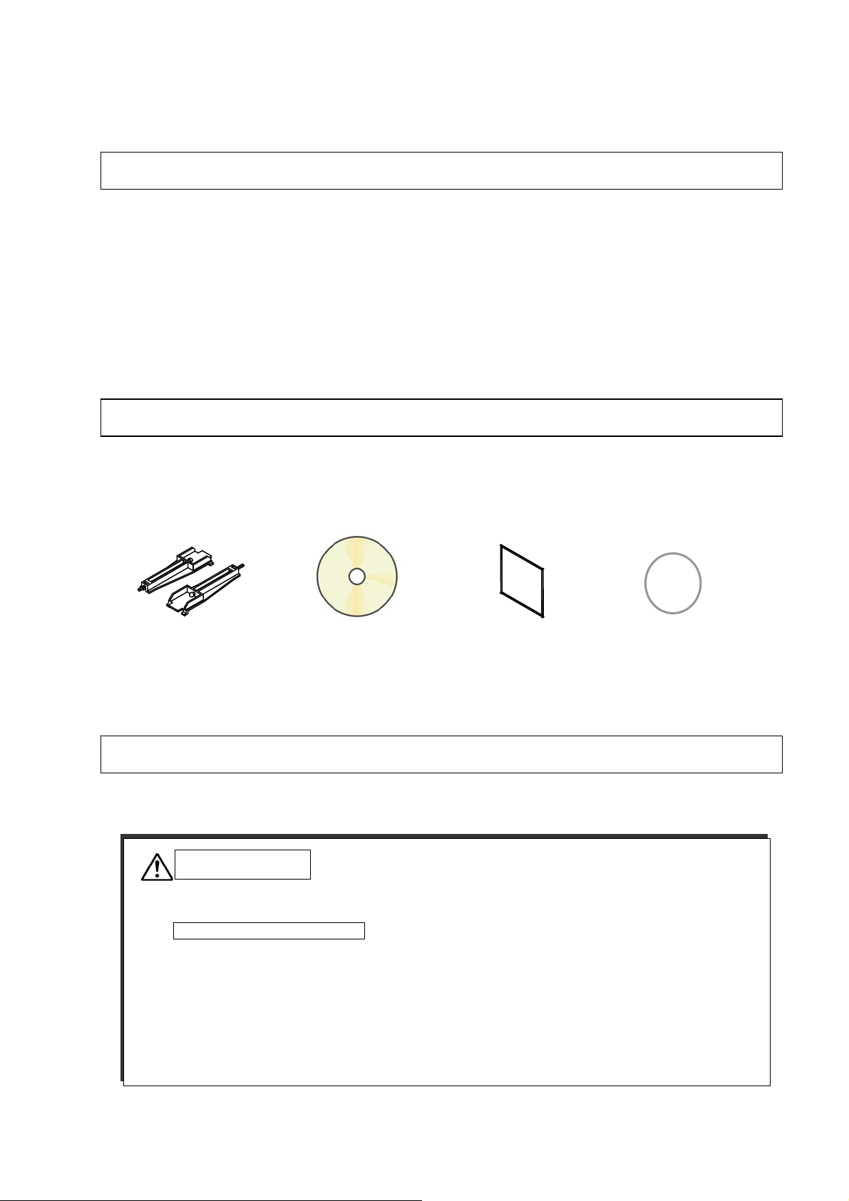
1.2 Accessory check
Upon receiving the recorder unit, check the appearance for damage, and if the correct quantity of the
accessories are supplied. Please contact the shop that purchases it or our salesman when there is a
part not suitable by any chance.
① Panel-mounting
bracket
② CD-ROM
(Operation manual,
Support software)
l packing
④ O-ring for w
aterproof ③ Pane
1.3 When temporarily keeping it
Please keep this recorder in the following environment. Please keep it in the following environment
when it is built in the device.
CAUTION
Externals, the function, and the longevity etc. of the product might be ruined when
keeping it in poor surroundings.
Environment when keeping it
・Place where dust are little.
Place that doesn't include flammable gas, firedamp, causticity gas (SO2、H2S).
・
Place without vibration and impact.
・
・Place where and where steam is a little. Place where moisture is a little.
・Place where direct sunshine doesn't strike. Place that doesn't become high temperature.
・Place that becomes low temperature too much.
1-1

1.4 Confirmation of form and specification
The plaque to which the form name has been described is on the case. Please confirm this
equipment is a specification the same as the order referring to the table below.
Digit Specifications Code
<Number of input points>
03 point 03
5-6
06 point 06
09 point 09
12 point 12
【Option】
Digit Specifications Code
< Communication >
8
Without 0
RS-485 1
< I/O >
Without 0
9
DI/DO 1
Relay output 2
< Examination result book >
Without 0
10
With(Japanese) 1
With(English) 2
21 3456 7 8 9 10
V M 7 0 A 0
11
1-2
1.5 Handling SD card
Correspondence SD card is as follows.
・Panasonic’s 1~32GB
・
SanDisk’s 1~32GB
There is no SD card in this equipment. Please buy it in the computer shop etc.
①
② Timing of data writing
CAUTION
・SD card on the market is sold having formatted it usually, therefore, it is not necessary to
format it again.
format feature of the personal computer standard, it is likely not to operate correctly.
・Please confirm it is a correct direction and the firm insertion when it installs it. The
recorder cannot recognize the SD card when forcibly inserting it in a wrong direction.
Moreover, it causes the breakdown of the SD card and the main body of the recorder.
Please note that the damage of the equipment when it reversely inserts it becomes off the
subject of the guarantee.
Please do not turn off power in recording of the SD card, and do not detach the SD card.
・
Data might damage, and delete it.
・The data preserved on the card recommends the backup to be booked once a month.
When the SD card breaks, important recorded data is lost. Please book the backup.
・
MiniSD and the microSD card cannot be used. The use of miniSD and the microSD card
・
adaptor has the possibility that the card doesn't come off.,
Standard of record
The standard of the record when the SD card of 2GB is used is as follows. Please note that the
capacity that can be recorded by the situation of the occurrence of warning and the message is
different.
[Condition]
-
Number of inputs : 6 point
Recorded data form :Binary
-
Record type :Maximum/minimum value record
-
-
There is no event of the alarm, message etc.
Capacity of SD card 2GB
File preservation cycle 1 hour 1 day
Data logging cycle 1 sec 2sec 5sec 10sec 1min
Capacity that can be recorded 1.0 year 1.4 year 1.8 year 14.0 year 33.7 year
※ The record exceeding the product-life cycle is not guaranteed.
First of all, recorded data is preserved in an internal memory, and it is automatically written on
the SD card in the timing of the record stop.
memory at the file record cycle, and when this file exceeds 50, it is automatically written on the
SD card.
Please go with this recorder when formatting it. When formatting it by the
therefore, please do not use it.
Moreover, the file is generated to an internal
1-3
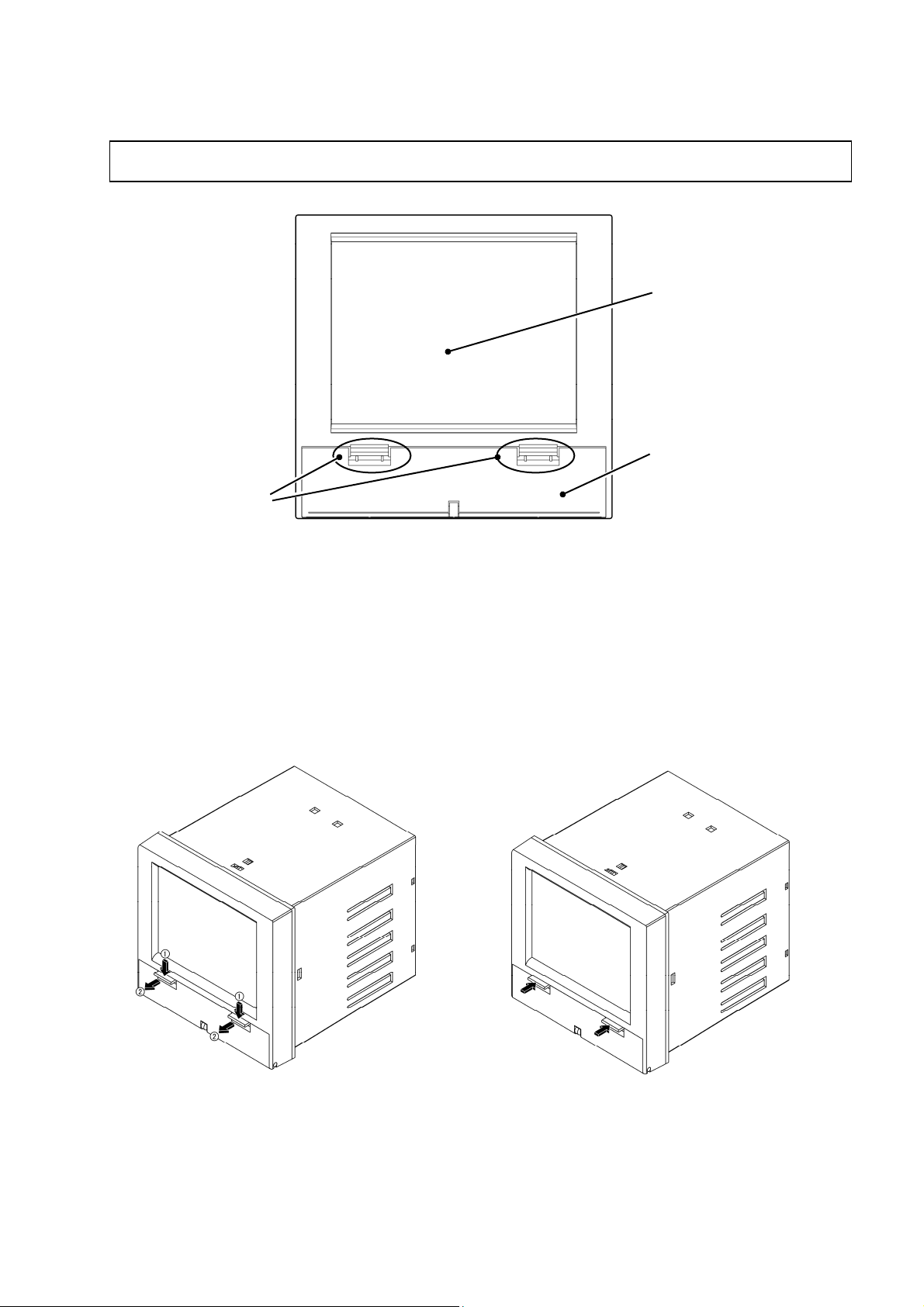
2. NAMES AND FUNCTIONS OF PARTS
2.1 Names and functions of parts
①
Display area
Knob
The LCD is provided with touch panel. Display the measurement data and other various
Parameter set screens. Touch the surface to set data.
② Button operation part cover
This panel protects the button operation part. It pulls it forward while pushing two knobs below to
appear function keyboard.
Note: Please do the both hands to the opening and shutting of cover. It causes damage.
【When opening cover of button operation part】 【When closing cover of button operation part】
①Display Unit
②Button op
eration part cover
2-1
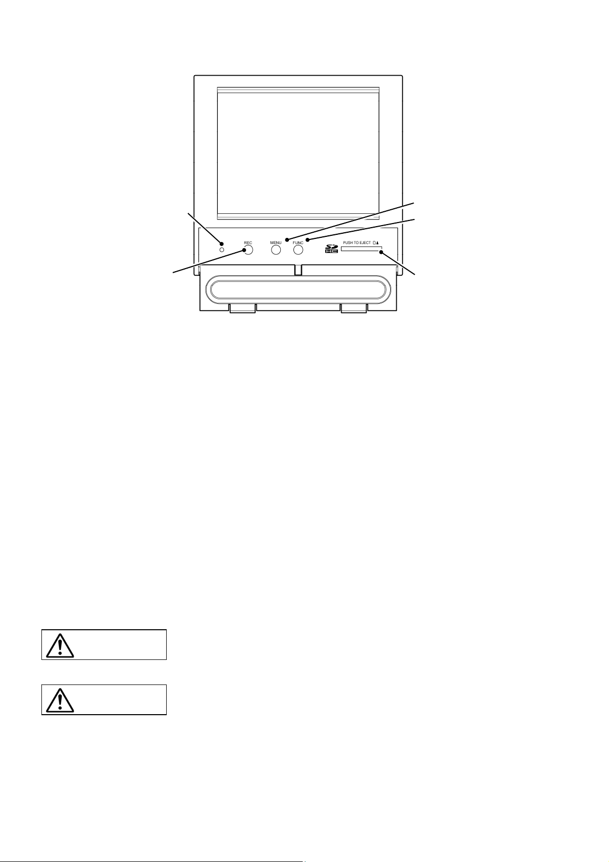
③Status display lamp
④REC button
Status display lamp
③
Allow the power ON/OFF, LCD (display) ON/OFF and record status to be displayed.
Lamp ON (highlighted) :Power ON, recording suspended
Lamp blinks(1 sec ON/1 sec OFF):Power ON, recording in progress
Lamp blinks(high speed) :Power ON, SD card writing
Lamp OFF :Power OFF
④ REC button
Used to start or stop recording.
⑤ MENU button
Display the menu screen.
Used to the continuance of record when check screen of stops recording.
⑥ FUNC button
The content of operation is allocated, and the operation can be done. It can select the “Change
display”, “Capture” and “Message”.
Select “OFF”, when you use as a start/a stop of Sub record.
⑦ SD card slot
Used for inserting the SD card.
To remove the SD card from the slot, press SD card to insert.
CAUTION
CAUTION
⑤MENU button
⑥FUNC button
⑦SD card slot
Please confirm the direction to the insertion of SD card. When forcibly
inserting it in a wrong direction, SD card and the main body are destroyed.
When you pull out the SD card while recording, it becomes impossible to
record data normally and causes past preservation data to destroy. Please
pull out the SD card after stopping recording.
2-2
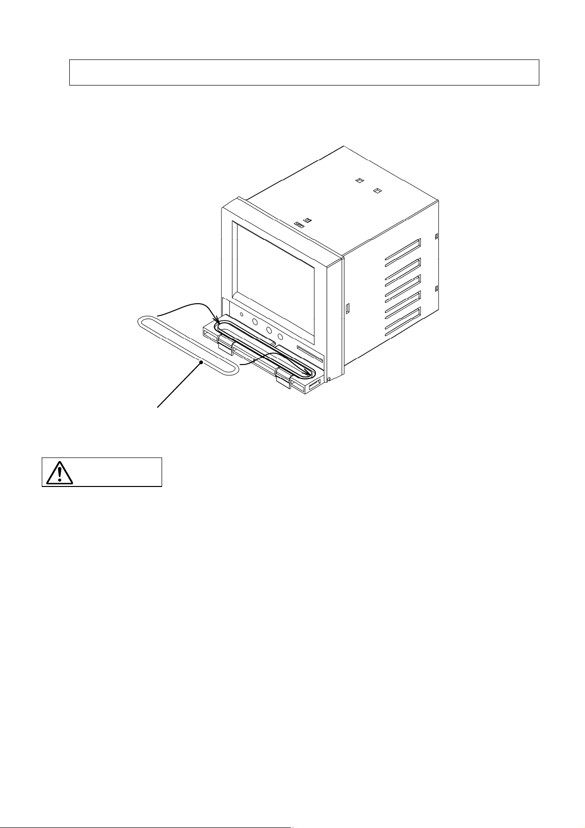
2.2 Set of O-ring for waterproof
When the factory is shipped, O-ring for the waterproof is not installed. When the waterproof and
dustproof uses it by the necessary environment, please install it according to the figure below.
O-ring for waterproof
CAUTION
It is not abnormal though the opening and shutting operation of the cover
becomes very hard if O-ring for the waterproof is installed.
2-3
3. INSTALLATION
3.1 Installation place
Install place
This equipment is a structure that is installed in the panel and used.
Please choose and install the following places.
・ Place without vibration and impact.
Place where dust and causticity gas are few.
・
Place where ambient temperature doesn't exceed 0 ~ 50℃, and place where temperature
・
change is a little.
Place where high radiant heat is not received directly.
・
・ Place where drop of water doesn't hang within the range of humidity 20 ~ 80%RH, and place
where dewfall is not done.
・ Place where circulation of air is good.
・
Place where space to be able to facilitate wiring, maintenance and
check, can be taken.
Place where electromagnetic radiation is not generated.
・
Place where doesn't include flammable gas, firedamp, causticity gas (SO2, H2S).
・
・ Place where machinery vibration is a little.
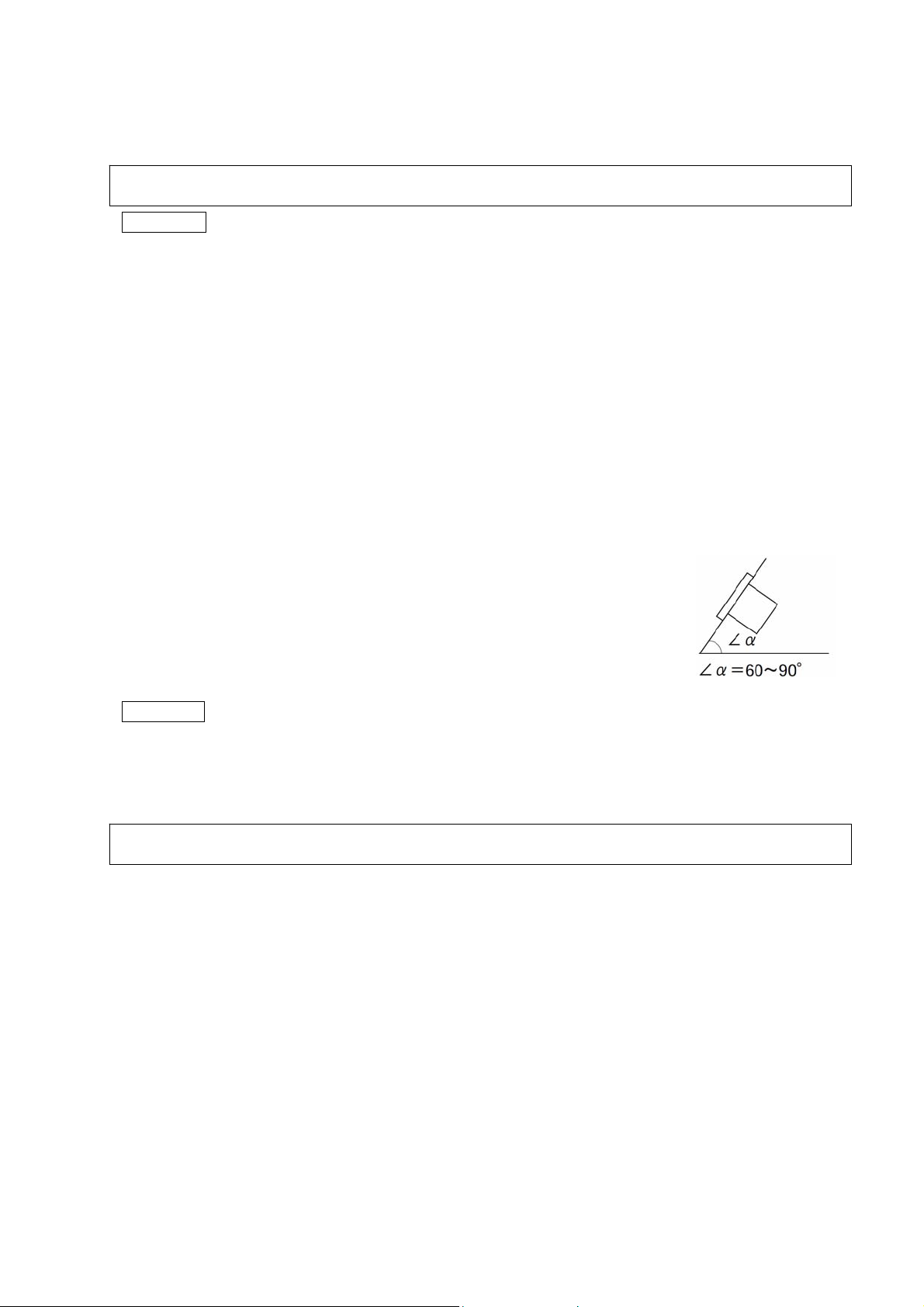
The inclination at the installation must not incline at the right and the
・
left, and it become the horizontal.
(Inclining forward 0°,Backward tilting 0 ~ 30°)
Install Panel
・The installation panel is recommended to use the steel board whose thickness is 1.2 mm or more.
・
The thickness of the installation panel is 7 mm or less.
3.2 Installation on panel
Please put and install appended panel packing between the recorder and the panel.
Refer item 9.16 for externals size.
3-1
4. WIRING
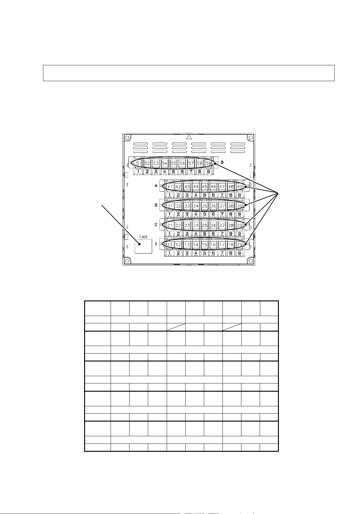
4.1 Terminal stand array and LAN connector
The terminal stand is one row in the uppermost part, and 4 rows or less are in the lower side for the
analog input and option.
The part of “Terminal No.41
mounted.
LAN connector
Terminal
No.
Name POW NC COM ALM NC RS-485
Sign L N G A C + -
Terminal
No.
CH. 10 11 12
Input +/A -/B V/B +/A -/B V/B +/A -/B V/B
Terminal
No.
CH. 7 8 9
Input +/A -/B V/B +/A -/B V/B +/A -/B V/B
Terminal
No.
CH. 4 5 6
Input +/A -/B V/B +/A -/B V/B +/A -/B V/B
Terminal
No.
CH. 1 2 3
Input +/A -/B V/B +/A -/B V/B +/A -/B V/B
Fig. 4-1 Terminal stand array(The back of recorder)
~ 49” becomes a connector for the type that the DI/DO of option is
Terminal No.
51 52 53 54 55 56 57 58 59
41 42 43 44 45 46 47 48 49
31 32 33 34 35 36 37 38 39
21 22 23 24 25 26 27 28 29
11 12 13 14 15 16 17 18 19
4-1
4.2 Wiring for power supply Wiring for power supply
[Power supply terminal] [Power supply terminal]
Power suppl
Power supply terminal is “Terminal No. 51 ~ 53”.
[Wiring procedure] [Wiring procedure]
①
① The protection cover of the transparency of the terminal stand is removed. It pulls forward while
The protection cover of the transparency of the terminal stand is removed. It pulls forward while
pushing the hook of two places of one side of cover part internally at the same time and it removes.
pushing the hook of two places of one side of cover part internally at the same time and it removes.
②
The cable is connected with the power supply terminal. The protective grounding is connected with
The cable is connected with the power supply terminal. The protective grounding is connected with
②
terminal No.53(G). Non-earth side of the power supply is connected with terminal No.51(L), and the
terminal No.53(G). Non-earth side of the power supply is connected with terminal No.51(L), and the
earth side of the power supply is connected with terminal No.52(N).
earth side of the power supply is connected with terminal No.52(N).
The protection cover of the transparency is installed. ③ The protection cover of the transparency is installed.
③
It is confirmed that the protection earth is correctly done. ④ It is confirmed that the protection earth is correctly done.
④
Warning
① Please energize to this equipment after doing the protection earth without fail for the
electric shock prevention.
Please do not cut the protective earth, and please do not remove connecting wires of the
②
protective earth.
Please confirm the power-supply voltage of this equipment is corresponding to the
③
voltage of the power supply.
Please energize to this equipment after applying the protection cover of the transparency.
④
CAUTION
① Please use the one that corresponds to 600V vinyl insulation electric wire (JIS C3307)
or it for the electric wire for the power supply.
② Please install round shape pressure connection terminal (for M3.5) to which the
insulation sleeve adheres on the electric wire terminal.
Please connect it with the protective earth terminal by the third kind or more (Earth
③
resistance under 100Ω, Minimum thickness of ground line 1.6 mm).
④ When you share the protective earth conductor with other equipment, the influence of the
noise from the ground line might be received. Sharing with other equipment is
recommended to be avoided.
⑤ Please install the circuit breaker and the switch, etc. for safety, and specify that these are
the cutting switches of the Recorder in the power supply wiring.
⑥ The voltage rating must use the main source of electrical power in the variation range in
±10%.
⑦ A transitional current might flow to the main source of electrical power when the power
supply is turned on.
y terminal is “Terminal No. 51 ~ 53”.
51 51
L N G
52 52 53 53
4-2
4.3 Wiring for analog input
[Analog input terminal]
Analog input terminal is “No.11
number of input channels.
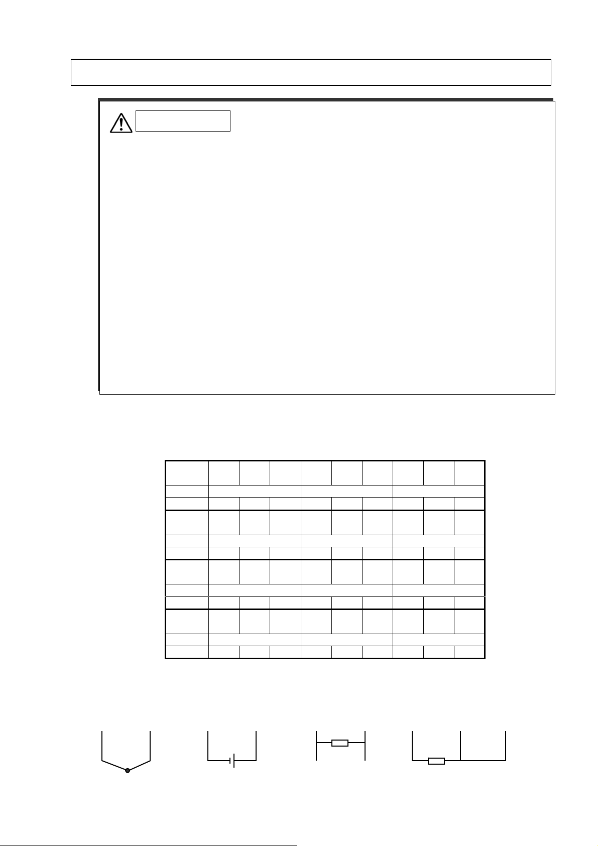
[Details of terminal array of each input of CH.1~12]
<TC・mV> <V> <mA> <RTD>
+ - - V A B B
CAUTION
① Notes of input wire
・ Please do not mix the noise about the input wiring. Moreover, the use of an effective shield
line or twist line is recommended to the noise in the input wiring.
・ At the thermo-couple input, please connect thermoelectricity vs. wire directly or use the
protective conductor. The use of the input line with the shield is recommended.
・ At the resistance temperature sensor input, the difference of the line resistance in three lines
is assumed below the following. The use of the input line with the shield is recommended.
Pt100, JPt
・ When there is a possibility of receiving the
when wiring near the high frequency power supply, the use of the twist line with the shield
is recommended.
・Please install round shape pressure connection terminal (for M3.5) to which the insulation
sleeve attaches on the electric wire terminal.
② Notes in wiring
・ Please separate from the power supply circuit (power supply or DO circuit of 25V or more)
and use this equipment and wiring between measurement points.
・ Please short-circuited of the input terminal not used.(mV, V, Thermo-couple, is short-circuited
+~-. Resistance temperature sensor is short-circuited A, B, B)
・ Please ground the shield of the shield line.
100: Under 50mΩ.
influence by the inductive noise, especially,
~ 49”. The number of terminals is different depending on the
Terminal
No.
CH. 10 11 12
Input +/A -/B V/B +/A -/B V/B +/A -/B V/B
Terminal
No.
CH. 7 8
Input +/A -/B V/B +/A -/B V/B +/A -/B V/B
Terminal
No.
CH. 4 5
Input +/A -/B V/B +/A -/B V/B +/A -/B V/B
Terminal
No.
CH. 1 2
Input +/A -/B V/B +/A -/B V/B +/A -/B V/B
41 42 43 44 45 46 47 48 49
31
21
11
32 33 34 35 36 37 38 39
9
22 23 24 25 26 27 28 29
6
12 13 14 15 16 17 18 19
3
- V
(250Ω shunt resistance
connection)
4-3
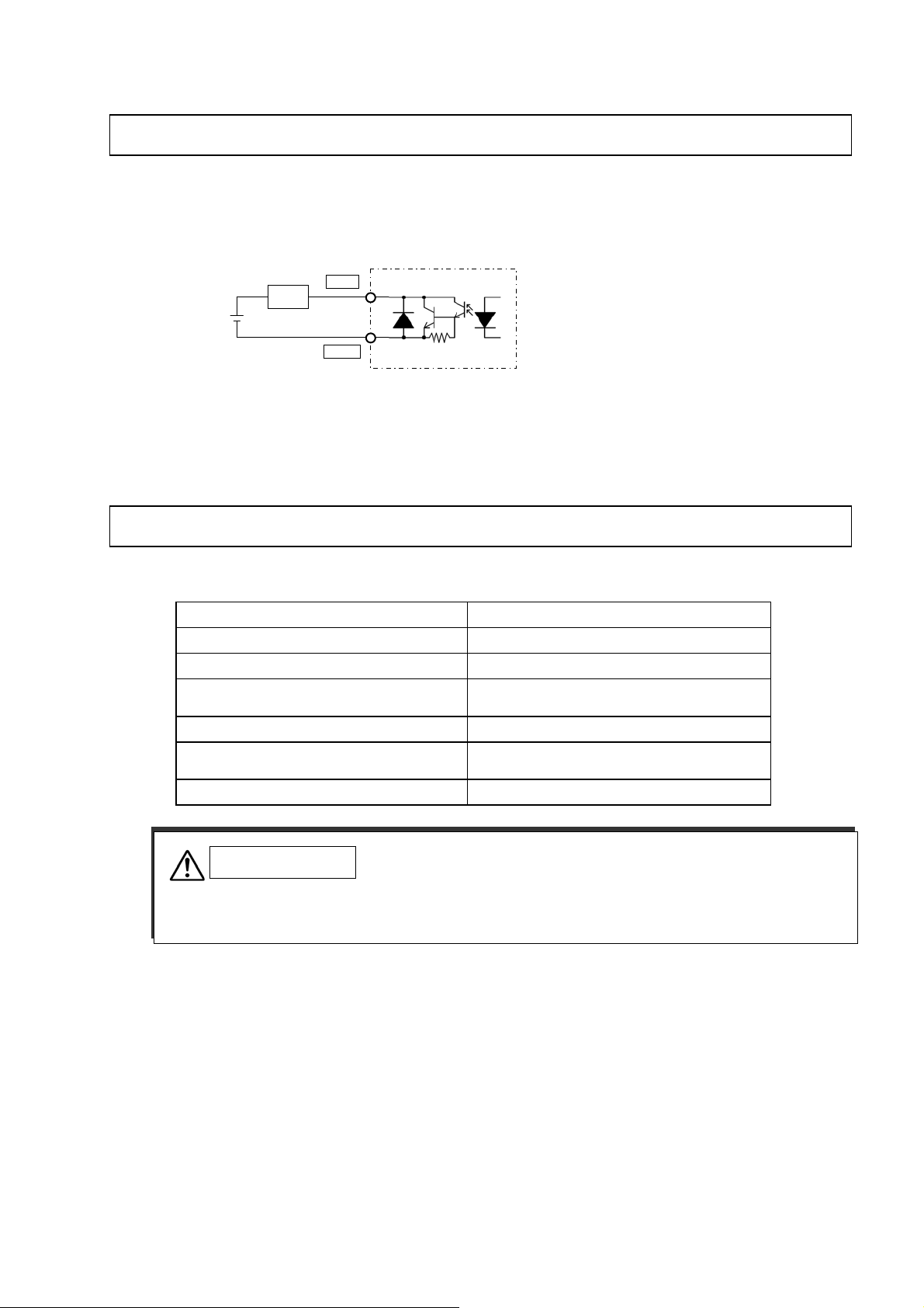
4.4 Wiring for COM ALM
COM ALM can be used as an alarm output of measurements etc.
[Schematic diagram]
V
+5~30
Load
ALM
COM
Open collector output(1 point)
Point of contact ratings:30V DC 20mA/1 point
4.5 Wiring for LAN cable
[Communication specification]
Specification 10BASE-T
Transmission speed 10Mbps
Transmission scheme Baseband
The maximum network length or
The maximum node interval
The maximum segment length 100m(Between the node and HUB)
Connecting cable
Protocol TCP/IP
CAUTION
・ To avoid the influence of the inductive noise, LAN cable, please separate from the power
supply line and strong electricity line as much as possible.
500m(Cascade 4 steps)
UTP(Twisted pair who doesn't have shield)
22-26AWG
[Connection with personal computer]
Please connect it through HUB.
Please use the cross cable when connecting it directly with the personal computer.
4-4

4.6 Wiring for DI/DO (Option)
DI/DO becomes a connector joint.
[Pin array]
Pin No. Signal name Pin No. Signal name
1 DI1 21 DO1
2 DI2 22 DO2
3 DI3 23 DO3
4 DI4 24 DO4
5 DI5 25 DO5
6 DI6 26 DO6
7 DI7 27 DO7
8 DI8 28 DO8
9 DI9 29 DO9
10 NC 30 DO10
11 NC 31 DO11
12 NC 32 DO12
13 DI_COM 33 DO_COM
14 DI_COM 34 DO_COM
15 DI_COM 35 DO_COM
16 DI_COM 36 DO_COM
17 DI_COM 37 DO_COM
18 DI_COM 38 DO_COM
19 DI_COM 39 DO_COM
20 DI_COM 40 DO_COM
DI/DO connector
4-5
 Loading...