


0
RM10C
HYBRID RECORDER
COMMUNICATION COMMAND
INSTRUCTION MANUAL
HXPRM10mnC0005E
Jan. 2016 (2nd Edition)
All Rights Reserved, Copyright © 2004-2016, Ohkura Electric Co., Ltd.
― ―
HXPRM10mnC0005E
1
For safety using
Symbols used on the instrument
This shows “Caution for handling”. This symbol is used on the parts need to
reference the instruction manual for saving human body and the instrument.
This shows “Protective grounding”. Be sure to provide protective grounding prior
to operate this instrument.
This shows “Risk of electric shock”. This symbol is used on the parts, which has
a risk of electric shock.
Be sure to observe the following warnings/cautions and those provided in the text
in order to secure safety in handling the instrument.
WARNING
In order to prevent electric shock; be sure to disconnect this instrument from
the main power source when wiring it.
(1) In order to prevent an electric shock; be sure to provide protective
grounding prior to turning on this instrument.
(2) Do not cut a protective grounding conductor or disconnect protective
grounding.
(1) Make sure that the supply voltage for this instrument conforms to the
voltage of the supply source.
(2) Attach a protective cover prior to turning on this instrument.
Do not operate this instrument in the environment where it is exposed to a
combustible/explosive/corrosive gas or water/steam.
Provide input and output wiring after turning off the power.
全般
General
全般
Protective Grounding
全般
Power Source
全般
Working Environment
全般
Input and Output Wiring
Thank you for purchasing our RM10C Hybrid Recorder.
In order to this instrument to exhibit all of its functions effectively and correctly, read and understand this
instruction manual thoroughly before using the instrument.
The symbols below are used on this instrument for the cautioning information.
― ―
HXPRM10mnC0005E

2
CAUTION
Do not use empty terminals for other purposes such as relaying, etc.
When transporting this instrument or the equipment with this instrument
incorporated in it, take measures to prevent opening the door and falling out the
inner module.
Do not touch the switches, etc. inside this instrument. Also, do not replace the
main unit or PRINTed circuit boards. When this is neglected, we cannot
guarantee functioning of the instrument. Contact our dealer where you
purchased the instrument, or our sales representative.
[Note]
(1) Deliver this instruction manual to an end user.
(2) Prior to handling this instrument, be sure to read this manual.
(3) If you have any questions on this manual or find any errors or omissions in
this manual, contact our sales representative.
(4) After reading this manual, keep it carefully by the instrument.
(5) When the manual is lost or stained, contact our sales representative.
(6) It is prohibited to copy or reproduce this manual without our permission.
(1) When installing this instrument, put on a protective gear such as safety
shoes, helmet, etc. for your safety.
(2) Do not put your foot on the installed instrument or get on it, because it is
dangerous.
Only our serviceman or persons authorized by our company are allowed to
remove and take the inner module, the main unit and PRINTed circuit boards
apart.
(1) Dispose the replaced batteries in a correct way.
(2) Do not incinerate plastics of maintenance parts and replacement parts. A
harmful gas may be produced.
(1) Use dry cloth to clean the surface of this instrument.
(2) Do not use any organic solvent.
(3) Cleaning the instrument after turning off the power.
This instruction manual is subject to change without prior notice.
全般
Input and Output Wiring
全般
Transportation
全般
Inside of Instrument
全般
Instruction Manual
全般
Installation
全般
Maintenance
全般
Disposal
全般
Cleaning
全般
Revisions
― ―
HXPRM10mnC0005E
3
Using procedure for this manual
Chapter and TITLE
For purchase
and install
For initial
setting and
change setting
For daily
operation
For using
communication
For
maintenance
and
trouble-shootin
g
For safety using (page 1)
◎ ◎ ◎ ◎ ◎
1. INTRODUCTION
◎
◎
Original protocol
2. THE RECEPTION OF
DATA
○ ◎ ○
3. DATA TRANSMISSION
○
◎
○
4. NOTE OF DATA
COMMUNICATION
○ ◎ ○
ModbusRTU protocol
5. OVERVIEW
○
◎
○
6. DATA TRANSMISSION
AND RECEPTION
○ ◎ ○
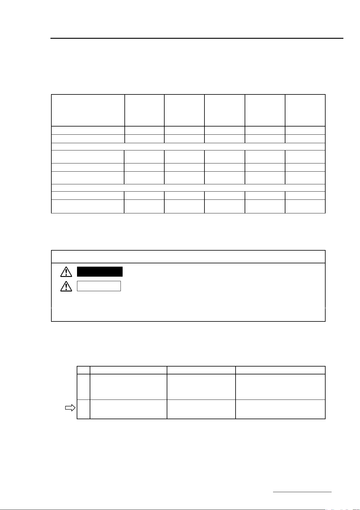
Symbols used on this manual
WARNING
Failure to observe this information could result in death or injury.
Be absolutely certain to read this.
CAUTION
Failure to observe this information could damage the instrument.
Be certain to read it.
[Note]
This is cautionary information for correct use of the instrument.
Be certain to read it.
[Reference]
This is information to help you use the functions of this instrument more
effectively.
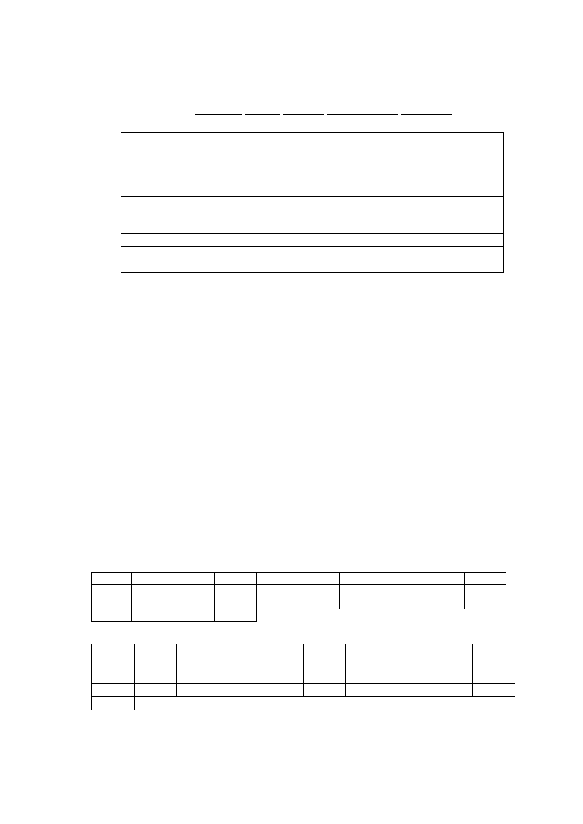
Name
Part No.
Outline
1
RM10C Hybrid Recorder
instruction manual
HXPRM10mnC0001E
HXPRM10mnC0002E
Explanation for installing, wiring,
standard operation. And setting
or operation for using this
instrument.
2
RM10C Hybrid Recorder
Communication Command
instruction manual
HXPRM10mnC0005E
Explanation for reading and
writing data of the recorder by
communication function.
This
manual
1.Using procedure
This instruction manual consists of “For safety using”, “Contents” and “Chapter 1 to Chapter 6” as bellow.
Read the applying sections for your purpose to use this instrument.
◎ :Be absolutely certain to read this.
○ :Be certain to read this if you need.
The symbols below are used on the warning and cautioning information in this manual.
2.Guide of Instruction manual
The instruction manuals of this instrument are as the table below.
― ―
HXPRM10mnC0005E

4
CONTENTS
1. INTRODUCTION ......................................................................................................................... 5
1.1 General Description ............................................................................................................. 5
1.2 Difference in RS-485, RS-232C ........................................................................................... 5
1.3 Original Protocol - Basic item about the command .............................................................. 5
1.4 Basic item about the Modbus RTU protocol ......................................................................... 6
2. ORIGINAL PROTOCOL - THE RECEPTION OF THE DATA ..................................................... 7
2.1 Setup command ................................................................................................................... 7
2.1.1 Setup command list .................................................................................................. 7
2.1.2 Setting of INPUT RANGE/RECORD SPAN .............................................................. 8
2.1.3 Setting of Alarm ...................................................................................................... 11
2.1.4 Setting of the Unit ................................................................................................... 11
2.1.5 Setting of the 1st chart speed ................................................................................. 11
2.1.6 Setting of the date/time ........................................................................................... 12
2.1.7 Copying the Setting Data of the channel ................................................................ 12
2.1.8 Setting of the Printing cycle(Multipoint type only) ................................................... 12
2.1.9 Setting of the Zone Recording ............................................................................... 12
2.1.10 Setting of the Partial Compression/Expansion ........................................................ 13
2.1.11 Setting of the Digital Print ON/OFF ......................................................................... 13
2.1.12 Setting of the Tag Character ................................................................................... 13
2.1.13 Setting of the Comment Character ......................................................................... 14
2.2 Control command............................................................................................................... 15
2.2.1 Control command list .............................................................................................. 15
2.2.2 Recording Start/Stop .............................................................................................. 16
2.2.3 Manual Print Start/Stop ........................................................................................... 16
2.2.4 List Print Start/Stop ................................................................................................. 16
2.2.5 Engineering list Print Start/Stop .............................................................................. 16
2.2.6 Choice of the display contents. ............................................................................... 17
2.2.7 Communication comment print out ......................................................................... 17
3. ORIGINAL PROTOCOL - DATA TRANSMISSION ................................................................... 18
3.1 Getting the Set Value ......................................................................................................... 18
3.2 Data Reception Example ................................................................................................... 18
4. ORIGINAL PROTOCOL - NOTES OF COMMUNICATION ....................................................... 19
4.1 Half-Duplex Transmission .................................................................................................. 19
4.2 Multiple access .................................................................................................................. 19
4.3 Continuation of Opening the Link ....................................................................................... 19
4.4 Outputting the Status ......................................................................................................... 19
5. MODBUS RTU PROTOCOL - OVERVIEW ............................................................................... 20
5.1 Modbus RTU Protocol ........................................................................................................ 20
5.2 Add new items and Map version ........................................................................................ 20
6. MODBUS RTU PROTOCOL - DATA TRANSMISSION AND RECEPTION ............................... 21
6.1 Communication Protocol .................................................................................................... 21
6.2 Function codes .................................................................................................................. 21
6.3 Error response ................................................................................................................... 21
6.4 Reading of input register area ............................................................................................ 22
6.4.1 Reading of input register area ................................................................................ 22
6.4.2 Input Register Area Map ......................................................................................... 23
6.5 Reading and writing of the holding register area ................................................................ 26
6.5.1 Reading of the holding register area ....................................................................... 26
6.5.2 Writing of the holding register area (Single) ............................................................ 27
6.5.3 Writing of the holding register area (Continuation) ................................................. 28
6.5.4 Holding register area map ...................................................................................... 29
6.5.5 Holding register area setting range detail ............................................................... 35
― ―
HXPRM10mnC0005E

5
1. INTRODUCTION
Omission is possible
contents
Wiring and
communication
procedure
Request
measurement
value
Setting of the
recorder
Control of the
recorder
RM10C Hybrid Recorder
instruction manual
(HXPRM10mnC0001E,
HXPRM10mnC0002E)
○
○
RM10C Hybrid Recorder
Communication Command
instruction manual
(HXPRM10mnC0005E)
○
○
1.1 General Description
This instruction manual describes the communication command of the RM10C Recorder. Please refer to the
instruction manual (HXPRM10mnC0001E, HXPRM10mnC0002E) for the transmission of the measurement
data, a setup of communication and wiring.
1.2 Difference in RS-485, RS-232C
There is no difference between RS-232C and RS-485 about the communication command in this Recorder.
But, wiring and signal level are different.
1.3 Original Protocol - Basic item about the command
The communication command consists of a command distinction code, a parameter, delimiter(comma),
and terminator. The format of the command is as follows.
(Example) SR02 VOLT,200mV,0,20000 (terminator)
Command distinction code:
This code is defined by two characters the capital letter. (Exp. SR)
If the command needs a channel number, a channel number is described behind the
distinction code.
Parameter: Each parameter is divided with comma.
All the setting value is shown with the integer. (The plus sign can be omitted.)
The space character in the input parameter is ignored. The other side, the space
character in the unit code, the comment printout code and the tag printout code isn't
ignored. The parameter can be omitted unless the parameter is varied. But, a comma(,)
can't be omitted. Comma which is in front of the terminator can be omitted.
(Example)SR02,VOLT,,,(CR)(LF)
― ―
The date parameter, the time parameter and the channel number parameter have fixed
length. When that parameter length is different, these data induce errors.
(1) Date YY/MM/DD (8 characters)
(2) Time HH:MM:SS (8 characters)
(3) Channel Number: CHXX (2characters)
HXPRM10mnC0005E

6
1.4 Basic item about the Modbus RTU protocol
Modbus protocol is a Modicon Inc. (AEG Schneider Automation International SAS) is a communication
protocol that was developed for the PLC, are listed in the protocol specification (PI-MBUS-300 Rev.J).
Please refer to the same specification for the specification of the Modbus protocol.
In this manual, we describe the function code and data content of mainly Modbus protocol that can be used
in the present equipment.
― ―
HXPRM10mnC0005E

7
2. ORIGINAL PROTOCOL - THE RECEPTION OF THE DATA
Table 2.1 Setup command list
Command
Setting item
The number of
the parameters
Contents of a parameter
SR
Setting the range
MAX 7
Channel,Mode,Range(Reference
Channel)
Span lower limit value.
Span higher limit value.
Scaling lower limit value.
Scaling higher limit value
SA
Setting the Alarm
7
Channel,
Alarm level
Alarm on/off
Alarm type,Alarm set point
Relay on/off、Relay No.
SN
Setting the Unit
2
Channel, Unit
SC
Setting
the Chart Speed
1
1st Chart speed
SD
Setting the Date/Time
2
Date, time
SF
Setting
the Digital Print
2
Channel
Digital print on/off
ST
Setting the Tag
2
Channel, Tag characters
SG
Setting the Comment
2
Comment number,
Comment characters
SZ
Setting
the Zone recording
3
Channel, Left position,
Right position
SP
Setting the Partial
Compression/Expansion recording
4
Channel, Partial on/off
Compression
Expansion
SE
Setting
the Chart Speed
1
2nd chart speed
SY
Copying
the Setting data
2
Copy-from channel
Copy-to channel
SS
Setting
the recording cycle
1
Recording Cycle
(Multipoint type only)
2.1 Setup command
2.1.1 Setup command list
― ―
HXPRM10mnC0005E

8
2.1.2 Setting of INPUT RANGE/RECORD SPAN
Refer to table 2.2.
The input range and record span of each channel is set up as follows.
<Format>
SR(CH),(Mode),(Pr1),(Pr2),(Pr3),(Pr4),(Pr5),(Pr6),(Pr7)(CR)(LF)
CH: Specify the channel number to set.
Mode: The input mode is set up.
PrN: The number of PrN varies depend on the contents of Mode.
(1) Setting of the record skip.
The record of the channel, which specified with CH is stopped.
(The pen of pen type recorder is fixed on the zero point.)
CH:Setting Channel 01~06(The pen type is 01~02.).
Mode:SKIP
Example)SR05,SKIP(CR)(LF)
The 5th channel doesn't record.
(2) Setting of the Voltage, the Current, the Thermocouple or the RTD input range.
CH:Setting Channel 01~06(The pen type is 01~02.).
Mode:VOLT,TC or RTD
Pr1:Range
Pr2:Left end(Zero Input Value) Refer to table 2.2.
Pr3:Right end(Span Input Value)
Example)SR02,TC,K,0,3000(CR)(LF)
The input of 2nd channel is recorded in Thermocouple type K 0.0-300.0 ℃
(3) The setting of Difference/Sum/Mean operation.
CH:Setting Channel 01~06(The pen type is 01~02.).
Mode:DELT,SIGM or MEAN
Pr1:Refference Channel
・Choose a smaller channel than CH.
・The reference channel must be VOLT, TC, RTD or SCL mode.
Pr2:Left end(Zero Input Value)
Pr3:Right end(Span Input Value)
― ―
Example)SR05,02,DELT,0,3000(CR)(LF)
The output of the 5th channel shows a difference between the input of the 5th channel and
the 2nd channel (CH5-CH2). In this case, the input range of 5th channel becomes the
same as 2nd channel.
HXPRM10mnC0005E

9
(4) The setting of Scaling.
[CAUTION]
Pr5 - 7 can be omitted. If you omit the parameters, three parameters must be omitted
simultaneously.
[CAUTION]
Pr5 - 7 can be omitted. If you omit the parameters, three parameters must be omitted
simultaneously.
Refer to table 2.2.
Refer to table 2.2.
Refer to table 2.2.
CH:Setting Channel 01~06(The pen type is 01~02.).
Mode:SCL
Pr1:VOLT, TC, RTD
Pr2:Scaling Mode
Pr3:Left End(Zero Input Value)
Pr4:Right End(Span Input Value)
Pr5:Scaling Left End
Pr6:Scaling Right End
Pr7: Decimal point position(0~4)
Example)SR04,SCL,RTD,PT,0,3000,0,30000,2(CR)(LF)
[CAUTION]
Pr5 - 7 can be omitted. If you omit the parameters, three parameters must be omitted
simultaneously.
(5) The setting of Square Root
CH:Setting Channel 01~06(The pen type is 01~02.).
Mode:SQRT
Pr1:Range(Only VOLT Input)
Pr2:Left End(Zero Input Value)
Pr3:Right End(Span Input Value)
Pr4:Scaling Left End
Pr5:Scaling Right End
Pr6:Decimal point position(0~4)
Example)SR03,SQRT,mA,400,2000,0,10000,2(CR)(LF)
※Pr5 - 7 can be omitted. If you omit the parameters, three parameters must be omitted
simultaneously.
(6) The setting of Decade
CH:Setting Channel 01~06(A pen type is 01~02.).
Mode:DECAD
Pr1:Range(Only VOLT Input)
Pr2:Left End(Zero Input Value)
Pr3:Right End(Span Input Value)
Pr4:Scaling Left End
Pr5:Scaling Right End
Example)SR01,DECAD,10mV,0,1000,10E+01,10E+06(CR)(LF)
― ―
HXPRM10mnC0005E

10
Table 2.2 Setting range
Input
Range
Range or
Scaling
Mode
Zero Input
Value
(Left End)
Span Input
Value
(Right End)
Decimal
Point
(Fixation)
Note
VOLT
10mV
-1000
1000
2
±10mV
20mV
0
2000
2
0~20mV
50mV
0
5000
2
0~50mV
200mV
-2000
2000
1
±200mV
1V
-1000
1000
3
±1V
5V
0
5000
3
0~5V
10V
-10000
10000
2
±10V
mA
400
2000
2
4~20mA
TC
B
0
18200
1
0~1820℃
320
33080
1
32~3308゚F
R
0
17600
1
0~1760℃
320
32000
1
32~3200゚F
S
0
17600
1
0~1760℃
320
32000
1
32~3200゚F
K
-2000
13700
1
-200~1370℃
-3280
24980
1
-328~2498゚F
E
-2000
8000
1
-200~800℃
-3280
14720
1
-328~1472゚F
J
-2000
11000
1
-200~1100℃
-3280
20120
1
-328~2012゚F
T
-2000
4000
1
-200~400℃
-3280
7520
1
-328~752゚F
C
0
23200
1
0~2320℃
320
42080
1
32~4208゚F
Au-Fe
10
3000
1
1~300K
N
0
13000
1
0~1300℃
320
23720
1
32~2372゚F
PR40-20
0
18800
1
0~1880℃
320
34160
1
32~3416゚F
PLII
0
13900
1
0~1390℃
320
25340
1
32~2534゚F
U
-2000
4000
1
-200~400℃
-3280
7520
1
-328~752゚F
L
-2000
9000
1
-200~900℃
-3280
16520
1
-328~1652゚F
RTD
Pt100
-2000
6500
1
-200~650℃
-3280
12020
1
-328~1202゚F
JPt100
-2000
6300
1
-200~630℃
-3280
11660
1
-328~1166゚F
Example)When decimal point position is "1", the input value "1000" is recognized as "100.0".
― ―
HXPRM10mnC0005E
11
2.1.3 Setting of Alarm
Item
Contents
Setting Range
Note
CH
Channel number
01~06(multi)
01~02(pen)
LEVEL
Alarm Level
1~4
ON/OFF
Alarm ON/OFF
ON or OFF
It can be omitted.
TYPE
Alarm Type
H:Upper-limit
L:Lower-limit
It can be omitted.
VALUE
Set Value
It can be omitted.
RLY ON/OFF
Relay ON/OFF
ON or OFF
It can be omitted.
RLY No.
Relay No.
I01~I06(multi)
I01~I03(pen)
It can be omitted.
0 1 2 3 4 5 10
15
20
25
30
40
50
60
75
80
90
100
120
150
160
180
200
240
300
360
375
450
600
720
750
900
1200
1500
5
10
15
20
25
30
40
50
60
75
80
90
100
120
150
160
180
200
240
300
360
375
450
600
720
750
900
1200
1500
1800
2400
3000
3600
4500
4800
5400
6000
7200
9000
10800
12000
The Alarm of each channel is set up as follows.
<Format>
SA(CH),(LEVEL),(ON/OFF),(TYPE),(VALUE),(RLY ON/OFF),(RLY No.)(CR)(LF)
Part of underline can be omitted.
2.1.4 Setting of the Unit
The Unit of each channel is set up as follows.
<Format>
SN(CH),(UNIT)(CR)(LF)
CH:Setting Channel 01~06(The Pen type is 01~02.).
UNIT:The Unit is set up with the code as shown in table 2.3.( Within 6 characters.)
When you use the code beyond 7F
Please refer to the chapter 7.2.7 of the instruction manual (HXPRM10mnC0001E,
HXPRM10mnC0002E) for the data length setting.
2.1.5 Setting of the 1st chart speed
The 1st chart speed is set up as follows.
<Format>
SC(CHART SPEED)(CR)(LF)
The chart speed is chosen from the following table.
CHART SPEED (Multipoint type)
, the data length must be used as 8 bit.
HEX
― ―
CHART SPEED (Pen type)
HXPRM10mnC0005E

12
2.1.6 Setting of the date/time
The date/time of the internal watch of the recorder is set up as follows.
<Format>
SD(DATE),(TIME)(CR)(LF)
DATE:YY/MM/DD
(YY)Year 00~99
(MM)Month 01~12
(DD)Day 01~31
TIME:HH:MM:SS
(HH)Hour 00~23
(MM)Minute 00~59
(SS)Second 00~59
2.1.7 Copying the Setting Data of the channel
The setup data of the channel can be copied on other channels.
<Format>
SY(CHS),(CHD)(CR)(LF)
CHS:Copy-from Channel 01~05(The Pen type is 01 only.)
CHD:Copy-to Channel ( CHS < CHD )
The copy-to channel must set larger value than copy-from channel.
2.1.8 Setting of the Printing cycle(Multipoint type only)
The Printing cycle of the recorder is set up as follows.
<Format>
SS(PRINTING CYCLE)(CR)(LF)
PRINTING CYCLE: 10,20,30 and 60 (sec)
2.1.9 Setting of the Zone Recording
The Zone Recording of each channel is set up as follows.
<Format>
SZ(CH),(LEFTPOSITION),(RIGHTPOSITION)(CR)(LF)
CH:Setting Channel 01~06(The Pen type is 01~02.).
LEFTPOSITION:0~95%
RIGHTPOSITION:5~100%
Part of underline can be omitted. The original setup is inherited when it omits.
― ―
HXPRM10mnC0005E

13
2.1.10 Setting of the Partial Compression/Expansion
The Partial Compression/Expansion recording of each channel is set up as follows.
<Format>
SP(CH),(ON/OFF),(BOUNDARY POSITION),(BOUNDARY VALUE)(CR)(LF)
CH:Setting Channel 01~06(The Pen type is 01~02.).
ON/OFF:Partial Compression/Expansion function ON or OFF
BOUNDARY POSITION: 1~99%
BOUNDARY VALUE:
CH is VOLT,TC,RTD,DELT,SIGM or MEAN mode: In the span data
CH is SCALE,SQRT,DECAD mode: In the scale data
Part of underline can be omitted. The original setup is inherited when it omits.
2.1.11 Setting of the Digital Print ON/OFF
The Digital Print ON/OFF of each channel is set up as follows.
<Format>
SF(CH),(ON/OFF)(CR)(LF)
CH:Setting Channel 01~06(The Pen type is 01~02.).
ON/OFF: ON or OFF
2.1.12 Setting of the Tag Character
The Tag Character of each channel is set up.
<Format>
ST(CH),(TAG)(CR)(LF)
CH:Setting Channel 01~06(The Pen type is 01~02.).
TAG:The Tag Character is set up with the character code shown by the table 2.3.
( Multipoint type is within 7 characters. Pen type is within 5 characters.)
When you use the character code beyond 7F
function must be used as 8 bit. Please refer to the chapter 7.2.7 of the instruction manual
(HXPRM10mnC0001E, HXPRM10mnC0002E) for the data length setting.
, the data length of communication
HEX
― ―
HXPRM10mnC0005E

14
2.1.13 Setting of the Comment Character
2*
3*
4*
5*
6*
7*
A*
B*
C*
D*
E*
F*
*0
SP 0 @
P p
0
0
Π
π
*1 ! 1 A Q a q
1
1
Α Ρ α
ρ
*2 ″ 2 B R b r
2
2
Β Σ β
σ
*3 # 3 C S c s
3
3
Γ Τ γ
τ
*4 $ 4 D T d t
4
4
Δ Υ δ
υ
*5 % 5 E U e u
5
5
Ε Φ ε
φ
*6 & 6 F V f v
6
6
Ζ Χ ζ
χ
*7 ′ 7 G W g w
7
7
Η Ψ η
ψ
*8 ( 8 H X h x
8
8
Θ Ω θ
ω
*9 ) 9 I Y i y
9
9
Ι ι
*A * : J Z j z
Κ κ
*B + ; K [ k {
+
+
Λ λ
*C , < L ¥ l |
± Μ μ
*D
- = M ] m
}
Ν ν
*E
. > N ^ n
 ̄
-
-
Ξ ξ
*F / ? O _ o
o
o
Ο ο
The Comment Character to print by the Digital Input is set up.
<Format>
SG(Cn),(COMMENT)(CR)(LF)
Cn:Comment Number(1~3)
COMMENT:A Comment Character is set up with the character code shown by the table 2.3.
(Multipoint type is within 16 characters. Pen type is within 12 characters.)
When you use the character code beyond 7F
function must be used as 8 bit. Please refer to the chapter 7.2.7 of the instruction
manual (HXPRM10mnC0001E, HXPRM10mnC0002E ) for the data length setting.
Character Code Table
, the data length of communication
HEX
Table 2.3 Character Code Table
Example)The character code "43
― ―
" represents as the character "C".
HEX
HXPRM10mnC0005E

15
2.2 Control command
Table 2.4 Control command list
Command
Control Item
The number of
parameter
The explanation of operation
PS0
Recording Start
-
This command is the same as RUN key.
PS1
Recording Stop
-
MP0
Manual Print starting
-
This command is the same as key
operation of "Manual Print".
MP1
Manual Print stop
-
LS0
List Print starting
-
This command is the same as key
operation of "List Print".
LS1
List Print stop
-
SU0
Engineering List Print starting
-
This command is the same as key
operation of "Engineering List Print".
SU1
Engineering List Print stop
-
UD0
Chooses an Auto Display
-
When choosing the manual display,
channel number can be set.
But, the channel number can be omitted.
Exp.)Display the measurement value of
5th channel.
UD
1,05
(CR)(LF)
UD1
Chooses a Manual Display
1
UD2
Chooses a Date Display
-
UD3
Chooses a Time Display
-
UD4
Chooses a Display OFF
-
PR0
Communication comment print
out (Sync printout)
2
The printout of characters which is
received by the communication.
The parameter consist of printout colors
and the printout characters.
PR1
Communication comment print
out (Async printout)
2
BO0
Byte output order
(High byte earlier)
2
This command only affects the binary
mode.
(Please refer to the chapter 8 of the
instruction manual for details.)
(HXPRM10mnC0001E,
HXPRM10mnC0002E)
BO1
Byte output order
(Low byte earlier)
2
TS0
Chooses of the measurement
value output
-
This command chooses send data.
The send data actually uses
LF command, FM command.
(Please refer to the chapter 8 of the
instruction manual for details.)
(HXPRM10mnC0001E,
HXPRM10mnC0002E)
TS1
Chooses of the setting value
output.(Refer to Chapter 3)
-
TS2
Chooses of the decimal point
position and the unit character
output.
-
FM0
The ASCII output of the
measurement data.
2
This command outputs a measure-ment
value. The parameter consists of the
output starting channel and output
ending channel.
(Please refer to the chapter 8 of the
instruction manual for details.)
(HXPRM10mnC0001E,
HXPRM10mnC0002E)
FM1
The Binary output of the
measurement data.
2
LF
The output of the setting value,
the unit character and the
decimal point position.
2
This command outputs a setting value.
The parameter consists of the output
starting channel and output ending
channel.
(Please refer to the chapter 8 of the
instruction manual for details.)
(HXPRM10mnC0001E,
HXPRM10mnC0002E)
2.2.1 Control command list
― ―
HXPRM10mnC0005E

16
2.2.2 Recording Start/Stop
This command starts or stops recording of the recorder.
<Format>
PS0(CR)(LF) ・・・The recorder starts the record.
PS1(CR)(LF) ・・・The recorder stops the record.
2.2.3 Manual Print Start/Stop
This command starts or stops printing of the "Manual print".
<Format>
MP0(CR)(LF) ・・・The manual print is started.
MP1(CR)(LF) ・・・The manual print is stopped.
2.2.4 List Print Start/Stop
This command starts or stops printing of the "List print".
<Format>
LS0(CR)(LF) ・・・The list print is started.
LS1(CR)(LF) ・・・The list print is stopped.
2.2.5 Engineering list Print Start/Stop
This command starts or stops printing of the "Engineering list print".
<Format>
SU0(CR)(LF) ・・・The Engineering list print is started.
SU1(CR)(LF) ・・・The Engineering list print is stopped.
― ―
HXPRM10mnC0005E

17
2.2.6 Choice of the display contents.
This command chooses the display mode of the recorder.
The Auto Display, the Manual Display, the Date Display, the Time Display and Display OFF can be chosen.
When receiving this command, the display of recorder changes automatically.
<Format>
UD0(CR)(LF) ・・・・・Auto Display
UD1,(CH)(CR)(LF) ・・・・・Manual Display
UD2(CR)(LF) ・・・・・Date Display
UD3(CR)(LF) ・・・・・Time Display
UD4(CR)(LF) ・・・・・Display OFF
CH:The manual display channel 01~06(The Pen type is 01~02.).
The underline part can be omitted.
2.2.7 Communication comment print out
This command prints the character strings, which is received by the communication.
Please refer to table 2.3 for the character code. When you use the character code beyond 7FHEX,
the data length of communication function must be used as 8 bit. Please refer to the chapter 7.2.7
of the instruction manual (HXPRM10mnC0001E, HXPRM10mnC0002E ) for the data length setting.
<Format>
PR0,(COLOR),(TEXT)(CR)(LF) ・・・・・The Sync printout.
PR1,(COLOR),(TEXT)(CR)(LF) ・・・・・The Async printout.
COLOR:Choose a printout color. (The Pen type is only PRP.)
PRP:Purple RED:Red BLK:Black GRN:Green BRN:Brown BLU:Blue
TEXT:Maximum character number of Multipoint type is 47.
Maximum character number of Pen type is 21.
― ―
HXPRM10mnC0005E

18
3. ORIGINAL PROTOCOL - DATA TRANSMISSION
Order
Command
Description
1
PS
Recording/Stop
2
SR
Input range, recording span
3
SN
Unit 4 SA
Alarm
5
SC
1st chart speed
6
SS
Analog printing period
7
SZ
Zone recording
8
SP
Partial compression/expansion recording
9
SF
Digital printing
10
ST
Tag character
11
SG
Comment character
12
SE
2nd chart speed
13
UD
Display indication mode
14
EN
End
Send the set value in this order
Open command
Open the link
Set value data output
designation
command(TS1)
Prepares for
the set value
data output
Data update
command(ESC T)
Prepares for
the update
data
Data output request
command(LF)
Sends the
update data
Close command
Close the link
Send the command to the
recorder to which you want to
start data transmission.
When you want to get the set
value from same recorder
continuously, this is
unnecessary.
Send the command to the
recorder each time.
Send the command when you
want to send to other recorder.
3.1 Getting the Set Value
When the recorder receives "(TS1)+(ESC T)+(LF)", the recorder sends the setting value continuously
according to the following table 3.1.
The output formats of each command are as same as that of format when it set up.
Table 3.1 Order of the set value transmission
3.2 Data Reception Example
― ―
HXPRM10mnC0005E

19
4. ORIGINAL PROTOCOL - NOTES OF COMMUNICATION
4.1 Half-Duplex Transmission
The recorder side is the half-duplex transmission. The recorder cannot receive the data while sending
the data. When the host computer sends the next data, all the receiving data must be completed.
4.2 Multiple access
Don't open another recorder when one recorder is opened on the same line.
4.3 Continuation of Opening the Link
Don't take interval for a long time, after sending the open command.
The syntax error may occur when not sending data some time.
Be sure to send the close command "ESC C" when you do not use the communication.
If the syntax error occurs, send the status output command "ESC S" to reset the error.
(※ The close command cannot reset the syntax error.)
4.4 Outputting the Status
When the open-link recorder has a data error on its link, the recorder saves the error in the internal status
area as a communication error. The "ESC S" command can reads this status.
Issuing this command clears the on-going error. Refer to chapter 8.5 in the instruction manual.
(HXPRM10mnC0001E, HXPRM10mnC0002E)
Be sure to reset the error when data set to recorder. When no error reset, you may not be able to judge
command, which the error specify.
― ―
HXPRM10mnC0005E

20
5. Modbus RTU PROTOCOL - OVERVIEW
Item
Specification
Interface
RS-485/RS-232C
Protocol
Modbus RTU
Communication speed
1200 /2400 /4800 /9600 /19200/ 38400 [bps]
Parity
None/Even/Odd
Data length
8bit(※)
Stop bit
1bit / 2bit
Slave address
1~247(0 invalid)
Body version
Map version
Contents
Note
before Ver4.00
-
ModbusRTU is not available.
Ver4.00
01
The first release of the Modbus
RTU function.
[CAUTION]
In the old version, you can’t use features added in the new version.
In that case, there is a possibility that it does not work properly when reading / writing to
the address of the newly added function.
5.1 Modbus RTU Protocol
※ Please use in 8bit data length When using the ModbusRTU protocol.
Can’t be performed successfully communication If you using 7bit.
5.2 Add new items and Map version
Depending on the version up of the recorder, there is that the contents of the Modbus map is hanged.
If the Modbus map is modified, Modbus map version (address 30025) will also be updated.
Newly added setting items are available in the corresponding version or later. (Table below)
― ―
HXPRM10mnC0005E

21
6. Modbus RTU PROTOCOL - DATA TRANSMISSION AND RECEPTION
Slave address
(1byte)
Function code
(1byte)
Data
(variable)
CRC
(2byte)
Code
Function
Maximum
data length
Modbus original function (reference)
03H
Setting data read
123 words
Data read from holding register
04H
Input data read
123 words
Data read from input register
06H
One-time setting data write
1 words
Data write to holding register
10H
Continuous setting data writes
123 words
Data write to holding register
Configuration
Data length
Data
Slave address
1
-
Function code + 80H
1
86H
Error code
1
10H
Error check (Only for Modbus RTU)
2
CRC
Total number of bytes
5
-
Error
code
Description
Occurrence condition(s)
01H
Invalid function code
An unsupported function code is specified.
02H
Invalid register address
The relative address range exceeds "9999."
03H
Invalid number of registers
- The length of the accessed data is "0" or the sum of the
relative address and data length exceeds the limit.
- It is assumed that two or more function codes, each
executable for one area, are involved.
- Data longer than 2 words is specified for a one-time write
command.
- The data length exceeds 123 words.
04H
Device error
The received data is shorter than the predefined data length.
10H
Command error
An attempt at a write over an area exceeding the writable range.
6.1 Communication Protocol
This equipment is compatible with Modbus RTU protocol.
Data format of the protocol is as below. It is composed of slave address, function code,
data, and CRC section.
Modbus RTU Data format
6.2 Function codes
Function code that can be used in this equipment is as follows.
6.3 Error response
In accordance with the communication protocol for the pertinent function code, if an error occurs during
command transmission, an error response is returned in the fixed format described in this section.
■ Example of slave response (function code = 06H, command error = 10H)
●Error codes and their occurrence conditions.
― ―
HXPRM10mnC0005E

22
6.4 Reading of input register area
Component
Data
length
Data
Slave address
1
-
Function code
1
04H
Data
Relative start address (high-order)
1
00H
Relative start address (low-order)
1
32H
Read data count (high-order)
1
00H
Read data count (low-order)
1
02H
Error check
2
CRC (16 bits)
Total number of bytes
8
Component
Data
length
Data
Slave address
1
-
Function code
1
04H
Data
Number of data bytes
1
04H
Data 1 (high-order)
1
00H
Data 1 (low-order)
1
09H
Data 2 (high-order)
1
00H
Data 2 (low-order)
1
0AH
Error check
2
CRC (16 bits)
Total number of bytes
9
The input register area is a read-only area.
The current measured value and the current time are mapped. Specify the start
address (relative) and data count (assuming that one word is two bytes) of the data to be read.
6.4.1 Reading of input register area
Function code :04H
■ Example of master transmission (with a start address of 0032H and a data count of 2 words)
■ Example of slave response (with a start address of 0032H and a data count of 2 words)
― ―
HXPRM10mnC0005E

23
6.4.2 Input Register Area Map
Address
Relative
address
(HEX)
Name
Array
Content
Remarks
30001
0
Model type(1/8)
1
ASCII
Multipoint type :"MULTI"
30002
1
Model type(2/8)
2
Pen type :"PEN"
30003
2
Model type(3/8)
3
After the blank
30004
3
Model type(4/8)
4
30005
4
Model type(5/8)
5
30006
5
Model type(6/8)
6
30007
6
Model type(7/8)
7
30008
7
Model type(8/8)
8
30009
8
Software version(1/16)
1
ASCII
Version information on a system.
30010
9
Software version(2/16)
2
30011
A
Software version(3/16)
3
30012
B
Software version(4/16)
4
30013
C
Software version(5/16)
5
30014
D
Software version(6/16)
6
30015
E
Software version(7/16)
7
30016
F
Software version(8/16)
8
30017
10
Software version(9/16)
9
30018
11
Software version(10/16)
10
30019
12
Software version(11/16)
11
30020
13
Software version(12/16)
12
30021
14
Software version(13/16)
13
30022
15
Software version(14/16)
14
30023
16
Software version(15/16)
15
30024
17
Software version(16/16)
16
30025
18
Modbus map version
1
Binary
30026
19
Reserve
30027
1A
Reserve
30028
1B
Reserve
30029
1C
Reserve
30030
1D
Reserve
30031
1E
Reserve
30032
1F
Reserve
30033
20
Reserve
30034
21
Reserve
30035
22
Reserve
30036
23
Reserve
30037
24
Reserve
30038
25
Reserve
30039
26
Reserve
30040
27
Reserve
30041
28
Reserve
30042
29
Reserve
30043
2A
Reserve
30044
2B
Reserve
30045
2C
Reserve
30046
2D
Reserve
30047
2E
Reserve
30048
2F
Reserve
30049
30
Reserve
【Input Register Area Map】Function code: 04H
― ―
HXPRM10mnC0005E

24
Address
Relative
address
(HEX)
Name
Array
Content
Remarks
30050
31
Reserve
30051
32
Year
0~99
Every second update
30052
33
Month
1~12
30053
34
Day
1~31
30054
35
Hour
0~24
30055
36
Minute
0~59
30056
37
Second
0~59
30057
38
Recording status
0~1
0:Recording not in progress
1:Recording in progress
30058
39
Chart sensor status
0~1
0:With chart
1:Without chart
30059
3A
Manual print status
0~1
0:Print stops
1:During printing
30060
3B
List print status
0~1
0:Print stops
1:During printing
30061
3C
Engineering
list print status
0~1
0:Print stops
1:During printing
30062
3D
Reserve
30100
63
Reserve
30101
64
Channel status
CH01
00bit:
Alarm 1 1= ON 0= OFF
01bit:
Alarm 2 1= ON 0= OFF
02bit:
Alarm 3 1= ON 0= OFF
03bit:
Alarm 4 1= ON 0= OFF
30102
65
CH02
30103
66
CH03
30104
67
CH04
30105
68
CH05
30106
69
CH06
30107
6A
Measurement data(BIN)
CH01
-32000~32000
Data of more than±32000,
the minus side will be 8181H,
the plus side will be 7E7EH.
30108
6B
CH02
30109
6C
CH03
30110
6D
CH04
30111
6E
CH05
30112
6F
CH06
30113
70
Decimal point position
CH01
0~4
30114
71
CH02
30115
72
CH03
30116
73
CH04
30117
74
CH05
30118
75
CH06
30119
76
Measurement data(Float)
CH01
Float (high-order 2 byte)
Float (low-order 2 byte)
30120
77
30121
78
CH02
30122
79
30123
7A
CH03
30124
7B
30125
7C
CH04
30126
7D
30127
7E
CH05
30128
7F
30129
80
CH06
30130
81
― ―
HXPRM10mnC0005E

25
Address
Relative
address
(HEX)
Name
Array
Content
Remarks
30131
82
Unit (1/4)
CH01
Current unit
30132
83
Unit (2/4)
30133
84
Unit (3/4)
30134
85
Unit (4/4)
30135
86
Unit (1/4)
CH02
Current unit
30136
87
Unit (2/4)
30137
88
Unit (3/4)
30138
89
Unit (4/4)
30139
8A
Unit (1/4)
CH03
Current unit
30140
8B
Unit (2/4)
30141
8C
Unit (3/4)
30142
8D
Unit (4/4)
30143
8E
Unit (1/4)
CH04
Current unit
30144
8F
Unit (2/4)
30145
90
Unit (3/4)
30146
91
Unit (4/4)
30147
92
Unit (1/4)
CH05
Current unit
30148
93
Unit (2/4)
30149
94
Unit (3/4)
30150
95
Unit (4/4)
30151
96
Unit (1/4)
CH06
Current unit
30152
97
Unit (2/4)
30153
98
Unit (3/4)
30154
99
Unit (4/4)
30155
9A
Reserve
・・・
・・・
Unused or later.
39999
270E
― ―
HXPRM10mnC0005E

26
6.5 Reading and writing of the holding register area
Component
Data
length
Data
Slave address
1
-
Function code
1
03H
Data
Relative start address (high-order)
1
00H
Relative start address (low-order)
1
C8H
Read data count (high-order)
1
00H
Read data count (low-order)
1
02H
Error check
2
CRC (16 bits)
Total number of bytes
8
Component
Data
length
Data
Slave address
1
-
Function code
1
03H
Data
Number of data bytes
1
04H
Data 1 (high-order)
1
00H
Data 1 (low-order)
1
05H
Data 2 (high-order)
1
00H
Data 2 (low-order)
1
00H
Error check
2
CRC (16 bits)
Total number of bytes
9
The holding register area is a read-write area. Parameter settings and the start and stop command of the
recording state are mapped. For read, specify the start address (relative) and data count (assuming that one
word is two bytes) of the data to be read. For write, specify the start address and the data to be written.
6.5.1 Reading of the holding register area
It is used when calling the parameters that are currently set.
Also, it can not be read in the case of the operation command system. It becomes writing only.
Function code (Reading): 03H
■ Example of transmitting master(starting address=00C8H, data length=2words)
■ Example of slave's responding (starting address=0032H, data length =2words)
― ―
HXPRM10mnC0005E

27
6.5.2 Writing of the holding register area (Single)
Component
Data
length
Data
Slave address
1
-
Function code
1
06H
Data
Relative start address (high-order)
1
00H
Relative start address (low-order)
1
C8H
Write data (high-order)
1
00H
Write data (low-order)
1
05H
Error check
2
CRC (16 bits)
Total number of bytes
8
Component
Data
length
Data
Slave address
1
-
Function code
1
06H
Data
Relative start address (high-order)
1
00H
Relative start address (low-order)
1
C8H
Write data (high-order)
1
00H
Write data (low-order)
1
05H
Error check
2
CRC (16 bits)
Total number of bytes
8
It is used when carrying out a set of command operations or parameters.
In the case of operation command, it will take effect immediately when you send.
In the case of parameter settings, it is reflected by sending a separate "settings save"
command (address 40104 (relative address 0067H)).
Function code(Writing): 06H
■ Example of transmitting master(starting address=00C8H, data =5)
■ Example of slave's responding (starting address=00C8H, data =5)
― ―
HXPRM10mnC0005E

28
6.5.3 Writing of the holding register area (Continuation)
Component
Data length
Data
Slave address
1
-
Function code
1
10H
Data
Relative start address (high-order)
1
00H
Relative start address (low-order)
1
6EH
Number of write register
(high-order)
1
00H
Number of write register
(low-order)
1
07H
Cut the number of bytes
1
0EH
Write data 1 (high-order)
1
AAH
Write data 1 (low-order)
1
01H
Write data 2 (high-order)
1
00H
Write data 2 (low-order)
1
0FH
Write data 3 (high-order)
1
00H
Write data 3 (low-order)
1
01H
Write data 4 (high-order)
1
00H
Write data 4 (low-order)
1
02H
Write data 5 (high-order)
1
00H
Write data 5 (low-order)
1
17H
Write data 6 (high-order)
1
00H
Write data 6 (low-order)
1
1EH
Write data 7 (high-order)
1
00H
Write data 7 (low-order)
1
00H
Error check
2
CRC(16bit)
Total number of bytes
23
-
Component
Data length
Data
Slave address
1
-
Function code
1
10H
Data
Relative start address (high-order)
1
00H
Relative start address (low-order)
1
6EH
Number of write register
(high-order)
1
00H
Number of write register
(low-order)
1
07H
Error check
2
CRC(16bit)
Total number of bytes
8
-
Time setting command and the like, and then used when the data needs to send in succession.
In the case of operation command, it will take effect immediately when you send.
In the case of parameter settings, it is reflected by sending a separate "settings save" command
(address 40104 (relative address 0067H)).
Corresponding to that memory map is part. Please refer to Section 6.5.4 for the area which is
corresponding.
Function code(Writing): 10H
■ Master transmission example (Start address =006EH, Number of data =7words
Data =AA01H,000FH,0001H,0002H,0017H,001EH,0000H)
( Clock set command January 2, 2015 23:30:00 )
■ Slave response example(Response of Start address =006EH, Number of data =7words)
― ―
HXPRM10mnC0005E

29
6.5.4 Holding register area map
Address
Relative
address
(HEX)
Name
Array
Content
Remarks
40001
0
Reserve
Unused
…
40100
63
Reserve
Operation command
40101
64
Recording start / stop
AA01:Start
AA00:Stop
Invalid except left.
The disabled in selecting DI.
40102
65
Reserve
40103
66
Reserve
40104
67
Save the settings
AA01:Save
Invalid except left.
40105
68
Manual print
AA01:Start
AA00:Stop
40106
69
LIST print
40107
6A
ELIST print
40108
6B
Comments 1 print
AA01:Sync
AA02:Async
40109
6C
Comments 2 print
40110
6D
Comments 3 print
40111
6E
Clock set
AA01:Run
AA01 ignored except
7 words continuous writing only
valid
Clock sets in the received values.
When isn’t time has come ignored
(month = 0, etc.).
40112
6F
Year(00~99)' 2 digits
40113
70
Month(01~12)
40114
71
Day(01~31)
40115
72
Time(00~23)
40116
73
Minute(00~59)
40117
74
Second(00~59)
40118
75
Reserve
40119
76
Reserve
40120
77
Reserve
40121
78
Communication printing
set
AA01:Sync
AA02:Async
AA01 and AA02 ignored except
Multipoint type:3~26 words
Pen type:3~13 words
Continuous writing only valid
40122
79
Printing color
0~5
Pen type recorder is invalid.
40123
7A
Printing character (01/24)
ASCII
Multipoint type:0~47 character
40124
7B
Printing character (02/)
Pen type:0~21 character
40125
7C
Printing character (03/)
40126
7D
Printing character (04/)
40127
7E
Printing character (05/)
40128
7F
Printing character (06/)
40129
80
Printing character (07/)
40130
81
Printing character (08/)
40131
82
Printing character (09/)
40132
83
Printing character (10/)
40133
84
Printing character (11/)
40134
85
Printing character (12/)
40135
86
Printing character (13/)
40136
87
Printing character (14/)
40137
88
Printing character (15/)
40138
89
Printing character (16/)
40139
8A
Printing character (17/)
【Holding register area map】Fanction Code:03H(Reading),06H(Writing),10H(Continuous writing)
― ―
HXPRM10mnC0005E

30
【Holding register area map】Fanction Code:03H(Reading),06H(Writing),10H(Continuous writing)
Address
Relative
address
(HEX)
Name
Array
Content
Remarks
40140
8B
Printing character (18/)
40141
8C
Printing character (19/)
40142
8D
Printing character (20/)
40143
8E
Printing character (21/)
40144
8F
Printing character (22/)
40145
90
Printing character (23/)
40146
91
Printing character(24/24)
40147
92
Reserve
…
40200
C7
Reserve
Setup mode parameters(channel)
40201
C8
Mode
CH1
0~6 , 8 ( 7: Error )
(※1)Mode
40202
C9
Input type
0~34
(※2)Range code
40203
CA
Reference channel
0~4
CH1 configurable value:
None(Setting disable)
CH2 configurable value:0
CH3 configurable value:0~1
CH4 configurable value:0~2
CH5 configurable value:0~3
CH6 configurable value:0~4
40204
CB
Measurement range (L)
depends on the range
(※2) Measurement range
40205
CC
Measurement range (H)
depends on the range
(※2) Measurement range
40206
CD
Scaling range (L)
-32000~32000
(※3) Depends on the Scaling
40207
CE
Scaling range (H)
-32000~32000
(※3) Depends on the Scaling
40208
CF
Decimal point position
0~4
Only when a Scaling is “ON” , this
setting is enable.
40209
D0
Unit (1/3)
ASCII
Units at the time of
the scaling "ON" (Note.1)
40210
D1
Unit (2/3)
40211
D2
Unit (3/3)
40212
D3
Reserve
40213
D4
Tag (1/4)
ASCII
Multipoint type:7 character
Pen type:5 character
40214
D5
Tag (2/4)
40215
D6
Tag (3/4)
40216
D7
Tag (4/4)
40217
D8
Digital print ON/OFF
0~1
0:OFF
1:ON
40218
D9
Paritial compression /
expansion ON/OFF
0~1
0:OFF
1:ON
40219
DA
Zone L
0~99
40220
DB
Zone H
1~100
40221
DC
Partial compression
boundary point position.
1~99
40222
DD
Partial compression
boundary point
measurements.
depends on the range
Scaling "ON":Depends on the scaling
Other : measurement range.
(※3) Scaling dependent
(Note 1) The setting of the unit is enabled, the range setting is only case of "SCALE","SQRT","DECAD",
"DELT","SIGM","MEAN".
(However, "DELT" "SIGM" "MEAN" is valid only when the range setting of the reference channel is "SCALE".)
Otherwise the range setting, the unit is automatically determined according to the range.
― ―
HXPRM10mnC0005E

31
【Holding register area map】Fanction Code:03H(Reading),06H(Writing),10H(Continuous writing)
Address
Relative
address
(HEX)
Name
Array
Content
Remarks
40223
DE
Alarm 1 action ON/OFF
CH1
0~1
0:OFF
1:ON
40224
DF
Alarm 1 type
0~1
0:H
1:L
40225
E0
Alarm 1 Set value
-32000~32000
(※3) Depends on the Scaling
40226
E1
Alarm 1 RLY output
ON/OFF
0~1
0:OFF
1:ON
40227
E2
Alarm 1 DO No.
0~5
Multipoint type:0~ 5(RLY1~RLY6)
Pen type:0~ 2 (RLY1~RLY3)
40228
E3
Alarm 2 action ON/OFF
0~1
0:OFF
1:ON
40229
E4
Alarm 2 type
0~1
0:H
1:L
40230
E5
Alarm 2 Set value
-32000~32000
(※3) Depends on the Scaling
40231
E6
Alarm 2 RLY output
ON/OFF
0~1
0:OFF
1:ON
40232
E7
Alarm 2 DO No.
0~5
Multipoint type:0~ 5(RLY1~RLY6)
Pen type:0~ 2 (RLY1~RLY3)
40233
E8
Alarm 3 action ON/OFF
0~1
0:OFF
1:ON
40234
E9
Alarm 3 type
0~1
0:H
1:L
40235
EA
Alarm 3 Set value
-32000~32000
(※3) Depends on the Scaling
40236
EB
Alarm 3 RLY output
ON/OFF
0~1
0:OFF
1:ON
40237
EC
Alarm 3 DO No.
0~5
Multipoint type:0~ 5(RLY1~RLY6)
Pen type:0~ 2 (RLY1~RLY3)
40238
ED
Alarm 4 action ON/OFF
0~1
0:OFF
1:ON
40239
EE
Alarm 4 type
0~1
0:H
1:L
40240
EF
Alarm 4 Set value
-32000~32000
(※3) Depends on the Scaling
40241
F0
Alarm 4 RLY output
ON/OFF
0~1
0:OFF
1:ON
40242
F1
Alarm 4 DO No.
0~5
Multipoint type:0~ 5(RLY1~RLY6)
Pen type:0~ 2 (RLY1~RLY3)
40243
F2
Reserve
・・・
40250
F9
Reserve
40251
FA
Scaling range (L)
(float)
2 words continuous writing only
40252
FB
is valid. (※4)float Format
40253
FC
Scaling range (H)
(float)
2 words continuous writing only
40254
FD
is valid. (※4)float Format
40255
FE
Alarm1 set value (float)
2 words continuous writing only
40256
FF
Alarm1 set value (float)
is valid. (※4)float Format
40257
100
Alarm2 set value (float)
2 words continuous writing only
40258
101
Alarm2 set value (float)
is valid. (※4)float Format
40259
102
Alarm3 set value (float)
2 words continuous writing only
40260
103
Alarm3 set value (float)
is valid. (※4)float Format
40261
104
Alarm4 set value (float)
2 words continuous writing only
40262
105
Alarm4 set value (float)
is valid. (※4)float Format
― ―
HXPRM10mnC0005E

32
【Holding register area map】Fanction Code:03H(Reading),06H(Writing),10H(Continuous writing)
Address
Relative
address
(HEX)
Name
Array
Content
Remarks
40263
106
Reserve
CH01
…
40300
12B
Reserve
40301
12C
Mode
CH02
Input channel
…
40400
18F
Reserve
40401
190
Mode
CH03
Input channel
…
40500
1F3
Reserve
40501
1F4
Mode
CH04
Input channel
…
40600
257
Reserve
40601
258
Mode
CH05
Input channel
…
40700
2BB
Reserve
40701
2BC
Mode
CH06
Input channel
…
40800
31F
Reserve
Setup mode parameters(Other)
40801
320
Recording paper feed
speed (1st)
Multipoint:0~33
(※5) Recording paper feed speed
40802
321
Recording paper feed
speed (2nd)
Pen type:0~40
40803
322
Recording period
0~3
(Multipoint Type only)
0:10sec
1:20sec
2:30sec
3:60sec
40804
323
Reserve
40805
324
Comment (1/8)
Cmt1
ASCII
Multipoint type:0~8 Words
Pen type:0~6 Words
40806
325
Comment (2/8)
40807
326
Comment (3/8)
40808
327
Comment (4/8)
40809
328
Comment (5/8)
40810
329
Comment (6/8)
40811
32A
Comment (7/8)
40812
32B
Comment (8/8)
40813
32C
Reserve
40814
32D
Reserve
40815
32E
Comment (1/8)
Cmt2
ASCII
Multipoint type:0~8 Words
Pen type:0~6 Words
40816
32F
Comment (2/8)
40817
330
Comment (3/8)
40818
331
Comment (4/8)
40819
332
Comment (5/8)
40820
333
Comment (6/8)
40821
334
Comment (7/8)
40822
335
Comment (8/8)
40823
336
Reserve
40824
337
Reserve
― ―
HXPRM10mnC0005E

33
【Holding register area map】Fanction Code:03H(Reading),06H(Writing),10H(Continuous writing)
Address
Relative
address
(HEX)
Name
Array
Content
Remarks
40825
338
Comment (1/8)
Cmt3
ASCII
Multipoint type:0~8 Words
Pen type:0~6 Words
40826
339
Comment (2/8)
40827
33A
Comment (3/8)
40828
33B
Comment (4/8)
40829
33C
Comment (5/8)
40830
33D
Comment (6/8)
40831
33E
Comment (7/8)
40832
33F
Comment (8/8)
…
40900
383
Reserve
Engineering parameters
40901
384
Burnout
CH1
0~1
0:OFF 1:ON
40902
385
Offset
±32000
40903
386
Offset DP
0~4
40904
387
RJC setting
0~2
0:INT
1:EXT
2:CH
40905
388
RJC EXT fixed value
-32000~32000
Uv
40906
389
RJC CH destination
Multipoint type
:0~5
Pen type:0~1
40907
38A
Printing color
0~5
(Multipoint type only)
(※6)Printing color
40908
38B
Digital filter
0~10000
(Pen type only)
Decimal point:4-digit fixed
40909
38C
Reserve
40910
38D
Reserve
40911
38E
Burnout
CH2
Same as CH1
…
40920
397
Reserve
40921
398
Burnout
CH3
Same as CH1
…
40930
3A1
Reserve
40931
3A2
Burnout
CH4
Same as CH1
…
40940
3AB
Reserve
40941
3AC
Burnout
CH5
Same as CH1
…
40950
3B5
Reserve
40951
3B6
Burnout
CH6
Same as CH1
…
40960
3BF
Reserve
40961
3C0
Hysteresis setting
0~1
0:OFF
1:ON
40962
3C1
Alarm printing function
0~2
0:OFF
1:Alarm printing 1
2:Alarm printing 2
40963
3C2
RUN trigger setting
0~1
0:INT
1:EXT
40964
3C3
CH / TAG printing
switching
0~1
0:CH
1:TAG
― ―
HXPRM10mnC0005E

34
【Holding register area map】Fanction Code:03H(Reading),06H(Writing),10H(Continuous writing)
Address
Relative
address
(HEX)
Name
Array
Content
Remarks
40965
3C4
Logging print ON/OFF
0~1
0:OFF
1:ON
40966
3C5
Logging print interval
0~11
(※7) Logging print interval
40967
3C6
Logging print reference
time
0~23
Unit:Hour
40968
3C7
Logging print criteria
minute
0~59
Unit:Minute
40969
3C8
Logging print
Sync/Async
0~1
0:Sync
1:Async
40970
3C9
Record start/end print
presence or absence
0~2
0:OFF
1:Sync
2:Async
40971
3CA
Host address
1~32
40972
3CB
Communication speed
(Note.1)
0~5
0:1200 bps
1:2400 bps
2:4800 bps
3:9600 bps
4:19200 bps
5:38400 bps
40973
3CC
Data length
(Note.2)
0~1
0:7bit
1:8bit
40974
3CD
Parity
(Note.2)
0~2
0:Even
1:Odd
2:OFF
40975
3CE
Stop bit
(Note.2)
0~1
0:1bit
1:2bit
40976
3CF
Communication protocol
0~1
0:Original
1:ModbusRTU
40977
3D0
Logging print scale
presence or absence
0~1
(Multipoint type only)
0:OFF
1:ON
40978
3D1
Printing gap setting
0~1
(Pen type only)
0:OFF
1:ON
40979
3D2
DI1 function
0~12
(※8)DI function
Can’t select the same function in
DI1,2,3.
40980
3D3
DI2 function
0~12
(※8)DI function
40981
3D4
DI3 function
0~12
(※8)DI function
40982
3D5
Reserve
Unused later
…
49999
270E
Reserve
― ―
HXPRM10mnC0005E

35
6.5.5 Holding register area setting range detail
Value
Content
Remarks
0
Scaling OFF
1 Scaling ON
2
Square root
calculation (SQRT)
It can be set only when the range code is 0 to 7 (voltage current
range).
3
exponent display
(DECAD)
It can be set only when the range code is 0 to 7 (voltage current
range).
4
Difference
calculation (DELT)
Change of input width after calculation, please change by entering
a value in the "measurement range".
5
Sum calculation
(SIGM)
Change of input width after calculation, please change by entering
a value in the "measurement range".
6
Average
calculation (MEAN)
Change of input width after calculation, please change by entering
a value in the "measurement range".
7
Disable
If you select this, it will result in an error.
8
Skip
Code
Input type
Measurement range ※
0
DC voltage
±10mV
(-10.00 to 10.00)
1
0-20mv
(0.00 to 20.00)
2
0-50mV
(0.00 to 50.00)
3
±200.0mV
(-200.0 to 200.0)
4
±1V
(-1.000 to 1.000)
5
0-5V
(-0.000 to 5.000)
6
±10V
(-10.00 to 10.00)
7
DC current
4-20mA
(4.00 to 20.00)
8
TC
(Unit:℃)
(Au-Fe is K)
B
(0.0 to 1820.0)
9
R1
(0.0 to 1760.0)
10
R2
(0.0 to 1200.0)
11 S (0.0 to 1760.0)
12
K1
(-200.0 to 1370.0)
13
K2
(-200.0 to 600.0)
14
K3
(-200.0 to 300.0)
15
E1
(-200.0 to 800.0)
16
E2
(-200.0 to 300.0)
17
E3
(-200.0 to 150.0)
18
J1
(-200.0 to 1100.0)
19
J2
(-200.0 to 400.0)
20
J3
(-200.0 to 200.0)
21
T1
(-200.0 to 400.0)
22
T2
(-200.0 to 400.0)
23 C (0.0 to 2320.0)
24
Au-Fe
(1.0 to 300.0)
25 N (0.0 to 1300.0)
26
PR40-20
(0.0 to 1880.0)
27
PL2
(0.0 to 1390.0)
28 U (-200.0 to 400.0)
29 L (-200.0 to 900.0)
30
RTD
(Unit:℃)
Pt100-1
(-200.0 to 650.0)
31
Pt100-2
(-200.0 to 200.0)
32
JPt100-1
(-200.0 to 630.0)
33
JPt100-2
(-200.0 to 200.0)
Setting range of register on the map written in the ※ are listed below.
※1 Mode
※2 Range code, Measurement range.
― ―
HXPRM10mnC0005E

36
※3 Depends on the Scaling
Value
Speed
(mm/h)
Value
Speed
(mm/h)
Value
Speed
(mm/h)
Value
Speed
(mm/h)
0 0 10
30
20
160
30
750 1 1
11
40
21
180
31
900 2 2
12
50
22
200
32
1,200 3 3
13
60
23
240
33
1,500 4 4
14
75
24
300 5 5
15
80
25
360 6 10
16
90
26
375 7 15
17
100
27
450 8 20
18
120
28
600 9 25
19
150
29
720
Value
Speed
(mm/h)
Value
Speed
(mm/h)
Value
Speed
(mm/h)
Value
Speed
(mm/h)
Value
Speed
(mm/h)
0 5 10
80
20
360
30
2,400
40
12,000 1 10
11
90
21
375
31
3,000 2 15
12
100
22
450
32
3,600 3 20
13
120
23
600
33
4,500 4 25
14
150
24
720
34
4,800 5 30
15
160
25
750
35
5,400 6 40
16
180
26
900
36
6,000 7 50
17
200
27
1200
37
7,200 8 60
18
240
28
1500
38
9,000
9
75
19
300
29
1800
39
10,800
Scaling range, the alarm set value, partial compression boundary point measurement is depends on
the holding register address 40201 "mode" and 40208 "decimal point position".
The set value is reflected in the form that is dependent on the "decimal point position" if the mode is
scaling ON ( “SCALE” and “SQRT” ). In the case of OFF will reflect decimal point position of
the range .
Example 1: "Scaling range (L)" set to 123.45 at Scaling "ON".
Holding register address "40208 (decimal point position)" : Set the value to 2.
Holding register address "40206(scaling range (L))" : Set the value to 12345.
Example 2: "Alarm 1 Set value" set to 12.3 at Scaling "OFF" (In the case of range code 4 selection).
(Range code 4 ±1V(Measurement range:-1.000~1.000))
Holding register address "40224(Alarm 1 Set value)" : Set the value to 12300.
※4 float(Floating point)
Floating-point notation in IEEE-compliant.
※5 Chart speed
There is a difference in the contents of the numbers in Multipoint type and Pen type.
[Multipoint type]
[Pen type]
― ―
HXPRM10mnC0005E

37
Value
Content
Remarks
0
Purple 1
Red 2
Green 3
Blue 4
Brown 5
Black
Value
Content
Remarks
0
10min
1
15min
2
20min 3
30min 4
1H
5
2H
6
3H 7
4H 8
6H
9
8H
10
12H 11
24H
Value
Content
Remarks
0
OFF(No function)
1 RCD(Recording Start/Stop)
ON:RUN OFF:STOP
2
SPEED(Chart speed change)
ON:Spd-1 OFF:Spd-2
3
CMNT1(Comment print (Sync))
ON Rising:Start
4
CMNT2(Comment print (Sync))
5
CMNT3(Comment print (Sync))
6
MAN-P(Manual print (Sync))
7
TIM-P(Time print(Sync))
8
A.CMT1(Comment print (Async))
9
A.CMT2(Comment print (Async))
10
A.CMT3(Comment print (Async))
11
AMAN.P(Manual print (Async))
12
ATIM.P(Time print (Async))
※6 Printing color
※7 Logging print interval
※8 DI function
― ―
HXPRM10mnC0005E
 Loading...