

Ohio Scientific Superboard II Challenger 1P User Manual
SUPERBOARD
][
™
CHALLENGER
USERS
MANUAL
1pTM
Aug. 1978
Ohio Scientific Inc.
Table
of
Contents
Warranty
Unpacking
Setting
Superboard
Video
Keyboard
Getting
Cassette
Introduction
Short
Lower
Onwards
Introduction
Glossary
48
Line
65V
Machine
Warranty
Troubleshooting
Card
Instructions
Up
The
II
Display
Layout
Up
and
Storage
BASIC
Case
(Keyboard)
To
New
of
BUS
Computer
Power
ConnecLions
Running
and
To
Software
Programs
Projects
to
Hardware
Terms
Code
PROM
Hints
Connections
Hook
Up
A-I
A-4
B-1
B-4
B-5
B-9
B-I0
C-l
C-6
C-ll
C-18
C-20
D-l
D-2
D-3
D-5
E-l
E-l
Appendices
8K
BASIC-in-ROM
The
Challenger
Model 600
6502
The
Challenger
Schematics
Specification
Reference
Character
and
Sheets
IP
Technical
Manual
Graphics
Memory Maps
Report
Reference
Manual
INTRODUCTION
UNPACKING
AND
ASSEMBLY
INSTRUCTIONS
This
unpacking
Please
them
completely
assured
Please
the
instructions"!
SYSTEM
A
boxes.
(UPS).
air
or
information
and
assembly
follow
these
BEFORE
an
up-and-running
don
It
be
guilty
ARRIVAL
CHALLENGER
Ohio
However,
around
Scientific
large
freight
outlines
of
instructions
opening
of
system
normally
or
carriers.
Ohio
system
the
may
bulky
procedures
Scientific
carefully,
any
with
adage,
be
delivered
ships
items
Further,
cartons.
a minimum
"When
via
may
to
be
followed
microcomputer
preferably,
You'll
all
in
from
United
require
due
to
else
of
problems.
one
Parcel
shipment
weight
then
fails)
during
systems.
read
be
to
six
Service
restric-
read
by
tions,
package
the
of
boxes)",
accompanied
equipment.
SHIPMENT
Via
ment.
Inspect
punctures,
check
the
equipment.
the
determination
entire
the
total
i.
e.
1
OF
by
manuals
EXTERNAL
a
carton
the
crushed
contents
If
the
shipment
shipment
3,
2
and
CHECK
count,
boxes
sides,
of
the
contents
of
liability
may
OF
3,
other
determine
for
signs
etc.
box,
have
arrive
will
etc.
be
Equipment
materials
that
of
If
such
preferably
sustained
easier.
over
marked
you
rough
damages
without
In
several
"(number)
in
pertinent
have
handling
are
damage,
such
cases,
days.
each
box
to
the
entire
such
detected,
removing
this
Each
OF
(total
will
that
as
will
notify
be
ship-
the
make
the
carrier
immediately.
A-4
UNPACKING
SAVE
port
no
further
packing
below:
Carefully
ALL
or
materials
PACKING
ship
remove
components
unpacking.
CHALLENGER
retaining
the
cover
the
circuit
components
these
ponents,
FLOPPY
diskette
The
dummy
transported.
the
off.
also.
or
DISK DRIVES -
which
should
the
MATERIALS!
of
However,
which
C2-8P,
top
boards.
may
Be
PC
must
CHALLENGER
cover
Compress
be
shipped
careful
boards.
protects
be
system
These
the
system.
a
also
(lower
and
Cassettes,
within
not
Replace
remove
the
re-installed
components
may
be
Most
few
components
be
removed.
III
- remove
side
remove
cables
this
to
disturb
the
and
save
disk
head
,when
from
needed
components
edges),
the
foam
or
cabinet.
any
cover
the
from
the
their
later
contain
These
the
4
and
from
other
wiring,
and
screws.
cardboard
vibration.
disk
drive
boxes
to
require
internal
are
listed
screws
lift
between
small
Remove
com-
dummy
and
trans-
is
Other
line
the
the
accessories
printers
manufacturer's
Check
shipment
NEVER
ENERGIZE
COVER
BECAUSE
110
CIRCUITRY
POLLED
Several
are
all
unpacked
is
OPEN
OR
REMOVED.
THE
VOLT
WIRING
MAY
KEYBOARD
Ohio
such
shipped
operating
correct
as
~======~§~I~@k======~
ANY
CABINET·WHEN
OPERATE
YOU
COMPUTER
WITHIN.
EMIT
NOTE
Scientific
CRT
terminals,
separately.
instructions,
components
and
complete.
ANY
UNIT
MAY
CREATEAPOTENTIAL
AND
PERIPHERAL
ALSO,
RADIO
FREQUENCY
microcomputers
of
THE
WITH
cassette
Their
warranty
the
shipment
UNIT
THE
IS
TOP
EQUIPMENT
THE
UNSHIELDED
INTERFERENCE.
employ
machines,
boxes
will
cards,
to
PLUGGED
OR
PROTECTIVE
SHOCK
HAVE
LOGIC
a
contain
make
IN.
NEVER
HAZARD
EXPOSED
polled
and
etc.
sure
(software
scanned)
keyboard.
These
A-S
keyboards
can
be
identified

by
a
latching
"SHIFT
LOCK"
key
immediately
to
the
right
of
the
"+;11
before
key.
the
The SHIFT
machine
can
LOCK
be
must
reset
be
and
latched
BASIC
in
can
the
be
"down"
entered.
position
A-6
SETTING
UP
THE
COMPUTER
Welcome
a
computer
We
at
Ohio
esting
So
possible,
Although
it
may
accessory,
the
instructions
BEFORE
these
procedures,
and
that
we
a
still
you
to
the
that
was
Scientific
entertaining
you
can
have
computer
be
or
turn
provided
damaged
safe-operating
carefully.
to
you
world
technically
think
device
get
the
is
a
relatively
if
the
computer.
can
of
personal
impossible
you'll
for
computer
detailed
you
fail
requirements.
Better
explore
computing!
find
years
operating
instructions
rugged
to
observe
yet,
Once
you
other
just
your
to
solid-state
read
are
areas
You
a
few
computer
come.
as
to
power
Therefore,
all
the
familiar
of
personal
now
years
an
quickly
assist
device,
supply,
follow
instructions
have
ago!
inter-
as
you.
with
computing
at
your
The
1.
2.
3.
4.
5.
own
pace.
information
Supplying
Challenger
The
Superboard
Connecting
TV
monitor
Use
of
into
Use
the
of
Computer
mastered
a
IP
a
or
a
cassette
computer.
a
cassette
activities
these
weill
source
requires
II
display
ordinary
basic
cover
of
power
a
requires
device
television.
recorder
recorder
you
skills.
concerns
to
a-wipe
a
5V
such
to
as
can
turn
the
the
grounded
@
as
play
a
program
to
following:
computer.
110V
3A
DC
power
a
closed-circuit
pre-recorded
storage
after
you
The
outlet.
supply.
programs
device.
have
B-1
POWER
1.
2.
3.
SUPPLY
THESE
CONNECTIONS
The
Challenger
3-wire
cabinet-rs-thoroughly
computer
Optionally,
cabinet
and
power
110V
ONLY
cable.
and
to
THEN
ARE
CHALLENGER
ANY
OTHER
OTHER
SHOCK
THAN
HAZARD
DISCHARGES.
UNDER
THE
CHALLENGERlPONLY
IP
must
receptacle.
you
from
you
can
a
good
THE
use
ONLY
ground
a
lP.
===============
WARNING
POWER
CONNECTIONS
OUTLINED
OR
LEAD
SUCH
DAMAGES
WARRANTY.
be
plugged
This
grounded,
possible
rUn a
two
wire
such
wire
ACCEPTABLE
FOR
ABOVE
TO
MAY
COMPUTER
ARE
into
assures
which
damage
from
as
adapter
POWER
THE
that
protect
or
the
a
cold
on
CONNECTIONS
CHALLENGER
ULTIMATELY
DAMAGE
SPECIFICALLY
a
grounded
the
shock-.---
computer's
water
the
computer's
PRESENT
VIA
STATIC
NOT
computer's
both
pipe,
FOR
the
---
THE
lP
A
COVERED
B-2
IX>
W
LED
Indicator
AC/DC
Multimeter
Test
Superboard
and
'\
e
•
"
~
•
~
•
•
•
•
••
_f~
+~
I
RED
(J)
RIPPLE
-
Readings
power
DC
VOLTS
AC
supply
,Min
4.8
I
Maximum
with
II
connected
,
on:
Max
5.2
.2V
SUPERBOARD
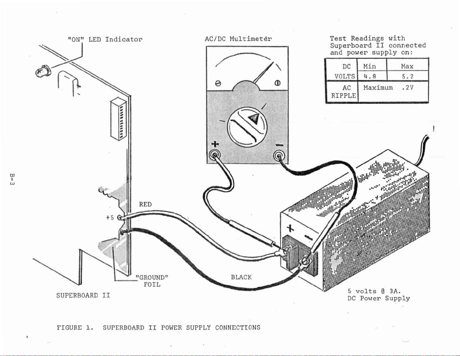
FIGURE
1.
+5
\J
II
SUPERBOARDIIPOWER
"GROUND"
FOIL
SUPPLY
BLACK
CONNECTIONS
5
DC
volts
Power
@
3A.
Supply
1.
Consult
The
power
supply
adequate~
2.
Choose
paper
computer
in
contact
3.
Observe
roughly,
4.
Make
5.
Connect
to
the
6.
Set
the
you
measure
or
0-10
==========================
SUPERBOARDIIONLY
==========================
a
clips,
sure
+
Figure
supply
(+
5\
work
or
that
flexed,
the
the
and
AC/DC
volts
1,
maximum
You'll
area
or
power
with
the
power
RED
-
terminals.
multimeter
5
volts
is
Superboard
MUST
ripple).
also
which
any
other
supply
the
foils
Superboard
bent,
supply
and
BLACK
accurately.
adequate.)
BE
need
or
a 5
is
could
to
II
power
volt
No
an
AC/DC
free
conductive
be
on
the
II
should
otherwise
is
not
wires
from
a
DC
@
3A
other
of
all
damaged
board.
abused.
plugged
voltage
(A
range
supply
(minimum)
supply
multimeter.
foreign
materials.
if
not
be
in.
the
Superboard
range
of
connections.
regulated
will
these
treated
to
0-
5)
be
matter,
The
come
II
let
0-6,
7
8.
9.
10.
11.
..
Next,
Superboard
Briefly
"ON"
and
Go
Again,
It
than
the
supply
computer.
Set
volts
Turn
This
If
hook-up.
you
turn
LED
glows.
check
back
must
everything
to
turn
be
4.8
indicates
required
delivering
the
multimete~·to
AC
(probably
on
the
represents
will
II,
on
your
Step
on
between
voltage
Turn
power
observe
and
the
If
power
1.
the
off
ripple
checks
the
power
not,
supply
power
4.8
that
or
more
the
the
supply
out,
the
power
supply
turn
supply
and
the
current
than
power
measure
lowest
and
and
proceed
"ON"
supply's
leads.
5.2
power
5.2
supply.
measure
must
LED
and
off
the
and
volts.
supply
capability.
volts
a
voltage
AC
range).
not
to
indicator
voltage
observe
supply
They
measure
exceed
may
the
the
may
A
reading
probably
of
AC
video
on
under
that
immediately
be
the
A
damage
about
voltage.
0.2
the
the
reversed.
DC
voltage.
less
lacks
power
the
0.5
volts
display
load.
AC.
B-4

VIDEO
DISPLAY
CONNECTION
to
lined
There
the
as
1.
are
Superboard
follows:
Preferred
cable
circuit
Model AC-3
cation.
video
2.
Connect
modulator"
television's
inexpensive
with
3.
Have
modified
special
CLOSED-CIRCUIT
three
to
TV
cable
the
your
a
standard
safety
VIDEO
different
II
and
method
the
high
video
12"
The
unit
is
supplied
which
antenna
and
computer.
to
accept
MONITOR
methods
Challenger
-
connect
impedance
monitor.
monitor
doubles
disconnected.
is,
allow
AC
precautions
which
computer
in
turn,
terminals.
you
transformer-operated
direct
CONNECTION
IP
the
(Hi-Z)
Ohio
as
to
video
which
of
attaching
computers.
supplied
Scientific
is
ideal
a
television
video
connected
RF
use
almost
entry.
will
computer
input
of
for
cable
to
Modulators
any
television
This
be
explained
a
video
These
a
offers
this
when
to
an
a
standard
television
requires
are
video
closed-
appli-
the
"RF
are
displ~.
out-
the
later.
1.
2.
3.
4.
5.
6.
Refer
the
is
assembly.
Connect
input
RCA-type
impedance
present,
the
Observe
the
a
Turn
Allow
filled
If
to
to
computer
part
of
manufacturer's
monitor
properly
on
the
necessary,
obtain
of
the
the
the
with
Figure
as
a
computer
other
the
or
video
phono
-
low
there
manufacturer's
has
grounded
computer
monitor
random
adjust
a
stable
2.
Attach
shown.
end
monitor.
jack
input.
impedance
may
instructions.
a
3-wire
3-wire
to
graphics
picture.
the
With
video/cassette
of
the
On
selector
be
two
power
grounded
AC
and
monitor.
warm-up.
characters,
the
VERTICAL
supplied
the
£able
The
other
or
outlet.
You
video
Superboard
recorder
to
the
high
AC-3
more
recommendations.
monitor
monitors,
switch
inputs.
plug,
should
and
HORIZONTAL
is
connect
see
alphabet,
cable
II
this
cable
impedance
has
a
high
sometimes
Consult
it
the
controls
to
cable
a
Hi-Z
If
to
screen
etc.
8-5
RF
MODULATOR/STANDARDTVCONNECTION
1.
Refer
included
2.
Connect
With
video/cassette
3.
Connect
~.
Connect
terminals
5.
Plug
6.
Turn
modulator
7.
At
and
(consult
8.
When
filled
is
HORIZONTAL
to
the
in
on
this
possibly
the
with
not
stable,
Figure
with
the
the
computer
Superboard
recorder
the
video
the
modulator
(consult
the
television
the
computer,
instructions).
point
you
adjust
modulator
television
random
adjust
controls
2.
Review
RF
II,
cable
modulator
will
the
instructions).
warms
graphics
as
the
modulator.
video
cable
this
cable
to
the
to
the
and
computer.
television,
have
to
television's
up
characters.
the
television's
needed.
manufacturer's
to
the
cable
assembly.
television's
is
RF
Modulator.
part
instructions).
and
modulator
select
the
fine
you
should
instructions
computer
of
a
antenna
proper
tuning
observe
If
the
VERTICAL
as
shown.
computer
(consult
TV
channe~
slightly
a
screen
picture
or
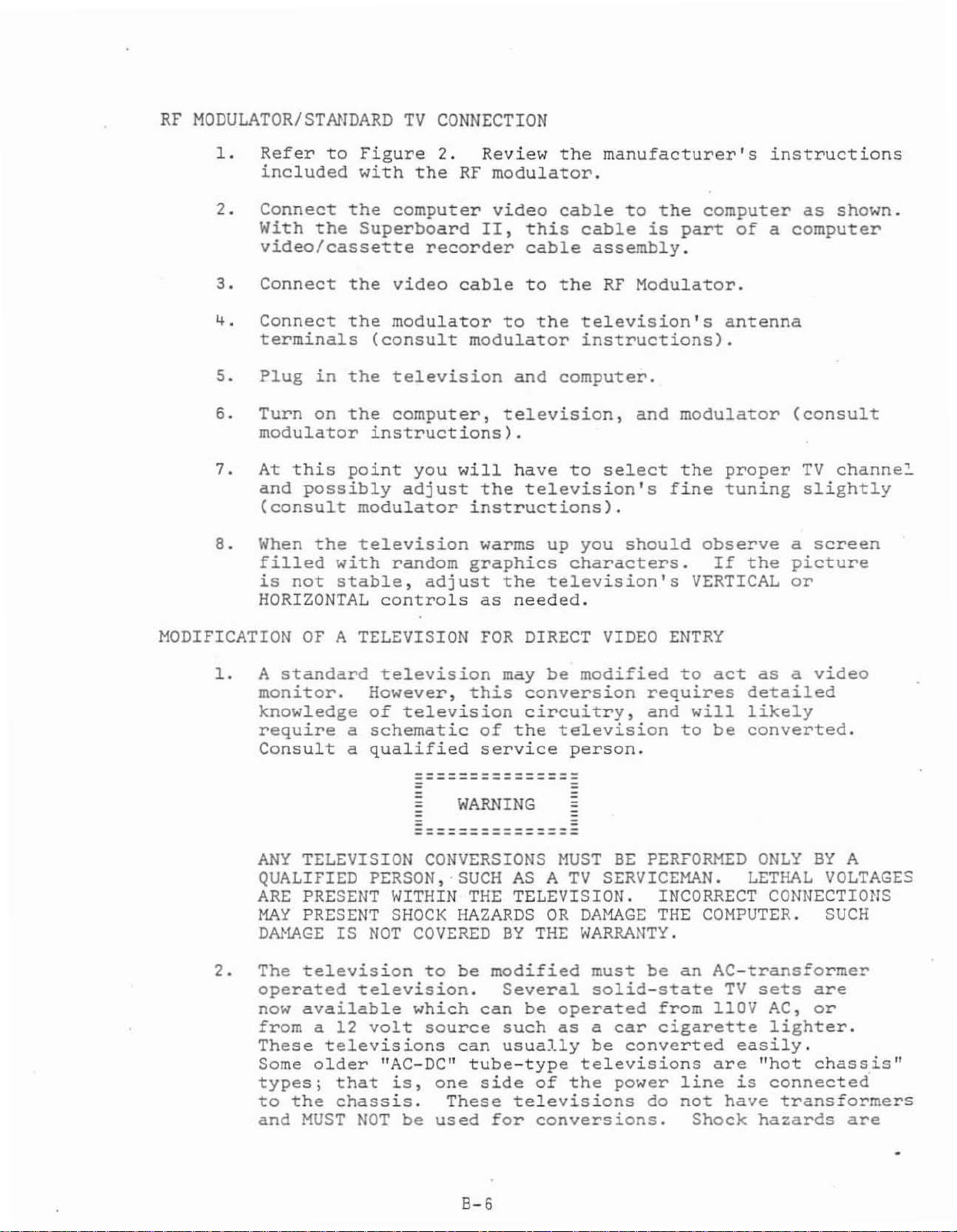
MODIFICATION
1.
A
standard
monitor.
knowledge
require
Consult
ANY
QUALIFIED
ARE
MAY
DAJ~GE
2.
The
operated
now
from
These
Some
types;
to
and
OF
A TELEVISION
However,
of
a
schematic
a
qualified
TELEVISION
PERSON,'SUCM
PRESENT
PRESENT
IS
NOT
television
television.
available
a 12
volt
televisions
older
that
the
chassis.
MUST
NOT
FOR
television
this
television
of
service
WARNING
- -
- -
---------------
---------------
CONVERSIONS
WITHIN
SHOCK
THE
HAZARDS
COVERED
to
be
modified
which
can
source
can
"AC-DClI
is,
tube-type
one
side
These
be
used
for
DIRECT
may
be
modified
conversion
circuitry,
the
television
person.
MUST
AS
A
TV
TELEVISION.
OR
DAMAGE
BY
THE
WARRANTY.
must
Several
be
such
usually
solid-state
operated
as
a
be
televisions
of
the
televisions
conversions.
VIDEO
ENTRY
to
act
requires
and
will
to
be
BE
PERFORMED
SERVICEMAN.
INCORRECT
THE
COMPUTER.
be
an
AC-transformer
car
from
cigarette
llOV
converted
are
power
do
line
not
Shock
as
a
detailed
likely
converted.
ONLY
LETHAL
CONNECTIONS
TV
sets
AC,
lighter.
easily.
"hot
is
connected
have
transformers
hazards
video
BY
A
VOLTAGES
SUCH
are
or
chassis"
are
8-6
3.
4.
5.
present,
televisions
Refer
More
if
12V
the
voltage.
can
this
conversion.
When
may
to
coils.
the
When
treated
Refer
to
characters
the
picture
DC
televisions,
television's
be
restored
adjustment
the
require
the
screen
time
the
to
and
are
that
Brightness
power
re-centering.
Refer
of
conversion.
television
as
a
that
the
section
is
supply
by
this
video
section
computer
suitable
per
line
"shrunken"
this
power
via
the
to
the
adjusting
adjustment
has
monitor
in
supply
will
TV
service
voltage
been
of
may
be
for
RF
this
can
can
this
manual.
be
slightly.
be
regulator
also
be
BRIGHTNESS
person
is
Equal
the
picture
to
modified,
and
connected
manual.
damaged.
modulator
displayed
On
accomplished
to
diminished,
CONTROL.
at
adjusted,
borders
tube
the
service
it
These
operation.
on
the
most
by
give
but
the
time
the
can
be
centering
person
may
then
to
the
screen
110V
adjusting
a
lower
this
Refer
of
picture
restored
at
be
computer.
AC/
B-7
.-
~~SPLAY
DEVICE
'"
m
~
L'wO
g
"
,
"
'"
~
~
STANDARD
RF
~\~,put
C..lot""I
terminals.
modulator
TELEVISION
to
antenna
in-
~
SUPERBOARD
I
II
CASSETTE
RECORDER
CABLES
VIDEO
I
To
video
MONITOR
Hi-Impedance
input.
VIDEO
APPROPRIATE
CABLE
TO
INPUT
~
CHALLENGER
_
IP
VIDEO
CABLE
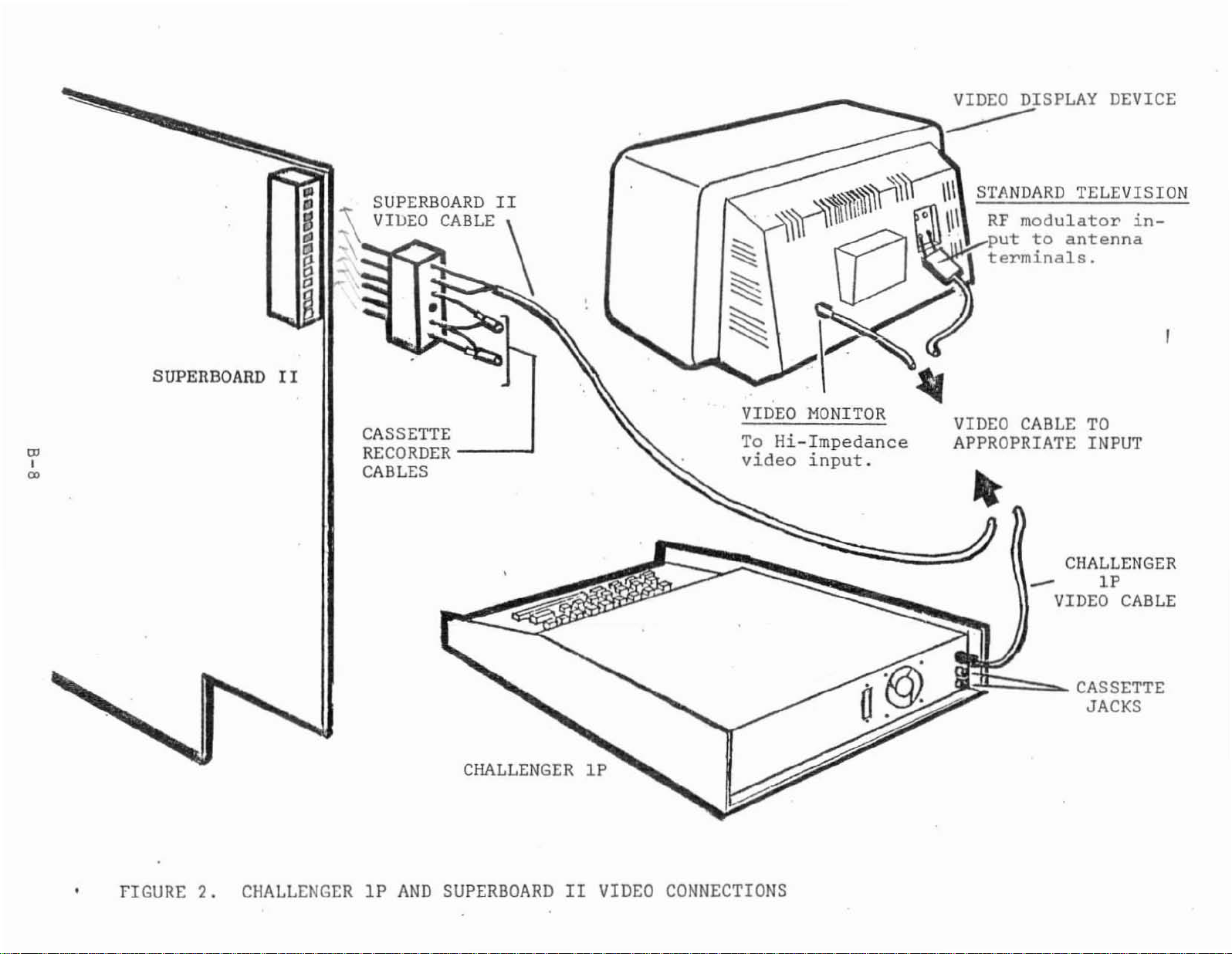
FIGURE
2.
CHALLENGERIPAND
CHALLENGER
SUPERBOARDIIVIDEO
IP
CONNECTIONS
~
1;;:11
CASSETTE
JACKS
DDDDDDDDDDDITJ
'"
"'
OJI!IJDDD
CONTROL-F'''!II
<>-
,
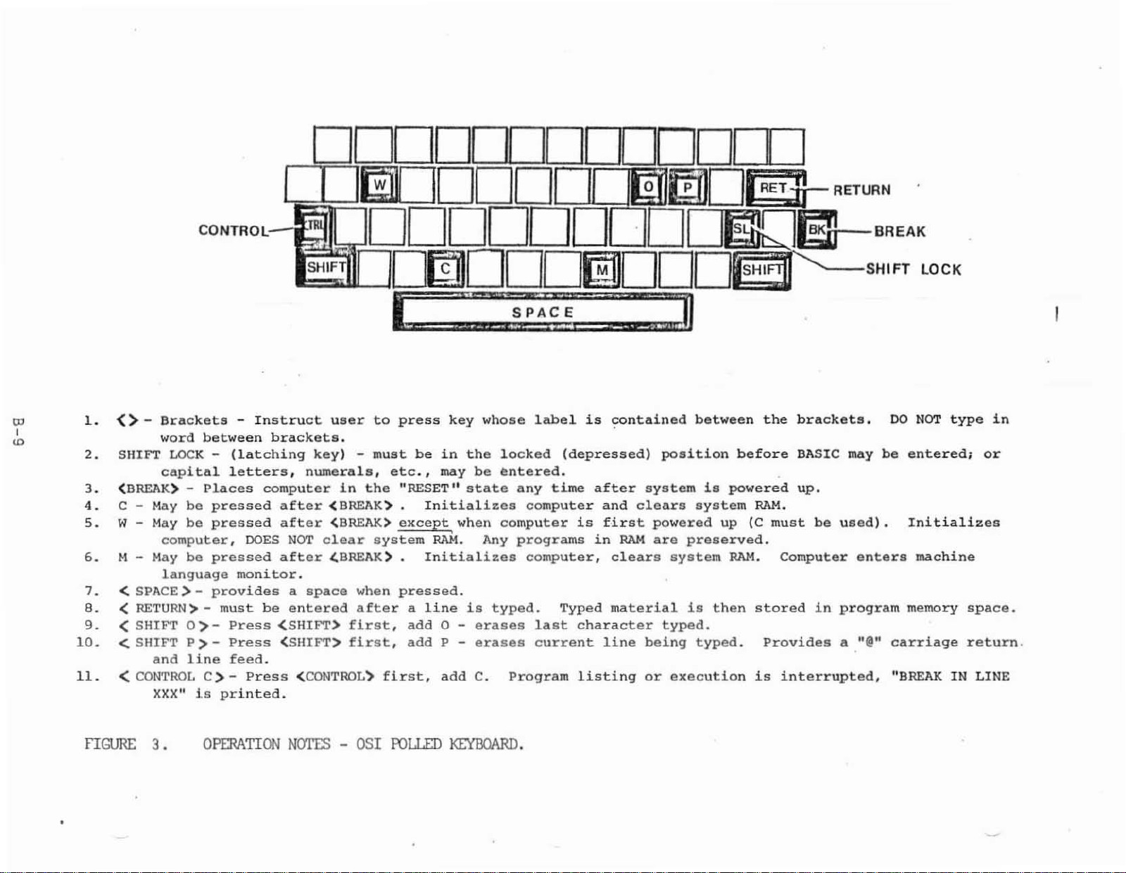
1.
SHIFT
2.
(BREAK) -
3.
e -
4.
5.
W-
M - May
6.
7.
< SPACE> -
8.
<SHIFT
9.
10.
< SHIFT P >-
11.
<
Brackets
word
LOCK-(latching
capital
May
be
May
be
computer,
be
language
< RETURN>-
0>-
and
line
CONTROL
XXX"
is
-
Instruct
between
letters.
Places
pressed
pressed
pressed
provides
must
C>-Press
printed.
computer
DOES
monitor.
be
Press
Press
feed.
brackets.
key)-must
numerals,
after
after
NOT
after
a
space
entered
(SHIFT)
(SHIFT>
<CONTROL')
'DDDDDD .
DmDDD~DDD~SH'FT
user
(BREAK>.
(BREAK>
clear
~BREAK).
1n
first,
first,
to
the
system
when
after
first,
t
press
etc.,
"RESET"
except
pressed.
a
add
add
::::
key
be
in
may
Initializes
when
RAM.
Initializes
line
0 P -
add
::::
whose
the
be
state
Any
is
typed.
erases
erases
C.
i:;
fE:
label
locked
entered.
any
time
computer
computer
programs
computer,
last
current
Program
is
(depressed)
after
is
in
Typed
character
listing
O·
D~En-BREAK
:::,
contained
system
and
clears
first
RAM
clears
material
line
being
or
~DI3--
RETURN
:::0
between
position
system
powered
are
preserved.
system
is
typed.
typed.
execution
is
up
then
the
before
powered
RAM.
(C
RAM.
stored
Provides
is
brackets.
BASIC
up.
must
be
Computer
in
interrupted,
may
used).
enters
program
a "@"
LOCK
DO
NOT
type
be
entered;
Initializes
machine
memory
carriage
"BREAK
space.
return,
IN
in
or
LINE
fIGURE
3.
OPERATION
N=
-
OS1
RlLLIJl
KIYIlCVIRIl.
INTRODUCTION
GETTING
YOUR
COMPUTER
"UP
AND
RUNNING"
These
in
the
stored
when
the
Several
words
as
<BREAK>
labeled
a
word
BEFORE
1.
2.
computer
in
the
computer
or
letters
and
with
contained
YOU
POWER-UP
Check
Make
connected
instructions
language
computer's
is
of
these
which
<,C>. The
the
word
between
...
that
certain
to
will
"BASIC".
memory,
turned
instructions
are
brackets
or
letter
the
all
power
that
the
computer
help
on.
bound
brackets
supply
your
you
This
and
for
by
brackets
indicate
must
video
properly.
get
your
·language
can
be
quickly
bringing
11.("
that
be
pressed.
letter-by-letter.
connections
monitor
computer
is
up
and
a
keyboard
Do
are
or
television
running
permanently
brought
BASIC
contain
n >",
key
not
type
See
correct.
up
such
~n
Figure
is
3.
GETTING
INTO
These
at
any
time,
as
indicated,
procedures,
1.
2.
3.
4.
BASIC
instructions
the
turn
wiring,
Turn
Turn
you
Press
in
Press
ask
on
on
will
<BREAK>.
the
<.C> .
"MEMORY
computer
off
etc.
the
computer.
the
television
observe
lower
SIZE?"
the
left
The
should
or
power
the
The
corner
screen
be
followed
television/monitor
to
or
screen
prompt
of
will
both
monitor.
and
filled
C/W/M?
the
screen.
scroll
very
review
After
with
or
up
closely.
does
not
all
a
short
random
D/C/W/M?
one
line
If,
respond
hook-up
warm-up
characters.
will
appear
and
B-10
 Loading...