

Ohio Medical Corporation MiniOX 1 Operating Manual
Medical Products • Medizinische Produkte • Productos Médicos • Produits Médicaux • Prodotti medici
MiniOX® 1
● Oxygen Analyzer
● Sauerstoff analysator ● Analizador de oxígeno
● Analyseur d’Oxygène ● Analizzatore d’ossigeno
Operating Manual
Customer Service: 1-847-855-0800
Repair: 1-847-855-0800
Fax: 1-608-222-6028
Gebrauch sanweisung
Kundendienst: 1-847-855-0800
Durchwahl 1-847-855-0800
Fax: 1-608-222-6028
Manual de Operacion
Servicio al Cliente 1-847-855-0800
Reparaciones: 1-847-855-0800
Fax: 1-608-222-6028
Manuel d’instructions
Service clientele: 1-847-855-0800
Reparations: 1-847-855-0800
Telefax: 1-608-222-6028
Manuale d’istruzioni
Assistenza al diente: 1-847-855-0800
Manutenzione: 1-847-855-0800
Fax: 1-608-222-6028
FEDERAL (U.S.) LAW RESTRICTS THIS PRODUCT TO SALE BY OR ON THE ORDER OF A PHYSICIAN
NACH US-AMERIKANISCHEM RECHT DARF DIESES PRODUKT NUR VON EINEM ARZT ODER AUF DESSENANORDNUNG HIN VERKAUFT WERDEN
LA LEY FEDERAL (EE.UU.) LIMITA LA VENTA DE ESTE PRODUCTO A LA ORDEN DE UN MÉDICO
LA LOI FEDERALE (DES ETATS-UNIS) N’AUTORISE LA VENTE DE CE PRODUIT QUE PAR OU SUR L’ORDRE
D’UNMEDECIN
AI SENSI DELLE LEGGI FEDERALI DEGLI STATI UNITI, IL PRESENTE PRODOTTO VA VENDUTO SOLO DIETROPRESCRIZIONE MEDICA
Manufactured by: Hergestellt von: Fabricado por: Fabrique par: Prodotto da:
Ohio Medical Corporation® | 1111 Lakeside Drive | Gurnee, IL 60031 USA
1-847-855-0800 | www.ohiomedical.com
P/N 711462 (Rev.3) 02/2016

This manual contains instructions in 5 languages. To nd the section written in your preferred
language, please turn to the colored divider indicated below:
Dieses Handbuch enthalt Anweisungen in 5 Sprachen. Zur leichten Aufndung sind die jeweiligen
Sprachenabschnitte mit folgenden Farben gekennzeichnet:
Este manual contiene instrucciones en 5 idiomas. Para encontrar la seccion escrita en el idioma de
su referencia, por favor elija el separador con el color indicado a continuacion:
Ce manuel contient des instructions en 5 langues. Pour trouver la section ecrite dans votre langue
préféréé, veuillez vous reporter au diviseur colorié indiqué ci-dessous :
Questo manuale contiene istruzioni in 5 lingue. Per trovare la sezione scritta nella lingua di preferenza, si prega di cercare it divisore in uno dei colori indicati qui sotto:
English: Buff
Deutsch: Grun
Espanol: Azul
Francais: Rouge
Italiano: Giallo
P/N 711462 (Rev.3) 02/2016

WARNING
THIS MANUAL MUST BE READ CAREFULLY PRIOR TO THE OPERATION OF THIS DEVICE. THIS
DEVICE WILL PERFORM AS DESIGNED ONLY IF USED IN ACCORDANCE WITH THE MANUFACTURER’S
INSTRUCTIONS. IMPROPER USE MAY CAUSE THE DEVICE TO FAIL TO PERFORM AS DESIGNED AND
MAY CAUSE INJURY TO THE PATIENT AND/OR HEALTHCARE PROFESSIONAL.
The warranties made by Ohio Medical Corporation® with respect to these products are voided if the products are
not installed, used and serviced in accordance with the instructions in this manual. Please protect yourself and
your patients by following them. We encourage our customers to write or call regarding this equipment prior to
use or for any additional information relative to use or repairs.
This product is not intended as a life-sustaining or life-supporting device.
Denition of Warnings and Cautions
WARNING
CAUTION
NOTE:
Statement citing a potential safety hazard and
possible injury to yourself or others.
Statement citing a possibility of damage to the
instrument or other property.
Advisory on instrument function.
P/N 711462 (Rev.3) 02/2016

Ohio Medical Corporation
®
Medical Instrument Warranty
This product is sold by Ohio MedicalTM under the warranties set forth in the following paragraphs. Such warranties
are extended only with respect to the purchase of this product directly from Ohio Medical or Ohio Medical’s
Authorized Dealers as new merchandise and are extended to the rst Buyer thereof, other than for purpose of
resale.
For a period of twelve (12) months from the date of original delivery to Buyer, to Buyer’s order, or to an Ohio
Medical Authorized Dealer, this product, other than its expendable parts, is warranted to be free from functional
defects in materials and workmanship and to conform to the description of the product contained in the operation
manual and accompanying labels and/or inserts, provided that the same is properly operated under conditions of
normal use, that regular periodic maintenance and service is performed and that replacements and repairs are
made in accordance with the instructions provided. This same warranty is made for a period of sixty (60) days
with respect to the expendable parts. The foregoing warranties shall not apply if the product has been repaired
other than by Ohio Medical or in accordance with written instructions provided by Ohio Medical, or altered by
anyone other than Ohio Medical, or if the product has been subject to abuse, misuse, negligence, or accident.
Ohio Medical’s sole and exclusive obligation and Buyer’s sole and exclusive remedy under the above warranties
is limited to repairing or replacing, free of charge, at Ohio Medical’s option, a product, which is telephonically
reported to the nearest Ohio Medical Regional Service Ofce and which, if so advised by Ohio Medical, is
thereafter returned with a statement of the observed deciency, not later than seven (7) days after the expiration
date of the applicable warranty,to the designated Ohio Medical Service Ofce during normal business hours,
transportation charges prepaid, and which, upon Ohio Medical’s examination, is found not to conform with
the above warranties. Ohio Medical shall not be otherwise liable for any damages including, but not limited to
incidental damages, consequential damages, or special damages.
There are no express or implied warranties which extend beyond the warranties herein above set forth. Ohio
Medical makes no warranty of merchantability or tness for a particular purpose with respect to the product or
parts thereof.
P/N 711462 (Rev.3) 02/2016

X® 1 Oxygen Analyzer Genearl WARNINGS and CAUTIONS
MiniO
General WARNINGS and CAUTIONS
WARNING
1. The MiniOX® 1 Oxygen Analyzer will perform to
specications only if it is used and serviced in
accordance with the manufacturer’s instructions. This
instrument is to be used only by qualied, trained
personnel who have carefully read the operating
manual and labels and who have observed the
information set forth. If this instrument does not
perform as described in this manual, the instrument
must not be used until the condition is rectied.
2. The MiniOX® 1 Oxygen Analyzer must be calibrated
prior to each use. A two point calibration check must
be performed weekly. (See Section 4, Operation) If
the instrument cannot be calibrated, the sensor must
be replaced. It the instrument still is unable to be
calibrated, the instrument must be serviced.
3. The oxygen sensor has a minimal response to
certain gases other than oxygen. Be aware of these
gases and their interference levels. See Section 3,
Performance Specications
water for at least 15 minutes, holding eyes open. Call a
physician.
6. Ensure a tight t exists between the sensor and the
tee adapter. Ohio Medical tee adapters are engineered
to t securely with Ohio Medical sensors. However,
the sensor retaining strap must be used to prevent
accidental separation of sensor and tee adapter.
7. Never use the MiniOX
atmosphere, such as occurs with ammable anesthetics.
Such use could result in ignition of atmosphere.
8. Use of devices generating or emitting electromagnetic
radiation near the MiniOX® 1 Oxygen Analyzer may
interfere with the proper operation of the product,
causing it to fail to perform as designed. Particularly,
the electromagnetic radiation from the interfering
device may cause the product to display incorrect/
erratic values or to stop operating. Special attention
should be paid to the patient if this occurs.
®
1 Oxygen Analyzer in combustible
4. The oxygen sensor is affected by changes in
barometric pressure. Refer to Section 4, Effects of
Pressure, for the effects of pressure
5. The sensor is a sealed unit containing a potassium
hydroxide electrolyte. If the sensor should develop a
leak, discard it immediately. Since the sensor contains
caustic material, it must be disposed of in accordance
with all applicable regulations in the country in which
it is used. Should contact occur with skin or clothing,
rinse area immediately with large quantities of water.
In case of eye contact, immediately ush eyes with
CAUTION
1. Remove internal battery if unit is to be non-operational
for extended periods of time.
2. Observe polarity when inserting a new battery.
Incorrect connection may cause damage to the
instrument.
3. The MiniOX® 1 Oxygen Analyzer must never be
immersed in any cleaning solution, autoclaved, or
exposed to temperatures greater than 70oC.
4. Use only genuine Ohio Medical Corporation
replacement parts when performing any maintenance
procedures provided in this manual. Failure to do so
may seriously impair the instrument’s performance.
Repair or alteration of the MiniOX® 1 Oxygen Analyzer
beyond the scope of these maintenance instructions
9. Never allow an excess length of cable near the patient’s
head or neck, as such could result in strangulation.
Secure excess cable to the bed rail or other suitable
object.
10. Never operate the MiniOX® 1 Oxygen Analyzer if it is
suspected that water or other liquids have entered into
the case. If this occurs, immediately turn the unit OFF
and contact your nearest Ohio Medical Corporation
Service Center for additional information.
FAILURE TO COMPLY WITH THESE WARNINGS CAN
RESULT IN SERIOUS INJURY OR DEATH OF THE
PATIENT.
or by anyone other than an authorized Ohio Medical
Corporation service person, could cause the product to
fail to perform as designed.
5. Improper mounting of the sensor in a breathing circuit
may result in inaccurate readings. The sensor MUST
be mounted with the deector pointing downward to
prevent moisture collection on the sensor membrane
(see Figure 4-1 in Section 4, Operation). Install the
sensor upstream from the humidier to minimize its
exposure to moisture.
6. Never use a MiniOX® 1 Oxygen Analyzer with a cable
that appears worn, cracked, or has damaged insulation
FAILURE TO COMPLY WITH THESE CAUTIONS CAN
RESULT IN INSTRUMENT DAMAGE.
APPLICABLE EUROPEAN STANDARDS
1. This device complies with Council Directive 93/42/EEC
(Medical Device Directive).
WC-1
P/N 711462 (Rev.3) 02/2016

MiniOX
®
1 Oxygen Analyzer Table of Contents
Table of Contents
Section 1
Introduction ........................................................................................ 1-1
WARNING ......................................................................................................................................1-1
WARNING ......................................................................................................................................1-1
®
Figure 1-1. MiniOX
1 Oxygen Analyzer .......................................................................................1-1
Section 2
Principal of Operation. ...................................................................... 2-1
Section 3
Specications ................................................................................... 3-1
Performance Specications . ........................................................................................................ 3-1
Interferent Gases and Vapors ......................................................................................................3-1
Instrument Replacement Parts ..................................................................................................... 3-1
Accessories .................................................................................................................................3-1
Servicing ....................................................................................................................................... 3-1
Electromagnetic Compatibility (EMC) ........................................................................................... 3-2
WARNING
Guidance and Manufacturer’s Declaration - Electromagnetic Emissions ...........................3-2
Guidance and Manufacturer’s Declaration - Electromagnetic Immunity .............................3-3
Recommended Separation Distances ................................................................................. 3-4
Section 4
Operation ........................................................................................... 4-1
Set-up Procedures ........................................................................................................................ 4-1
Calibration ....................................................................................................................................4-1
Two-point Linearity Check ............................................................................................................4-1
Instrument Operation .................................................................................................................... 4-1
Sensor Operation .........................................................................................................................4-2
Figure 4-1. Sensor Mounting in a Breathing Circuit ............................................................4-2
WARNING ............................................................................................................................4-2
WARNING ............................................................................................................................4-2
Retaining Strap Installation ........................................................................................................... 4-2
Figure 4-2. Retaining Strap Installation ...............................................................................4-2
TOC-1
P/N 711462 (Rev.3) 02/2016

MiniOX
®
1 Oxygen Analyzer Table of Contents
Effects of Pressure, Humidity, and Temperature ..........................................................................4-2
CAUTION ............................................................................................................................4-2
Effects of Pressure ..............................................................................................................4-2
CAUTION ............................................................................................................................4-3
Effects of Humidity ..............................................................................................................4-3
Effects of Temperature .........................................................................................................4-3
CAUTION .............................................................................................................................4-3
CAUTION .............................................................................................................................4-3
Section 5
Maintenance and Care ...................................................................... 5-1
WARNING ............................................................................................................................5-1
Battery Replacement ................................................................................................................... 5-1
Sensor Replacement .................................................................................................................... 5-1
Cleaning, Disinfection and Sterilization ........................................................................................5-1
CAUTION .............................................................................................................................5-1
Instrument ..................................................................................................................................... 5-1
Sensor and Cable ......................................................................................................................... 5-1
Sensor Deector, Retaining Strap and Tee Adapter .....................................................................5-2
Section 6
Technical Information ....................................................................... 6-1
Technical Description .................................................................................................................... 6-1
Figure 6-1. Block Diagram ........................................................................................................... 6-1
Appendix A
Home Care Kit ...................................................................................A-1
Installation ..................................................................................................................................... A-1
Figure A-1. MiniOX
®
1 Home Care Kit Installation ...................................................................... A-1
TOC-2
P/N 711462 (Rev.3) 02/2016
MiniOX
®
1 Oxygen Analyzer Section 1, Introduction
Section 1
Introduction
The MiniOX® 1 Oxygen Analyzer is designed to provide
continuous analyzing or spot checking of oxygen for:
• ventilators
• incubators
• emergency transports
• oxygen tents
• concentrators
• various other respiratory therapy uses
WARNING
This instrument is not equipped with an
alarm, and is therefore not for use in a lifesupport system. Failure to comply with this
warning can jeopardize patient well-being.
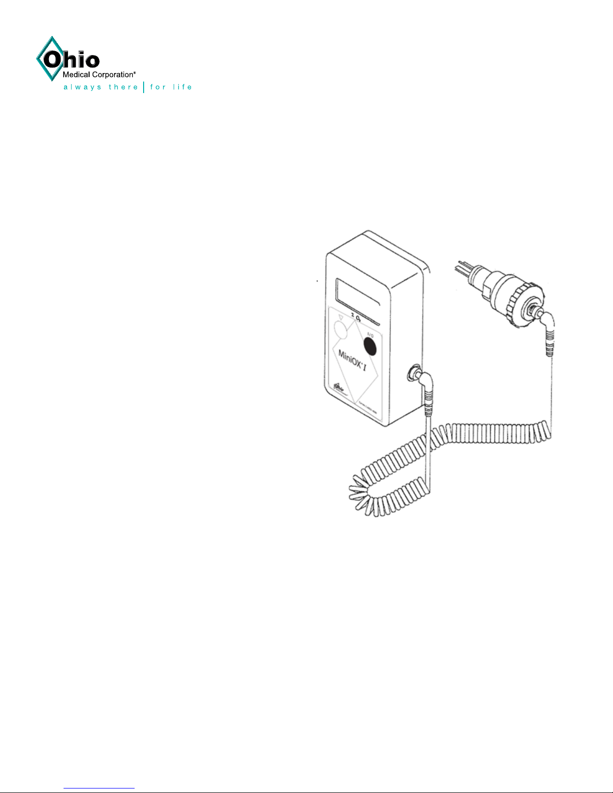
The MiniOX
®
1 Oxygen Analyzer (Figure 1-1):
• Operates by a single push of a button.
• Calibrates with the turn of a dial.
• Features an easy-to-read digital display
For sensor connection, a tee adapter is provided with
each instrument.
The galvanic oxygen sensor measures oxygen
concentrations from 0 to 100%. The sensor is
maintenance-free and will operate for one year in
normal medical use.
WARNING
Users must familiarize themselves with the
contents of this manual before using the
MiniOX
®
1 Oxygen Analyzer. Failure to do
so can cause misuse of the instrument, and
jeopardize patient well-being.
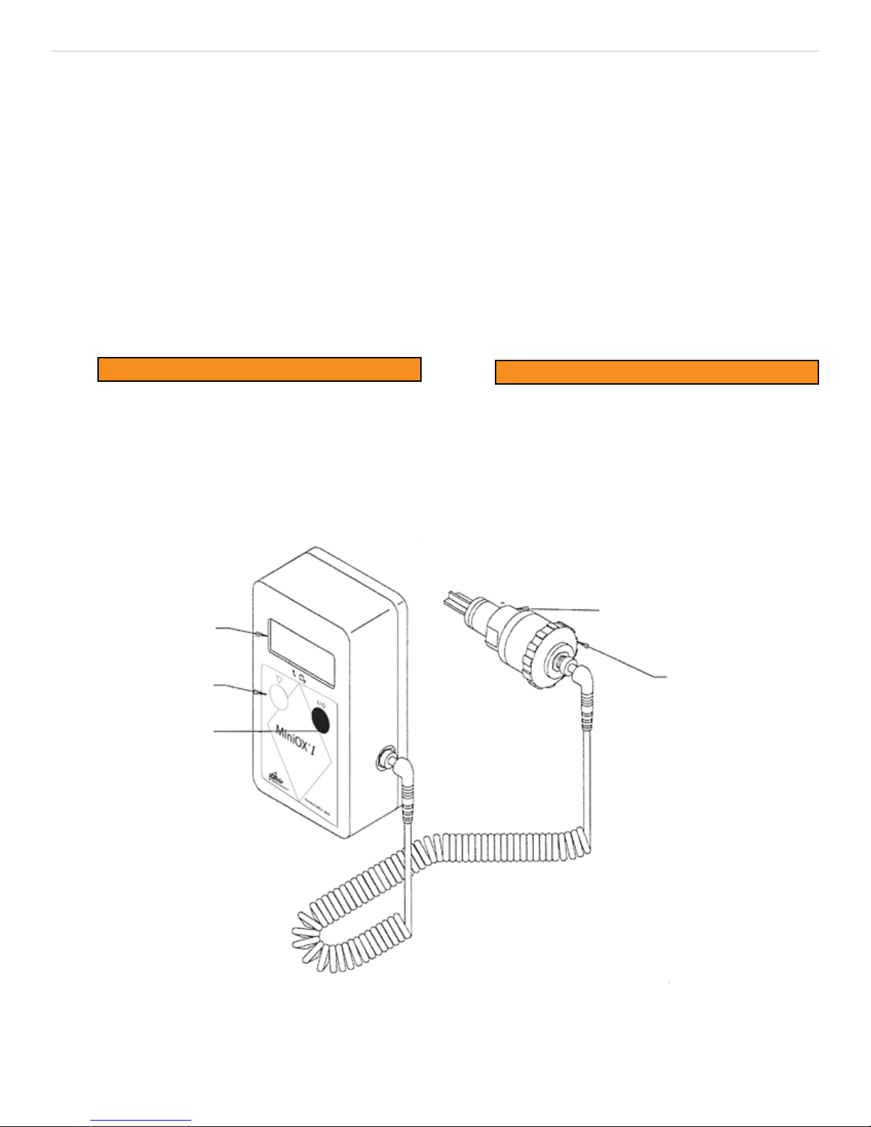
DIGITAL
DISPLAY
CALIBRATION
DIAL
ON/OFF
BUTTON
DEFLECTOR
SENSOR
1-1
Figure 1-1
MiniOX® 1 Oxygen Analyzer
P/N 711462 (Rev.3) 02/2016

MiniOX
®
1 Oxygen Analyzer Section 2, Principal of Operation
Section 2
Principal of Operation
Each MiniOX® 1 Oxygen Analyzer uses a galvanic
oxygen sensor which is long-lived and maintenancefree.
The sensor consists of two electrodes:
• a cathode
• an anode
The gold cathode is exposed to the atmosphere
through a uoropolymer membrane. The lead anode is
submersed in a potassium hydroxide solution.
When oxygen diffuses through the membrane, the
electrochemical reduction of oxygen on the cathode
and the corresponding oxidation of the anode
generate an electrical current. The current produced
is proportional to the partial pressure of oxygen in the
sample atmosphere. The resulting electrical current is
monitored, temperature compensated, and amplied to
drive the display .
The sensor is self-zeroing; when no oxygen is present
to be chemically reduced and oxidized, minimal current
is produced. Thus, zero percent oxygen is displayed.
2-1
P/N 711462 (Rev.3) 02/2016

MiniOX
®
1 Oxygen Analyzer Section3, Specications
Section 3
Specications
Performance Specications
Range 0-100% O
2
Display Resolution 0.1% O2 increments
Linearity
Accuracy
Low Battery Indicator
+2% of full scale
+2% of full scale
“LO BAT” appears on the
display
Warm-Up Time None required
Operating Temperature
Range
Storage Temperature range -20
o
0
to 40oC (32o to 104oF)
o
to 55oC (-4o to 131oF)
Humidity 0 to 95% RH
Power Requirements One 9-volt alkaline battery
Battery Life Approximately 1,400 hours
Dimensions
Instrument 4-5/8” x 2-1/2” x 1-1/2”
Sensor 1-15/16” OD x 1-7/8” long
Cable Length 10 Ft. (3m) fully extended
Sensor Type
Sensor Life
Galvanic fuel sensor 0-100%
O
2
Over one year in normal
medical conditions
Sensors, as shipped, can be
Shelf Life
stored for a maximum of 6
months without degradation
of life
Response
Time measured with
deector and
mounted in a
22 mm tee
adapter @
o
25
C
FLOW
RATE LI-
TERS/MIN.
80% OF
CHANGE
(SECONDS)
2 13 21
5 12 20
10 11 19
97% OF
CHANGE
(SECONDS)
Interferent Gases and Vapors
Interferent Gases and Vapors
INTERFERENT
% BY VOL-
UME (DRY
GAS)
INTERFERENT
EQUIVALENT
OF PERCENT O
Helium 80% <0.2%
Methoxyurane 4% <2.3%
Nitrogen 80% <0.2%
Nitrous Oxide 80% <0.8%
Instrument Replacement Parts
DESCRIPTION PART NUMBER
Case Screw 637408
Dovetail Mounting Bracket 474606
40x3/8” stainless stee screw (set
of 4)
450000
Accessories
ITEM PART NUMBER
Alkaline battery, 9-Volt 628817
Coiled Cable 472045
Deector 470687
Home Care Kit (see Appendix A) 474682
Mounting Bracket,Pole 474664
Mounting Bracket, wall 10023945
Operation/Maintenance Manual
CD
600700
Operation Manual (Printed) 711462
Oxygen Sensor 406931
Sensor Retaining Strap 634249
Tee Adapter 473021
Carrying Case 710462
Sleeve Adapter 474667
2
INTERFER-
ENT
%BY
VOLUME
(DRY GAS)
INTERFERENT EQUIVA-
LENT OF PERCENT O
Carbon Dioxide 12% <0.1%
Cyclopropane 50% <0.1%
Diethyl Ether 20% <1.5%
Enurane 4% <0.5%
Halothane 5% <0.9%
3-1
2
Inspection and Servicing SVC-101
Calibration SVC-102
Enclosure Replacement SVC-103
Circuit Board Replacement SVC-104
Button and Sensor Jack
Replacement
P/N 711462 (Rev.3) 02/2016
Servicing
SVC-105

MiniOX
®
1 Oxygen Analyzer Section 3, Specications
Electromagnetic Compatibility (EMC)
WARNING
Ensure that the specied electromagnetic environment and separation distances for the MiniOX® 1 Oxygen
Analyzer observed according to the tables below. Misuse may result in failure to perform as designed,
including incorrect/erratic readings.
Guidance and manufacturer’s declaration - electromagnetic emissions
The MiniO
MiniOX
X® 1 is intended for use in the electromagnetic environment specied below. The customer or the user of the
®
1 should ensure that it is used in such an environment.
Emissions test Compliance Electromagnetic environment - guidance
RF emissions
CISPR 11
RF emissions
CISPR 11
Harmonic emissions
IEC 61000-3-2
Group 1
Group B
Not applicable Not applicable
The MiniO
X® 1 uses RF energy only for its internal function.
Therefore, its RF emissions are very low and are not likely to
cause any interference in nearby electronic equipment.
The MiniO
X® 1 is suitable for use in all establishments
including domestic establishments and those directly
connected to the public low-voltage power supply network
that supplies buildings used for domestic purposes.
Voltage uctuations/icker
emissions
Not applicable Not applicable
IEC 61000-3-3
Guidance and manufacturer’s declaration - electromagnetic immunity
The MiniO
MiniOX
Electrostatic discharge
(ESD)
IEC 61000-4-2
Electrical fast transient/burst
IEC 61000-4-4
Surge
IEC 61000-4-5
X® 1 is intended for use in the electromagnetic environment specied below. The customer or the user of the
®
1 should ensure that it is used in such an environment.
Immunity test
IEC 60601
test level
+6kV contact
+8kV air
+2kV for power supply lines
+1kV for input/output lines
+1kV line(s) to line(s)
+2kV line(s) to earth
Compliance level
+6kV contact
+8kV air
Not Applicable Not Applicable
Not Applicable Not Applicable
Electromagnetic environment -
guidance
Floors should be wood, concrete
or ceramic tile. If oors are covered
with synthetic material, the relative
humidity should be at least 30%
Voltage dips, short
interruptions and voltage
variations on power supply
Not Applicable Not Applicable Not Applicable
input lines
IEC 61000-4-11
Power frequency (50/60 Hz)
magnetic eld
IEC 61000-4-8
NOTE: U
T is the a.c. mains voltage prior to application of the test level.
3 A/m 3 A/m
Power frequency magnetic elds should
be at levels characteristic of a typical
location in a typical commercial or
hospital environment.
3-2
P/N 711462 (Rev.3) 02/2016
MiniOX
®
The MiniO
MiniOX
Immunity
1 Oxygen Analyzer Section 3, Specications
Guidance and manufacturer’s declaration - electromagnetic immunity
X® 1 is intended for use in the electromagnetic environment specied below. The customer or the user of the
®
1 should ensure that it is used in such an environment.
Test
IEC 60601
test level
Compliance
Level
Electromagnetic environment -
guidance
Portable and mobile RF communications equipment should
be used no closer to any part of the MiniOX
®
1, including
cables, than the recommended separation distance
calculated from the equation applicable to the frequency of
the transmitter.
Recommended separation distance
Conducted RF
IEC 61000-4-6
3Vrms
150 kHz to 80 MHz
0.4 Vrms
d = 8.8 SP
d= 1.2 SP 80 MHz to 800 MHz
Radiated RF
IEC 61000-4-3
20V/m
80 MHz to 2.5 GHz
3V/m
d = 2.3 SP 800 MHz to 2.5 GHz
where P is the maximum output power rating of the
transmitter in watts (W) according to the transmitter
manufacturer and d is the recommended separation
distance in metres (m).
Field strengths from xed RF transmitters, as determined
by an electromagnetic site survey,a should be less than the
compliance level in each frequency range.b
Interference may occur in the vicinity of equipment marked
with the following symbol:
NOTE 1 At 80 MHz and 800 MHz, the higher frequency range applies
NOTE 2 These guidelines may not apply in all situations. Electromagnetic propagation is affected by absorption and
reection from structures, objects and people.
a. Field strengths from xed transmitters, such as base stations for radio (cellular/cordless) telephones and land
mobile radios, amateur radio, AM and FM radio broadcast and TV broadcast cannot be predicted theoretically with
accuracy. To assess the electromagnetic environment due to xed RF transmitters, an electromagnetic site survey
should be considered. If the measured eld strength in the location in which the MiniO
applicable RF compliance level above, the MiniO
X® 1 should be observed to verify normal operation. If abnormal
performance is observed, additional measures may be necessary, such as reorienting or relocating the MiniO
X® 1 is used exceeds the
X® 1.
b. Over the frequency range 150 kHz to 80 MHz, induced voltages across the sensor cable should be less than 0.4
Vrms, and, over the frequency range 80 MHz to 2.5 GHz, eld strengths should be less than 3 V/m.
3-3
P/N 711462 (Rev.3) 02/2016

MiniOX
®
1 Oxygen Analyzer Section 3, Specications
Recommended separation distances between portable and mobile RF communications equipment
and the MiniOX® 1
The MiniO
The customer or the user of the MiniOX
X® 1 is intended for use in an electromagnetic environment in which radiated RF disturbances are controlled.
®
1 can help prevent electromagnetic interference by maintaining a minimum
distance between portable and mobile RF communications equipment (transmitters) and the MiniOX
ed below, according to the maximum output power of the communications equipment.
Rated maximum output
power of transmitter
(W)
150 kHz to 80 MHz
Separation distance according to frequency of transmitter
(m)
80 MHz to 800 MHz
d = 8.8 SP
d = 1.2 SP
800 MHz to 2.5 GHz
0.01 0.88 0.12 0.23
0.1 2.8 0.38 0.73
1 8.8 1.2 2.3
10 28 3.8 7.3
100 88 12 23
®
1 as recommend-
d = 2.3 SP
3-4
P/N 711462 (Rev.3) 02/2016

MiniOX
®
1 Oxygen Analyzer Section 4, Operation
Section 4
Operation
Set-up Procedures
1. Remove the contents from the shipping carton and
verify that you have one each of the following items:
®
• MiniOX
• 9-Volt Alkaline battery
• Oxygen Sensorand Deector in Sealed Package
• 10’ Coiled Cable with twist collar
• Sensor Retaining Strap
• MiniOX
• Tee Adapter
2. Remove the sensor form the sealed package and
attach it to the coiled cable.
• Firmly press the connector until it snaps into
place; tighten the twist collar.
• Insert the opposite end of the coiled cable into
the jack on the side panel of the instrument;
tighten the twist collar.
3. Remove the deector from the package.
• Insert the gasket into the open end of the
deector, ensuring that the gasket is properly
seated within the deector.
• Gently screw the deector onto the sensor.
For monitoring in a breathing circuit, see
gure 4-1, installing the sensor in a breathing
circuit.
1 Oxygen Analyzer
®
1 Operating/Maintenance CD
2. Place the sensor in a stream of air with a known
oxygen concentration or in room air,.
3. Wait for a least one minute, or until the reading has
stabilized.
4. If the reading on the display is other than the known
oxygen concentration, adjust the reading using
the calibration dial. Turn clockwise to increase
the reading, or counter clockwise to decrease the
reading.
5. If the reading cannot be adjusted to the known
concentration value, the sensor or instrument is
malfunctioning and must be serviced.
Two-Point Linearity Check
The purpose of a two-point check is to determine the
linearity of the sensor. Serious deviation from linearity
( + 2%) indicates the sensor is nearing end-of-life. To
perform a two-point linearity check:
1. Place the sensor in a stream of a known oxygen
concentration between 90-100% until the reading
stabilizes.
2. Calibrate to match this concentration.
3. After calibration, measure room air; the reading
should be 20.8% +2%. (A +2% linearity variation is
allowed for differences due to the method of sample
introduction, and the precision of initial setting.) If
the variation is greater than 2%, repeat the two-point
linearity check. If the variation remains greater then
2%, replace the sensor.
4. Attach the coiled cable to the instrument in the same
manner.
5. Remove the four screws holding the back panel in
place.
6. Install the battery.
7. Replace the back panel and screws.
8. After installing the sensor, allow to equilibrate prior
to calibration.
9. Proceed to Calibration procedures.
Calibration
The best method to calibrate the MiniOX® 1 Oxygen
Analyzer is with 100% oxygen. Calibrating with oxygen
concentrations less than 100% or with room air is less
desirable, but still acceptable.
1. Press the green I/0 button on the front panel to turn
on the instrument.
4-1
Instrument Operation
The MiniOX® 1 Oxygen Analyzer has a low battery
indicator. When the Low Battery indicator is activated,
LO BAT appears on the top left of the display. The
instrument functions normally for approximately eight
hours; however, replace the battery as soon as
possible.
If the sensor becomes disconnected while the
instrument is in use, the instrument displays between
-0.1 and +0.2.
The instrument is designed to read in percent from 0 to
100%; however, if incorrectly calibrated, it displays up to
199.
To maximize battery life, turn OFF the MiniOX® 1
Oxygen Analyzer when not in use.
P/N 711462 (Rev.3) 02/2016
MiniOX
®
1 Oxygen Analyzer Section 4, Operation
Sensor Operation
The oxygen sensor has a minimal response to certain
gases other than oxygen. Be aware of these gases
and their interference levels. See Section 3, Interferent
Gases and Vapors.
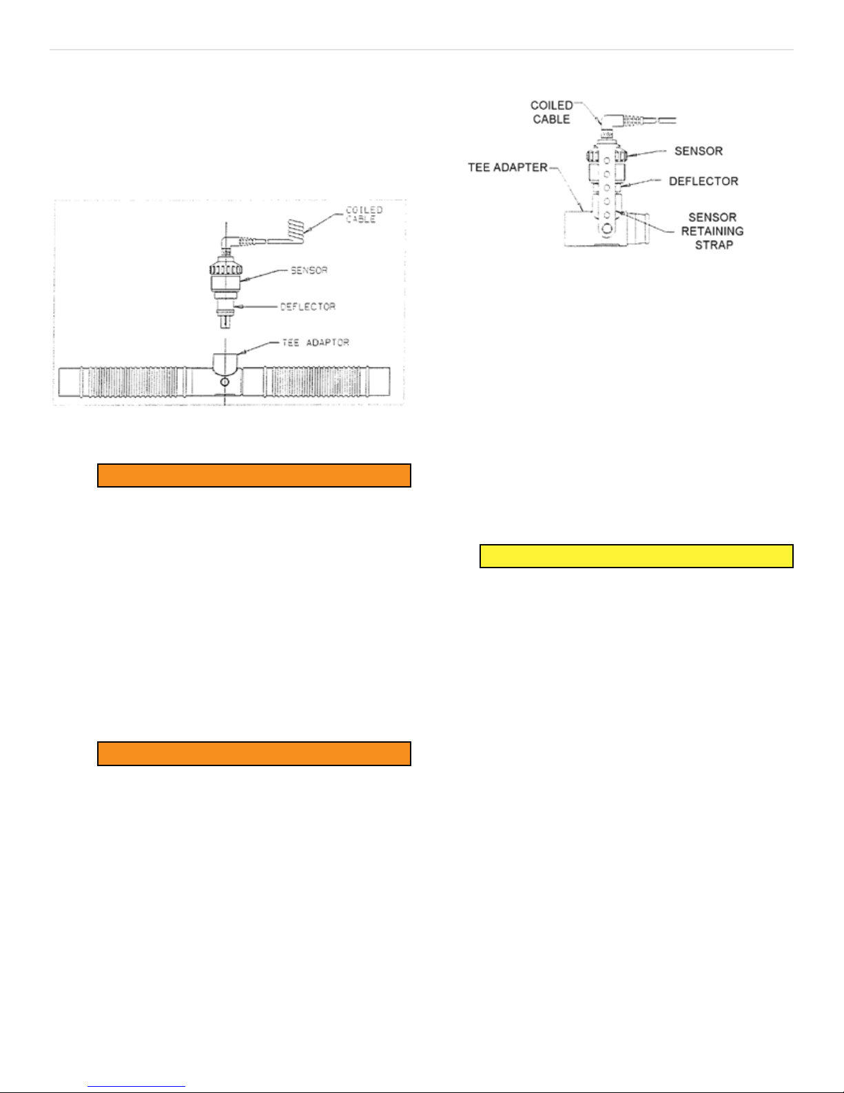
2. Firmly insert the sensor into the tee adapter with the
deector pointing downward; ensure a tight t exists.
Figure 4-2
Retaining Strap Installation
3. Install one end of the strap over a post on the tee
adapter.
4. Loop the strap around the sensor, inserting the strap
center hole over the sensor cable jack.
5. Install the remaining strap end over the other tee
adapter post.
Figure 4-1
Sensor Mounting in a Breathing Circuit.
WARNING
The sensor is a sealed unit containing a
potassium hydroxide electrolyte. If the
sensor should develop a leak, discard it
immediately. Should contact occur with skin
or clothing, rinse area with large quantities
of water. In case of eye contact, immediately
ush eyes with water for at least 15 minutes,
holding eyes open. Call a physician.
When using the sensor in a breathing circuit, mount
the sensor with the deector pointing downward (see
Figure 4-1). This prevents moisture from draining on to
the sensor membrane (see Section 5, Maintenance and
Care).
WARNING
Ensure a tight t exists between the sensor
and the tee adapter. Ohio Medical tee
adapters are engineered to t securely with
Ohio Medical sensors. However, the sensor
retaining strap must be used to prevent
accidental separation of the sensor and tee
adapter.
6. Attach the coiled cable to the sensor.
7. Tighten the twist collar.
The sensor is now secured in place.
Effects of Pressure, Humidity, and
Temperature
CAUTION
To ensure accurate and reliable oxygen
analysis, a thorough understanding of
the effects of pressure, humidity, and
temperature on the sensor is necessary.
Effects of Pressure
The sensor actually senses partial pressure of oxygen,
not percentage. Changes in barometric pressure
changes the reading, even if the percent of oxygen in
the sample remains constant.
Partial pressure of oxygen (PO2) equals the percent
of oxygen (%,O2) times (x) the pressure at which the
sample is measured (mmHg-mercury):
PO2 = (%O2) (mmHg)
For example:
Retaining Strap Installation
To install the retaining strap:
1. Remove the coiled cable from the sensor (Figure
4-2).
At sea level the pressure equals 760 mmHg and
dry air contains 21 % O2. Therefore;
PO2 = (21%) (760 mmHg)
PO2 = 160 mmHg
4-2
P/N 711462 (Rev.3) 02/2016

MiniOX
®
1 Oxygen Analyzer Section 4, Operation
If the instrument is calibrated to read 21% at 160 mmHg
partial pressure, then take the instrument to an area
above sea level, where the atmospheric pressure is 700
mmHg; a lower reading is found due to a lower partial
pressure.
PO2 = (21%) (700 mmHg)
PO2 = 147 mmHg
The percent reading on the instrument is derived by the
following formula:
PO2 Actual = X, 147 mmHg = X or,
PO2 Sea level 21% 167 mmHg 21%
(21%) (147 mmHg) = 19.3%
X =
(160 mmHg)
Therefore, to eliminate error caused by pressure
changes, the instrument must be calibrated at the
pressure it is to be used.
CAUTION
Do not expose the sensor to pressure
outside the range of 600 to 900 mmHg (23.62
to 35.43 inches Hg.) as this can produce
instrument errors.
If moisture condenses on the diffusion membrane of
the sensor face, the oxygen path is physically blocked
and a lower oxygen concentration is indicated. This is
typical of all oxygen gas sensors, and is more likely to
occur when the sensor is located downstream from a
humidier.
Mount the sensor, when used in a breathing circuit, so
the deector points downward to prevent moisture from
draining onto the diffusion membrane (see Figure 4-1).
Also, mount the sensor, when possible, upstream of the
humidier.
Effects of Temperature
Each MiniOX® 1 sensor is desensitized to temperature
changes using a thermistor (temperature variable
resistor) located within the sensor. Variations in the
sensor reading due to temperature changes, are less
than 3% when used or calibrated between 0 to 40
degrees centigrade. By using the instrument close to the
temperature at which it is calibrated, variations can be
minimized.
Operating Temperature Range:
0o to 40oC (32o to 104oF)
Effects of Humidity
The presence of humidity in an oxygen sample
decreases the actual concentration of oxygen. Humidity
in a sample has the same effects as diluting the sample
with another gas.
For example:
If 100% oxygen is saturated with 100% humidity,
the actual concentration of oxygen drops from
100% to 96-97%. The instrument indicates this
drop in concentration.
CAUTION
Do not use instrument outside operating
temperature range.
CAUTION
Do not handle the sensor more than
necessary during calibration or use. Body
heat can cause the sensor’s thermistor to
change disproportional to the change in gas
sample temperature at the sensing electrode.
This can produce some error, until thermal
equilibrium is restored.
4-3
P/N 711462 (Rev.3) 02/2016

MiniOX
®
1 Oxygen Analyzer Secttion 5, Maintenance and Care
Section 5
Maintenance and Care
WARNING
Use only genuine Ohio Medical Corporation
replacement parts when performing any
maintenance procedures included in this
manual. Failure to do so may seriously
impair the analyzer’s performance. Repair or
alteration of the MiniOX® 1 Oxygen Analyzer
beyond the scope of the maintenance
instructions or by anyone other than an
authorized Ohio Medical Corporation service
person could cause the product to fail to
perform as designed.
Battery Replacement
The MiniOX® 1 Oxygen Analyzer requires one 9-volt
alkaline battery. To replace the battery:
1. Verify the instrument is turned OFF. If it is ON,
press the green I/O button on the front panel to
turn the instrument OFF.
2. Remove 4 screws from cover to expose sensor.
3. Remove the old sensor from the coiled cable.
4. Attach a new sensor to the coiled cable. Tighten the
twist collar.
5. Recalibrate the instrument. (See Section 4,
Calibration)
Cleaning, Disinfection and Sterilization
CAUTION
Never autoclave, immerse, or expose the
MiniOX® 1 Oxygen Analyzer (including
sensor) to high temperatures (>700C). Never
expose the device to pressure, irradiation,
vacuum, steam, or chemicals (other than
alcohol or mild cleaning agents).
Clean the instrument and sensor by wiping with a
cloth lightly dampened with Isopropyl Alcohol or mild
detergent. Make sure that no moisture seeps into the
instrument case or cable jack port.
Instrument
2. Remove the back panel, which is held in place
by four small screws.
3. Remove and discard the old battery; replace
with a new battery.
4. Replace the back panel and reinstall the
screws.
5. Recalibrate the instrument. (See Section 4,
Calibration)
Sensor Replacement
To ensure safe and effective use of your device, the
sensor must be replaced with a MiniOX® sensor as
this sensor is manufactured for this instrument. Use of
other types of sensors has not been tested and is not
endorsed by Ohio Medical Corporation. Use of other
sensor types will void your warranty.
There are no serviceable parts in the sensor or cable
assemblies; the entire unit must be replaced.
When the MiniOX® 1 Oxygen Analyzer is unable to be
calibrated, or gives erratic readings, the sensor must be
replaced. To replace the sensor:
1. Verify the instrument is turned OFF. If it is ON, press
the green I/O button on the front panel to turn the
instrument OFF.
When cleaning or disinfecting the instrument, care must
be taken to prevent entry of solutions into the instrument
case.
Cleaning
The external surfaces of the unit may be cleaned
by wiping them with a cloth moistened with a mild
detergent solution.
Disinfection
The external surfaces of the unit may be disinfected
by wiping them with a cloth moistened with ethanol
or Cidex. The instrument is not designed to withstand
the conditions imposed by steam, ethylene oxide or
radiation sterilization.
Sensor and Cable
Cleaning
The external surfaces of the oxygen sensor and of
the cable may be cleaned by wiping them with a cloth
moistened with a mild detergent solution.
Disinfection
The external surfaces of the oxygen sensor housing and
of the cable may be disinfected by wiping them with a
5-1
P/N 711462 (Rev.3) 02/2016

MiniOX
®
1 Oxygen Analyzer Section 5, Maintenance and Care
cloth moistened with ethanol or Cidex. The instrument
is not designed to withstand the conditions imposed by
steam, ethylene oxide or radiation sterilization.
Sensor Deector, Retaining Strap and Tee
Adapter
The sensor deector, retaining strap and tee adapter
may be cleaned by wiping them with a cloth moistened
with a mild detergent solution. The parts must be
thoroughly dry before they are used.
Disinfection
The sensor deector, retaining strap and tee adapter
may be disinfected by washing them with ethanol or
Cidex (per manufacturer’s instructions). The parts must
be thoroughly dry before they are used.
Sterilization
The sensor deector, retaining strap and tee adapter
may be sterilized using Cidex (per manufacturer’s
instructions), steam or ethylene oxide. Due to the
varying conditions imposed on materials during
sterilization, it is not possible to determine the exact
number of times sterilization processes can be carried
out. Therefore, the operator must carefully examine the
sensor deector, retaining strap and tee adapter after
sterilization and prior to use to verify that the items are
t for use. The operator must verify that the items are
free from tears and cracks and that the items have not
undergone any material changes that may compromise
their tness for use (e.g., brittleness and dimensional
changes). The operator must also examine the items
to verify that the items are free of chemical residuals
resulting from the sterilization process.
Because of the variability of cleaning, disinfection
and sterilization processes, Ohio Medical Corporation
cannot provide specic sterilization instructions, nor can
the sterility of an item be ensured
5-2
P/N 711462 (Rev.3) 02/2016
MiniOX
®
1 Oxygen Analyzer Secttion 6, Tehnical Information
Section 6
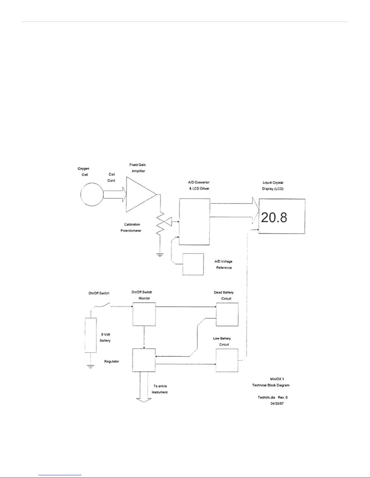
Technical Information
Technical Description
The MiniOX® 1 Oxygen Analyzer is designed to provide
continuous analyzing or spot checking of oxygen for
ventilators, incubators, emergency transports, and
various other respiratory therapy uses.
Each MiniOX® 1 Oxygen Analyzer instrument uses an
external Galvanic oxygen sensor with its coiled cord
to provide an analog voltage signal proportional to the
percentage of oxygen being sensed.
The oxygen cell provides an eight (8) to seventeen (17)
millivolt signal (at 20.8% oxygen), which is amplied
by a xed gain instrumentation amplier. The output of
this amplier is fed into a potentiometer which allows
for manual control by the operator, of the signal fed to
the Analog to Digital/Liquid Crystal Driver section. The
operator will manually adjust the control in a known
oxygen concentration so the displayed value matches
the ambient oxygen concentration.
Supervisory circuits are present to provide a stable
voltage reference for the A/D circuitry, provide battery
level monitoring, regulators to keep the DC supply
voltages on the devices constant and an ON/OFF switch
press monitor circuit.
Figure 6-1
Block Diagram
6-1
P/N 711462 (Rev.3) 02/2016
MiniOX
®
1 Oxygen Analyzer Appendix A, Home Care Kit
Appendix A
Home Care Kit
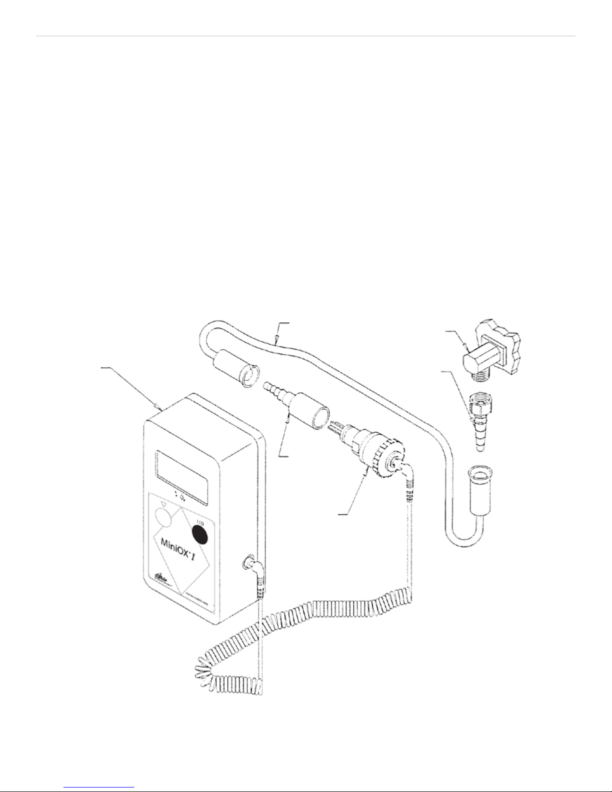
Installation
(Figure A-l)
1. Remove the humidier from the oxygen
concentrator.
2. Thread the universal nipple adapter onto the
oxygen concentrator.
3. Place the sleeve adapter on the oxygen sensor.
4. Using the standard oxygen tubing provided,
connect the oxygen sensor to the nipple adapter
on the oxygen concentrator.
5. Proceed to analyze the oxygen concentration.
(Ensure the ow rate does not exceed four liters-
per-minute).
6. When the oxygen analysis is complete, remove
the sampling apparatus and reinstall the
humidier.
OXYGEN
TUBING
OXYGEN
CONCENTRATOR
OXYGEN
ANALYZER
UNIVERSAL
NIPPLE
ADAPTER
SLEEVE
ADAPTER
OXYGEN
SENSOR
A-1
MiniOX
Figure A-1
®
1 Home Care Kit Installation
P/N 711462 (Rev.3) 02/2016

P/N 711462 (Rev.3) 02/2016

WARNUNG
THIS MANUAL MUST BE READ CAREFULLY PRIOR TO THE OPERATION OF THIS DEVICE. THIS
DEVICE WILL PERFORM AS DESIGNED ONLY IF USED IN ACCORDANCE WITH THE MANUFACTURER’S
INSTRUCTIONS. IMPROPER USE MAY CAUSE THE DEVICE TO FAIL TO PERFORM AS DESIGNED AND
MAY CAUSE INJURY TO THE PATIENT AND/OR HEALTHCARE PROFESSIONAL.
The warranties made by Ohio Medical Corporation® with respect to these products are voided if the products are
not installed, used and serviced in accordance with the instructions in this manual. Please protect yourself and
your patients by following them. We encourage our customers to write or call regarding this equipment prior to
use or for any additional information relative to use or repairs.
This product is not intended as a life-sustaining or life-supporting device.
Beschreibung der Warn- und Sicherheitshinweise
WARNUNG
ACHTUNG
HINWEIS
Weist auf potentielle Gefahrensituationen hin, durch die
der Bediener sowie andere verletzt werden können.
Weist auf Situationen hin, durch die das Gerät oder
andere Gegenstande beschädigt werden können.
Hinweis zum Betrieb des Gerätes.
P/N 711462 (Rev.3) 02/2016

Ohio Medical Corporation
Garantie für medizinische Geräte
This product is sold by Ohio MedicalTM under the warranties set forth in the following paragraphs. Such warranties
are extended only with respect to the purchase of this product directly from Ohio Medical or Ohio Medical’s
Authorized Dealers as new merchandise and are extended to the rst Buyer thereof, other than for purpose of
resale.
For a period of twelve (12) months from the date of original delivery to Buyer, to Buyer’s order, or to an Ohio
Medical Authorized Dealer, this product, other than its expendable parts, is warranted to be free from functional
defects in materials and workmanship and to conform to the description of the product contained in the operation
manual and accompanying labels and/or inserts, provided that the same is properly operated under conditions of
normal use, that regular periodic maintenance and service is performed and that replacements and repairs are
made in accordance with the instructions provided. This same warranty is made for a period of sixty (60) days
with respect to the expendable parts. The foregoing warranties shall not apply if the product has been repaired
other than by Ohio Medical or in accordance with written instructions provided by Ohio Medical, or altered by
anyone other than Ohio Medical, or if the product has been subject to abuse, misuse, negligence, or accident.
Ohio Medical’s sole and exclusive obligation and Buyer’s sole and exclusive remedy under the above warranties
is limited to repairing or replacing, free of charge, at Ohio Medical’s option, a product, which is telephonically
reported to the nearest Ohio Medical Regional Service Ofce and which, if so advised by Ohio Medical, is
thereafter returned with a statement of the observed deciency, not later than seven (7) days after the expiration
date of the applicable warranty,to the designated Ohio Medical Service Ofce during normal business hours,
transportation charges prepaid, and which, upon Ohio Medical’s examination, is found not to conform with
the above warranties. Ohio Medical shall not be otherwise liable for any damages including, but not limited to
incidental damages, consequential damages, or special damages.
There are no express or implied warranties which extend beyond the warranties herein above set forth. Ohio
Medical makes no warranty of merchantability or tness for a particular purpose with respect to the product or
parts thereof.
P/N 711462 (Rev.3) 02/2016

MiniOX® 1 Sauerstoff analysator Allgemeine WARN- und SICHERHEITSHINWEISE
Allgemeine WARN- und SICHERHEITSHINWEISE
WARNHINWEIS
1. Der MiniOX® 1 Sauerstoff analysator funktioniert nur dann
spezikationsgemäß, wenn dieser der Anleitung des Herstellers entsprechend eingesetzt und gewartet wird. Dieses
Gerät darf nur von qualiziertem, geschultem Personal
bedient werden, das das Betriebshandbuch und die Etiketten sorgfältig durchgelesen hat, und die darin enthaltenen
Informationen beachtet. Funktioniert das Gerät nicht, wie in
diesem Handbuch beschrieben, sollte das Gerät erst wieder
in Betrieb genommen werden, wenn dieser Zustand behoben
wurde.
®
2. Der MiniOX
1 Sauerstoff analysator muss vor jedem Gebr-
auch neu kalibriert werden. Eine Zweipunkt-Kalibrierungsprüfung sollte wöchentlich erfolgen. Siehe Abschnitt 4, Betrieb.
Kann das Gerät nicht kalibriert werden, muss der Sensor
ersetzt werden. Kann das Gerät noch immer nicht kalibriert
werden, muss es gewartet werden.
3. Der Sauerstoff analystor reagiert minimal auf Gase, bei
denen es sich nicht um Sauerstoff handelt. Die Anwesenheit
solcher Gase und ihre Störwerte sind zu beachten (siehe
Abschnitt 3, Leistungsdaten).
4. Der Sauerstoff sensor wird durch Luftdruckschwankungen
beeinusst (siehe Abschnitt 4, Auswirkungen des Luftdrucks.
5. The sensor is a sealed unit containing a potassium
hydroxide electrolyte. If the sensor should develop a
leak, discard it immediately. Since the sensor contains
caustic material, it must be disposed of in accordance
with all applicable regulations in the country in which
it is used. Should contact occur with skin or clothing,
rinse area immediately with large quantities of water.
In case of eye contact, immediately ush eyes with
water for at least 15 minutes, holding eyes open. Call a
physician.
6. Überprüfen, ob der Sensor fest auf dem T-Stück sitzt. Die
T-Stücke von Ohio Medical Corporation passen genau auf
die Ohio Medical Corporation-Sensoren. Dennoch muss zur
Vermeidung einer ungewollten Trennung des Sensors vom TStück ein Sicherungsgurt für den Sensor verwendet werden.
®
7. Der MiniOX
1 Sauerstoff analysator soll nicht in Betrieb
genommen werden, wenn vermutlich Wasser oder andere
Flüssigkeiten in das Gehäuse gelangt sind. Ist dies der Fall,
muss die Einheit sofort ausgestellt (OFF) werden. Bitten Sie
Ihren zuständigen Ohio Medical Corporation-Kundendienst
um weitere Informationen.
®
8. Die Verwendung von Geräten in der Nahe des MiniOX
1
Sauerstoff analysators, die elektromagnetische Strahlung
erzeugen oder aussenden, kann die Funktion des Gerätes
sowie die spezikationsgemäße Leistung beeinträchtigen.
Insbesondere kann die elektromagnetische Strahlung des
störenden Gerätes eine falsche/sprunghafte Anzeige oder
einen totalen Funktionsausfall verursachen. In diesen Fällen
muss der Patient genau beobachtet werden.
9. Never allow an excess length of cable near the patient’s
head or neck, as such could result in strangulation. Secure
excess cable to the bed rail or other suitable object.
®
10. Never operate the MiniOX
1 Oxygen Analyzer if it is
suspected that water or other liquids have entered into
the case. If this occurs, immediately turn the unit OFF and
contact your nearest Ohio Medical Corporation Service
Center for additional information.
FAILURE TO COMPLY WITH THESE WARNINGS CAN
RESULT IN SERIOUS INJURY OR DEATH OF THE PATIENT.
1. Den Sensor nur mit Ethylenoxid bei niedriger Temperatur
sterilisieren. Siehe Anleitung in Abschnitt 5, Wartung und
Pege. Der Sensor darf nie in eine Reinigungslösung eingetaucht, autoklaviert oder hohen Temperaturen ausgesetzt
werden.
2. Beim Einsetzen einer neuen Batterie auf die Polarität achten.
Bei falschem Anschluss kann das Instrument beschädigt
werden.
®
3. The MiniOX
1 Oxygen Analyzer must never be immersed
in any cleaning solution, autoclaved, or exposed to temperatures greater than 70oC.
4. Wird eine in diesem Betriebshandbuch beschriebene Wartung durchgeführt, sind nur die Original-Ersatzteile der Ohio
Medical Corporation zu verwenden. Werden rmenfremde
Ersatzteile verwendet, kann dies zu einer schweren Beeinträchtigung der Betriebsleistung des Gerätes führen. Werden
Reparaturen oder Änderungen an dem MiniOX
analysator vorgenommen, die den Rahmen der in diesem
ANWENDBAR EUROPÄISCHE NORMEN
1. Dieses Gerät erfüllt die EC-Richtlinie 93/42JEEC (Richtlinie
für medizinische Geräte)
WC-1
SICHERHEITSHINWEIS
Handbuch enthaltenen Wartungsanweisungen übersteigen
oder werden solche Arbeiten nicht von autorisiertem Ohio
Medical Corporation-Kundendienstpersonal durchgeführt,
kann dies zu einem nicht-spezikationsgerechten Betrieb des
Produktes führen.
5. Improper mounting of the sensor in a breathing circuit may
result in inaccurate readings. The sensor MUST be mounted
with the deector pointing downward to prevent moisture collection on the sensor membrane (see Figures 4-1 in Section
4, Operation). Install the sensor upstream from the humidier
to minimize its exposure to moisture.
6. Never use a MiniOX
appears worn, cracked, or has damaged insulation
DIE NICHTBEFOLGUNG DIESER SICHERHEITSHINWEISE
®
1 Sauerstoff
P/N 711462 (Rev.3) 02/2016
KANN ZU SCHADEN AM GERÄT FUHREN.
®
1 Oxygen Analyzer with a cable that

MiniOX® 1 Sauerstoff analysator Inhaltsverzeichnis
Inhaltsverzeichnis
Abschnitt 1
Einführung .........................................................................................................1-1
WARNUNG ........................................................................................................................................ 1-1
WARNUNG ........................................................................................................................................ 1-1
Abbildung 1-1. MiniOX
Abschnitt 2
Funktion .................................................................................................... 2-1
Abschnitt 3
Technische Daten ..................................................................................... 3-1
Leistungsdaten ........................................................................................................................................... 3-1
Störende Gase und Dämpfe. ...................................................................................................................... 3-1
Ersatzteile für das Gerät ............................................................................................................................. 3-1
®
1 Sauerstoff analysator ................................................................................... 1-1
Zubehör ...................................................................................................................................................... 3-1
Servicing ..................................................................................................................................................... 3-1
Elektromagnetische Kompatibilität (EMC) .............................................................................................. 3-2
WARNUNG ......................................................................................................................................... 3-2
Richtlinie und Erklärung des Herstellers – elektromagnetische Emissionen ......................................... 3-2
Richtlinie und Erklärung des Herstellers – elektromagnetische Immunität ............................................ 3-3
Empfohlene Abstände ........................................................................................................................... 3-5
Abschnitt 4
Betrieb ...................................................................................................... 4-1
Vor Inbetriebnahme .................................................................................................................................... 4-1
Kalibrierung ............................................................................................................................................... 4-1
Zweipunkt-Linearitätsprüfung .................................................................................................................... 4-1
Betrieb des Gerätes .................................................................................................................................. 4-1
Betrieb des Sensors .................................................................................................................................. 4-2
Abbildung 4-1. Montage des Sensors in einem Beatmungskreislauf ................................................. 4-2
WARNUNG ........................................................................................................................................ 4-2
WARNUNG ........................................................................................................................................ 4-2
Installation des Sicherungsgurtes ............................................................................................................. 4-2
Abbildung 4-2 Installation des Sicherungsgurtes ............................................................................... 4-2
Auswirkungen von Luftdruck, Luftfeuchtigkeit und Temperatur .................................................................. 4-2
ACHTUNG
Auswirkungen des Luftdrucks ................................................................................................................... 4-2
TOC-1
P/N 711462 (Rev.3) 02/2016

MiniOX® 1 Sauerstoff analysator Inhaltsverzeichnis
ACHTUNG ......................................................................................................................................... 4-3
Auswirkungen von Luftfeuchtigkeit ........................................................................................................ 4-3
Auswirkungen von Temperatur ............................................................................................................... 4-3
ACHTUNG ......................................................................................................................................... 4-3
ACHTUNG ......................................................................................................................................... 4-3
Abschnitt 5
Wartung und Pege .................................................................................. 5-1
WARNUNG ........................................................................................................................................ 5-1
Austausch der Batterie .............................................................................................................................. 5-1
Austausch des Sensors ............................................................................................................................. 5-1
Reinigung, Desinfektion und Sterilisation .................................................................................................. 5-1
ACHTUNG .......................................................................................................................................... 5-1
Instrument .............................................................................................................................................. 5-1
Sensor und Kabel .................................................................................................................................. 5-1
Sensorablenkung, Haltegurt und T-Adapter ........................................................................................... 5-2
Abschnitt 6
Technische Informationen ....................................................................... 6-1
Technische Beschreibung ......................................................................................................................... 6-1
Abbildung 6-1. Technisches Blockdiagramm ......................................................................................... 6-1
Appendix A
Wartungssatz für den Heimgebrauch ....................................................A-1
Installation ..................................................................................................................................................A-1
Abbildung A-1. MiniOX
®
1 Installation des Wartungssatzes für den Heimgebrauch ..............................A-1
Abschnitt 1
Einführung
TOC-2
P/N 711462 (Rev.3) 02/2016
MiniOX® 1 Sauerstoff analysator Abschnitt 1, Einführung
Der MiniOX® 1 Sauerstoff analysator ist zur ständigen
Analyse bzw. zur stichprobenartigen Überprüfung von
Sauerstoff bei:
• Beatmungsgeräten
• Brutkästen
• Rettungsfahrzeugen
• Sauerstoffzelten
• Konzentratoren
• und verschiedenen anderen Verwendungszwecken
zur Behandlung der Atemwege konzipiert
WARNUNG
Dieses Gerät verfügt über keinen Alarm und
ist daher nicht für den Gebrauch an Ufe-Support-Systemen geeignet. Nichtbeachtung dieser Warnung kann den Patienten gefährden.
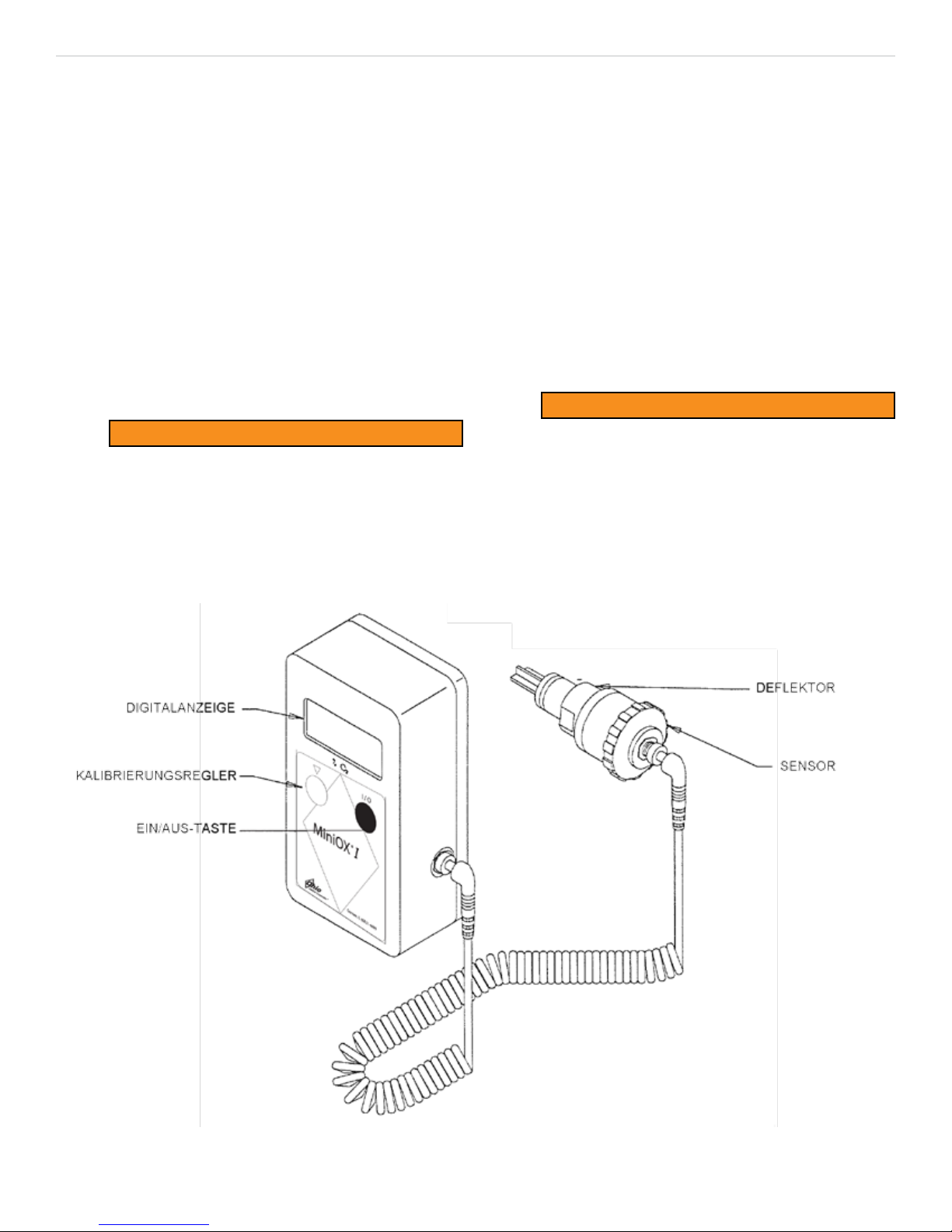
Der MiniOX
®
1 Sauerstoff analysator (Abbildung 1-1):
• Wird durch einfachen Knopfdruck in Betrieb gesetzt
• Wird durch Drehen des Reglers kalibriert
• Ist mit einer leicht lesbaren Digitalanzeige ausgestattet
Jedem Gerät liegt ein T-Stück für den Anschluss eines
Sensors bei. Der galvanische Sauerstoffsensor misst
Sauerstoffkonzentrationen von 0 bis 100 %.
Der Sensor braucht nicht gewartet zu werden, seine
Einsatzdauer beträgt bei normalem medizinischem
Einsatz ein Jahr.
WARNUNG
Vor Inbetriebnahme des MiniOX
®
1 Sauerstoff
analysator sich die Bediener mit dem Inhalt
dieses Handbuches vertraut machen. Andernfalls kann es zu unsachgemäßem Einsatz dieses Gerätes und einer Gefährdung
des Patienten kommen.
MiniOX
Abbildung 1-1.
®
1 Sauerstoff analysator
P/N 711462 (Rev.3) 02/2016
1-1

MiniOX® 1 Sauerstoff analysator Abschnitt 2, Funktion
Abschnitt 2
Funktion
Jedes MiniOX® 1 Sauerstoff analysator ist mit einem
langlebigen, wartungsfreien galvanischen Sauerstoffsensor ausgestattet.
Der Sensor besteht aus zwei Elektroden:
• einer Kathode und
• einer Anode
Die Gold-Kathode ist der Umgebungsluft durch eine
Fluorpolymer-Membran ausgesetzt. Die Blei-Anode ist
in eine Kaliumhydroxidlösung eingetaucht.
Wenn Sauerstoff durch die Membran diffundiert, erzeugt die elektrochemische Reduktion des Sauerstoffs
an der Kathode und die damit verbundene Oxidation
an der Anode elektrischen Strom. Der erzeugte Strom
ist proportional zum Partialdruck des Sauerstoffs in der
Umgebungsluft der Probe. Der daraus resultierende
Strom wird überwacht und bei ausgeglichener Tempera-
tur ampliziert, um die Anzeige anzutreiben.
Der Sensor stellt sich automatisch auf Null zurück; ist
kein Sauerstoff vorhanden, der chemisch reduziert
werden kann bzw. eine Oxidation hervorrufen könnte,
wird nur ein Minimum an Strom erzeugt. Auf der Anzeige werden daher Null Prozent Sauerstoff angezeigt.
2-1
P/N 711462 (Rev.3) 02/2016

MiniOX® 1 Sauerstoff analysator Abschnitt 3, Technische Daten
Abschnitt 3
Technische Daten
Leistungsdaten
Bereich 0-100 % 02
Anzeigeauösung in Schritten von 0,1 % O2
Linearität ± 2 % des Skalenendwertes
Genauigkeit ± 2 % des Skalenendwertes
Anzeige f. leere Batterie “LO BAT” wird angezeigt
Aufwärmzeit nicht erforderlich
Bereich d. Betriebstemperatur 0 bis 40 °C
Bereich d. Lagerungstemperatur -20 bis 55 °C
Luftfeuchtigkeit
Stromanforderungen Eine 9-V Alkalibatterie
Lebensdauer d. Batterie Ca. 1400 Stunden
Maße
Kabellänge 3 m, voll ausgezogen
Sensortyp
Gerät 11,7 cm x 6,4 cm x 3,8 cm
Sensor 4,9 cm x 4,7 cm
0 bis 95 % relative Luftfeuchtigkeit
Galvanischer Sensor, 0 - 100 %
02
Über ein Jahr unter normalen
Lebensdauer d. Sensors
medizinischen
Bedingungen
Sensoren können im Lieferzustand ohne Beeinträchtigung
Lagerungsdauer
FLIESSGEReaktionszeit
wird mit einem in
einem 22 mm TStück montierten
Deektor bei 25
°C gemessen
STÖRSUB-
STANZ
Kohlendioxid 12% <0.1%
Cyclopropan 50% <0.1%
Diethylether 20% <1.5%
Enuran 4% <0.5%
SCHWIND-
IGKEIT
L/MIN.
2 13 21
5 12 20
10 11 19
Störende Gase und Dämpfe
NACH
VOLUMEN% (TROCK-
ENES
ERDGAS)
ihrer Lebensdauer maximal 6
Monate gelagert werden
90% D.
ÄNDERUNG
(SEKUNDEN)
STÖRSUBSTANZ ENT-
SPRICHT O2-PROZENT
97% D.
ÄNDERUNG
(SEKUNDEN)
Störende Gase und Dämpfe
STÖRSUBSTANZ
NACH VOLU-
MEN- %
(TROCKENES
ERDGAS)
STÖRSUBSTANZ
ENTSPRICHT O2-
PROZENT
Methoxyuran 80% <0.2%
Stickstoff 4% <2.3%
Stickstoffoxid 80% <0.2%
Ersatzteile für das Gerät
BESCHREIBUNG TEILE-NUMMER
Gehäuseschraube 637408
Schwalbenschwanzhalterung 474606
40x3/8” stainless stee screw (set
of 4)
Zubehör
ZUBEHÖR TEILE-NUMMER
Alkalibatterie, 9-V 628817
Spiral-Kabel 472045
Deektor 470687
Wartungssatz für den Heimgebrauch
(siehe 4 Anhang A)
Halterung, Pole 474664
Mounting Bracket, Wall
Bedienungs-/Wartungshandbuch (CD) 600700
Operation Manual, printed 711462
Sauerstoffsensor 406931
Sicherungsgurt für den Sensor 634249
T-Stück
Carrying Case
Sleeve Adapter
450000
474682
10023945
473021
710462
474667
Servicing
Inspection and Servicing
Calibration
Enclosure Replacement
Circuit Board Replacement
Button and Sensor Jack
Replacement
SVC-101
SVC-102
SVC-103
SVC-104
SVC-105
3-1
P/N 711462 (Rev.3) 02/2016

MiniOX® 1 Sauerstoff analysator Abschnitt 3, Technische Daten
Elektromagnetische Kompatibilität (EMC)
WARNUNG
Sicherstellen, dass die in den nachstehenden Tabellen angegebenen Abstände für elektromagnetische
Umgebungen für den MiniOX® 1 Sauerstoff analysator eingehalten werden. Andernfalls kann es zu Fehlfunktionen bzw. zu falschen/unzuverlässigen Werten kommen.
Richtlinie und Erklärung des Herstellers — elektromagnetischen Emissionen
®
Der MiniOX
sehen. Der Kunde oder Benutzer des MiniOX® 1 muss sicherstellen, dass die Einsatzumgebung dieser Vorgabe
entspricht.
RF-Emissionen
CISPR 11
RF-Emissionen
CISPR 11
Harmonische Emissionen
IEC 61000-3-2
1 ist zur Verwendung in der nachstehend angegebenen elektromagnetischen Umgebung vorge-
Emissionstest Compliance Elektromagnetische Umgebung — Richtlinie
®
1 verwendet RF-Energie nur für die internen
Gruppe 1
Der MiniOX
Funktionen. Die RF-Emissionen sind daher äußerst
gering, und es ist unwahrscheinlich, dass sie in benachbarten elektronischen Geräten zu Störungen führen.
®
1 eignet sich zur Verwendung in allen
Klasse B
Der MiniOX
Einrichtungen, einschließlich in Privateinrichtungen und
Einrichtungen, die direkt an das öffentliche Niederspannungsnetz angeschlossen sind, welches Privatgebäude
mit Strom versorgt.
Nicht zutreffend Nicht zutreffend
Spannungsschwankungen/
Flicker-Emissionen
IEC 61000-3-3
Nicht zutreffend Nicht zutreffend
3-2
P/N 711462 (Rev.3) 02/2016
 Loading...