


®
Air Compressor
P20-M / P25-M / P30-M
Operation Manual
255549 (Rev. 2) 04/2018
PREFACE
Thank you for purchasing an Ohio Medical air compressor. This manual introduces our Oil-less
Air Compressors to users about all the information required for air compressor installation,
operation and maintenance to ensure the most efcient and trouble-free operation.
In any situation of the product being tampered or repaired with parts not supplied by Ohio
Medical Corporation, serviced by unauthorized personnel, or where recommended maintenance
procedures have not been followed, etc, the warranty is void.
This compressor is intended for compressing atmospheric air only and is strictly prohibited from
compressing any other gas.
Ohio Medical compressors incorporate the latest design of technology and use only components
selected for their high quality and durability to ensure more efcient and durable operation.
We constantly strive to meet the best quality and durability standards and reserve the right to
change specications if required. Thank you again for your interests and continuous support to
of Ohio Medical products.
“Proper Maintenance Leads To Long Service Life”
Safety Precautions:
1. Risk of Hot Surfaces
NEVER touch the discharge tube, cylinder and cylinder head while in operation.
2. Risk of Danger
Do not remove, make adjustment to, or substitute the protection devices. Any adjustment
against the factory setting will automatically void the warranty.
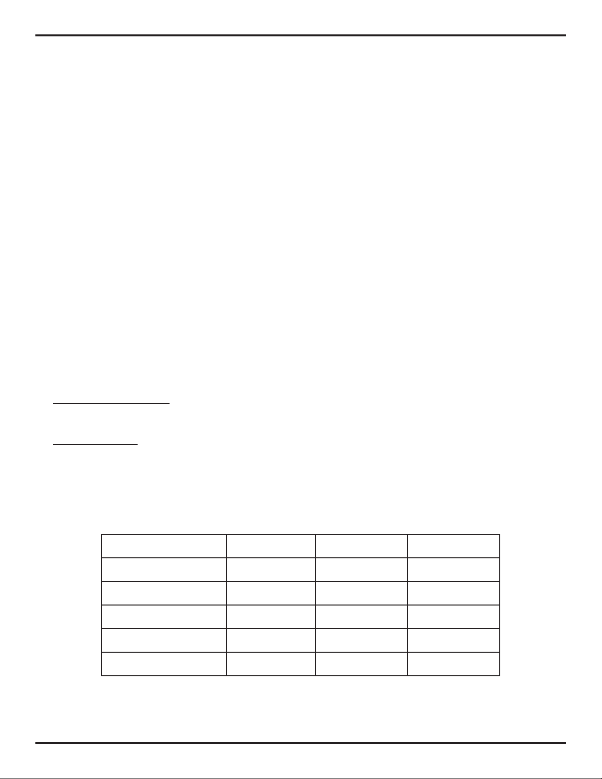
Product Specications
MODEL P20-M P25-M P30-M
PART # 100-0225 100-0226 100-0227
HORSEPOWER 20 25 30
CFM @ 50 PSI 75 90 106
CFM @ 100 PSI 62 76 92
MAX PRESSURE 115 115 115
2 255549 (Rev. 2) 04/2018

INDEX
1. General Description --------------------------------- 3
2. Installation --------------------------------------------- 3
3. V-Belt Adjustment ------------------------------------ 4
4. Safety Device ----------------------------------------- 4
5. Operation ---------------------------------------------- 5
6. Daily Maintenance ----------------------------------- 5
7. Periodical Maintenance ---------------------------- 6
8. Trouble Shooting ------------------------------------- 8
Appendix I Maintenance Record ----------------- 9
9. Spare Parts List -------------------------------------- 11
10. Replacement Parts --------------------------------- 14
1. General Description
1.1 This is an Oil-Less air compressor.
1.2 The cylinder is uniquely designed with W-type arrangement; the high rigid structure
guarantees low-vibration, stable and reliable operation.
1.3 Suction/Discharge valve assembly is made of high strength stainless steel alloy,
which allows quick heat dissipation; low noise level; high efciency; and longer
working life.
1.4 The well-designed ductile iron crankshaft integrated with counterweight is precisely
balanced for smooth, and long-term operation.
1.5 The cylinder is made of aluminum alloy material with cooling n design and special
coating to ensure durable operation.
1.6 Compression ring and guide ring are made of Teon® material to ensure anti-friction
and smooth operation.
1.7 Bearing is totally enclosed with heat resistant grease to ensure long working life.
1.8 Special design on Air Outlet Connectors, for easy maintenance.
2. Installation
2.1 The unit must be located in an area with good ventilation and enough space for
maintenance work.
2.2 Never place the compressor in an area where the atmosphere is dusty, damp or
where corrosive vapors may enter the unit.
255549 (Rev. 2) 04/2018 3
2.3 The machine must be leveled in all directions and must be rmly mounted.
2.4 The ywheel, which is also a fan for circulating air over the cylinder, should never be
placed closer than 12” against the wall, so there is plenty of cooling air circulation.
2.5 Improper installation and maintenance may result in abnormal conditions such as:
1) Insufcient cooling, higher ambient temperature, insufcient cooling space, and
incorrect rotation direction all may easily result in over heating the compressor,
electric motor and compressed air.
2) Placing the unit in a damp and dusty environment may ll the compressed air
with high moisture and create damage to the control system.
3) Severe vibrations will happen when feet are uneven or mounted on a non-solid
oor or nuts and bolts are not securely tightened.
3. V-Belt Adjustment
3.1 Keep the grooves of ywheel and motor pulley clean.
3.2 Align ywheel with pulley groove when installing the V-belts.
3.3 Over tightened belts can cause extra load and shorten the life of the motor bearings.
Overly loose belts can cause V-belt slippage, reduce efciency and break V-belt.
3.4 Maintain the proper belt tension.
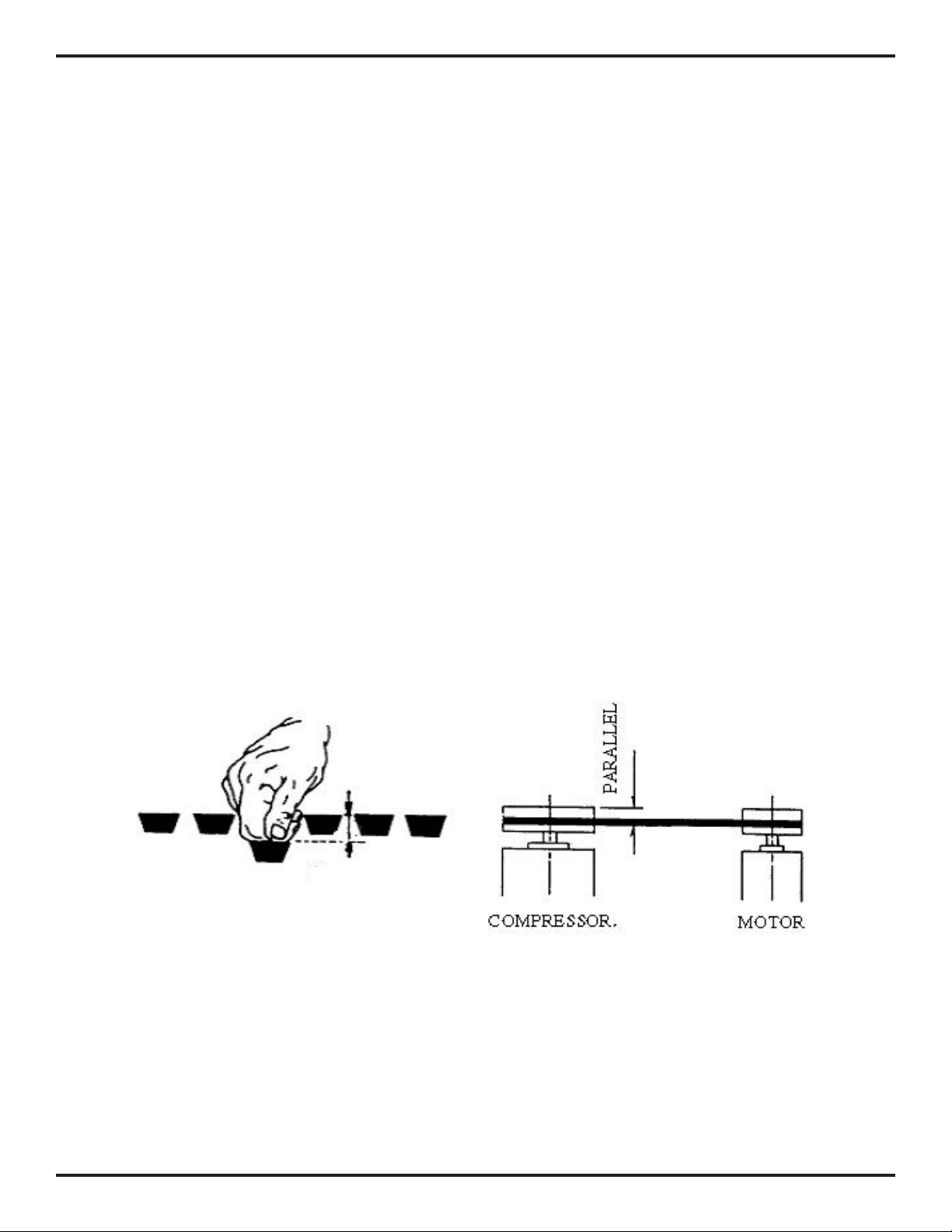
1) Use belt adjuster to correct belt tightness (adjust the tightness according to belt
type, center distance and belt length).
2) Push the belt at its central point by hand to check the belt tightness as below:
Press down rmly on each individual belt and check the deection to be .8” as
shown on the following picture.
.8”
4. Safety Device
4.1 Besides Automatic pressure switch and Automatic unloader as standard protective
components, the following optional safety accessories are also available.
4.2 The air compressor should be equipped with a relief valve to avoid any danger
from excess pressure. The relief valve is designed according to Pressure Vessel
regulations.
4 255549 (Rev. 2) 04/2018

4.3 Motor should follow regulations to be equipped with Magnetic switch and Overload
relay to avoid the motor current over pre-setting limit.
5. Operation
5.1 Checks before starting
1) Make sure that electrical connections comply with local electrical regulations.
2) Check set bolts and nuts to be securely tight.
3) Check V belt for proper tension.
4) Check that electrical cables are correct and securely tight.
5) Check that voltage is correct.
5.2 Checks under operation
1) If rotating direction of compressors is right.
2) If compressed air pressure rises normally while running.
3) If current of the motor remains within standard level under loading condition.
4) Stay away from extremely hot components.
6. Daily Maintenance
6.1 Clean the Belt Guard and the ventilation area of the air compressor frequently to
ensure proper cooling.
6.2 Inspect if there is unusual noise or if temperature is too high.
6.3 Check if there is abnormal vibration.
6.4 Check if voltage & current of the power supply are correct.
255549 (Rev. 2) 04/2018 5

7. Periodical Maintenance
7.1 Check the below parts periodically.
HR
Check items
Intake Filter
V-belt loosen
Bolt(Nut) loosen
Valve assembly
leaking
Must Do
Compression ring
Guide ring
Connection Rod
a. Big end
b. Small end
Cylinder
250
(1 month)
3000
(12
months)
6000
(24
months)
8000
(30
months)
Instructions
Clean with brushes and
compressed air. (replace
once 6 months.)
Adjust and follow
instructions in operation
manual
Tighten bolts(nuts) with
proper tools.
Inspect & clean spare
parts. Test if leaking or
not.
Check/Replace
Check/Replace
If function well or any
noise
Check./Replace
Remarks: 1. --- Check/Maintain, Replace when necessary
2. --- Replace
7.2 Maintenance, repair or modications must only be carried out by qualied personnel
with authorized training.
1) When the air compressor is working under normal conditions, we recommend
to maintain as per above time table. If required, you may shorten the
maintenance interval.
2) To ensure efcient compression, any piece of Compression Ring and Guide
Ring should be replaced if it’s worn-out as shown on the table below.
Ø130
Spare
part
Compression ring Guide ring
The radial direction
thickness of new pieces
10 2.4
(mm)
The radial direction
thickness of worn-out
8 1.8
limit (mm)
6 255549 (Rev. 2) 04/2018

3) Check the thickness of compression ring and guide ring periodically. Record
the data in your service log.
4) If the compressor has not run for a long time, it should be set on no-load
running for at least 30 minutes per month to keep the bearings and related
parts in regulator running condition.
7.3 Key points during Disassembly and Assembling:
1) Before disassembly, be sure to turn off the power and release the pressure of
air tank to ensure safety.
2) After disassembly, place the parts in order on a clean box or paper to enable
re-assembly later.
3) While assembling, pay attention to the cleanness of environment and working
tools, especially for those parts like piston, compression ring, guide ring,
cylinder and valve assembly. Avoid dust and contamination of these parts.
4) Pay attention to the direction of compression ring and guide ring . If not, the air
delivery will be decreased.
5) The bearing is totally enclosed with heat resistant grease. If there is abnormal
noise, please contact local service agent for service.
6) While assembling, be sure to tighten the screws, nuts and related parts
properly.
7) After disassembly, the liner (the liner on the cylinder head and the cylinder)
should be replaced with a new one and then re-assembled.
255549 (Rev. 2) 04/2018 7

8. Trouble Shooting
On
running
On
running
Problem Possible
Valve assembly broken; or liner
Pressure
can’t be
raised
properly
Abnormal
pressure
Unusual
sounds
leaking
Intake lter blocked V V
Pipe leaking V V
Piston ring or cylinder worn V V
V-belt loosen or worn-out V V V
Fault unloading system V V
V-belt loosen or worn-out V V V
Set bolts loosen V V V
Fault motor V V
Uneven foundation oor V
Defective bearing V
Piston hits valve assembly V V
Guide rings worn-out V
Action
Check Repair Replace
V V
On
running
On
running
On
running
Unable
to start
Abnormal
vibration
Abnormal
temperature
Overheat
motor
Motor fail to
start
Uneven foundation oor V
V-belt loosen or worn-out V V V
Set bolts loosen V V
Abnormal piping V V
Wrong rotation of motor V
High ambient temperature V
V-belt loosen or worn-out V V
Valve assembly broken V V
Compression rings worn-out V
Bearing broken V
Fault motor V V
Electrical connection loosen V V
Motor current protector is tripped V V
Fault motor V V
Piston bearing burn out V V
Under safety protection activating
situation
V
Unusual
motor sound
8 255549 (Rev. 2) 04/2018
Low voltage V V

Appendix I: Maintenance Record
Date
Hour
Meter
Record
Service
Tech
255549 (Rev. 2) 04/2018 9

10 255549 (Rev. 2) 04/2018

NO Description Qty
6
Discharge copper tube
41 Spring washer 6
42 Flange joint 1
43 Flange joint 2
44 Flange joint 1
45 Packing 4
46 Set bolt 8
47 Set bolt 4
48 Plug 4
49
4
assembly
Unloading piston
assembly
50
51 Unloading holder 4
52 O-Ring 8
53 Set bolt 8
54 Spring washer 8
55 Elbow (unloading) 1
56 Tee joint (unloading) 3
57 Unloading tube assembly 3
58 Filter assembly 3
59 Front cover 1
60 Block nameplate 1
21 Rear bearing seat 1
22 O-Ring 1
23 Set bolt 10
24 Spring washer 10
25 Bearing 2
26 Crank shaft 1
27 Connecting rod assembly 4
28 Washer 3
29 Counter weight 1
30 Set bolt 2
31 Flywheel 1
32 Key 1
33 Set bolt 1
34 Washer 1
35 Spring washer 1
36 Fan 1
37 Counter weight 1
38 Spring washer 1
39 Set bolt 1
NO Description Qty
1 Cylinder head 4
2 Head packing 4
3 Set bolt 24
4 Spring washer 24
5 Set bolt 4
6 Filter assembly 4
7 Flange 4
8 Set bolt 16
Compressor Spare Parts List
255549 (Rev. 2) 04/2018 11
NO Description Qty
9 Inlet valve assembly 4
11 Packing 4
10 Cylinder 4
12 Set bolt 16
13 Spring washer 16
14 Piston 4
15 Compression ring 12
16 Guide ring 8
17 Piston pin assembly 4
18 Set bolt 8
40 Set Bolt 5
19 Crankcase 1
20 Set bolt 2

12 255549 (Rev. 2) 04/2018

NO Description Qty
1
Compressor parts
diagram
48 Set bolt 1
49 Washer 1
50 Spring washer 1
51 Discharge copper tube 1
52 Discharge copper tube 1
53 Copper tube nut 4
54 Copper tube sleeve 4
55 Unloading copper tube 1
56 Tube tting 1
57 Fixed seat 1
58 Set bolt 2
59 Spring washer 2
60 Automatic drain valve 1
61 Plastic joint 1
62 Rubber tube 1
63 Rubber tube 1
64 Rubber tube 1
65 Arrow mark sticker 1
66 Sticker 1
67 Operating manual 1
68
69 Certicate of compliance 1
70 PP adherent bag 1
71 Cotton string 1
NO Description Qty
1
Discharge copper tube
25 Safety net xed plate 1
26 Fixed plate 1
27 Set bolt 18
28 Spring washer 18
29 Washer 18
30 Set bolt 2
31 Spring washer 2
32 Washer 2
33 Discharge Pipe 1
34 Set bolt 2
35 Spring washer 2
36 Cooler assembly 1
37 Cooler assembly 1
38 Cooler assembly 1
39 Set bolt 9
40 Spring washer 9
41 Washer 9
42 Tube tting 3
43 Elbow 3
44
1
assembly
Discharge copper tube
45
1
assembly
Discharge cooper tube
assembly
46
47 Copper tube xed plate 1
1 Seat Plate 1
2 Compressor body 1
3 Set bolt 4
4 Spring washer 4
5 Motor pulley 1
6 Set bolt 1
7 Set bolt 1
8 Set bolt 4
Compressor Spare Parts List
255549 (Rev. 2) 04/2018 13
NO Description Qty
9 Spring washer 4
11 Set nut 4
10 Washer 4
12 Set bolt 2
13 Set nut 2
14 Rubber V-belt 3
15 Safety net 1
16 Safety net 1
17 Safety net 1
18 Safety net xed plate 1
19 Set bolt 10
20 Set bolt 29
21 Washer 39
22 Washer 39
23 Safety net xed seat 3
24 Safety net xed plate 1

10. Replacement Parts
MODEL P20-M P25-M P30-M
Compressor Module w/o Motor 230103 230104 230105
Complete Module Number 100-0225 100-0226 100-0227
Motor HP (60 Hz) 20 25 30
Motor 244285 244286 244287
Temperature Switch (4) 211038 211038 211038
Auto Drain 3/8" NPT 211203 211203 211203
Relief Valve 1/2" 125 PSI 232259 232259 232259
Unloader Solenoid 246029 246029 246029
Vibration Pad (4) 248008 248008 248008
14 255549 (Rev. 2) 04/2018

BLANK PAGE
255549 (Rev. 2) 04/2018 15

®
North America
United States
Customer Service, Distribution Center
Technical Support, Sales and Service
Equipment Service Center
Ohio Medical LLC
1111 Lakeside Drive
Gurnee, IL 60031 USA
P: +1 866 549 6446
F: +1 847 855 6218
www.ohiomedical.com
© 2018 Ohio Medical LLC. This document contains information that is proprietary and condential to Ohio Medical LLC.
Use of this information is under license from Ohio Medical LLC. Any use other than that authorized by Ohio Medical LLC is
prohibited. Ohio Medical, the Ohio Medical logo, are registered trademarks of Ohio Medical LLC.
255549 (Rev. 2) 04/2018
 Loading...