

Ohio Medical Area, Master, Combo Maintenance Manual
OHIO MEDICAL CORPORATION
Medical Gas Alarms
Installation and
Maintenance Manual
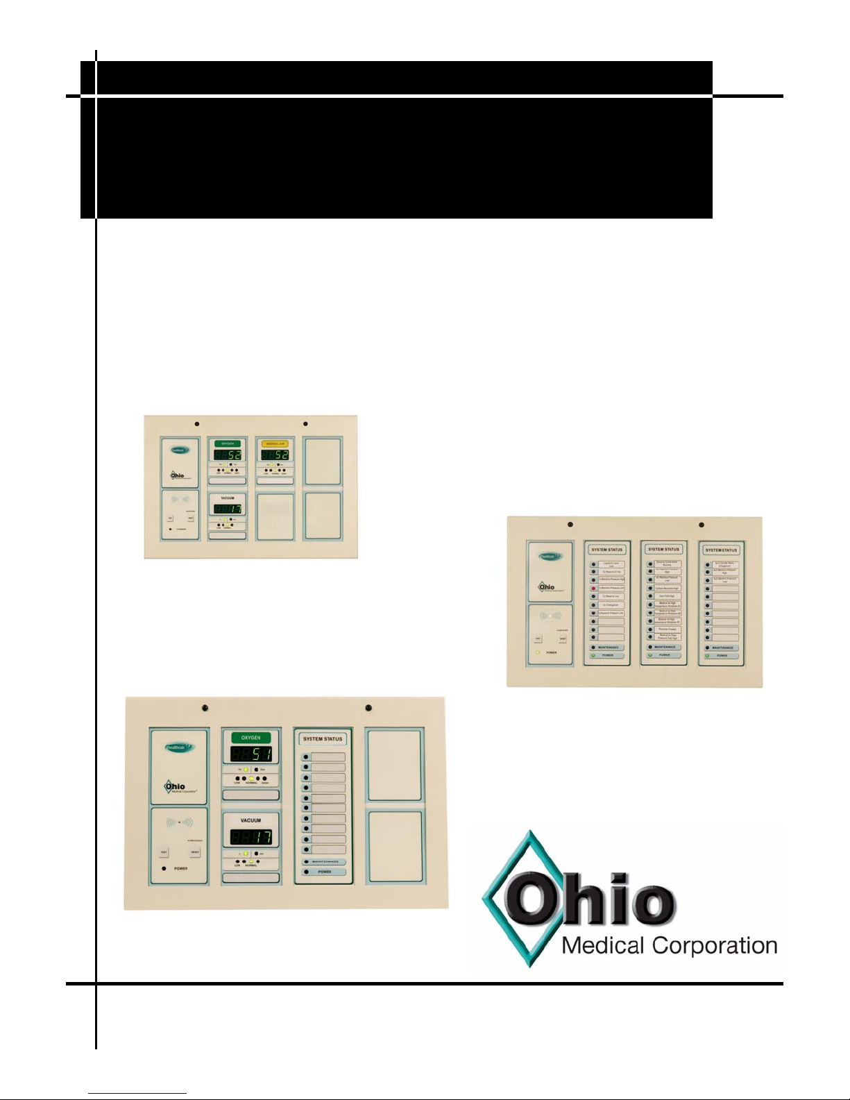
Area Alarm
Combo Alarm
Master Alarm
P/N 255098 (Rev.8) 07/08

Page 2
NOTES
Ohio Medical Corporation., 1111 Lakeside Drive, Gurnee, IL 60031-4099 (800/448-0770) www.ohiomedical.com
Medical Gas Alarm Manual ■ 255098 (Rev.8) 07/08

Page 3
SQUIRE-COGSWELL COMPANY WAS FORMED IN 1916 AS A SUPPLIER OF RAILWAY AND FOUNDRY
EQUIPMENT IN CHICAGO. IT CONTINUED ALONG THIS BUSINESS PATH UNTIL 1951 WHEN WALTER F.
DEVEREUX PURCHASED THE COMPANY. AT THAT TIME THE COMPANY BEGAN TO CONCENTRATE ITS
EFFORTS ON A LINE OF NON-LUBRICATED AIR COMPRESSORS AND VACUUM PUMPS AND A NICHE
WAS FOUND SERVICING THE PRINTING PRESS INDUSTRY. UTILIZING THIS EXPERTISE, THE COMPANY
BEGAN TO SUPPLY CUSTOM PUMPING PACKAGES FOR A VARIETY OF APPLICATIONS AND IN THE
EARLY 1950’S SQUIRE-COGSWELL SOLD ITS FIRST HOSPITAL VACUUM PUMP PACKAGE, THE
CORNERSTONE OF TODAY’S BUSINESSES AND PRODUCT LINES.
IN 1962, MR. HERBERT SCHIFTER, MR. DEVEREAUX’S SON-IN-LAW TOOK OVER AS PRESIDENT.
MR. SCHIFTER WAS THE ORIGINAL INVENTOR OF THE “DIAMOND ONE” GAS OUTLET WHICH HE
PATENTED IN 1959. THE BUSINESS GREW SIGNIFICANTLY AS A SUPPLIER OF CUSTOM DESIGNED
AND CONSTRUCTED VACUUM AND AIR COMPRESSOR SYSTEMS FOR MEDICAL AND INDUSTRIAL USE.
TO DATE, SQUIRE-COGSWELL HAS MANUFACTURED OVER 15,000 HOSPITAL AIR COMPRESSOR AND
VACUUM PUMPING SYSTEMS THAT HAVE BEEN INSTALLED AROUND THE WORLD BEARING A VARIETY
OF VERY WELL-KNOWN TRADE NAMES.
TODAY IN THE THIRD GENERATION OF FAMILY OWNERSHIP AND MANAGEMENT, SQUIRE-COGSWELL
COMPANY CONTINUES TO SERVE THE WORLDWIDE NEEDS FOR HOSPITAL VACUUM PUMPING AND AIR
COMPRESSOR PACKAGES ALONG WITH THE COMPLETE HEALTHCAIR® MEDICAL GAS PIPELINE
OFFERING.
IN 1962, THE SUBSIDIARY COMPANY, AEROS INSTRUMENTS, INC., WAS FORMED TO MANUFACTURE
SUCTION AND OXYGEN THERAPY EQUIPMENT FOR THE MEDICAL COMMUNITY. TODAY AEROS
CONTINUES TO MANUFACTURE ALL OF THE SALES REQUIREMENTS FOR ONE OF THE LARGEST
SUPPLIERS OF SUCH EQUIPMENT IN THE WORLD. AT THE SAME TIME, AEROS INSTRUMENTS
PRODUCES AND SELLS IT’S OWN LINE OF PORTABLE SUCTION MACHINES UNDER THE WELL-KNOWN
NAMES OF MOBLVAC ®, INSTAVAC ®, CARE-E-VAC ® AND TOTE-L-VAC ®.
HE AEROS INSTRUMENTS SUBSIDIARY, WHICH IS AN ISO 13485 REGISTERED COMPANY AND IS A
T
GOVERNMENT REGISTERED MEDICAL DEVICE MANUFACTURER, PRODUCES THE HEALTHCAIR®
S
ERIES OF MEDICAL GAS PIPELINE EQUIPMENT INCLUDING THE MEDICAL GAS OUTLETS AND
EDICAL GAS ALARM SYSTEMS.
M
SQUIRE-COGSWELL/AEROS INSTRUMENTS INC. ARE THE ONE SOURCE FOR ALL MEDICAL GAS
PUMPING, MEDICAL GAS PIPELINE EQUIPMENT AND MEDICAL ASPIRATION EQUIPMENT. FROM
CUSTOM DESIGNED PUMPING SYSTEMS TO THE MOST MODERN LINE OF ASPIRATION EQUIPMENT
AND MEDGAS PIPELINE AVAILABLE ANYWHERE, SQUIRE-COGSWELL–AEROS DOES IT ALL. NO
OTHER SUPPLIER SURPASSES OUR CONTINUITY OF EXPERIENCE AND LEADERSHIP IN THE MEDICAL
GAS PUMPING, PIPELINE AND ASPIRATION MARKETS.
Ohio Medical Corporation., 1111 Lakeside Drive, Gurnee, IL 60031-4099 (800/448-0770) www.ohiomedical.com
Medical Gas Alarm Manual ■ 255098 (Rev.8) 07/08

Page 4
T A B L E O F C O N T E N T S
1.0 Responsibilities................. .......... .......... ......... .......... .......... .................... .......... 5
1.1 Installer .. .................... .......... .......... ......... .......... .......... .................... .......... 5
1.2 User ....... .................... .......... .......... ......... .......... .......... .................... .......... 5
2.0 System Description & Function .... .......... ......... .......... .......... .................... .......... 5
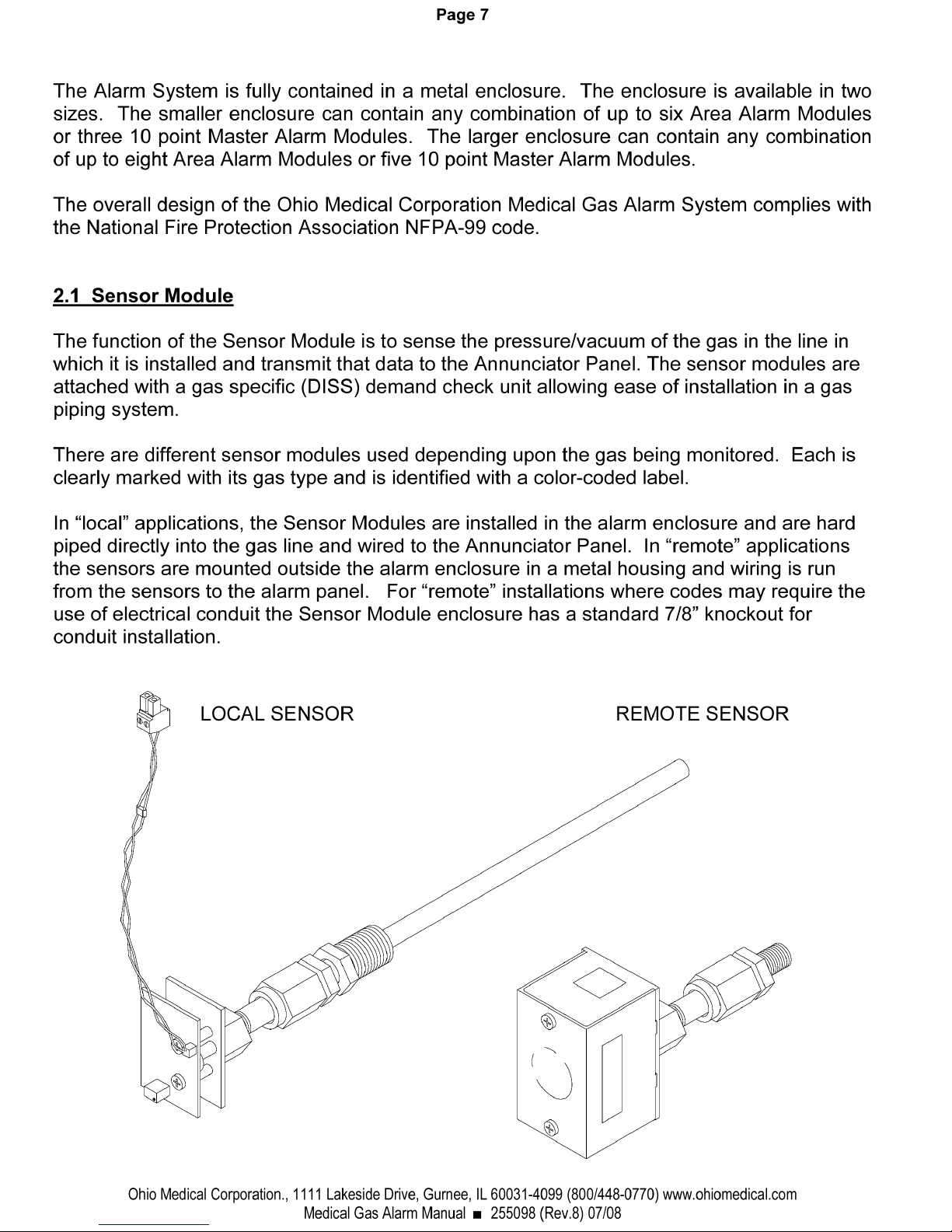
2.1 Sensor Module........... .......... .......... ......... .......... .......... .................... .......... 7
2.2 Annunciator Panel...... .......... .......... ......... .......... .......... .................... .......... 8
2.3 Area Alarm Module .... .......... .......... ......... .......... .......... .................... .......... 9
2.4 Master Alarm Module. .......... .......... ......... .......... .......... .................... .......... 9
3.0 Labeling ....... .................... .......... .......... ......... .......... .......... .................... .......... 10
3.1 Area Alarm Module Labeling. .......... ......... .......... .......... .................... .......... 10
3.2 Master Alarm Module Labeling ........ ......... .......... .......... .................... .......... 10
4.0 Installation.... .................... .......... .......... ......... .......... .......... .................... .......... 12
4.1 Mounting Instructions Prior to Drywall & Plaster Installation ................. .......... 12
4.2 Installation & Wiring Instructions After Drywall & Plaster Installation .... .......... 13
4.3 Area Alarm Remote Output Signal Connections... .......... .................... .......... 16
4.4 Master Alarm Connections From Source Equipment....... .................... .......... 17
4.5 Dry Contacts Master Alarm Output Connections .. .......... .................... .......... 18
4.6 Remote Audible Alarm Installation... ......... .......... .......... .................... .......... 19
4.7 Initial Start-Up Checks .......... .......... ......... .......... .......... .................... .......... 20
5.0 Programming .................... .......... .......... ......... .......... .......... .................... .......... 20
5.1 Programming Chart.... .......... .......... ......... .......... .......... .................... .......... 21
5.2 Default Settings Tables......... .......... ......... .......... .......... .................... .......... 22
5.3 Calibration Precautions......... .......... ......... .......... .......... .................... .......... 23
5.4 Programming Change Example....... ......... .......... .......... .................... .......... 24
5.5 Review Area Alarm Programming Parameters ..... .......... .................... .......... 24
5.6 Master Alarm Programming Mode ... ......... .......... .......... .................... .......... 24
6.0 LonWorks® Capabilities ... .......... .......... ......... .......... .......... .................... .......... 25
7.0 Specifications.................... .......... .......... ......... .......... .......... .................... .......... 25
8.0 Troubleshooting ................ .......... .......... ......... .......... .......... .................... .......... 26
9.0 Cleaning....... .................... .......... .......... ......... .......... .......... .................... .......... 27
10.0 Service Item List ............... .......... .......... ......... .......... .......... .................... .......... 27
11.0 Warranty ...... .................... .......... .......... ......... .......... .......... .................... .......... 29
Ohio Medical Corporation., 1111 Lakeside Drive, Gurnee, IL 60031-4099 (800/448-0770) www.ohiomedical.com
Medical Gas Alarm Manual ■ 255098 (Rev.8) 07/08

Page 5
1.0 Responsibilities
The information contained in this Installation and Operation Maintenance Manual, pertains only to the
Ohio Medical Corporation medical gas alarm system. The medical gas alarm system will operate in
conformance with the descriptions outlined in this manual only when it is operated, maintained and
serviced properly and in compliance with the instructions contained herein.
1.1 Installer Responsibilities
All contents of the alarm are shipped in ISTA approved packaging. The alarm should be handled,
installed, and tested per the recommended practices in this manual. Should such repair or
replacement become necessary, contact Ohio Medical Customer Service (800-448-0770) for original
equipment replacement parts.
1.2 User Responsibilities
The alarm should be tested and examined periodically. Any parts which are found to be damaged,
corroded, contaminated, etc. should be replaced. Possible replacement items are listed on pages 26
to 27 in this manual. Should such repair or replacement become necessary, contact Ohio Medical
Customer Service (800-448-0770) for original equipment replacement parts.
2.0 System Description & Function
The Ohio Medical Corporation Medical Gas Alarm System is designed to continuously monitor the
status of source equipment and gas line pressure of medical gases. The system is comprised of Area
Alarm Modules which monitor and indicate the gas pressure or vacuum level of a specific gas at a
specific point in the hospital and Master Alarm Modules which monitor source equipment such as
oxygen systems, air compressors or vacuum pumps.
The Alarm System monitors gas line pressure with sensors. The Alarm’s Annunciator determines the
status of the pressure and the pressure is displayed on an area alarm module. The alarm module also
has trend light LED’s to show that the displayed pressure is either in a normal, caution, or a high or
low alarm condition.
The Alarm System also has a master alarm module to monitor 10 condition points from source
equipment. Each point represents a condition that the source equipment might have. A dry contact
version of the master alarm is also available to relay conditions of the source equipment to a building
management system.
More detailed descriptions of each module is explained on pages 5 through 8.
Ohio Medical Corporation., 1111 Lakeside Drive, Gurnee, IL 60031-4099 (800/448-0770) www.ohiomedical.com
Medical Gas Alarm Manual ■ 255098 (Rev.8) 07/08


Page 8
2.2 Annunciator Panel
The Annunciator Panel is the main processing board for the Medical Gas Alarm System. The
Annunciator Panel accepts information by two different means. For gas pressure, the input
signal comes from the Sensor Module and goes to the annunciator to evaluate the pressure
being observed. This information is then transmitted directly to the corresponding Area Alarm
Module where the pressure or vacuum is displayed via the ribbon cable. For source
equipment, a condition is relayed to a point on a master alarm module first and then
transferred to the Annunciator via the ribbon cable. In normal operation, the Annunciator
continuously monitors all pressure, vacuum, and source equipment for alarm conditions.
When an alarm condition is detected, an audible alarm (approximately 80 decibels measured
at 3 feet) will sound and the appropriate red LED will illuminate from the corresponding Area
or Master Alarm Module. The audible alarm will sound under one of the four conditions listed
below.
■ When the pressure input increases above a specified high set-point
□ When the pressure or vacuum decreases below a specified low set-point
■ When an alarm condition is detected on the Master Alarm Module
■ When one of the Sensor Module’s wiring has become disconnected
There are two momentary push buttons on the Annunciator Panel, which are labeled as
“TEST” and “ALARM SILENCE/RESET”. To stop the audible alarm from sounding, press the
“ALARM SILENCE” button. However, the alarm will re-sound again after the specified repeat
time has elapsed unless the alarm condition has been cleared. When a new alarm condition
is detected from another alarm panel, the audible alarm will sound again. Each time the
“Alarm Silence” button is pressed the alarm repeat time will reset. To review if the alarm’s
displays and audible alarm are in working order, press the “TEST” button for approximately 3
seconds. While testing, all display segments and independent LED’s will be illuminated and
the audible alarm will sound.
The Annunciator has a relay for wiring an external buzzer to a remote location. This relay
energizes the external buzzer when the audible alarm sounds.
A communications port is provided on the Annunciator Panel that allows for integration with a
LonWorks® network system allowing the medical gas alarm system to communicate with a
LonWorks® capable building management system.
Ohio Medical Corporation., 1111 Lakeside Drive, Gurnee, IL 60031-4099 (800/448-0770) www.ohiomedical.com
Medical Gas Alarm Manual ■ 255098 (Rev.8) 07/08
Page 9
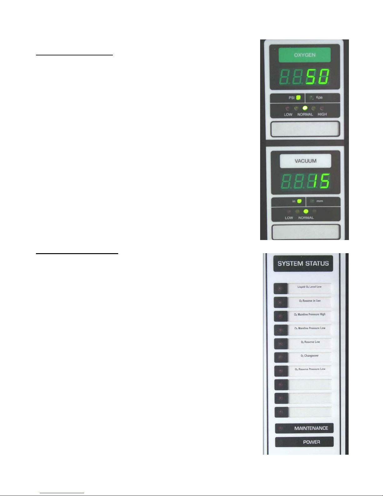
2.3 Area Alarm Panel
The Area Alarm Panel provides a digital display of the actual gas
line pressure or vacuum being monitored. The module has three
different color trend lights to indicate three different conditions of
the gas pressure. These colors are green, yellow and red for
normal, caution, and high or low pressure indications
respectfully. The trend lights and how they correspond to range
in pressure is explained in more detail while programming in
Chapter 5.2 on page 21. When an alarm detects a “LOW” or
“HIGH” condition the corresponding red LED on the Area Alarm
Panel will be illuminated and an audible alarm will sound from
the Annunciator Panel. The red LED will stay illuminated until the
alarm condition has been corrected and the “Reset” button is
pressed.
The two LED’s above the colored trend lights indicates which
unit of measure is being displayed. The units are English
(Standard) or Metric units for pressure or vacuum accordingly
and can be changed to whichever units when programming.
The Area Alarm Module has dry contacts on the backside to
connect to a pair of contacts on a Master Alarm Module for
remote monitoring purposes.
2.4 Master Alarm Panel
The Master Alarm Panel monitors dry contacts from source
equipment or area alarm panels. Each individual Master Alarm
Panel can monitor up to 10 signals. Each pair of contacts is
either configured for normally open or normally closed operation.
The default mode is normally closed per NFPA code. The
Master Alarm panel may be easily labeled to indicate each of the
conditions being monitored. A Dry Contact Master Alarm Module
is also available for computer interface or service to a building
management system.
In operation, the unit continuously monitors for alarm conditions.
Except for the green “POWER” indicator, all Master Alarm Panel
LED lamps will be off when there are no alarm conditions
present. When an alarm condition is detected, the
corresponding LED on the Master Alarm Panel will flash and the
audible alarm from the Annunciator Panel will sound. The LED
will continue to flash until the alarm condition has been corrected
and the alarm has been reset. If two or more alarm condition
occur at the same time, the most recent alarm will flash and the
other existing alarms will remain in constant illumination. Any
alarm will remain lighted until the respective alarm condition has
been corrected and the alarm has been reset.
Ohio Medical Corporation., 1111 Lakeside Drive, Gurnee, IL 60031-4099 (800/448-0770) www.ohiomedical.com
Medical Gas Alarm Manual ■ 255098 (Rev.8) 07/08

Page 10
3.0 Labeling Alarm Modules
Each application needs to describe the medical gas conditions and locations that are unique
to each installation. To provide clear and precise representation of this information, the area
and master alarm modules allocate a sufficient size area on their displays to label this
Information. To simplify in labeling the area or master alarms, please try to label these
assemblies prior to connecting leads to the dry contacts.
3.1 Labeling Area Alarm Modules
For ease of referencing what specific location the area alarm is representing, a window on
the bottom of each alarm is provided to label this information. See Labeling Module
Diagram on figure 3.
1. Make sure the alarm assembly is turned off prior to servicing.
2. Referencing figure 9, disconnect the cable ribbons leading to and from adjacent PCB/
Weldment assemblies.
3. Unfasten top and bottom hex nuts only. Do not unscrew the button head screws
attaching the circuit board to the weldment plate.
4. Extract the area alarm PCB/Weldment assembly from the front panel assembly.
5. Either slide required label through pocket provided in mylar screen or affix required label
directly over screen per Figure 3.
6. Refasten the master alarm assembly to the front panel with the hex nuts.
7. Reconnect cable ribbons as demonstrated in figure 6 on page 14 of your manual.
3.2 Labeling Master Alarm Modules
For ease of referencing what specific alarm conditions are present, each LED on the master
alarm module can be labeled to identify what condition it is represent. See Labeling Module
Diagram on figure 3.
1. Make sure the alarm assembly is turned off prior to servicing.
2. Disconnect cable ribbons from master alarm board.
3. Unfasten top and bottom hex nuts only. Do not unscrew the button head screws
attaching the circuit board to the weldment plate.
4. Extract master alarm PCB/Weldment assembly from the front panel assembly
5. Either slide required label through pocket provided in mylar screen or affix required
label directly over screen per Figure 3. Note that the “MA 1” dry contact will activate
the top LED, the “MA 2” contact activates the second from the top, and then follows
on down in that consecutive order.
Ohio Medical Corporation., 1111 Lakeside Drive, Gurnee, IL 60031-4099 (800/448-0770) www.ohiomedical.com
Medical Gas Alarm Manual ■ 255098 (Rev.8) 07/08
 Loading...