

Page 1
®
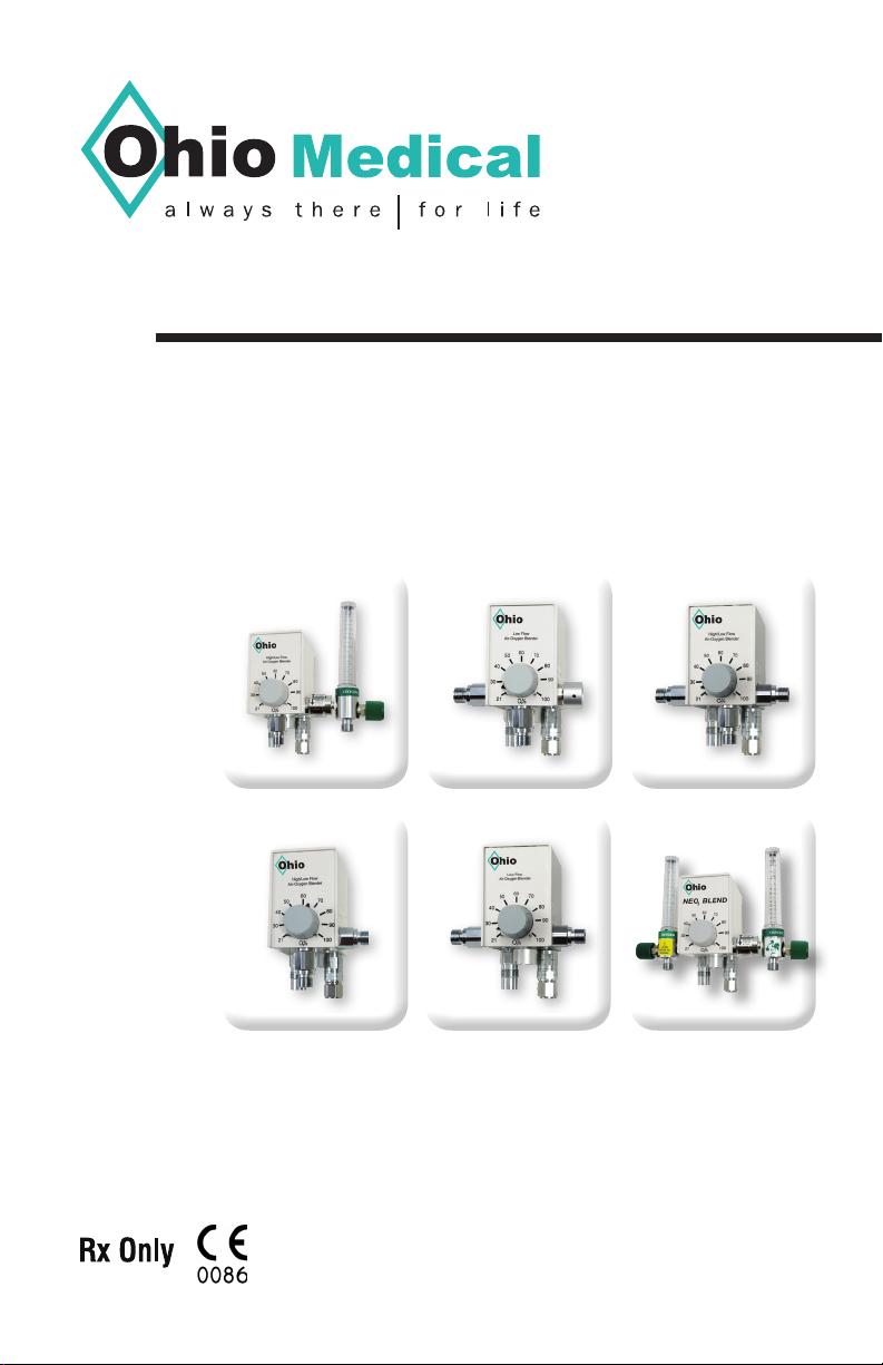
Air/Oxygen
Blender
Instruction Manual
6700-0494-200 (Rev. 6) 04-2018
Page 2
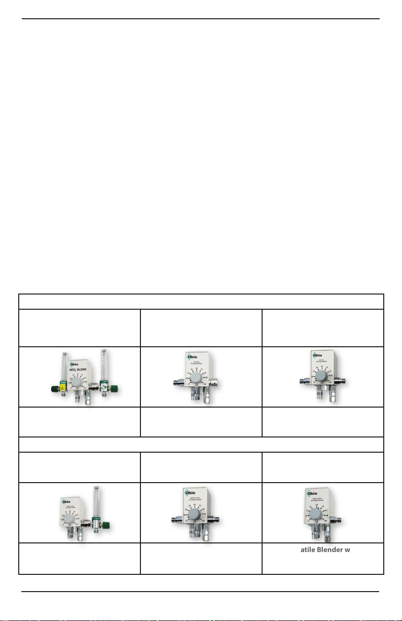
TABLE OF CONTENTS
ADDENDUM 1 (Bleed Knob) & ADDENDUM 2 (Bleed Switch)........................................3
RECEIVING/INSPECTION ............................................................................................... 4
READ ALL INSTRUCTIONS BEFORE USING ................................................................ 4
DEVICE DESCRIPTION ................................................................................................... 4
INTENDED USE ............................................................................................................... 4
WARNINGS AND CAUTIONS .......................................................................................... 4
EXPLANATION OF SYMBOLS ........................................................................................5
SPECIFICATIONS ............................................................................................................6
INTRODUCTION AND OPERATION ................................................................................ 7
SETTING UP THE BLENDER .......................................................................................... 8
TESTING THE BLENDER ................................................................................................ 8
USING THE BLENDER .................................................................................................... 9
TROUBLE SHOOTING GUIDE ...................................................................................... 10
BLENDER WARRANTY ................................................................................................. 11
CLEANING INSTRUCTIONS ......................................................................................... 11
NEO
Blend with
2
Unique Bleed Switch
6750-0018-9XX
MODEL IDENTIFIER
LOW FLOW BLENDERS
Blender with
ON/OFF Knob
6750-0019-9XX
Standard Low Flow
6750-0020-9XX
Unique ON/OFF Bleed switch
Blender with 2
assembled Flowmeters
Blender equipped with
ON/OFF Bleed Knob
HIGH/LOW FLOW BLENDERS
High/Low with
Unique Bleed Switch
6750-0026-9XX
Unique ON/OFF Bleed switch
Blender with 1
assembled Flowmeter
2 6700-0494-200 (Rev.6) 04-2018
3 Ports
6750-0025-9XX
High/Low Blender
with 3 Ports
Versatile 2 Port Blender
Standard
High/Low Flow
6750-0024-9XX
Versatile Blender with
right and bottom Port
Page 3

ADDENDUM 1Bleed Knob Model: 6750-0019-9XX
Low Flow with Bleed Knob
Blender model 6750-0019-9XX has a bleed knob that has been installed in lieu of the right side output
port. This enables the user to maintain accurate concentrations when using the bottom or left outputs
for all ows within the specication of the blender with a simple turn of the knob.
A label attached to the side of the blender indicates how to position the knob for accurate
concentrations at settings less than or greater than the ow rate indicated. The knob must be pushed
in prior to turning.
ADDENDUM 2Low Flow with Bleed Switch (NEO2 Blend) Models: 6750-0018-9XX (Right and Left Flowmeter)
Blender models 6750-0018-9XX is always offered with assembled owmeters. The owmeter on the
right side is mounted to a uniquely designed rotating bleed switch that is used in the same manner
as the knob described in Addendum 1. Any time these blenders are used in a ow range requiring
the bleed to be active (see the Flow Table in Section 4), rotating this owmeter as described below
will activate the bleed as well as the owmeter. Even if the owmeter is not to be used, positioning it
vertically so the bleed is active allows the blender to be used with its lower ows.
The ow rate for these owmeters should be set using the center of the ball.
RIGHT SIDE FLOWMETER
The right side owmeter and the blender bleed are inactive when the owmeter is angled towards
the front of the blender. To activate the owmeter and initiate the required bleed for lower ows, push
the owmeter in towards the side of the blender and then rotate it clockwise (towards the back) to its
vertical position. The internal bleed will now be active and the ow rate may be set using the knob on
the owmeter. As long as the owmeter is in this position, any output port can be used for low ows
even if the owmeter itself is not being used. To return the owmeter and bleed to its off (inactive)
state, return it to its angled position by pushing it in and rotating it counterclockwise (towards the front).
LEFT SIDE FLOWMETER
CAUTION: The owmeter on the left side is stationary. Do not try to turn it.
If the owmeter on the left side is to be used for ows requiring a bleed for accuracy (see the Flow
Table in Section 4), be sure the knob (see Addendum 1) or right-side owmeter (see above) is set
properly.
This owmeter is meant for ows above 3 LPM. It may, however, be used below 3 LPM with the
following consideration; when set below 3 LPM, turn on the required bleed by setting the right side
owmeter to its vertical position following the procedure as described above. Even though the
owmeter on the right is not being used, having it in the vertical position activates the internal bleed
thereby guaranteeing O2 accuracy while using the left side owmeter at ows below 3 LPM.
High-Low with Bleed Switch Blender 6750-0026-9XX (Right Flowmeter)
Blender models 6750-0026-9XX are always offered with an assembled owmeter. The owmeter on
the right side is mounted to a uniquely designed rotating bleed switch that is used in the same manner
as the knob described in Addendum 1. Any time these blenders are used in a ow range requiring the
bleed to be active, rotating this owmeter as described below will activate the bleed as well as the
owmeter. Even if the owmeter is not to be used, positioning it vertically so the bleed is active allows
the blender to be used with its lower ows.
The ow rate for these owmeters should be set using the center of the ball.
RIGHT SIDE FLOWMETER
The right side owmeter and the blender bleed is inactive when the owmeter is angled towards the
front of the blender. To activate it and initiate the required bleed for lower ows, push the owmeter in
towards the side of the blender and then rotate it clockwise (towards the back) to its vertical position.
The internal bleed will now be active and the ow rate may be set using the knob on the owmeter. As
long as the owmeter is in this position, any output port can be used for low ows even if the owmeter
itself is not being used. To return the owmeter and bleed to its off (inactive) state, return the owmeter
to its angled position by pushing it in and rotating it counterclockwise (towards the front).
36700-0494-200 (Rev.6) 04-2018
Page 4

RECEIVING/INSPECTION:
Remove the Ohio Medical LLC Air/Oxygen Blender from the packaging and inspect
for damage. If there is any damage, DO NOT USE and contact your dealer or service
representative.
READ ALL INSTRUCTIONS BEFORE USING:
This instruction manual is provided for your safety and to prevent damage to the Air/
Oxygen Blender. This manual instructs a professional to install and operate the Air/Oxygen
Blender. If you do not understand this manual, DO NOT USE the Air/Oxygen Blender and
contact your dealer or service representative.
DEVICE DESCRIPTION:
The Ohio Medical LLC Air/Oxygen Blender is a restricted medical device intended for
use by qualied and trained personnel under the direction of a physician in institutional
environments where delivery of air/oxygen mixtures is required.
INTENDED USE:
The Ohio Medical LLC Air/Oxygen Blender is designed to dispense a continuous blend of
Medical Air and Oxygen via outlet ports to infant, pediatric and adult patients.
1. WARNINGS AND CAUTIONS
WARNINGS
If the pressure of the oxygen or air gas source increases or decreases,
resulting in a 20 psi (138 kPa) difference, the alarm will sound. This will affect the
blender’s output ow and oxygen concentration.
The blender alarm will sound if the air or oxygen gas source fails. This
indicates to the user that the oxygen concentration or ow may not be accurate. A
physician must determine the correct FIO2 setting.
• The blender MUST NOT be exposed to extremely high temperatures, as in the case
of steam autoclaving (which could reach 145 degrees F/ 62 degrees C)
• DO NOT autoclave.
• The alarm shoud not be obstructed, removed or tampered with.
• The blender is designed to operate from a 50 psig (345 kPa) source of air and
oxygen.
• Before use on a patient, the oxygen concentration of the delivered gas should be
checked at the setting intended for use. A separate, calibrated oxygen analyzer
(complying with ISO 7767) should be used whenever the blender is used on a patient.
• The bleed port on the bottom of the blender must not be covered at any time.
• NEVER leave a ventilator patient unattended.
• Some special order blenders may not have a bleed when using the right side outlet.
When this is the case, the ow specications for “ow without bleed” apply to the
auxiliary outlet.
• The factory installed air and oxygen gas supply ttings, which contain essential check
valves and lters, must not be substituted with any other parts not approved by Ohio
Medical LLC. Doing so may cause gas supply contamination due to back ow.
4 6700-0494-200 (Rev.6) 04-2018
Page 5
CAUTIONS
• Moisture or dirt can affect the operation of the blender.
• A clean dry gas source must be used at all times.
• The air must meet “USP grade” compressed air (standard formerly ANSI Z86.1-
1973 grade F) and at 75 PSI (517 kPa) water vapor content cannot exceed a dew
point of 5°F (2.8°C) below the lowest ambient temperature to which the blender and
accessories are exposed.
• The oxygen should be “medical oxygen” that is, at least 99.0% pure. Both gases must
contain <37.5 milligrams of water per cubic meter of gas (mg/
• A water trap assembly and lter must be used to avoid malfunction should water
accidentally getting into the gas supply sources.
• Do not use in a MRI room unless the blender has been built to be used for such an
environment. This will be indicated by “MRI” on the blender.
• The owmeter on the left side of the NEO2 blender is stationary. Do not try to turn it.
• If the blender does not pass the performance test, do not place the unit into service;
call your dealer or service representative.
Note: This blender has been degreased for oxygen service prior to delivery.
Note: The upper ow limit is the total ow that the blender will pass, not
the limit per port.
) or (<50 ppm H2O).
3
Nm
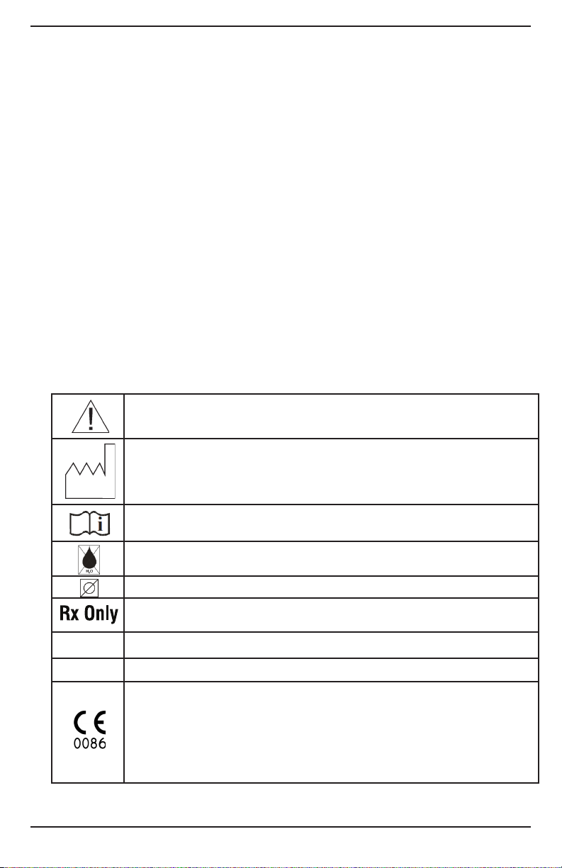
2. EXPLANATION OF SYMBOLS
SN
REF
Refer to manual for proper method of operation
Date of Manufacture
Refer to manual for proper method of operation
Warning: Condensed water in air supply can cause malfunction of this
device
Warning: Do not obstruct alarm or bleed holes in the bottom of this device
Caution: Federal law restricts this device to sale by or on the order of a
licenced healthcare practitioner
Serial Number
Catalog Number
The CE Mark displayed on this product signies that this device is in compliance
with the European Medical Devices Directive (Council Directive 93/42/EEC). As
a perquisite for the CE mark, Bio-Med Devices operated under an ISO 13485
compliant quality system (covering the design and manufacture of medical devices). The four-digit code underlying the CE mark (0086) pertains to Bio-Med’s
Notied Body, the British Standards Institute, whose function is to investigate
and attest to the validity of CE-mark claims.
56700-0494-200 (Rev.6) 04-2018
Page 6

3. SPECIFICATIONS
Congurations available deliver accurate FIO2 mixtures from one (1) up to three (3) outlet
ports allowing the blender to power three items at once. Several ow ranges are available.
They can be used with ventilators, nasal cannulas, mask CPAP and resuscitation bags.
The Low Flow version of the blender provides ows from 3 to 30 LPM with no gas bleed.
The high/low blender provides ow from 15-20 LPM with no gas bleed. MRI conditional
versions that are made entirely of non-magnetic materials are also available.
Device-Specic Standards: Complies with ISO 11195 : 1995.
Oxygen % Range: 21 to 100%
Oxygen % Accuracy: ±3% of full scale
Supply Pressure: Both supplies within range of 30-75 PSI (207-517 kPa) and Air &
oxygen must be within 10 psi (69 kPa) of each other. *Do not use on a patient or with a
ventilator outside of this range.
*Blender performance with supply pressures below range (0-30 PSI / 0-207 kPa)
cannot be predicted. Due to low output pressure, it will not be able to adequately
drive a ventilator. Not for patient use.
Blender performance with supply pressures above range (75-112.5 PSI / 517775 kPa) with supplies balanced, available output ows and oxygen percentages
will remain consistent with specication. Output pressures will be proportionally
higher and may damage the ventilator. Not for patient use.
Maximum Flow: ≥120 LPM High/Low Flow Blender (≥30 LPM, Low Flow Blender) @ 60%
setting & 50 PSI (345 kPa) inlet pressures.
Standard Flow Ranges: refer to table in Section 4.
Custom Conguration Flow Ranges: refer to addendum and table in Section 4.
Pressure Drop: <6 psi (42 kPa) at 50 psi (345 kPa) inlet pressure and 40 LPM ow
(10 LPM, Low Flow blender).
Low Supply Alarm: as described in Section 4.
Alarm/Bypass Reset: when inlet gas pressure differential is ≥6 psi (42 kPa).
Alarm Intensity: 80 dB at 1 foot.
Input ttings: Oxygen female DISS, Air male DISS. (NIST available)
Output Fitting(s): Male DISS, oxygen type.
Dimensions: Height 3 1/2” (8.9 cm)
Width 2 1/4” (5.7 cm)
Depth 2 7/8” (7.3 cm)
Weight: 2.35 lbs (1.07 kg)- basic low ow model with plastic chamber plates
or 3.15 lbs (1.43 kg)- basic low ow model with aluminum chamber plates
No electronics incorporated.
Reverse Gas Flow: From either gas inlet to the other is zero (complies with clause 6 of
ISO 11195).
6 6700-0494-200 (Rev.6) 04-2018
Page 7

4. INTRODUCTION AND OPERATION
This Air/Oxygen Blender is a precision proportioning device for mixing medical grade air
and oxygen to any concentration from 21% to 100% oxygen and delivering it to a variety
of respiratory care devices. The blender uses source air and oxygen at a pressure of 50
psi (345 kPa) connected to two D.I.S.S. ttings on the bottom of the blender. Each tting
has a built-in 30 micron particulate lter. The gas source passes through a duckbill check
valve which prevents reverse gas ows from either source.
The blender uses a double stage balancing system with the gas entering into the
rst stage to equalize the operating pressure of the gas sources before entering the
proportioning stage.
The gases then ow into the proportioning stage where they are mixed to the percentage
dialed in on the front panel knob. This stage has a double-ended valve with valve seats
on either end. Each one of these valve seats controls the passage of the air or oxygen to
the outlet of the blender.
Many different congurations of blenders and output ports are available. The model
number can be found on the back of the blender. See ‘Model Identier’ on page 2 or use
the front of the blender to identify which row to use in the table below to determine its ow
range. The blender will be Low Flow or High/Low Flow. The ow limitations listed below
apply, regardless of what is attached to the port. If the bleed is active, the “ows with
bleed” applies to all output ports. Conversely, if the bleed is inactive, the “ows without
bleed” applies to all ports.
NOTE: The upper ow limit is the total ow that the blender will pass, not the
limit per port. As an example, if 30 LPM is passing through any one port on a
Low Flow blender, then no other port should be used as 30 LPM is the upper
ow limit for this blender.
The bleed referred to in the table and elsewhere in this manual is activated in one of
three ways depending on what is on the right side of the blender. If there is a DISS tting,
attaching a device to this tting will turn on the bleed1. If there is a knob, setting it to the
“<” position will turn on the bleed (see Addendum 1). If there is a owmeter on a switch
mounted here, rotating it to its vertical position will turn on the bleed (see Addendum 2). If
none of these options are available on the right side, then the bleed cannot be turned on
and off.
FLOW TABLE:
Model Flow Range without Bleed Flow Range with Bleed
Low Flow 3-30 lpm 0-30 lpm (3 lpm Bleed)
High/Low Flow 15-120 lpm (No Bleed) 2-108 lpm (10-12 Bleed)
1
WARNING: Some special order blenders may not have a
bleed when using the right DISS outlet. When this is the
case, the ow specications for without bleed apply.
Note: The NEO2 Blend conforms to the Low Flow conguration with ow
limited by the owmeters. Refer to Addendum 2 in the beginning of
this manual.
76700-0494-200 (Rev.6) 04-2018
Page 8

The blender has an audible built in alarm which detects if either of the gas sources
changed by more than 20 psi (138 kPa) from the other. The alarm will warn the user that
they are running out of one of the gas sources or that there is a severe pressure drop in
one source. If both gas sources drop or increase together such that a 20 psi (138 kPa)
difference cannot be detected, no alarm will sound. If the blender is connected but not
being used and a 20 psi (138 kPa) difference in gas sources develops, the blender will not
alarm.
The blender alarm/bypass function will provide > 90 LPM (the full 30 LPM, Low Flow
Blender) upon the loss of air or oxygen, if the remaining gas is at 50 psi (345 kPa)
5. SETTING UP THE BLENDER
The blender can be either pole, wall, or rail-mounted for easy use and for any desired
application. The inlet ttings are located on the bottom of the blender and conform to
Diameter Index Safety System (D.I.S.S.) and air and oxygen connections cannot be
reversed. Connect an air high pressure hose to the air tting and an oxygen high pressure
hose to the oxygen tting on the bottom of the blender. It is recommended that an air inlet
water trap be used between the air hose and inlet tting to prevent moisture from entering
the blender.
The primary outlet (see Addendum 1) on the bottom of the standard high ow blender
is appropriate for high ow situations, as with most ventalators requiring ows up to 120
LPM. Flows of less than 15 LPM (3 LPM, Low Flow blender) require the right side outlet
(bleed knob or bleed switch). If both outlets are used simultaneously, neither one will
deliver its maximum ow.
6. TESTING THE BLENDER
The following checks should be performed before placing the blender into service.
Note: If the blender does not pass these checks do not place the
unit into service; call your dealer or service representative.
• Connect the 50 psi (345 kPa) air and oxygen sources to the appropriate ttings and
set the blender to 60% (the alarm should not activate).
• Check to ensure that the oxygen concentration is actually 60% by using a calibrated
oxygen analyzer (conforming with ISO 7767).
• Disconnect the oxygen source from the blender and listen for the audible alarm. Once
it alarms, reconnect the oxygen to stop the alarm.
• Verify the oxygen concentration again.
• Disconnect the air source from the blender and listen for the audible alarm
• Once it alarms, reconnect the air and verify the oxygen concentration again.
8 6700-0494-200 (Rev.6) 04-2018
Page 9

7. USING THE BLENDER
• Connect the gas outlet of the blender either directly or via a high pressure hose to the
ventilator or other equipment with which it is being used.
• Set the control on the front panel to the desired oxygen concentration.
• Turn on the 50 psi (345 kPa) air and oxygen sources.
• Set the controls on the ventilator or equipment being used.
• Use a calibrated oxygen analyzer to check the accuracy of the patient gas.
• When changing oxygen concentration, wait sixty seconds (equilibration time) before
checking it against the analyzer.
96700-0494-200 (Rev.6) 04-2018
Page 10

8. TROUBLE SHOOTING GUIDE
PROBLEM CAUSE OF PROBLEM TO SOLVE PROBLEM
OXYGEN ANALYZER
DOESN'T AGREE WITH
SETTING OF BLENDER
BLENDER ALARMING AIR AND OXYGEN
THE ONLY TIME
THE BLENDER
IS ACCURATE IS
WHEN THE SOURCE
PRESSURES ARE
EXACTLY THE SAME
ANALYZER OUT OF
CALIBRATION
BLENDER OUT OF
CALIBRATION
DIRTY GAS SUPPLY CALL SERVICE
BLEED ON BOTTOM OF
BLENDER IS RESTRICTED
AIR IS FLOWING INTO
PIECE OF EQUIPMENT
BEING USED AND
DILUTING
CONCENTRATION
SOURCE PRESSURES
HAVE GREATER THAN 20
PSI (138 kPa)
DIFFERENTIAL
ALARM SYSTEM IS OUT
OF CALIBRATION
DIRTY GAS IS
CONTAMINATING ALARM
SYSTEM
PRESSURE BALANCE
CHAMBER NOT WORKING
PROPERLY
CALIBRATE OXYGEN
ANALYZER
CALL SERVICE
DEPARTMENT
DEPARTMENT
CALL SERVICE
DEPARTMENT
CORRECT SITUATION
BY STOPPING THE
FLOW OF AIR
BRING THE SOURCE
PRESSURES WITHIN
THE 20 PSI (138 kPa)
RANGE
CALL SERVICE
DEPARTMENT
CALL SERVICE
DEPARTMENT
CALL SERVICE
DEPARTMENT
10 6700-0494-200 (Rev.6) 04-2018
Page 11

9. BLENDER WARRANTY
The warranty lasts for one year from date of purchase. This warranty covers parts and
labor. Shipping costs are covered up to six months from the date of purchase. This
warranty is limited to defects in parts and workmanship and does not cover incidents due
to misuse or abuse of the product.
All service must be performed by authorized service personnel. The manufacturer will not
be held responsible for unauthorized service work on any blender.
10. CLEANING INSTRUCTIONS
The blender should only be cleaned by wiping the outside surfaces with alcohol applied to
a tissue or cloth. These blenders should never be sprayed with or immersed in any other
liquid. Be sure not to allow ingress of any appreciable quantity of alcohol into any alarm or
vent holes. Never insert anything into the holes in the alarm cover.
116700-0494-200 (Rev.6) 04-2018
Page 12

®
North America
United States
Customer Service, Distribution Center
Technical Support, Sales and Service
Equipment Service Center
Ohio Medical LLC
1111 Lakeside Drive
Gurnee, IL 60031 USA
P: +1 866 549 6446
F: +1 847 855 6218
www.ohiomedical.com
© 2018 Ohio Medical, LLC. All rights reserved.
This document contains information that is proprietary and condential to Ohio Medical, LLC.Use of
this information is under license from Ohio Medical, LLC. Any use other than that authorized by Ohio
Medical, LLC is prohibited. Ohio Medical and the Ohio Medical logo are registered trademarks of
Ohio Medical, LLC. NFPA is a registered trademark of the National Fire Protection Association.
Manufactured by Bio-Med Devices Inc. distibuted by Ohio Medical LLC.
6700-0494-200 (Rev. 6) 04-2018
 Loading...