

Ohio Medical 263748-C, 263748-B, 263748-E, 263748, 263748-CB Service Manual
...
®
12.1” Touchscreen Master Alarm
Service Manual

Master Alarm Service Manual
Table of Contents
1.0 Responsibilities ............................................................................................................... 3
1.1 Installer Responsibilities ......................................................................................................... 3
1.2 User Responsibilities .............................................................................................................3
2.0 Alarm System Description & Functions ............................................................................. 3
2.1 Description of Basic Alarm & Functions ................................................................................... 3
2.2 Normal, Alarm & Maintenance Mode Condition Views ...............................................................4
2.3 Alarm Banners & Silence Alarm Conditions .............................................................................. 5
2.4 Testing The Alarm .................................................................................................................5
3.0 Installation ...................................................................................................................... 6
3.1 Box Assembly ....................................................................................................................... 6
3.2 Internal View of Master Alarm ................................................................................................. 6
3.3 Installation Instructions Prior To Drywall Plaster .......................................................................7
3.4 Box Wiring & Drywall/Plaster Preparation ................................................................................8
3.5 Instructions After Drywall & Plaster ......................................................................................... 9
3.6 Sensor Connections To Master Alarm Input Terminal(s) ........................................................... 10
3.7 Master Alarm Outputs .......................................................................................................... 12
4.0 Set-Up & Programming .................................................................................................. 13
4.1 Important Electrical Safety Notice Prior To Set-Up .................................................................. 13
4.2 Initial Set-Up ........................................................................................................................14
4.3 Programming, Conguration & Setting Up Alarm Points .......................................................... 15
Alarm Event Log
View All Events & History
View Single AP Log
Information
Test Alarms Points
Other Settings (Display, Factory Reset, Scroll Time)
5.0 Specications ................................................................................................................ 19
6.0 Dimensions ................................................................................................................... 20
7.0 Part Numbers ................................................................................................................ 20
8.0 Battery Replacement ..................................................................................................... 21
9.0 Troubleshooting ............................................................................................................. 22
10.0 Wiring Diagram ........................................................................................................... 23
2
550731 (Rev. 2.1) 11/19

Master Alarm Service Manual
1.0 Responsibilities
Information contained in this Installation and Operation Maintenance Manual pertains to the Ohio Medical Color LCD Touch
Screen Master Alarm (MA) System. The Master Alarm System will operate as described in this manual when operated and
serviced in compliance with the instructions.
1.1 Installer Responsibilities
The alarm should be handled, installed, and tested per the recommended practice as described within this manual.
Should any repair or replacement become necessary, contact Ohio Medical Customer Service (800-448-0770) for original
equipment, replacement parts.
1.2 User Responsibilities
The alarm should be tested and examined periodically according to facility codes. Any parts which are found to be
damaged, corroded, contaminated, etc. should be replaced.
2.0 Alarm System Description & Function
PLEASE NOTE THE FOLLOWING DEFAULT PASSWORD (PW) = “1111”
Note: The unit’s password may be changed anytime. Please contact Ohio Medical Customer Service if your password is forgotten. A Factory
Reset will need to be performed. Upon a Factory Reset, ALL user-customized information/settings will need to be re-entered. Given this,
please store your password in a secure location.
2.1 Description of Basic Alarm & Functions
The alarm is designed to monitor and display the status of up to 30 Alarm Points (APs). When an alarm condition occurs,
a signal is sent to the MA and is displayed on the Liquid Crystal Display (LCD). The unit is capable of relaying alarm
conditions to a Building Management System (BMS) via Dry Contacts, Modbus (or BACnet) or, via Ethernet connection.
Custom alarm labels may be created or chosen in the preprogrammed menu. Examples of alarm conditions include: High/
Low Gas Pressure, Low Vacuum, Manifold Reserve Tank In-Use, High Temperature Shutdown, Reserve Pump Running.
Alarm Events may be viewed/cleared per an individual alarm condition or, collectively as a group. The unit is also
equipped with a Maintenance Mode to permanently silence the audible portion of the alarm until the condition(s) causing
the alarm are xed. Visual Indicators always remain.
Other Key Functions Include:
Universal 100V-240V AC Power Input with Circuit Breaker Protection
Normally Open (N.O.) or Normally Closed (N.C.) alarm point set-up
Alarm Condition Communications (to BMS): Via BACnet, Modbus, Ethernet or Dry Contacts
Up-To 30 Dry Contact Outputs
12.1” Full Color LED Screen; Password Protection
Adjustable Screen-Scroll and Audible Alarm Silence Options
PLEASE READ THIS MANUAL IN ITS ENTIRETY BEFORE PROCEEDING
2.2 Normal Alarm & Maintenance Mode Condition Views
HAZARD OF ELECTRICAL SHOCK OR BURN. TURN OFF POWER
BEFORE WORKING ON THIS EQUIPMENT.
WARNING! SOME EDGES MAY BE SHARP, HANDLE WITH
CAUTION.
550731 (Rev. 2.1) 11/19
3
Master Alarm Service Manual
An AP will be displayed in three different ways:
1. Normal Alarm Condition: An AP will display with a green background and white text (as shown below) if
conditions on the source equipment are operating within normal operating parameters.
2. Alarm Condition: An AP in an alarm condition will display with a red background and white text (as shown
below) if conditions on the source equipment are operating outside normal operation.
3. Maintenance Mode: An AP in maintenance mode will display with a yellow background with black text (as
shown below) …. When the AP is manually placed in Maintenance Mode.
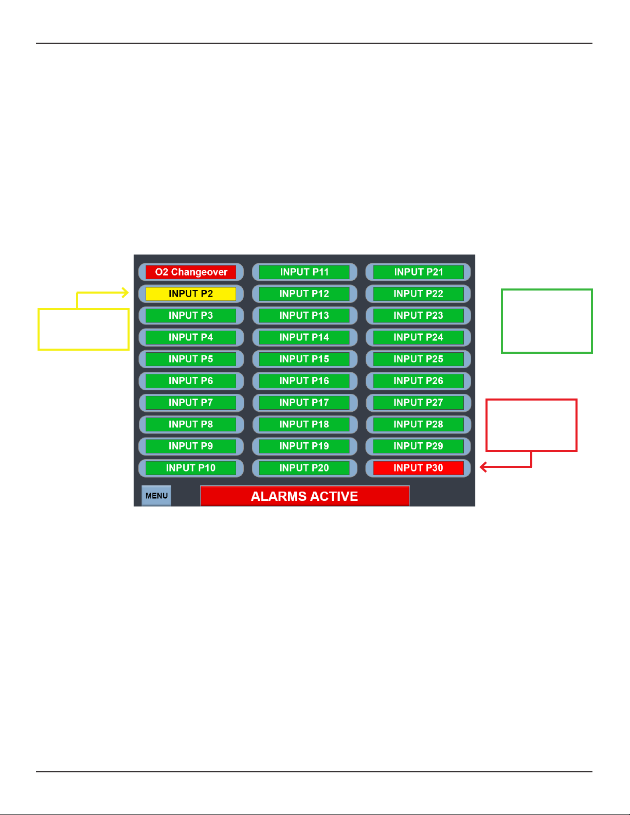
Figure 2.2 Below represents a 30 alarm points (APs) set-up. Two APs are in an alarm condition (red), one is in
maintenance mode (yellow) – with the rest seen as operating normally (green).
[FIGURE 2.2]
1. Normal Alarm
Condition
3. Maintenance Mode
Alarm Point Inputs, such
as INPUT P2
Alarm Point Inputs, such
as INPUT P3 thru INPUT
P29
{
Figure 2.2 Showing Master Alarm Front LCD Touch Screen
Note: Alarm Point Input titles (i.e. O2 Changeover) are customizable by the user.
2. Alarm Condition
Alarm Point Inputs, such
as O2 Changeover and
INPUT P30
4
550731 (Rev. 2.1) 11/19
Master Alarm Service Manual
2.3 Alarm Banners & Silence of Audible Alarm Conditions
The audible alarm will sound under any of the following key conditions:
1. An alarm condition exists for one or more APs.
2. The user adjustable Silence Duration time elapsed and any alarm condition is still present.
3. An alarm input on the MA is congured as Normally Open (N.O.) and the dry contacts for the AP (associated with
the Source Equipment) are congured as Normally Closed (N.C.).
4. An AP is congured, but no actual physical connection to the source equipment is made.
Silencing the Alarm
The Audible Alarm may be silenced in three ways. If the originating cause is not corrected, the following options will not x
the alarm condition.
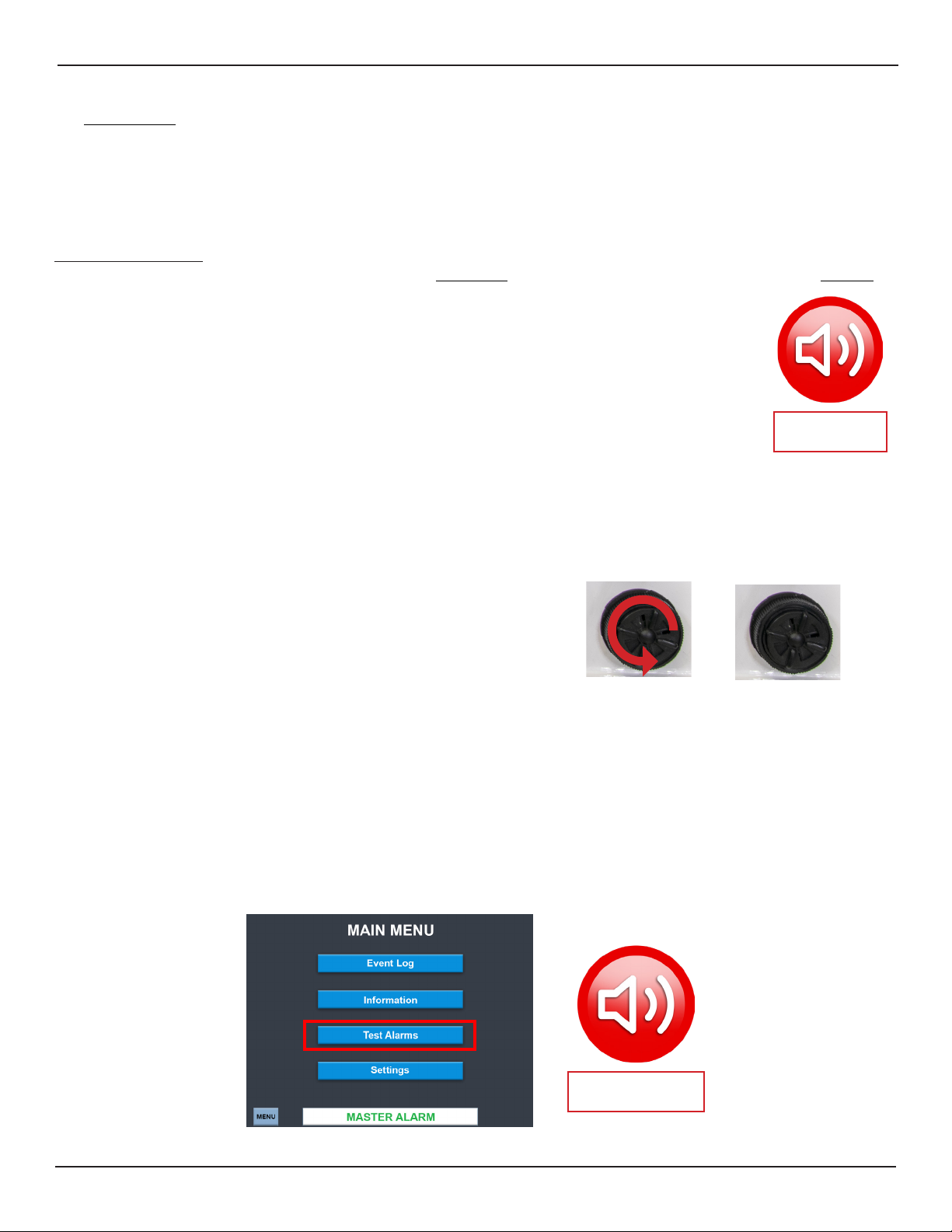
1. Silencing Button: The audible alarm may be temporarily silenced at any time by pressing
the Master Alarm Silencing Button (right) in the lower right portion of
the screen, regardless of the screen. Each time the alarm is silenced,
the user selected silence duration time will restart.
2. Silencing Duration: The default silencing duration time is 5 minutes. The silence duration can
be user set to a maximum of 59 minutes & 59 seconds. Silencing duration
Master Alarm
Silencing Button
must be set greater than 0.
3. Maintenance Mode: Any AP can be manually placed into maintenance mode. This will silence the audible alarm.
Visual alarm indicators remain.
[FIGURE 2.B]
Figure 2.B The volume of the alarm may be adjusted by rotating
the volume control located in the lower right corner of the box
(Reference Figure 3.2).
Bafes fully open for
loudest alarm
Bafes fully closed for
softest alarm
2.4 Testing the Alarm Points (APs) [Visual & Audible]
The MAIN MENU screen contains a Test Alarms button. Press and hold the button for approximately ve seconds. The
alarm will sound for 10 seconds along with red and white ashing visual indicators for all Inputs. See Figure 3.C
[FIGURE 3.C]
550731 (Rev. 2.1) 11/19
Master Alarm
Silencing Button
5
Master Alarm Service Manual
3.0 Installation
The alarm is shipped fully wired, tested and calibrated. For ease of assembly in walls, the alarm is shipped in two sections;
the Box and Front Panel assemblies. The box is installed in the drywall, then the front panel is attached. Finally, box wiring
and sensor inputs/outputs are congured.
3.1 Box Assembly
All sides of the enclosure have knock outs for the power supply
wiring and the input/output terminal blocks. Use a hammer and at
headed screwdriver to punch through the knockouts as shown in
Figure 3.1.
[FIGURE 3.1]
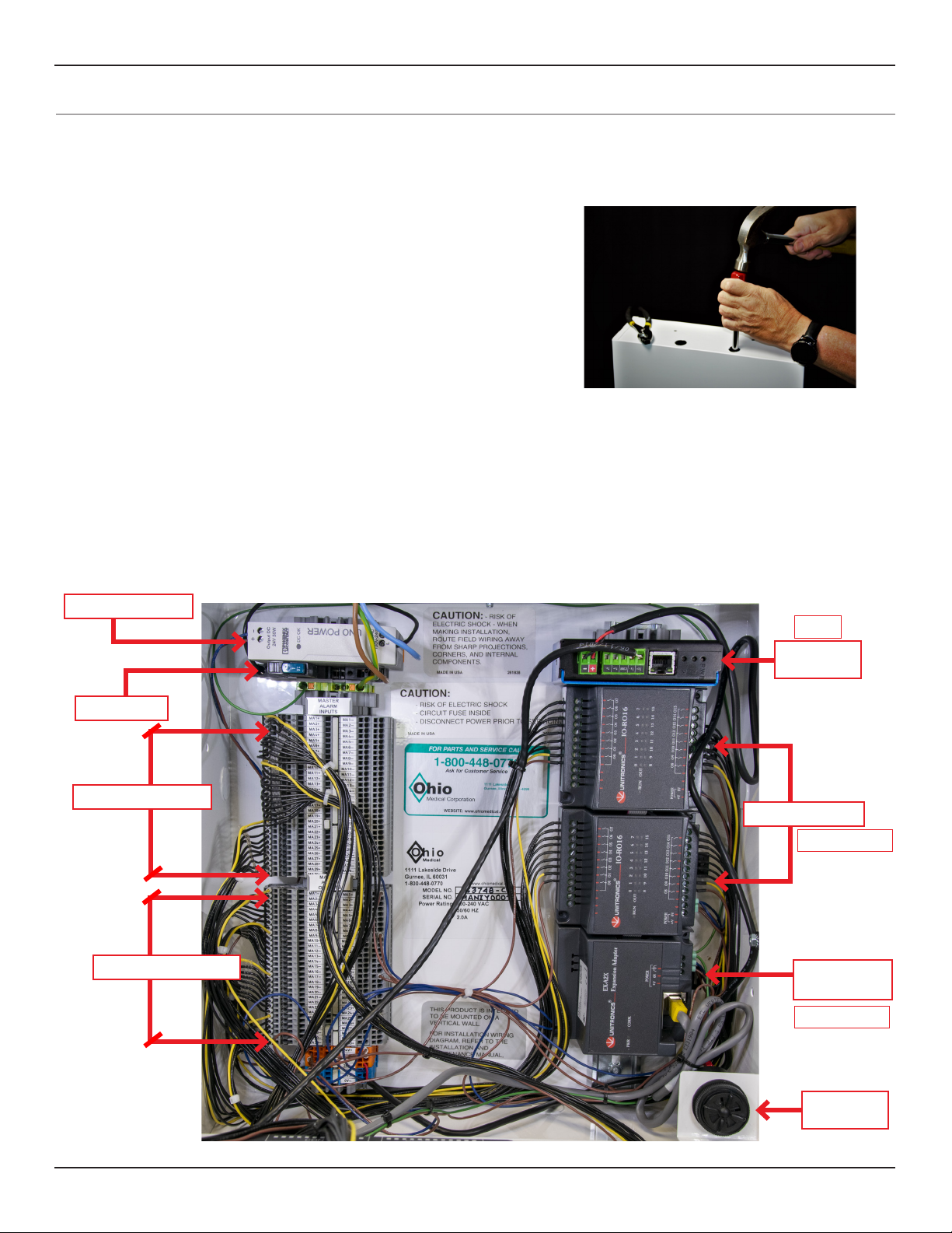
3.2 Internal View of Master Alarm
Primary components integrated within the Box Assembly include what is shown in Figure 3.2 below.
Primary Power Supply
Circuit Breaker
1. Input Terminal Blocks
2. Output Terminal Blocks
[FIGURE 3.2]
Optional
BACnet
Module
IO for Alarm Outputs
Depending on model
Expansion
Adapter
Depending on model
Volume
Control
6
550731 (Rev. 2.1) 11/19
Master Alarm Service Manual
3.3 Installation Instructions Prior to Drywall Plaster
It is important to mount the box between the wall studs at the required height for its intended use. Check all federal, local,
and building codes prior to installation. Adjustable wall-mounted brackets are provided to accommodate for wall thickness
after dry walling, plastering, or other means of wall nishing.
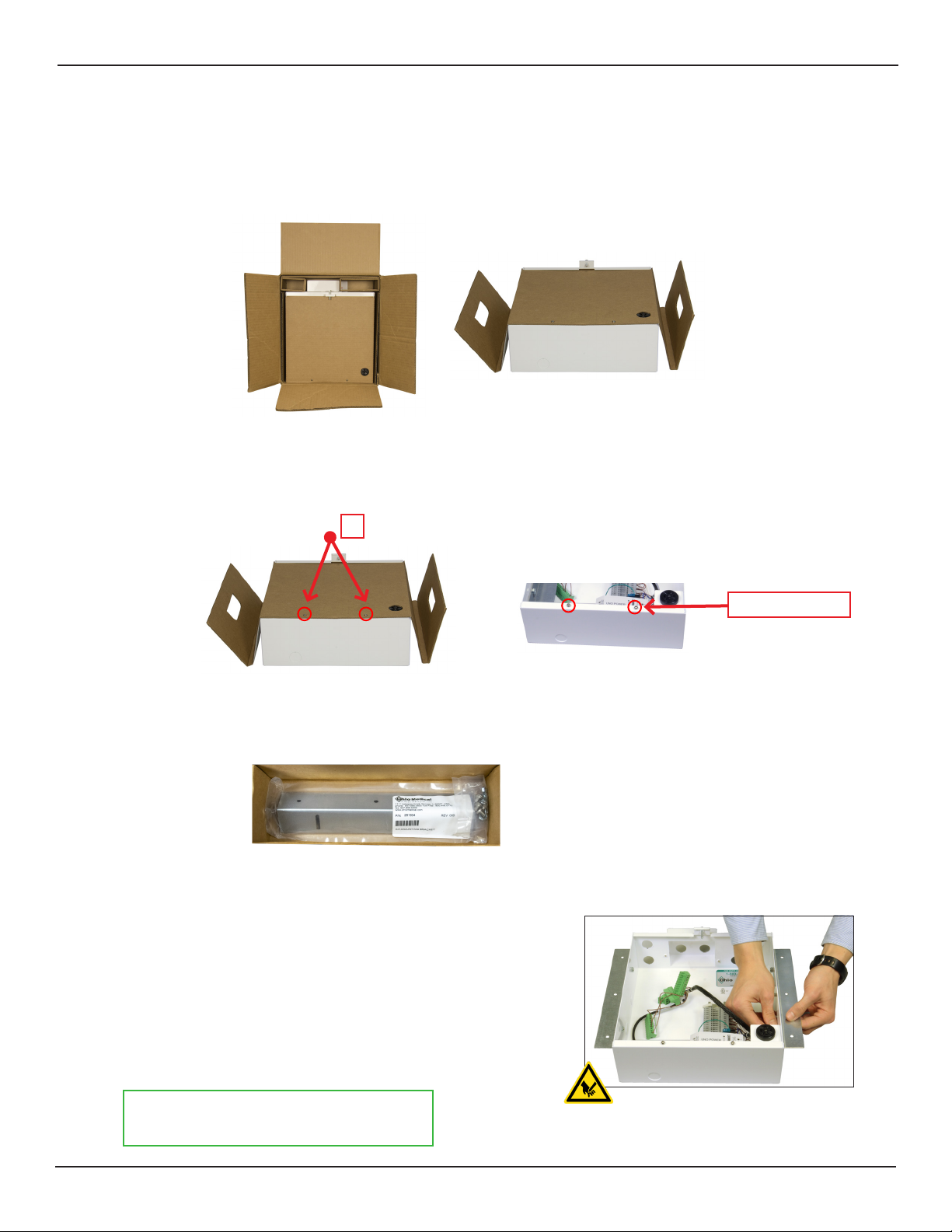
Figure 3.3.1 Remove the metal alarm box assembly from the carton.
[FIGURE 3.3.1]
Figure 3.3.2 Remove the cardboard dust cover from the metal box via the two screws (X). Re-insert the screws into the
box; they will be used later to hold the cardboard cover in place during drywalling/plastering, and ultimately
used for the front panel hinge assembly.
X
[FIGURE 3.3.2]
Reinsert screws
Figure 3.3.3 Remove the metal wall brackets and hardware from the box located inside the primary box the unit has
shipped in.
[FIGURE 3.3.3]
Figure 3.3.4 Install the brackets to the left and right sides of the box.
[FIGURE 3.3.4]
3.3.5 Adjust the brackets so that the front edge of the box assembly
[as shown without the hinged cover] is ush with the nished wall.
3.3.6 Once positioned & square, tighten the hardware securing the
mounting brackets to the alarm box assembly and wall supports.
Do not FULLY tighten hardware at this time.
Keep lightly snug to adjust to wall conditions.
550731 (Rev. 2.1) 11/19
7
Master Alarm Service Manual
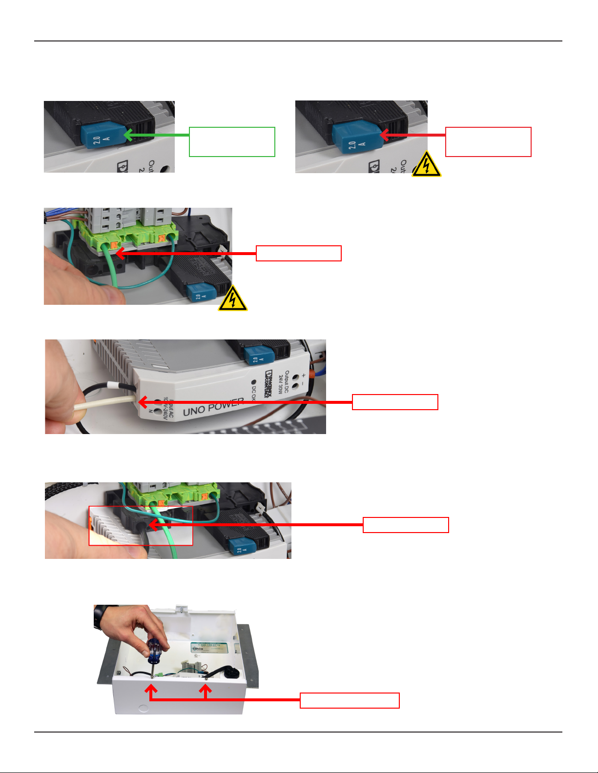
3.4 Box Wiring & Drywall/Plaster Preparation
For safety, the circuit breaker must be in the OFF position prior to electrical connections.
ON Position
pushed and locked in
Strip ½” of insulation and connect the ground wire to the green ground terminal block.
Ground Lead Location
Strip ½” of insulation, connect the neutral lead wire to the power supply terminal labeled “N”.
Neutral Lead Location
OFF Position
fully extended out
Strip the insulation and connect the live lead wire to the circuit breaker.
If not already removed, remove the two screws from the enclosure and set aside.
Note: For clarity, the product is shown removed from the wall.
Remove the Two Screws
8
550731 (Rev. 2.1) 11/19
Live Lead Location
 Loading...