

Page 1
Ohaus CorporationOhaus Corporation
Ohaus Corporation
Ohaus CorporationOhaus Corporation
29 Hanover Road
Florham Park, NJ
07932-0900
INSTRUCTION MANUAL
Balances
1
Page 2
Ohaus Corporation, 29 Hanover Road, Florham P ark, New Jers ey , 07932, USA
Declaration of Conformity We, Ohaus Corporation, declare under our sole responsibility that the balance models listed below marked with
“CE” - are in conformity with the directives and standards mentioned.
Konformitätserkärung Wir, die Ohaus Corporation, erklären in alleiniger Verantwortung, dass die untenstehenden Waagentypen,
gekennzeichnet mit “CE” - mit den genannten Richtlinien und Normen übereinstimmen.
Déclaration de conformité Nous, Ohaus Corporation, déclarons sous notre seule responsabilité, que les types de balance ci-dessous cité munis de la mention «CE» - sont conformes aux directives et aux normes mentionnées ci-après.
Declaración de Conformidad Nosotros, Ohaus Corporation, declaramos bajo responsabilidad exclusiva que los modelos de balanzas
indicados a continuación - con el distintivo ,CE’ - están conformes con las directivas y normas citadas.
Dichiarazione di conformità Noi, Ohaus Corporation, U.S.A, dichiariamo sotto nostra unica responsabilità, che i tipi di bilance specificati di
seguito - contrassegnati con la marcatura “CE” - sono conformi alle direttive e norme citate.
Balance Type/Waagentyp/Type de balance/Modelo de balanza/Tipo di biliancia Navigator
Marked with: Directive Standard
Gekennzeichnet mit: Richtlinie Norm
Munis de la mention: Directive Norme
Con el distintivo: Directiva Norma
Contrassegnati con la Direttiva Norma
Marcatura:
EU 73/23 Low Voltage
EU 73/23 Niederspannung
EU 73/23 Basse tension
EU 73/23 Baja tensión
EU 73/23 Bassa tensione
EU 89/336, 92/31, 93/68
Electromagnetic compatibility
EU 89/336, 92/31, 93/68
Elektromagnetische Verträglichkeit
EU 89/336, 92/31, 93/68
Compatibilité électromagnétique
EU 89/336, 92/31, 93/68
Compatibilidad electromagnética
EU 89/336, 92/31, 93/68
Compatibilità elettromagnetica
IEC1010-1 & EN60950:1992 Safety Regulations
IEC1010-1 & EN60950:1992 Sicherheitsbestimmungen
IEC1010-1 & EN60950:1992 Consignes de sécurité
IEC1010-1 & EN60950:1992 Disposiciones sobre seguridad
IEC1010-1 & EN60950:1992 Prescrizioni . di sicurezza
EN55022:1987 Emissions
EN50082-1:1992 Immunity
NOTE: The displayed value may be adversely affected under
extreme electromagnetic influences, eg. when using a radio unit in the
immediate vicinity of the device. Once the interference has been
rectified, the product can once again be used for its intended purpose.
EN55022:1987 Funkstörungen
EN50082-1:1992 Immunität
Hinweis: Unter extremen elektromagnetischen Einflüssen z.B. bei
Betreiben eines Funkgerätes in unmittelbarer Nähe des Gerätes kann
eine Beeinflussung des Anzeigewertes verusacht werden. Nach Ende
des Störeinflusses ist das Produkt wieder bestimmungsgemäss
benutzbar.
EN55022:Emissions parasites
EN50082-1:1992 Immunité
Remarque: Dans des conditions d'influences électromagnètiques
extrêmes, par exemple en cas d'exploitation d'un appareil radio à
proximité immédiate de l'appareil la valeur d'affichage risque d'être
influencée. Une fois que l'influence parasite est terminée, le produit
peut être de nouveau utilisé de manière conforme aux prescriptions.
EN55022:1987 Radiointerferencias
EN50082-1:1992 Inmunidad
Nota: Bajo influencias electromagnèticas extremas, p.ej. cuando
funciona una radio en las inmediaciones del aparato, se pueden
alterar los valores del display. Cuando concluye el efecto perturbador,
el producto puede ser utilizado de nuevo, de acuerdo con lo
estipulado.
EN55022:1987 Radiointerferenze
EN50082-1:1992 Immunità
Nota: ll valore visualizzato può essere influenzato negativamente dalla
presenza di forti interferenze elettromagnetiche, per esempio quando
viene usata una radio in prossimità della bilancia. Eliminata la fonte
dell'interferenza, il prodotto può essere nuovamente utilizzato per le
funzioni cui è preposto.
James Ohaus
President
2
Page 3

ISO 9001 Certificate for Ohaus Corporation.
BVQI, and was awarded the ISO 9001 certificate. This certifies that Ohaus Corporation, USA, has a quality system that conforms with the international standards for
quality management and quality assurance (ISO 9000 series). Repeat audits are carried out by BVQI at intervals to check that the quality system is operated in the proper
manner.
ISO 9001-Zertifikat für Ohaus Corporation.
und erhielt das ISO 9001 Zertifikat. Dieses bescheinigt, dass Ohaus Corporation, USA über ein Qualitätssystem verfügt, welches den internationalen Normen für
Qualitätsmanagement und Qualitätssicherung (ISO 9000er-Reihe) entspricht. Anlässlich von Wiederhol-Audits durch das BVQI wird periodisch überprüft, ob das
Qualitätssystem zweckmässig gehandhabt wird.
Certificat ISO 9000 pour Ohaus Corporation.
et a obtenu le certificat, degré ISO 9001. Celui-ci atteste que Ohaus Corporation, USA, dispose d’un système qualité correspondant aux normes internationales pour
la gestion de la qualité et pour I’assurance qualité (degré ISO 9000). Des audits réguliers effectués par la BVQI vérifient si le système qualité est appliqué de facon
appropriée.
Certificado ISO 9001 para Ohaus Corporation.
(BVQI) y ha obtenido el certificado ISO 9001. Esto acredita que Ohaus Corporation, USA, dispone de un sistema de calidad que cumple las normas internacionales para
gestión y garantfa de calidad (ISO serie 9000). Con ocasión de las inspecciones de repetibilidad por parte de la BVQI, se comprueba periódicamente si el sistema de
calidad se manipula de forma correcta.
Certificato ISO 9001 per la Ohaus Corporation.
1994 dall Bureau V eritas Quality International BVQI, e così fomice la dimostrazione che il suo sistema die Garanzia Qualità soddisfa i massimi requisite. ll sistema della
garanzia della qualità Ohaus Corporation viene verificato periodicamente dall BVQI, dando cosi evidenza di.
Ohaus Corporation, USA, was examined and ev aluated in 1994 by the Bureau V eritas Quality International,
Die Firma Ohaus Corporation, USA, wurde 1994 durch das Bureau V eritas Quality International BVQI geprüft,
La société Ohaus Corporation, USA, a été contrôlée en 1994 par Bureau V eritas Quality International BVQI
La firma Ohaus Corporation, USA, ha sido inspeccionada por la Bureau V eritas Quality International
ll sistema di garanzia della qualità della Società Ohaus Corporation, USA è certificato ISO 9001 sin dal
NOTE: THIS EQUIPMENT HAS BEEN TESTED AND FOUND T O COMPLY WITH THE LIMITS FOR A CLASS B
DIGIT AL DEVICE, PURSU ANT TO PART 15 OF THE FCC R ULES.
THESE LIMITS ARE DESIGNED T O PRO VIDE REASONABLE PRO TECTION AGAINST HARMFUL INTERFERENCE
WHEN THE EQUIPMENT IS OPERATED IN A COMMERCIAL ENVIRONMENT . THIS EQUIPMENT GENERATES,
USES, AND CAN RADIA TE RADIO FREQUENCY ENERGY AND, IF NOT INSTALLED AND USED IN ACCORDANCE
WITH THE INSTR UCTION MANUAL, MAY CAUSE HARMFUL INTERFERENCE T O RADIO COMMUNICA TIONS .
OPERA TION OF THIS EQUIPMENT IN A RESIDENTIAL AREA IS LIKELY T O CA USE HARMFUL INTERFERENCE
IN WHICH CASE THE USER WILL BE REQ UIRED T O CORRECT THE INTERFERENCE AT HIS OWN EXPENSE.
THIS DIGITAL APP ARATUS DOES NOT EXCEED THE CLASS B LIMITS FOR RADIO NOISE EMISSIONS FROM
DIGIT AL APPARA TUS AS SET OUT IN THE INTERFERENCE-CA USING EQUIPMENT STANDARD ENTITLED
“DIGIT AL APPARA TUS”, ICES-003 OF THE DEPARTMENT OF COMMUNICA TIONS.
CET APPAREIL NUMERIQUE RESPECTE LES LIMITES DE BRUITS RADIOELECTRIQUES APPLICABLES A UX
APP AREILS NUMERIQUES DE CLASSE B PRESCRITES D ANS LA NORME SUR LE MATERIEL BROUILLEUR :
“APP AREILS NUMERIQUES”, NMB-003 EDICTEE PAR LE MINISTRE DES COMMUNICA TIONS.
Unauthorized changes or modifications to this equipment are not permitted.
3
Page 4

TABLE OF CONTENTS
OV ERVIEW OF CONTR OLS ........................................................................................................................ 6
OVER VIEW OF DISPLA Y INDICATORS ...................................................................................................... 7
1. GETTING TO KNOW Y OUR BALANCE .............................................................................................................. 8
1.1 Introduction ....................................................................................................................................................... 8
2. INST ALLA TION ................................................................................................................................................... 8
2.1 Unpacking and Checking the Standard Equipment ............................................................................................. 8
2.2 Selecting the Location ........................................................................................................................................ 9
2.3 Installing Wind Shield.......................................................................................................................................... 9
2.4 Installing Subplatform and Pan ........................................................................................................................... 9
2.5 Connecting Power and Comm unications ........................................................................................................... 10
2.6 Leveling the Balance ........................................................................................................................................ 1 0
3. OPERA TING YOUR BALANCE ......................................................................................................................... 11
3.1 The Menu (Basic Settings of the Instrument) ................................................................................................... 1 1
3.2 T urning On the Balance..................................................................................................................................... 12
3.3 Calibr ation ..................................................................................................................................................... 12
3.3.1 Internal Calibration (InCalTM) ................................................................................................................... 14
3.3.2 Calibration message ............................................................................................................................... 15
3.3.3 Calibration Adjust ................................................................................................................................... 16
3.3.4 Span Calibration ..................................................................................................................................... 1 7
3.3.5 User Calibration ...................................................................................................................................... 18
3.3.6 Linearity Calibration ................................................................................................................................ 19
3.3.7 Calibration Test ....................................................................................................................................... 20
3.3.8 Calibration GLP Printout ......................................................................................................................... 21
3.4 Weighing ..................................................................................................................................................... 22
3.5 Percent Weighing .............................................................................................................................................. 2 3
3.6 Parts Counting.................................................................................................................................................. 2 4
3.7 Animal Weighing ............................................................................................................................................... 25
3.8 Checkweighing.................................................................................................................................................. 26
3.9 Printing Data..................................................................................................................................................... 2 7
4. SETTING UP Y OUR BALANCE........................................................................................................................ 28
4.1 Setting Date and Time ...................................................................................................................................... 28
4.2 Readout ..................................................................................................................................................... 29
4
Page 5

TABLE OF CONTENTS (Cont.)
4.3 Good Laboratory Practices (GLP) Data............................................................................................................. 30
4.4 Good Laboratory Practices (GLP) Set .............................................................................................................. 30
4.5 Print ..................................................................................................................................................... 3 1
4.6 RS232 ..................................................................................................................................................... 33
4.7 Mode ..................................................................................................................................................... 34
4.8 Units ..................................................................................................................................................... 3 5
4.9 Global ..................................................................................................................................................... 35
4.10 Custom Unit ............................................................................................................................................... 37
4.11 Auto Shut-Off ............................................................................................................................................. 3 9
4.12 Menu Lock-Out Protection .......................................................................................................................... 40
4.13 Weigh Below............................................................................................................................................... 40
5. CARE AND MAINTENANCE ............................................................................................................................ 41
5.1 Troub leshooting................................................................................................................................................. 41
5.2 RS232 Interface............................................................................................................. ................................... 42
5.3 Error Codes List................................................................................................................................................ 4 5
5.4 Information Messages ...................................................................................................................................... 45
5.5 Service Information......................................................................................................... .................................. 46
5.6 Replacement Parts ........................................................................................................................................... 46
5.7 Accessories ................................................................................................................................................... 46
5.8 Specifications................................................................................................................................................... 4 7
5
Page 6
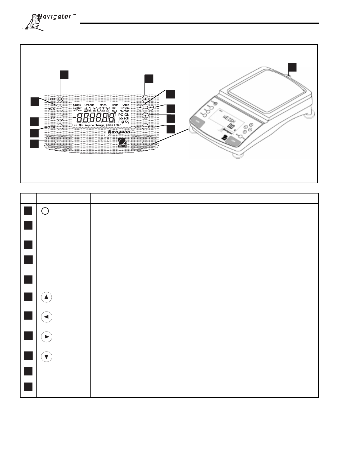
OVERVIEW OF CONTROLS
1
2
11
6
7
8
3
4
5
No. Designation Function
1 I On/Off button Power on/off button.
2 Mode button Selects standard weighing, percent, parts counting, animal weighing and checkweighing
modes.
3 Units button Selects weighing units.
4 Setup button Selects various menus: calibration, date, time, readout, GLP data, GLP set, print,
RS232, mode, units, global, custom and auto shut-off.
5 ->O/T<- button When pressed, performs tare or rezero function.
9
10
6 button When pressed, travels up through menus.
7 button When pressed, travels to the left through menus.
8 button When pressed, travels to the right through menus.
9 button When pressed, travels down through menus.
10 Enter/Print button When in menus, selects item on displa y, otherwise prints data.
11 Leveling indicator Indicates leveling position of the balance.
1
6
Page 7
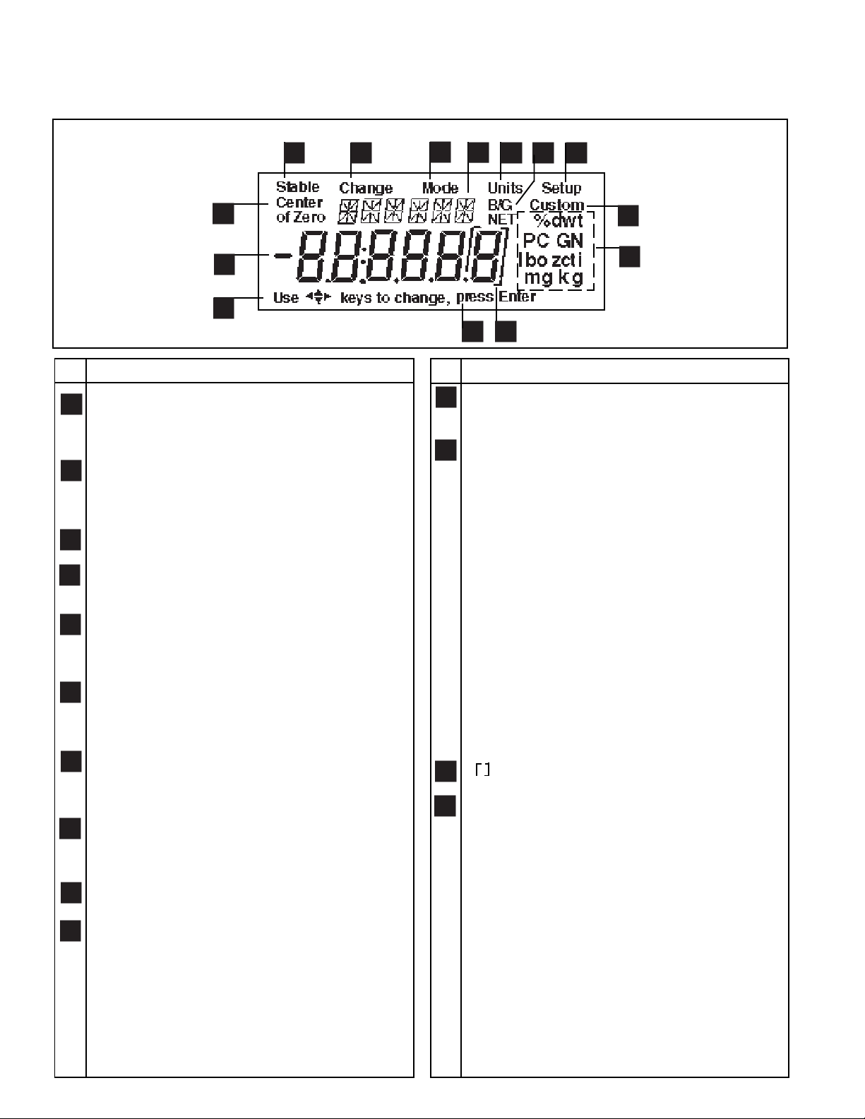
OVERVIEW OF DISPLAY INDICATORS
4
5
9
6
8
7
10
3
2
1
No. Function
1 Use (Pointer Group) key to c hange - used to
prompt the user while navigating through the menu
system.
2 Standard (7) segment numeric characters. Six
characters are available and are used for display-
ing weight values.
3 Center of Zero - Not used
4 Stable - Indicates that the measured value has
become stable.
5 Change - Is displayed together with Mode, Units
or Setup signifying that a change to balance
settings is being performed.
6 Mode - Is displayed when the Mode button is
pressed. Allows the user to know what area of
the balance menu is being addressed.
(14) segment alpha numeric characters. Six
7
characters are used to present features and
functions.
Units - Is displayed when the Units button is
8
pressed. Allows the user to know what area of the
balance menu is being addressed.
9
B/G & NET - Not used
11
12
13
14
No. Function
11 Custom - The user can input a f actor to meet
unique unit measuring applications.
12 Symbols for weighing units and modes, include:
mg - Milligrams
g - Grams
kg - Kilograms
dwt - Penn yweight
ct - Carats
oz - Ounces
oz t - Ounces troy
GN - Grain
t - Taels. Taels are available in three types;
Hong Kong, Singapore , and Taiwan
m - Mommes
lb - Pounds
N - Newton
ti - Tical
% - Percent w eighing
PC - Parts counting
tola - tola (appears on 14 segment display)
13 - Not used
14 press Enter - Used as a prompt to the user to
press the Enter button. The menu item displayed
is accepted/selected.
18
10 Setup - Is displayed when the Setup button is
10
pressed. Allows the user to know what area of the
balance menu is being addressed.
Page 8
1. GETTING TO KNOW YOUR BALANCE
Please read through this section carefully, as it contains important information for safe and economical operation of
your NavigatorTM balance.
1.1Introduction
Thank you for deciding to purchase a Na vigatorTM balance from Ohaus. This v ersatile, portable balance offers a high
level of operating convenience and useful functions to make accurate measurements usually obtained from higher
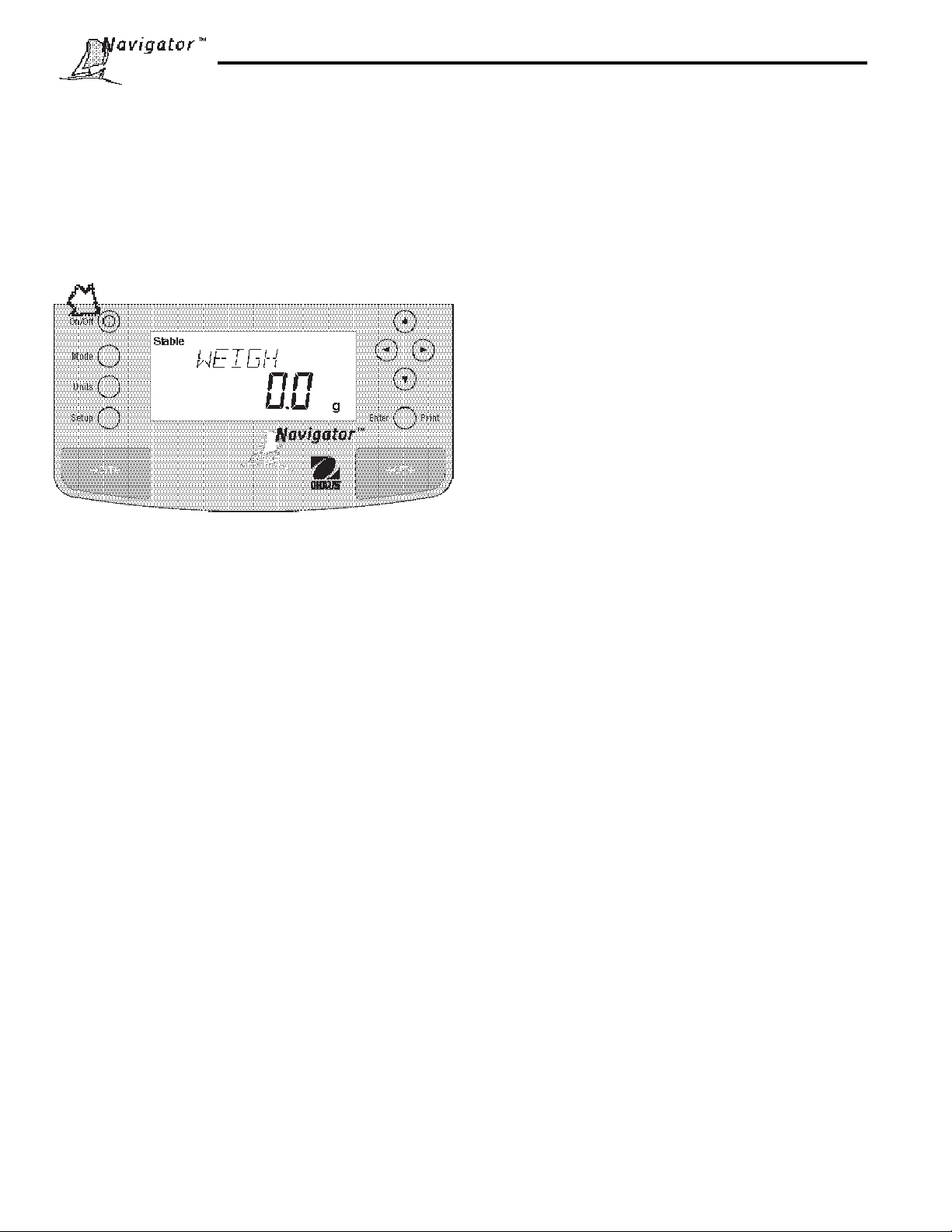
priced laboratory instruments. A custom LCD panel has a large 6 digit, 7 segment display which indicates the weight
value of an item being measured and a 6 character 14 segment display which spells out items selected in the menus.
In addition, the display contains text which indicates the active operating mode of the balance. Arrow indicators in
the display prompt the user as to what panel keys are to be pressed to initiate a change. Built-in RS232 communication is standard on all models and allows communication with printers or computers.
Panel controls are clearly marked as to their function with large zero/tare buttons on either side of the front panel.
Operation and setup of the balance is straightforw ard and easy. Setup is simple with 4 cursor k eys , straightf orw ard
menus, and prompts that easily guide you through the process.
NavigatorTM is designed with contours for easy cleaning and has a sealed front panel and spill gutter to direct liquids
off the balance. For le v eling purposes, all models are equipped with adjustable f eet and a le vel indicator.
Behind your instrument stands OHAUS Corporation, a leading manufacturer of precision w eighing equipment. An
Aftermarket Department with trained instrument technicians is dedicated to provide you with the fastest service
possible in the ev ent your instrument requires servicing. OHA US Corporation also has a Customer Service Department to answer any inquiries regarding applications and accessories.
To ensure you make full use of the possibilities offered by y our NavigatorTM balance, we advise you to read through
these operating instructions very carefully .
2. INSTALLATION
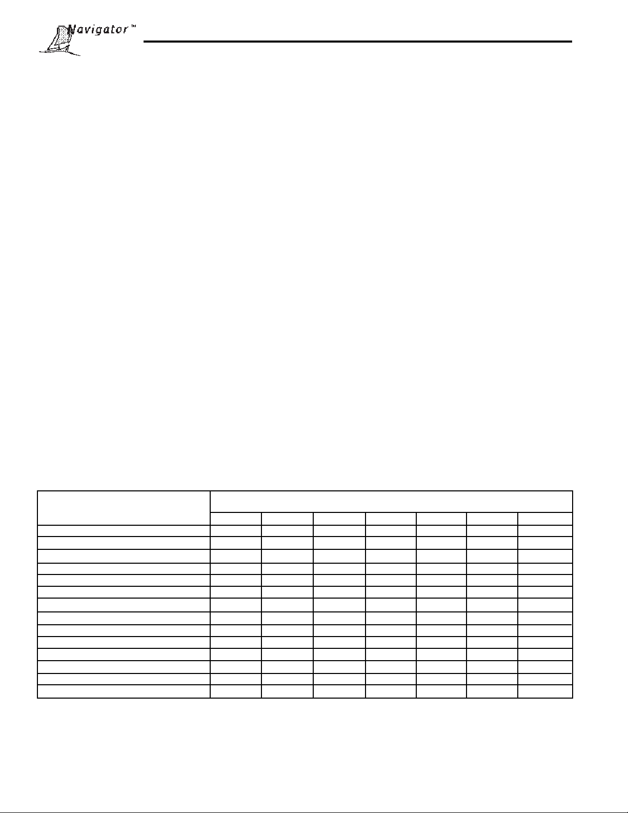
2.1 Unpacking and Checking the Standard Equipment
Open the package and remove the instrument and the accessories. Check the completeness of the delivery . The
following accessories are part of the standard equipment of your new NavigatorTM balance.
Equipment Capacities
••
• Pan 3" Diameter •
••
••
• Pan Support, round 3" •
••
••
• Pan 4.75 Diameter • •
••
••
• Pan Support, round 4.75" • •
••
••
• Pan 6"x5.5" • • • •
••
••
• Pan Support, rectangular • • • •
••
••
• AC Power Adapter • • • • • • •
••
••
• Scoop •
••
••
• Windshield • • • •
••
••
• 30g Calibration mass •
••
••
• Glass Draft shield •
••
••
• Draft shield cover •
••
••
• Instruction Manual • • • • • • •
••
••
• Warranty Card
••
• Remove packing material from the instrument.
32g 210 410g 810g 2100g 4100g 8100g
• • • • • • •
• Check the instrument for transport damage. Immediately inform your Ohaus dealer if you ha v e complaints or
parts are missing.
• Store all parts of the packaging. This packaging guarantees the best possible protection for the transport of your
instrument.
8
Page 9
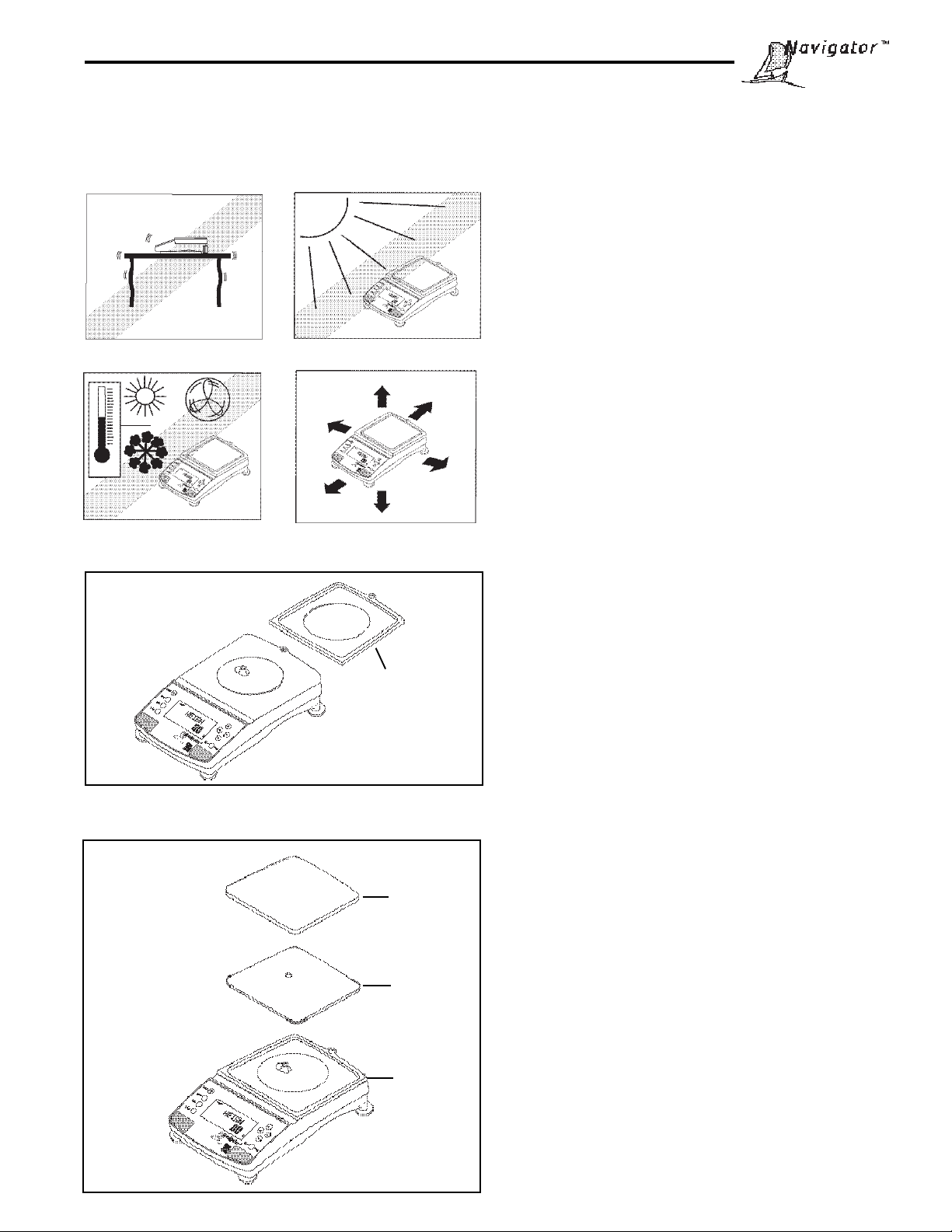
2.2 Selecting the Location
The balance should always be used in an en vironment which is free from e xcessive air currents, corrosives, vibration,
and temperature or humidity extremes. These factors will aff ect displa y ed w eight readings.
DO NOT install the balance:
• Next to open windows or doors causing drafts or
rapid temperature changes.
• Near air conditioning or heat vents.
• Near vibrating, rotating or reciprocating equipment.
• Near magnetic fields or equipment that generates
magnetic fields.
• On an unlevel work surface .
• Allow sufficient space around the instrument for
ease of operation and keep awa y from radiating heat
sources.
2.3 Installing Wind Shield
On 810g to 8100g balances, a wind shield is provided to
reduce the possibility of air currents from disturbing the
pan. When the wind shield is in place, air currents are
deflected up over the pan. Place the wind shield on top
of the balance making sure the small alignment tab is
Wind Shield
located properly on the balance.
2.4 Installing Subplatform and Pan
Pan
Subplatform
Windshield
All balances are supplied with a subplatform and pan.
The subplatform fits through the hole on top of the
balance and rests on a cone assembly which is part of
the measuring load cell.
The bottom of the subplatform contains a slotted keyway
for installation purposes. Place the subplatform in place
aligning the slot with the pin on the cone assembly.
Install the pan on the subplatform. The illustration shows
the rectangular pan.
9
Page 10
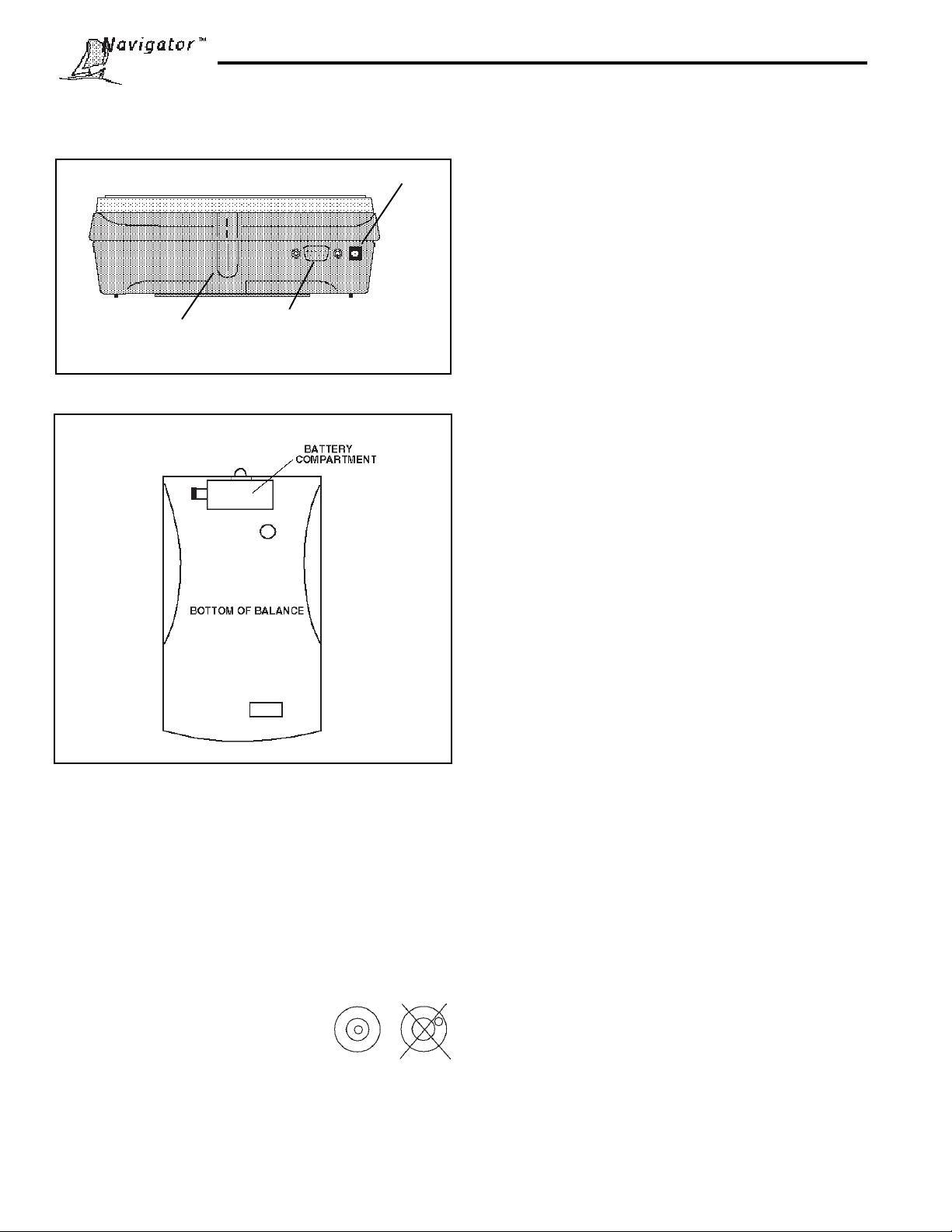
2.5 Connecting Power and
Communications
Security Bracket
Rear of Balance
AC Adapter Connection
RS232 Connector
AC Power Operation
Connect the cord from the AC Adapter supplied to the
connector located at the rear of the balance. Connect the
AC Adapter to an appropriate power source.
Battery Operation
The balance can be operated using 8 AA alkaline batteries (not included). The battery compartment is located on
the bottom of the balance. T o install batteries, proceed as
follows:
• Remove the pan, subplatform, and wind shield.
• T urn the balance over . Do not rest the balance on
the cone.
• Press the tab on the battery cover inward and lift the
cover off.
• Remove the battery holder.
• Install the 8 AA alkaline batteries in the battery holder,
orienting the plus (+) and minus (-) ends as indicated
on the holder.
• Replace the battery holder in the compartment. Make
sure the snap connector is connected.
• Replace the battery cover .
• T urn the balance over and replace the wind shield,
subplatform and pan.
Bottom Vie w of Balance
2.6 Leveling the Balance
Exact horizontal positioning and stable installation are
prerequisites for repeatable results. To compensate small
irregularities or inclinations at the location, the instrument
can be leveled.
For exact horizontal positioning, the balance is equipped
with a level indicator located at rear .
Position the balance in the intended
operating location. Adjust the leveling
feet until the air bubble in the indicator
is centered.
NOTE: The instrument should be leveled each time its
location is changed.
Communication Connections
When an optional printer or computer is going to be used
with the balance, connect an Ohaus RS232 Interface
Cable to the connector at the rear of the balance and the
external device. Refer to paragraph 5.7 Accessories for
cable information and part numbers.
NOTE: A standard RS232 cab le cannot be used as the
pin connections are different.
The balance is now ready for operation.
Security Bracket
A security bracket (molded in base) is provided at the
rear of the balance which allows the balance to be
secured by the optional cable and lock accessory.
10
Page 11
3 OPERATING Y OUR BALANCE
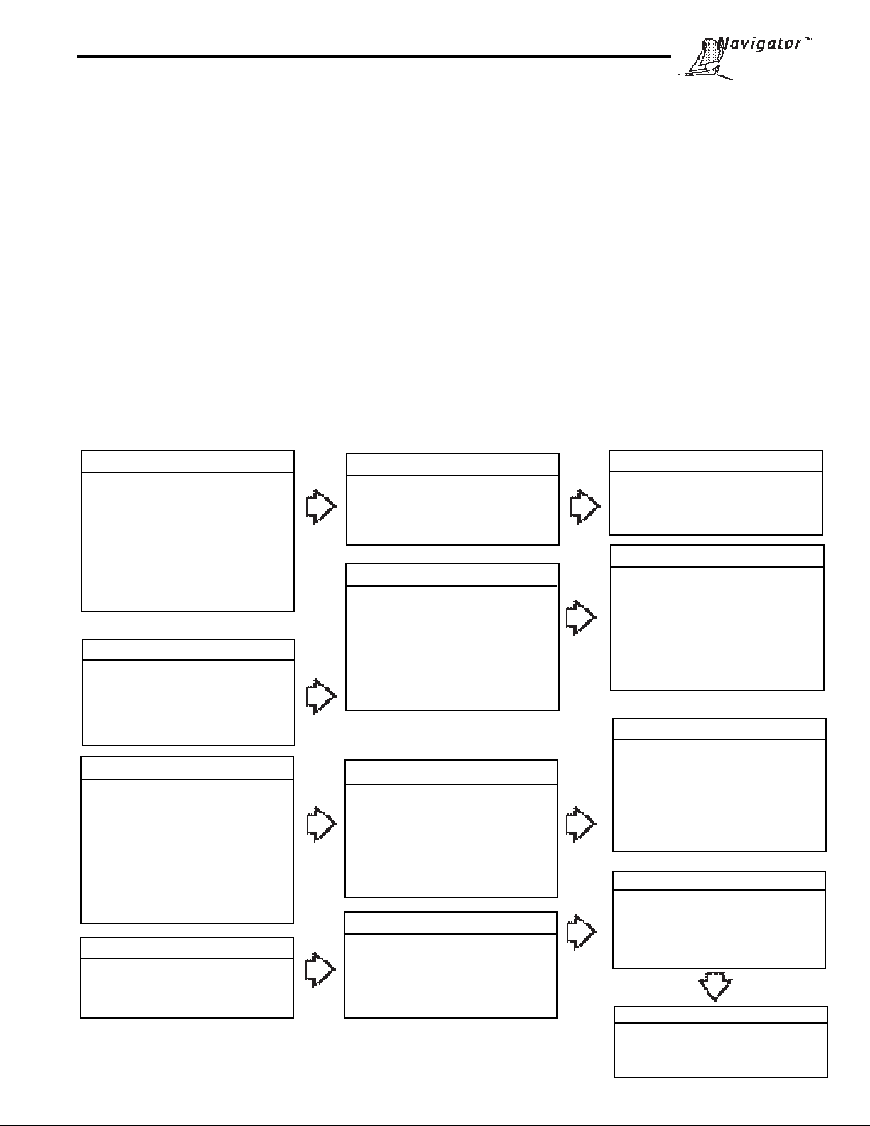
3. 1 The Menu (Basic Settings of the Instrument)
The balance has three basic menus; each is selected by front panel buttons marked Mode, Units and Setup.
Mode Button
The Mode button, when pressed, permits the selection of five weighing modes which are: weigh, percent, count, animal
weighing and checkweigh. These modes are controlled by an on or off selection made in the Setup menu under the
Mode menu.
Units Button
The Units button, when pressed, allows you to select or change units.
Setup Button
The Setup button, when pressed, allows entry into menus which allow you to set the balance for specific operating
parameters. Each of the menus contain settings which are user selectab le. The tables below illustr ates the various
menus and the functions which are selectable. The items shown on the menu, which are bolded, are the factory default
settings. If the Setup menu is not entered, the balance would function in the basic manner shown by the various
settings which are bolded. The setup menus shown belo w are arranged in the order as displayed in the balance .
ST ART
CAL (CALIBRATION)
InCalTM Calibration (No Lock)*
Span Calibration
User Calibration
Linearity Calibration
Calibration Test (No Lock)
Calibration Now ON/OFF
Calibration Adj ± 100 (0)
Lock ON/OFF
Exit
*(If option is installed)
READOUT
Stable .5d, 1d, 2d, 5d
Auto 0 OFF, .5d, 1d, 3d
Filter -0-, -1-, -2-, -3-
Lock ON / OFF
Exit
PRINT
Auto Print OFF, Cont, Inter, On Stb
Interval Enter 1 seconds
Stable ON/OFF
Numeric ON/OFF
GLP Con ON/OFF
GLP T ar ON/OFF
Reference ON/ OFF
Lock ON / OFF
Exit
UNITS
Units (grams only) ON/OFF
Lock ON/OFF
Exit
SETUP SUBMENUS
DATE
Type m/d/y, dMy, yMd, Myd,ydM,
or dyM
Set
Exit
GLP DATA
User Number Enter 6 digits
Project Number Enter 6 digits
Lock ON/OFF
Exit
RS232
Power ON/OFF (Battery mode only)
Baud 300, 1200, 2400, 4800, 9600
Parity None, -E-, -Odd-, -0-, -1Data 7,8
Stop 1, 2
Lock ON/OFF
Exit
GLOBAL
List NO/YES
Reset NO/YES
Version Software No.
Lock ON/OFF
Exit
TIME
Type 12 Hour/24 Hour
Set Time
Adjust Enter xx seconds
Exit
GLP SET
Time ON/OFF
Balance ID ON/OFF
User Number ON/OFF
Project Number ON/OFF
Difference ON/OFF
Name ON/OFF
Lock ON/OFF
Exit
MODE
Weigh ON/OFF
Percent ON/OFF
Count ON/OFF
Animal ON/OFF
Checkweigh ON/OFF
Lock ON/OFF
Exit
CUSTOM
Factor Enter 6 digits
Exponent 3 , 2, 1, 0, -1, -2, -3
LSD .5, 1, 2, 5, 10, 100
Lock ON/OFF
Exit
AUTO SHUT OFF
Timer 0 - 60 minutes
Lock ON/OFF
Exit
11
Page 12
3. 2 Turning On the Balance
The balance is ready to operate after the installation procedures are performed. When the balance is first turned on
and it completes its checks, it can be used to weigh or tare materials without setting the menus.
It is recommended that you read this manual carefully and set the balance to operate for your specific applications
using the procedures in Chapter 4 Setting up Your Balance and calibrate the balance before using.
In this section, you will enter the menu for the first time. Do not worry if you are unfamiliar with the function of the
buttons on the panel, the display provides the necessary coaching as you go along.
Power On/Off
To turn the balance ON, press the ON/OFF button (circled
button with an I inside) located at the upper left-hand
corner of the panel once. To turn OFF , press b utton
again.
NOTE: If the balance has been battery operated for a
long period of time, and the batteries are low, the balance
displays LO WB A T. Turn the balance OFF. Remo ve the
batteries and replace.
Stabilization
Before initially using the balance, allow time for it to
adjust to its new environment. Recommended warm up
period is 5 minutes.
Calibration
Refer to paragraph 3.3 and calibrate the balance before
proceeding.
3.3 Calibration
Navigator balances offer a choice of fiv e calibration methods: Internal Calibration (InCALTM), Span Calibration, User
Calibration, Linearity Calibration, and CalTestTM.
•
•
• User
• Linearity
• Cal Test
TM
InCal
Span
- Span calibration ensures that the balance reads correctly within specifications using two
- User calibration is a method where the balance can be calibrated using a mass of known
- Linearity calibration minimizes deviation between actual and displayed weights within the
- Calibration test allows the stored calibration data to be tested against the current mass being
Internal calibration (InCALTM) of the balance is accomplished by an internal mass (If option
is installed). When CAL NOW is selected and set ON, CAL NOW is displayed when the
balance requires calibration. When CAL NO W is set OFF, the message CAL NOW is not
displayed.
weight values: zero and a weight v alue at 50% of full capacity and or 100% of the balance’ s
full capacity.
value and entering that numeric value into the balance.
balance’s weighing range . Three weight v alues are used: zero , a weight value at midpoint of
the balance's weighing range, and a weight value at or near the balance’ s specified capacity.
used for the test.
•
Lock
- Can be set on or off. When set on, Span, User and Linearity calibration are locked out and
cannot be used.
12
Page 13
3.3 Calibration (Cont.)
Calibration Menu Protection
NOTES:
• Calibration may be locked out to prevent unauthorized
personnel from changing calibration. If calibration has been
locked out, you can only access Cal Test.
• To lock out calibration menu, after calibration, refer to the
section titled Menu Lock-Out Protection, paragraph 4.12.
Calibration Masses
Before beginning calibration, make sure masses are
available. If you begin calibration and realize calibration
masses are not availab le , e xit the men u. The balance will
retain previously stored calibration data. Calibration should
be performed as necessary to ensure accurate weighing.
Masses required to perform the procedures are listed in
the adjacent table and are available as accessories.
NOTE:
Any of the calibration modes can be terminated
time
by pressing either the Mode, Units or Setup buttons.
at any
CALIBRA TION MASSES
LINEARITY SPAN ONLY
CAPACITY MASSES MASSES
32g 10g and 30g 30g
210g 100g and 200g 100g or 200g
410g 200g and 400g 200g or 400g
810g 400g and 800g 400g or 800g
2100g 1000g and 2000g 1000g or 2000g
4100g 2000g and 400g 2000g or 4000g
8100g 4000g and 8000g 4000g or 8000g
It is recommended that masses meet or exceed ASTM
Class 4 Tolerance. Models 410g and 4100g use Class
2. Calibration masses are available as accessories.
13
Page 14
3.3.1Internal Calibration (InCALTM)
On NavigatorTM balances equipped with the InCalTM feature, calibration can be accomplished using the internal calibration mass. InCalTM requires use of the AC adapter supplied with the balance. When the balance requires calibration, a
screen prompt of CAL NOW appears. This display can be turned off as described under Calibration Message. Also , a
software feature is incorporated which permits the internal calibration mass to be adjusted by +100 divisions. The
adjust feature is described under Calibration Adjust. Internal calibration can be performed at any time providing the
balance has warmed up to operating temperature.
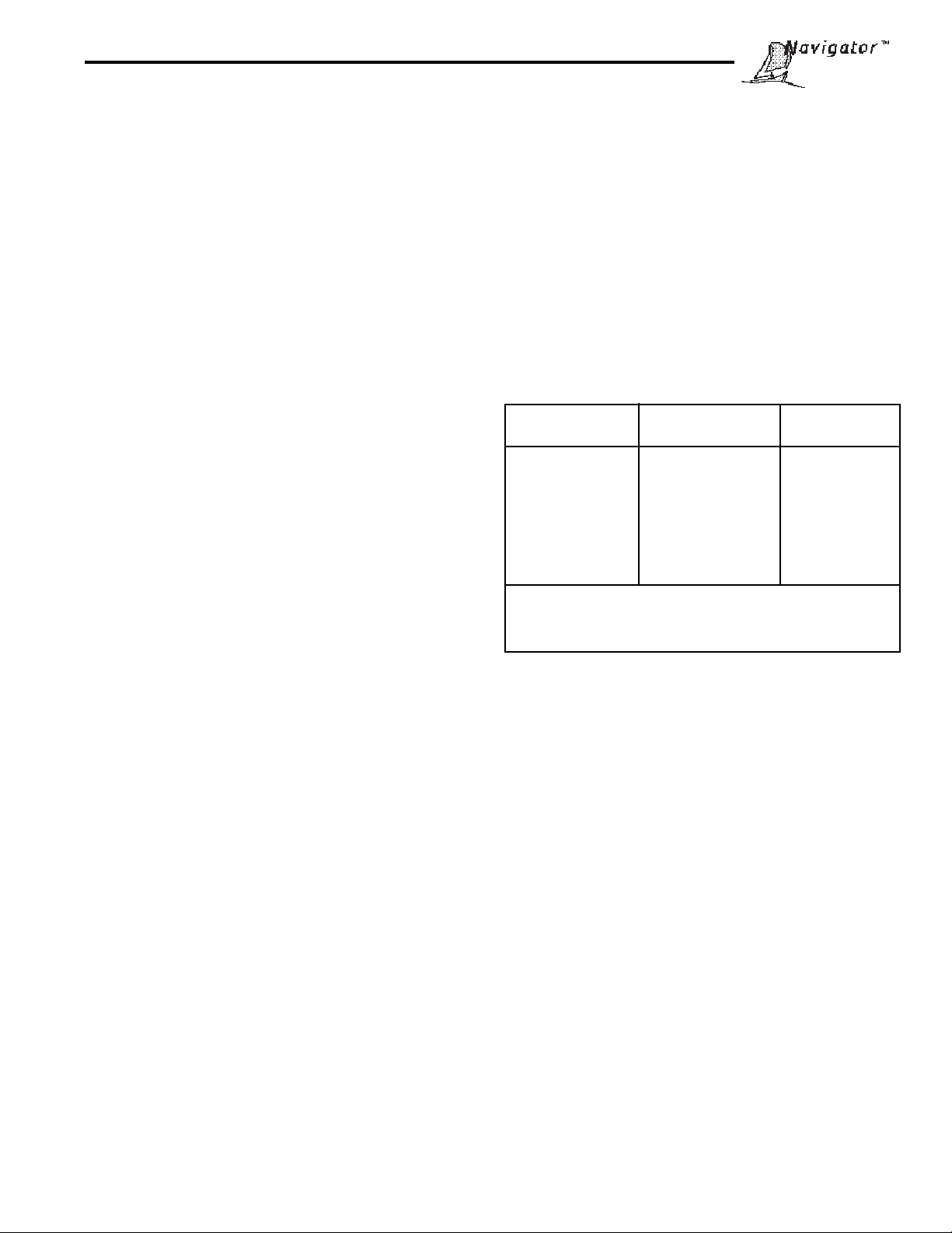
Procedure
• Press the Setup button, CAL is displayed.
• Press Enter button, CAL TYP is displayed.
• Press Enter button, CAL TYP InCAL is displa y ed.
• Press Enter button, INCAL is displayed.
IMPORTANT !
DO NOT DISTURB THE BALANCE DURING
CALIBRATION. IF THE MESSAGE UNSTBL
IS DISPLA YED , THE BALANCE W AS UNABLE
TO ACQ UIRE ST ABLE D ATA DURING INTERNAL CALIBRATION. THE BALANCE WILL
CONTINUE TO PERFORM INTERNAL CALIBRA TION UNTIL READINGS ST ABILIZE. THE
BALANCE WILL THEN COMPLETE THE INTERNAL CALIBRATION FUNCTION.
TO EXIT INTERNAL CALIBRATION MODE
BEFORE COMPLETION, PRESS ENTER OR
SETUP BUTTONS.
STABILITY CAN BE AFFECTED BY TEMPERATURE CHANGES, AIR CURRENTS, VIBRA TION, ETC...
NOTE: If a weight is left on the pan, the balance will
display CLR PAN (remove the weight from the pan).
The balance automatically resumes calibration.
The internal mass is positioned several times during
calibration and then removed, then after a few seconds,
CAL SET is displayed indicating a successful calibration. The displa y returns to WEIGH mode.
14
Page 15
3.3.2Calibration Message
On NavigatorTM balances equipped with the InCalTM feature, a screen prompt of CAL NOW appears when the balance
requires calibration. This display can be turned off if it is desired not to have the balance indicate that calibration is
required. Turning the display off has no effect on the basic balance operation.
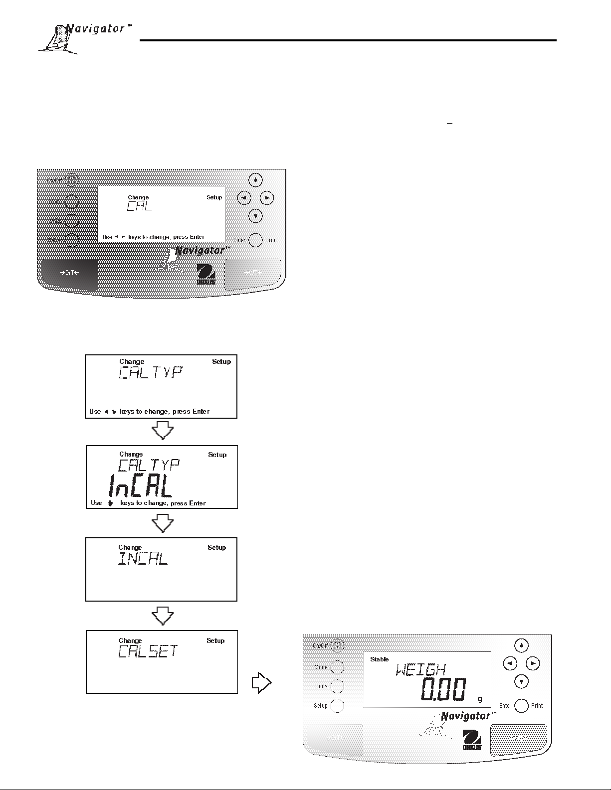
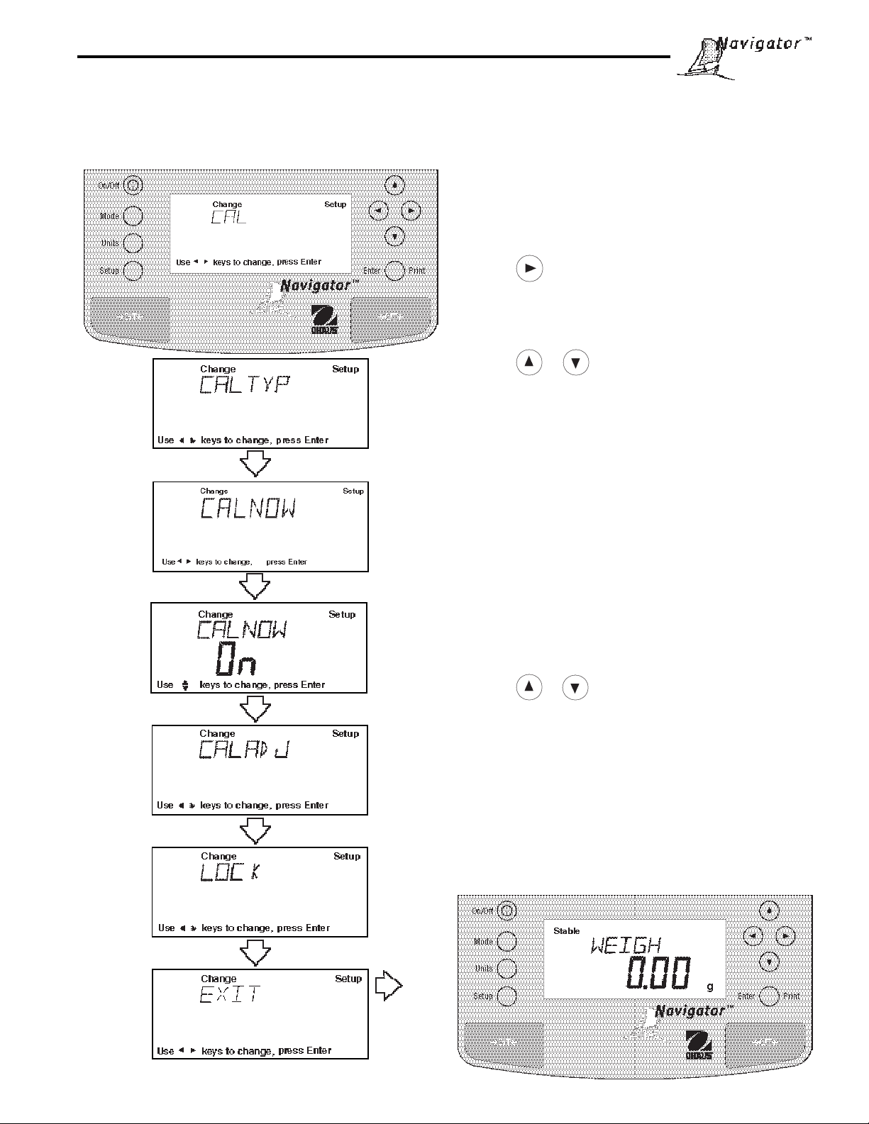
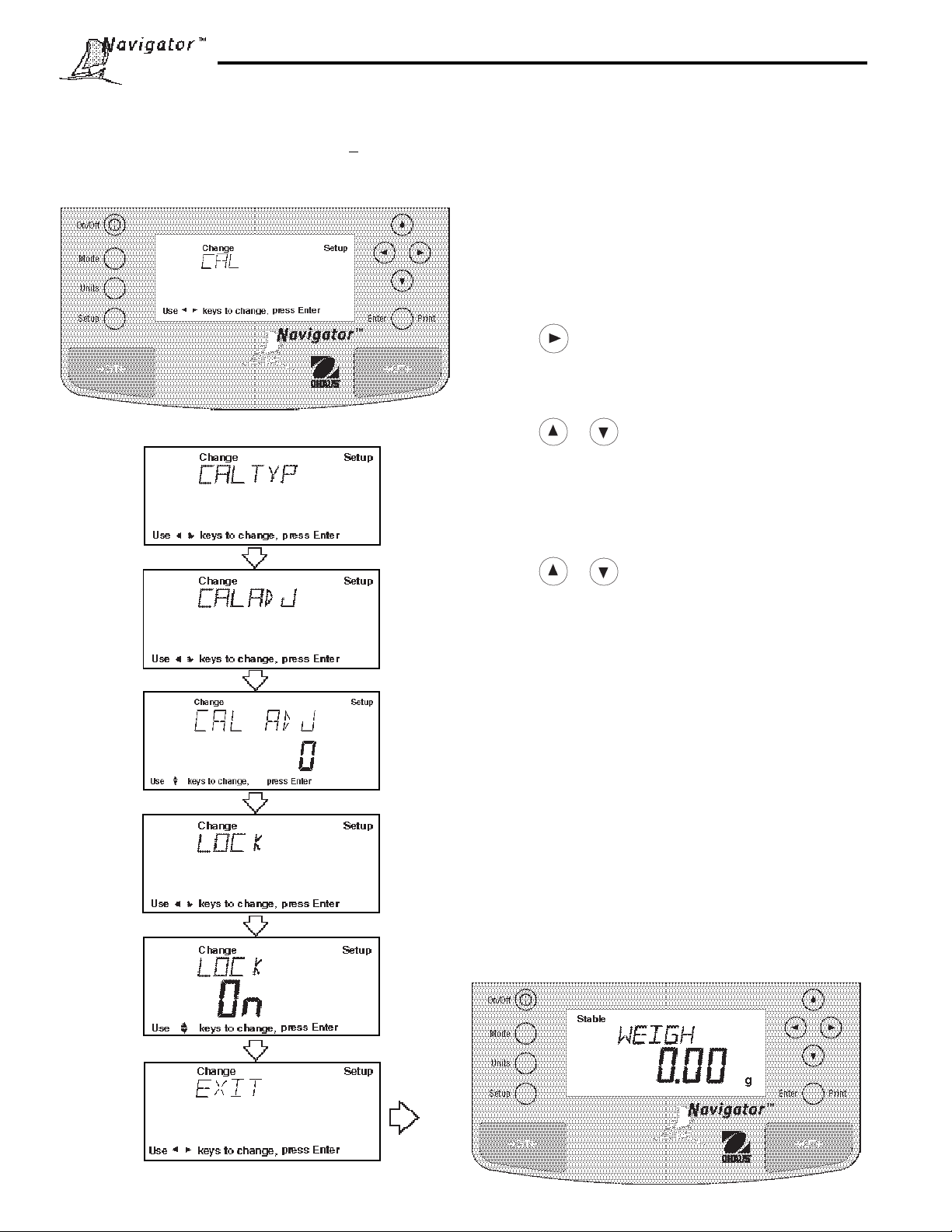
Procedure
• Press the Setup button, CAL is displayed.
• Press Enter button, CAL TYP is display ed.
• Press button, CAL NOW is displayed.
• Press Enter button, CAL NOW ON or OFF is displayed.
• Press or button and select either ON or
OFF. When OFF is selected, the CAL NOW message
will not appear in the display.
• Press Enter button, SAVED is momentarily display ed,
then the display indicates CAL ADJ.
NOTE: At this point you may continue with the calibra-
tion adjust procedure on the next page or exit.
The calibration adjust procedure is only used when it is
desired to calibrate the internal calibration mass to a
known external mass if a difference exits between the
known mass and the InCalTM value.
• Press Enter button, LOCK is displayed.
• Press or button and select either ON or OFF.
• Press Enter button, SA VED is momentarily display ed,
then the display indicates EXIT.
• Press Enter button, displa y returns to WEIGH mode.
15
Page 16
3.3.3Calibration Adjust
Balances with InCalTM contain software which allows the
internal calibration value to be adjusted by + 100 divisions
at full scale capacity using an external mass which is
traceable to a certified standard.
Procedure
• Perform the internal calibration procedure.
• Press >O/T< button to zero the balance.
• Place a mass equal to the
the balance on the pan. Note the reading on the balance and see if the balance indicates the exact
weight or indicates a higher or lower reading. If the
reading is higher or lower , proceed.
• Press the Setup button, CAL is displayed.
• Press Enter button, CAL TYP is display ed.
• Press button until , CAL ADJ is displayed.
• Press Enter button, CAL ADJ 0 should be displayed (0 is factory setting).
NOTE: Balance will retain last CAL ADJ setting.
• Press or button until desired number is
displayed.
• Press Enter button, SAVED is momentarily display ed,
then display indicates LOCK.
• Press Enter button, LOCK ON or LOCK OFF is
displayed.
• Press or button and select either LOCK ON
or LOCK OFF.
• Press Enter button, SA VED is momentarily displayed,
then EXIT is displayed.
• Press Enter button, displa y returns to WEIGH
mode. Note weight reading and remove mass from
pan.
• Perform the internal calibration procedure. The v alue
entered as an adjustment is now stored. Place the
calibration mass on the pan and check. Repeat procedure if further correction is required.
• T o return to factory setting, follow procedure above
and set CAL ADJ to 0.
span calibration value
of
16
Page 17
3.3.4Span Calibration
Span calibration utilizes two calibration points , one at zero and a choice of either half capacity or full capacity. All
balances will prompt for a particular weight which is shown in the table. If the prompt calls for a half capacity mass,
you can use a full capacity mass, the balance will accept it. If the prompt calls for a full capacity mass, you can use
a half capacity mass. This versatility allows calibration at other than full capacity. Sample display below illustrates a
210g balance.
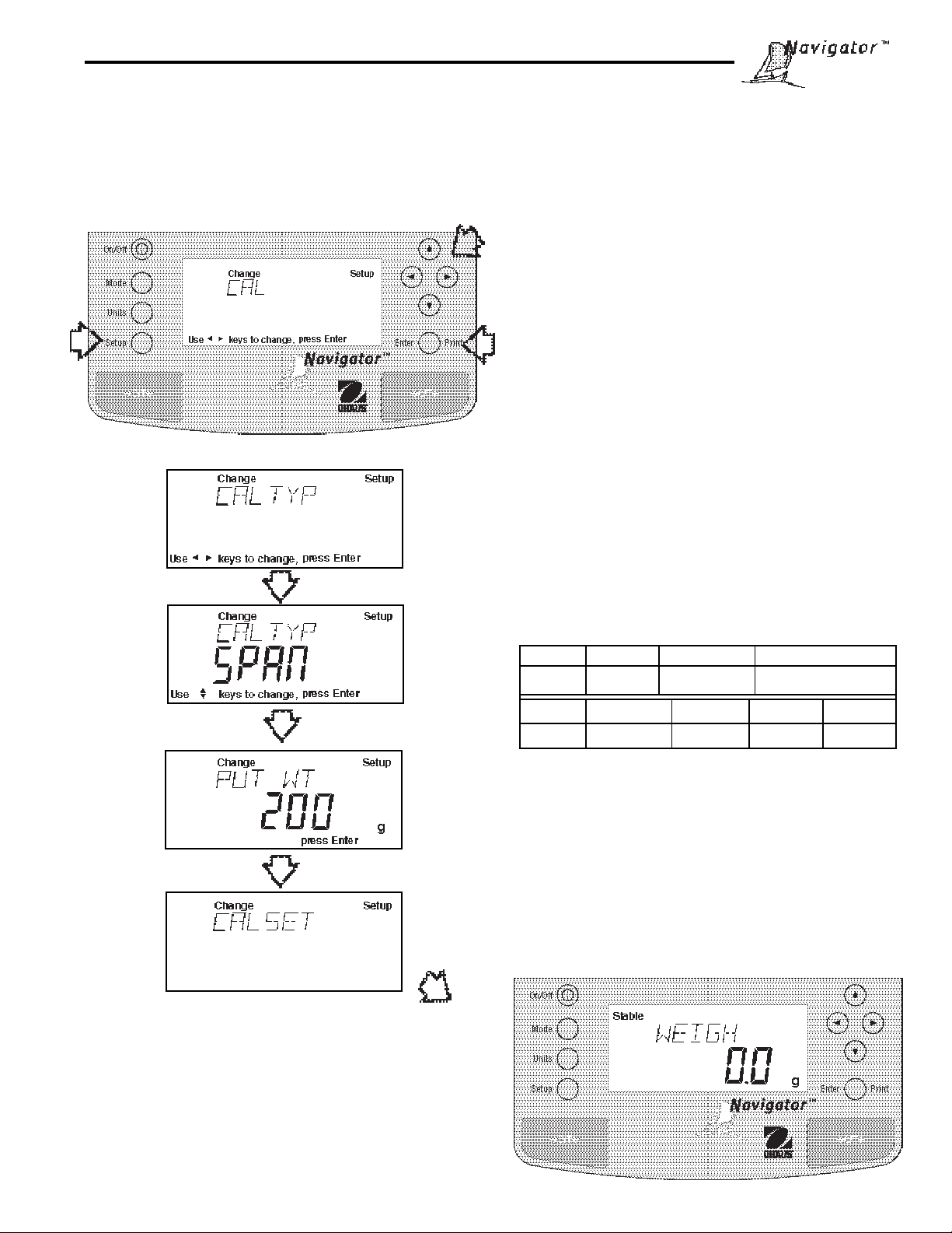
Procedure
• Clear the pan.
• Press the Setup button, CAL is displayed.
• Press Enter button, CAL TYP is displayed.
• Press Enter button to select SPAN calibration, CAL
TYP SPAN is displayed.
• Press Enter button, BUSY is displayed.
NOTE: If a weight is left on the pan, the balance will
display CLR PAN (remove the weight from the pan).
The balance automatically resumes calibration.
• Display changes to PUT WT 200g. The display ed
weight is the value of the mass to be used. See the
following table for masses that may be used with the
different model balances. V alues shown in bold are
displayed.
SPAN CALIBRATION MASSES
MODEL 32g 210g 410g
MASS 30g 100g, 200g 200g, 400g
MODEL 810g 2100g 4100g 8100g
MASS 400g, 800g 1kg, 2kg 2kg, 4kg 4kg, 8kg
• Place the calibration mass on pan.
NOTE: The PUT WEIGHT message indicates the
calibration mass that is on the pan.
• Press Enter button, BUSY is displayed. After a
few seconds CAL SET is displayed, the display then
returns to WEIGH mode.
• Span calibration is completed.
• Remove calibration mass from the pan.
17
Page 18
3.3.5User Calibration
User calibration is used when it is desired to calibrate the balance using a mass of known value. User calibration limits
are no less than the 1/2 nominal capacity point and no more than the display over limit. For example, on a 210g
balance, it's no less than 100.00g and no more than 210.09g. To use this calibration feature, proceed as follows:
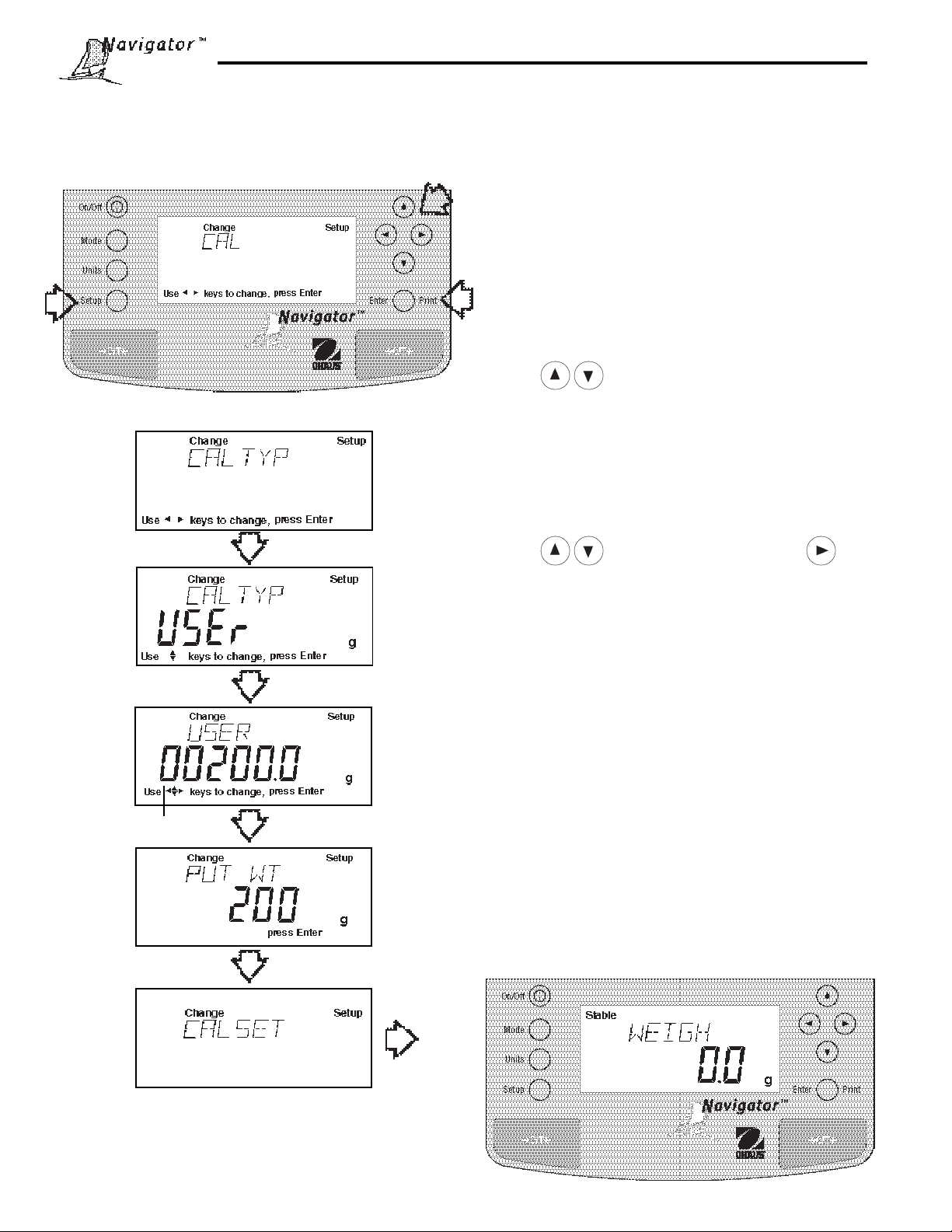
Procedure
• Clear the pan.
• Press the Setup button, CAL is displayed.
• Press Enter button, CAL TYP is displayed.
• Press Enter button.
• Press and scroll to select USER calibration,
CAL TYP USEr is displayed.
• Press Enter button, the display indicates the last
calibration mass value which was entered with the
first digit flashing. (Sampleillustrates 200g).
• Press to change value of digit and
button to advance to next digit. Enter the desired
mass value for y our balance . This number must be
at least 50% of the full span value.
(FLASHING)
• After entering value, press Enter button, BUSY is
displayed.
NOTE: If a weight is left on the pan, the balance will
display CLR PAN (remove the weight from the pan).
The balance automatically resumes calibration.
• Display changes to PUT WT 200 g.
• Place specified calibration mass on pan.
• Press Enter button, BUSY is displayed. After a
few seconds CAL SET is displayed, the display then
returns to WEIGH mode.
• User calibration is completed.
• Remove calibration mass from the pan.
18
Page 19
3.3.6Linearity Calibration
Linearity calibration utilizes three calibration points, one at zero, center span and full span. This method minimizes
deviation between actual and displayed weights within the balance's weighing range. Sample display illustrates a 210g
balance.
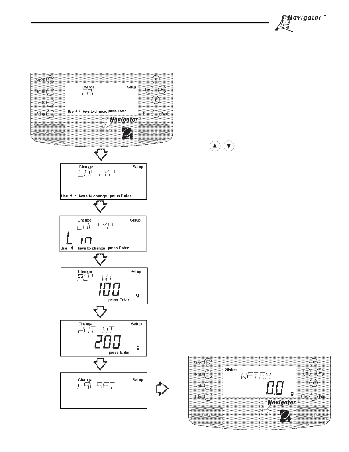
Procedure
• Clear the pan.
• Press the Setup button, CAL is displayed.
• Press Enter button, CAL TYP is displayed.
• Press Enter button.
• Press button and scroll to select Linearity
calibration, CAL TYP Lin is displa y ed.
• Press Enter button, BUSY is displayed.
NOTE: If a weight is left on the pan, the balance will
display CLR PAN (remove the weight from the pan).
The balance automatically resumes calibration.
• Display changes to PUT WT 100 g. The displayed
weight is half the capacity of the balance.
• Place specified calibration mass on pan.
• Press Enter button, BUSY is displayed. After a
few seconds displa y changes to PUT WT 200 g.
The displayed weight is the full capacity of the
balance.
• Place specified calibration mass on pan.
• Press Enter button, BUSY is displayed. After a
few seconds CAL SET is displa y ed, the displa y then
returns to WEIGH mode.
• Linearity calibration is completed.
• Remove calibration mass from the pan.
19
Page 20
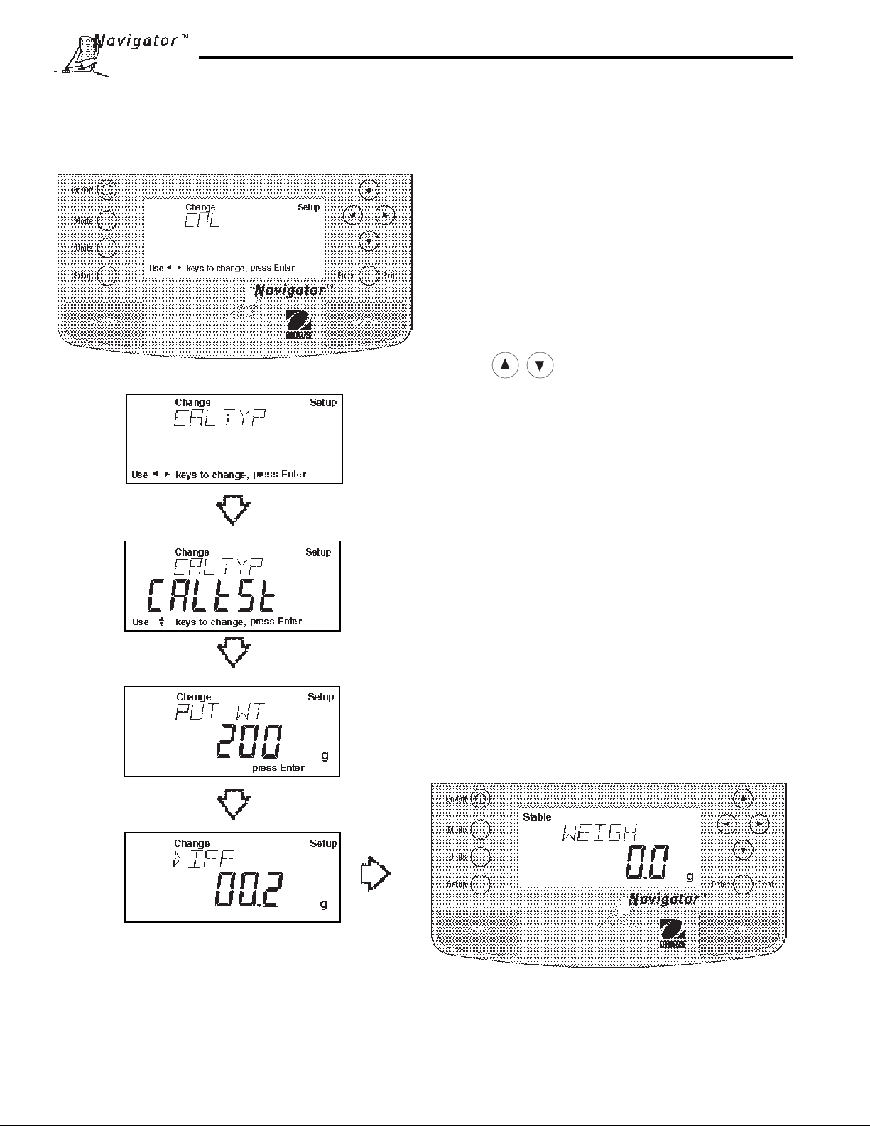
3.3.7Calibration Test
Calibration test feature allows a check of a known calibration mass against the last stored calibration information in the
balance. Sample display illustrates a 210g balance.
Procedure
• Clear the pan.
• Press the Setup button, CAL is displayed.
• Press Enter button, CAL TYP is displayed.
• Press Enter button.
• Press button and scroll to select CALtSt
calibration, CAL TYP CALtSt is displayed.
• Press Enter button, BUSY is displayed.
NOTE: If a weight is left on the pan, the balance will
display CLR PAN (remove the weight from the pan).
The balance automatically resumes calibration.
• Display changes to PUT WT 200 g. The displayed
weight is the full capacity of the balance.
• Place specified calibration mass on pan.
• Press Enter button, BUSY is displayed. After a
few seconds , DIFF is displa yed. The display now
indicates the actual diff erence in weight between
what value was just placed on the pan and the previous weight value which was stored in the balance.
After approximately 8 seconds, the displa y returns to
the WEIGH mode.
• Remove calibration test mass from the pan.
20
Page 21
3.3.8Calibration GLP Printout
If any option in the GLP Set Menu is turned On, GLP automatically prints data after calibration is completed.
Span Calibration Printout
When performing Span calibration with all GLP options
turned on, a printout is automatically made after the
calibration is completed.
Linearity Calibration Printout
When performing a Linearity calibration with all GLP
options turned on, a printout is automatically made after
the calibration is completed.
- - - - - SPAN CAL - - - - - -
12/01/98 1:00:00 PM
Bal Id 1234
Cal: 200.00g
Old: 200.00g
Dif: 0.00g
Wt.Ref......................................
USER NO 2056853
PROJ NO 100012
Name........................................
- - - - - END - - - - -
- - - - - LIN CAL - - - - - -
12/01/98 1:00:00 PM
Bal Id 1234
Cal: 200.00g
Old: 199.80g
Dif: 0.20g
Wt.Ref......................................
USER NO 2056853
PROJ NO 100012
Name........................................
Calibration T est Printout
When performing a Calibration Test with all GLP options
turned on, a printout is automatically made after the
calibration is completed.
User Calibration Printout
When performing a User Calibration with all GLP options
turned on, a printout is automatically made after the
calibration is completed.
- - - - - END - - - - -
- - - - - CAL TEST - - - - - -
12/01/98 1:00:00 PM
Bal Id 1234
Cal: 200.00g
Act: 200.20g
Dif: 0.20g
Wt.Ref......................................
USER NO 2056853
PROJ NO 100012
Name........................................
- - - - - END - - - - -
- - - - - USER CAL - - - - - -
12/01/98 1:00:00 PM
Bal Id 1234
Cal: 200.00g
Old: 200.20g
Dif: 0.20g
Wt.Ref......................................
USER NO 2056853
PROJ NO 100012
Name........................................
21
- - - - - END - - - - -
Page 22
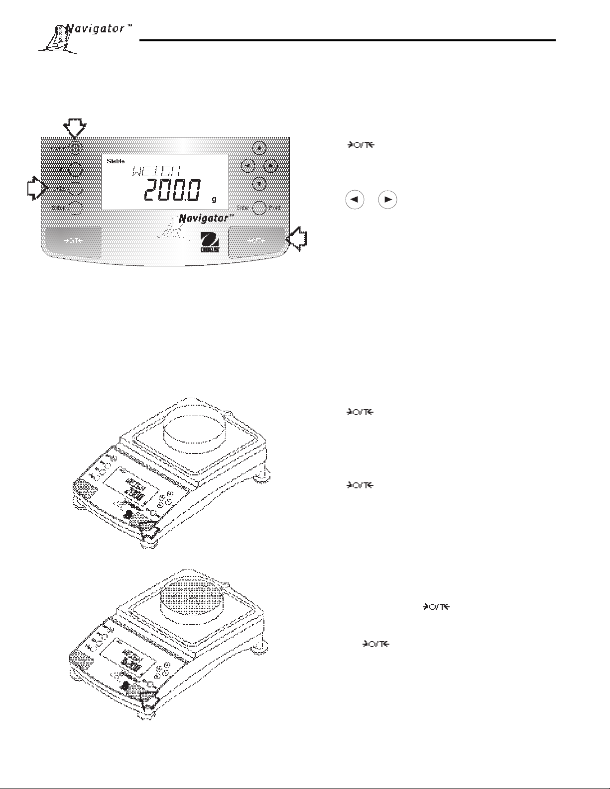
3.4 Weighing
NavigatorTM balances are shipped with grams only enabled. When the balance is to be used with other units of measure, the desired unit must be enabled. Refer to paragraph 4.8 to enable other measuring units. 32g models are
shipped ready to weigh in g, oz t, dwt and ct.
Procedure
• Press to rezero the display.
• Press Units button to select measuring unit.
• Press or button for desired measuring unit.
• Press Enter button, balance is now ready for weigh-
ing.
• Place the object(s) or material to be weighed on the
pan. Example illustrates a 200 gram weight on a high
capacity model.
• Wait for the stability indicator to appear before readin g the weight.
Zero/Tare
When weighing material or objects that must be held in a container, taring stores the container weight in the balance’ s
memory separate from the weight of the material in the container.
(
Example
Procedure
• Press with no load on the pan to set the
balance to zero.
• Place an empty container on the pan. Its weight is
displayed.
• Press . The display blanks until stable weight
readings are received, then indicates zero . The
container’s weight is stored in memory.
• Add material to the container. As material is added,
its net weight is displayed.
Container 200g)
• Removing the container and material from the platform will cause the balance to display the container’s
weight as a negative number . The tared weight will
remain in memory untili is pressed again or
the balance is turned off.
• Pressing resets the balance to zero.
(
Example
Material 1620g)
22
Page 23
3. 5Percent Weighing
Percent W eighing is
permits you to place a reference load on the balance, then view other loads as a percentage of the ref erence. The load
you place on the pan as a reference may be displayed as any percentage you select from 5% to 100% (in 1% increments). One hundred percent does not necessarily have to represent the reference load. Subsequent loads, displayed
as a percentage of the reference are limited only by the capacity of the balance . The default setting is Ref erence
100%. Refer to paragraph 4.7 to enable percent weighing.
enabled only
when Percent is turned ON in the Mode menu under Setup . Percent weighing
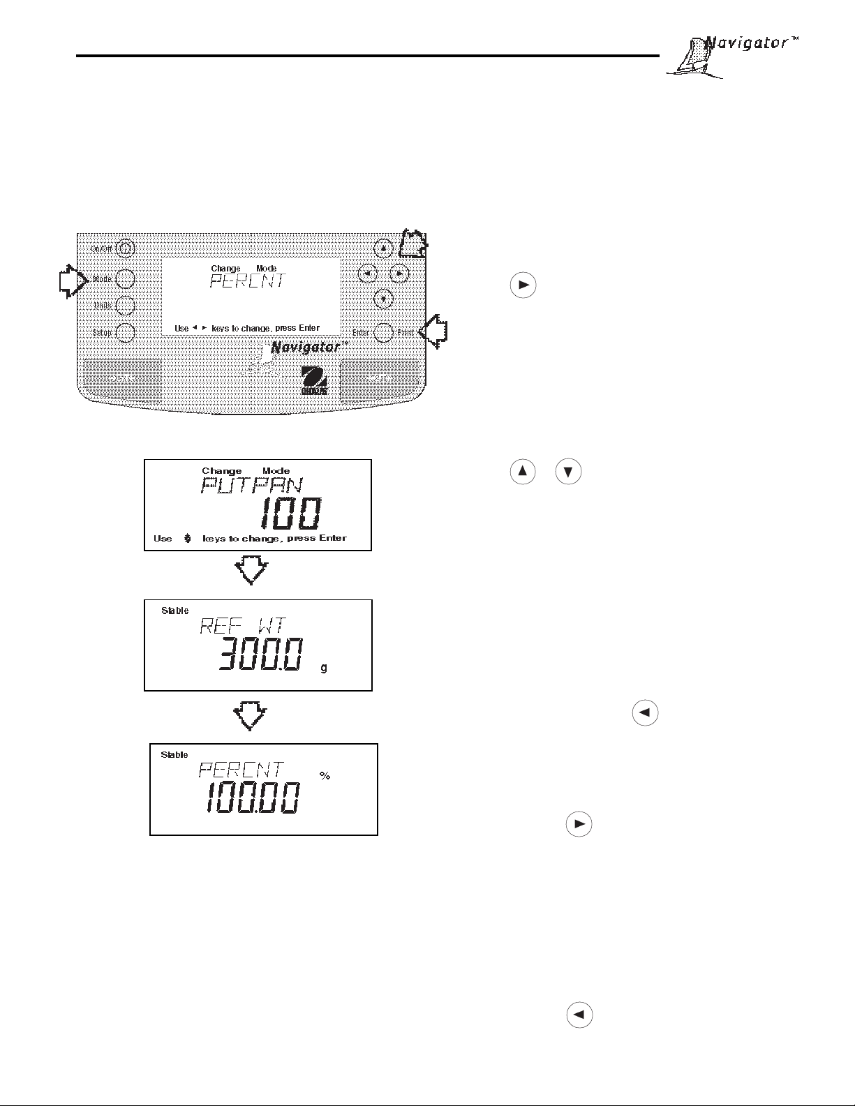
Procedure
• Press the Mode button, WEIGH is display ed.
• Press button until PERCNT is displayed.
• Press Enter button, PUTPAN 100% is displayed. If
a container is used, the balance can be tared at this
point. The % display momentarily blanks while the
balance is taring out.
• Put the reference load on the pan.
• Press or button and select reference
weight percentage (Percent Range 5 to 100). Hold
button down for fast change.
• Press Enter button to save setting, BUSY is displayed while the balance calculates the reference
weight. The balance shows the 100% equivalentreference weight for two seconds in the selected measuring unit, then displays the percentage which was
entered.
• T o view the weight of the ref erence load, press the
UNITS button, then press button until unit of
measurement such as GRAMS is displayed, then
press the Enter button.
• T o return to percent weighing, press the UNITS button
and then press button until PERCNT is dis-
played, then press the Enter button.
• Remove the reference weight from the pan and replace it with another load. The second load is displayed as a percentage of the ref erence . The displa y
illustrates 100% of the reference value.
• T o return to weighing mode, press the MODE button
and then press button until WEIGH is displa y ed,
then press the Enter button.
23
Page 24
3.6 Parts Counting
Parts Counting is
mode, the balance displays the quantity of parts you place on the pan. Since the balance determines the quantity
based on the average w eight of a single part, all parts must be reasonably uniform in weight. Ref er to paragraph
4.7 to enable parts counting.
enabled only
when Count is turned ON in the Mode menu under Setup. In the parts counting
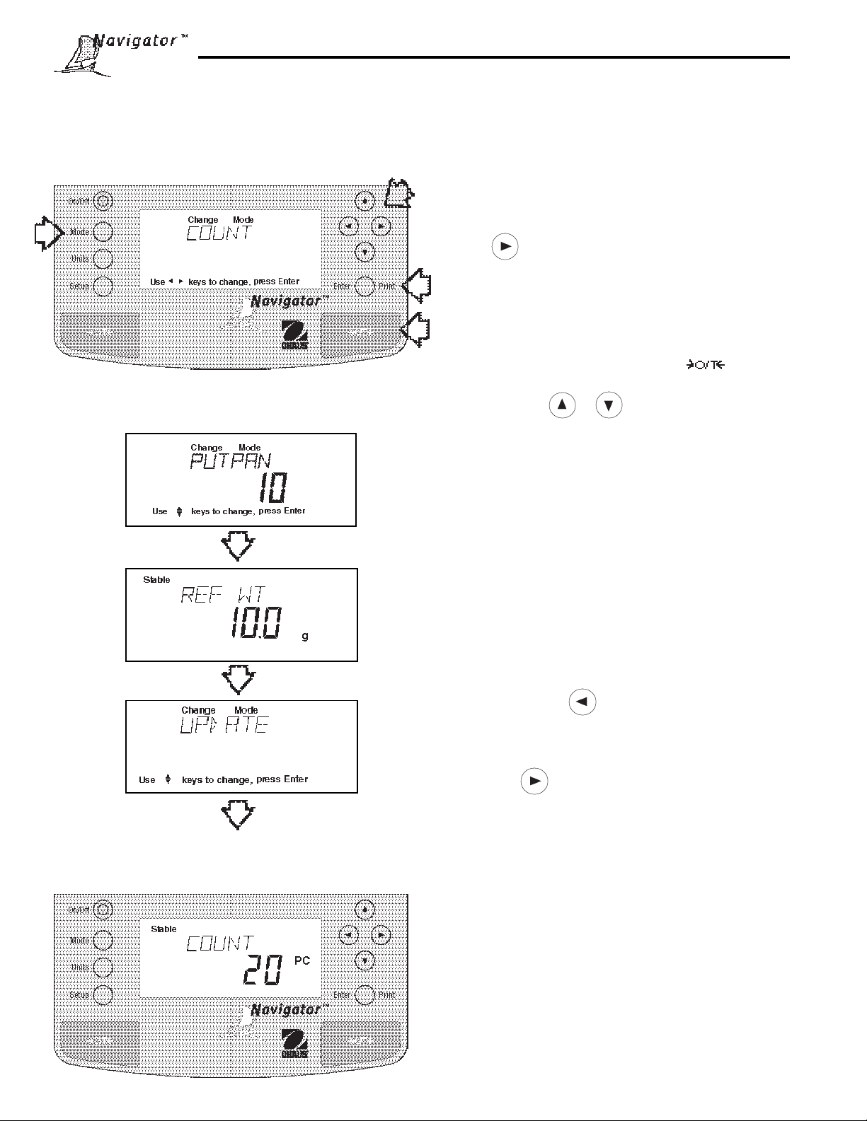
Procedure
• Press the Mode button.
• Press button until COUNT is displayed.
• Press Enter button. PUTPAN 10 is displayed
(default setting). Balance will retain last sample size
saved.
• Put a container on the pan and press to tare.
• Press and hold or button and select sample
size. Sample size may be 5 to 1000 parts.
• Place sample on the pan.
• Press Enter button to continue, display indicates
BUSY.
Balance displays the reference weight of an individual
part for five seconds and then displays the total number
of parts on the pan.
• Place parts to be counted on the pan. Balance displays number of parts.
• T o view the total w eight of the parts, press the UNITS
button, then press to select desired weighing
unit, then press the Enter button.
• T o return to parts counting, press the UNITS button,
then press button until COUNT is displayed,
then press the Enter button.
• T o begin counting with a new sample, repeat procedure.
Update
Update is a function which permits placing additional
samples which are greater than the value of the original
sample but less than three times the value. This action
increases the accuracy of the measurement.
• Place sample on the pan which is at least one but not
more than three times the original sample size.
• Press Mode button, COUNT is displayed.
• Press Enter button, UPDATE is displayed.
• Press Enter button, BUSY is displayed then the
reference weight followed by the new sample size.
24
Page 25
3. 7 Animal Weighing
Animal Weighing is
4.7 to enable animal weighing.
enabled only
when Animal is turned ON in the Mode menu under Setup. Ref er to parag raph
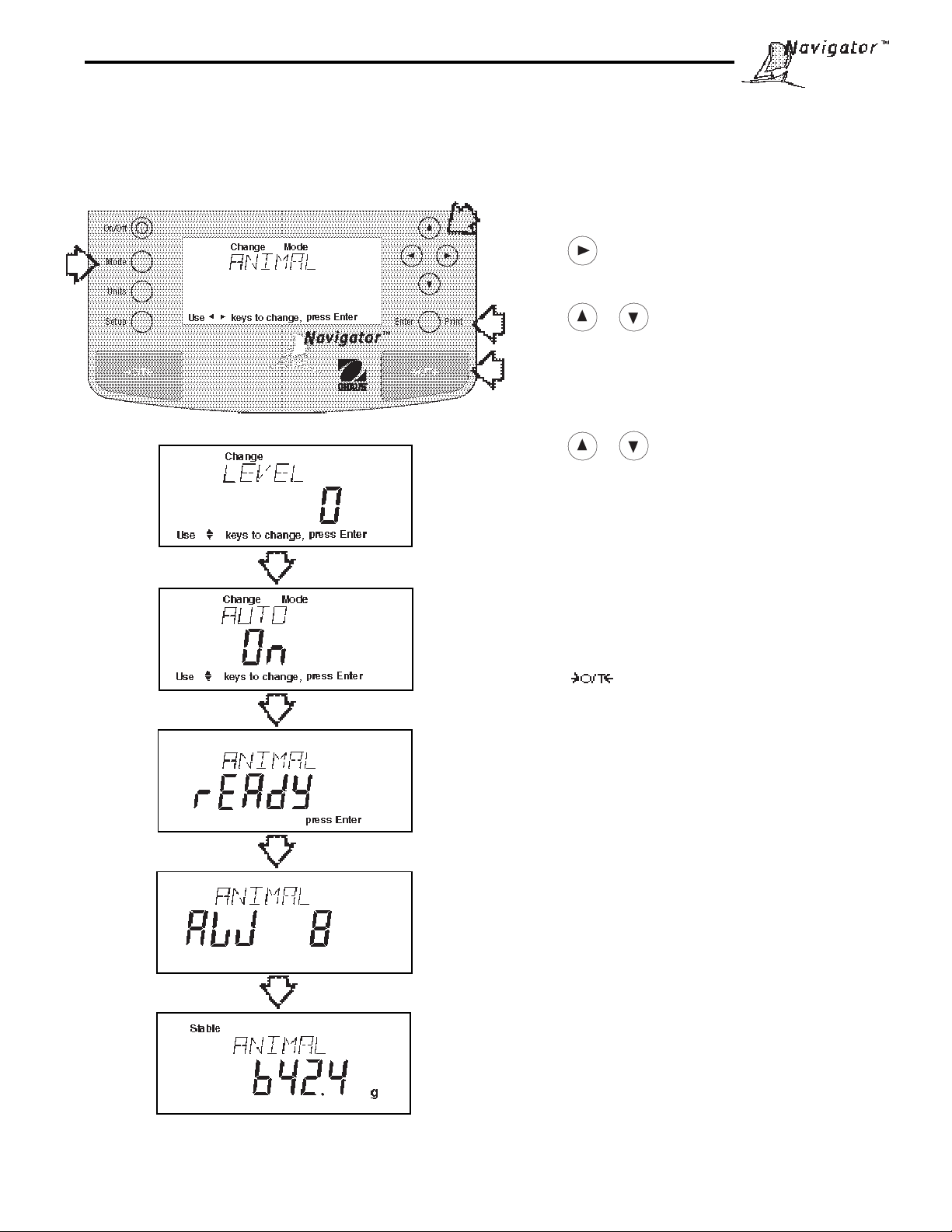
Procedure
• Press the Mode button.
• Press button until ANIMAL is displayed.
• Press Enter button to continue, LEVEL is displayed.
• Press or button to change sampling level,
0, 1, 2 or 3. 0 level is used for an inactive subject, 3
is used for a very active subject.
• Press Enter button to continue, A U TO is displayed.
• Press or button to select A U T O ON or OFF.
• Press Enter button to continue.
When the AUTO function is set ON, different subjects can
be weighed one after another without pressing any
buttons. When the balance displays READ Y, simply
place the subject on the pan.
Starting Animal Cycle
• Place animal container (if used) on pan.
• Press to tare the container.
• Place subject on pan.
• The animal cycle will automatically start if AUTO w as
set to ON.
• Press Enter button to start animal cycle if AUTO was
set to OFF.
During Animal Cycle
• Display shows countdown ending with A W 0, then
displays the subjects weight.
Completed Animal Cycle
• Balance displays weight until subject is removed from
the pan.
25
Page 26
3.8 Checkweighing
Checkweighing is
permits you to set a target nominal weight, and over and under weight limits . This type of weighing is used where
individual items must be checked against preset parameters. Refer to paragraph 4.7 to enable checkweighing.
enabled only
when Check is turned ON in the Mode menu under Setup. Checkweighing mode
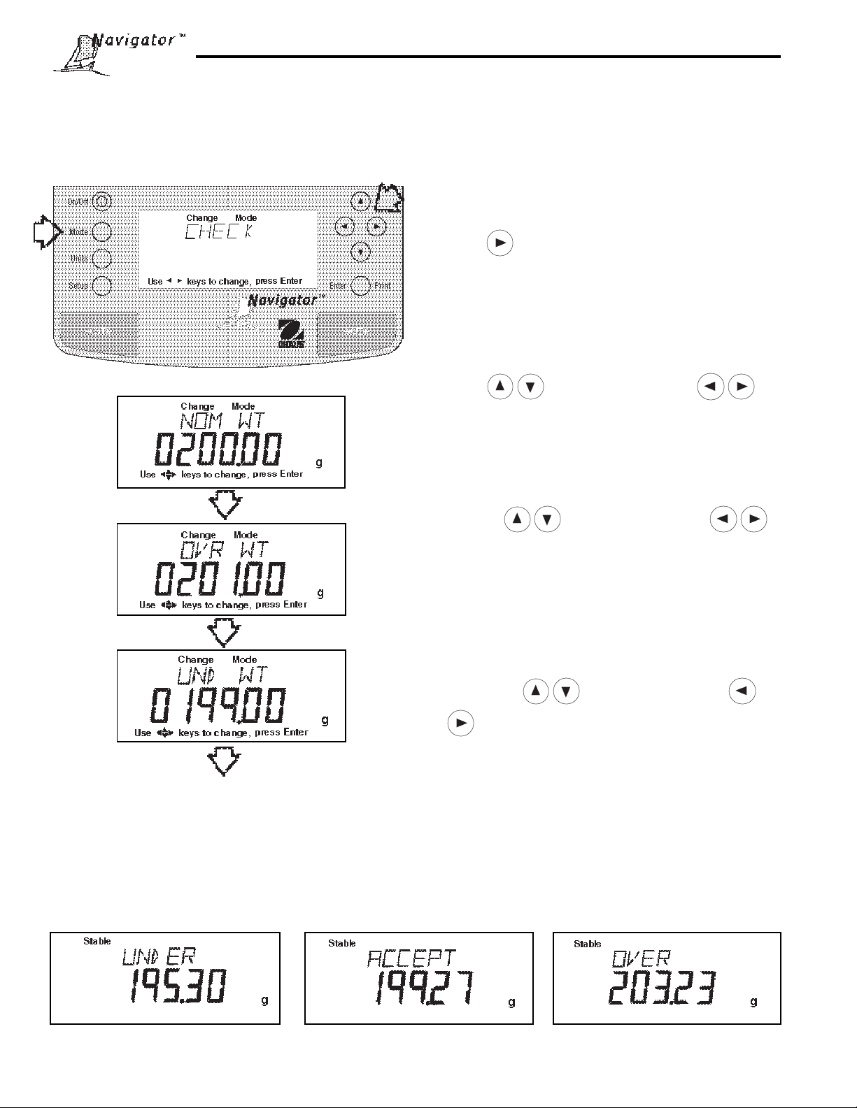
Procedure
• Press the Mode button.
• Press button until CHECK is displayed.
• Press Enter button to continue, NOM WT is displayed. The n umerical display indicates 0000.00 with
the first digit flashing. The sample display indicates
0200.00g
• Press to change the digit and to
go to the next digit. Enter the desired nominal value.
• Press Enter button to continue. OVR WT is displayed. The n umerical display indicates 0000.00 with
the first digit flashing. Enter the over weight value by
NOTE: Samples shown below are for a 200g nominal
setting. The tolerances were set for 1g over and under.
pressing to change the digit and
to go the next digit. The sample display indicates
0201.00g.
• Press Enter button to continue. UND WT is dis-
played. The n umerical display indicates 0000.00 with
the first digit flashing. Enter the under weight value
by pressing to change the digit and
to go the next digit. The sample display indi-
cates 0199.00g.
• Press Enter button to continue.
• Place item to be checked on the balance pan.
ACCEPT is displayed when the item is within limits.
OVER and/or UNDER is displa y ed if the item is out of
the tolerance set in the limits.
UNDER is displayed for weights less
than or equal to the UND WT limit
T ypical Nominal Weight Displa y
26
OVER is display ed f or weights greater
than or equal to the OVR WT limit
Page 27
3.9 Printing Data
Printing data to an external computer or printer requires that the communications parameters in the Setup menu, print
options and communication parameters be set first. Refer to page 23 Print menu settings and page 25 for RS232
communication settings.
Procedure
• Press the Print button. Printing to an external printer
or computer will occur each time the Print button is
pressed unless the autoprint feature is turned on in
which case, printing can occur in a continuous fashion, at specified intervals or each time a stable reading is achieved.
Sample printout is shown below with time turned on.
SAMPLE PRINTOUT
12/01/98 12:01:37 AM
429.5 g
For a review of of printing samples, refer to Section 4
Setting Up Your Balance. What is printed is controlled
by the GLP Set Menu and the selection of GLP
Continous or GLP Tare in the Print Menu.
27
Page 28
4. SETTING UP YOUR BALANCE
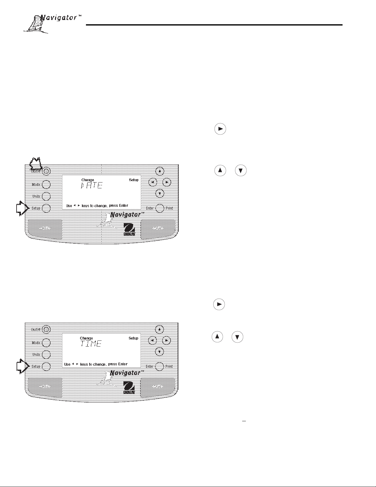
4. 1 Setting Date and Time
Your NavigatorTM balance provides date and time data which can be viewed on a computer or printed out on an external
printer. When you put y our new instrument into operation f or the first time, y ou should enter the current date and the
time. These settings are retained as long as the balance remains connected to an A C power source using the A C
Adapter. Date and time are not retained with battery operation.
Date
Date is a feature which enables the balance to be set to a
U.S . date standard or European date standard. U .S.
standard has the month, day, followed by the y ear, each
separated by (/) in the printout. The European date
standard has the day first, followed by the month and
then the year; each separated b y a period. The def ault
setting is Mdy.
Time
Time is a feature which enables the balance to be set to
the current time in either 12 hour or 24 hour periods. The
default setting is 12 hour .
Procedure
• Press the Setup button, CAL is displayed.
• Press button and select Date from the menu.
• Press Enter button, TYPE is display ed.
• Press Enter button, SET M d y, d M y, y M d, M y d,
y d M, or d y M is displayed.
• Press or button and select type of date.
• Press Enter button, SAVED is displayed, then SET is
displayed.
• Press Enter button, date is displayed.
• Using arrow buttons, enter the correct date.
• When the correct date is entered, press Enter button,
SA VED displa ys momentarily and EXIT appears.
• Press Enter button, balance returns to a weighing
mode.
Procedure
• Press the Setup button, CAL is displayed.
• Press button and select Time from the menu.
• Press Enter button, TYPE is displayed.
• Press Enter button, TYPE 12 hr is display ed.
• Press or button and select 12 hr or 24 hr.
• Press Enter button, SAVED is displa yed momentarily
then SET is displayed.
• Press Enter button,SET with time is displayed.
• Using arrow buttons, enter the correct time.
• When the correct time is entered, press Enter button,
SA VED displays momentarily and ADJUST appears.
• Press Enter button, 0 appears.
Adjustments up to +60 seconds per day can be made
to the balance internal clock. Using arrow buttons,
enter time correction and press Enter button. SA VED
displays momentarily and EXIT appears. Press Enter
button, balance returns to a weighing mode.
28
Page 29
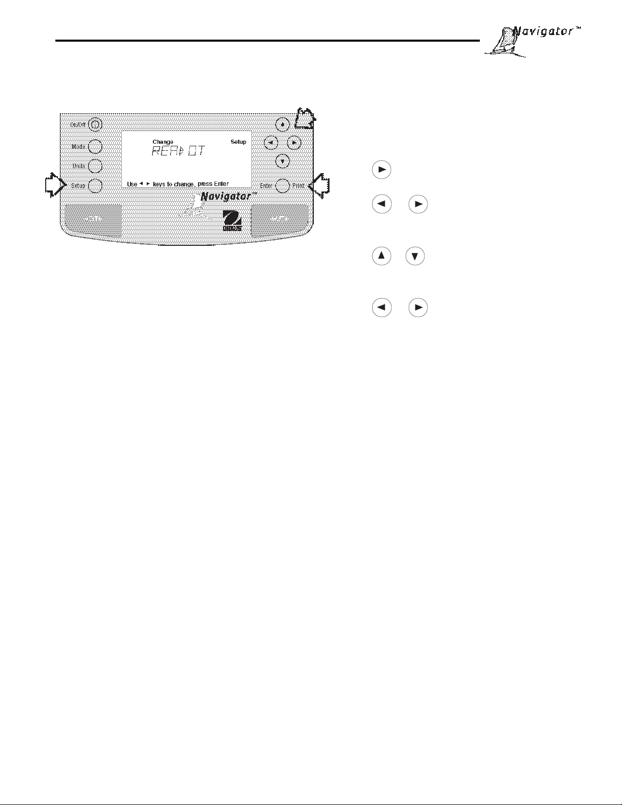
4.2Readout
The Readout menu is used to adapt the balance to environmental conditions. It contains four menus: Stable, Auto 0,
Filter, Lock and Exit. Loc k, when set ON, locks the Readout settings entered, pro viding the Lock s witch underneath
the balance is also set ON.
Stability
The stability range can be set to a preset tolerance limit. When the balance reading is stable within preset limits, the
stability indicator remains ON. When a displa y ed weight changes bey ond the allowab le range, the stability indicator
turns OFF, indicating an unstable condition. Factory default setting is shown in bold type .
Procedure
To select any of the items in the Readout menu, proceed
as follows:
• Press the Setup button, CAL is displayed.
• Press button until READO T is display ed.
• Press Enter button to continue, STABLE is displayed.
• Press or button until either STABLE, AUT O
0, FILTER, LOCK or EXIT is displayed.
• Press Enter button to continue.
• Press or button and select the desired menu
setting. Review settings available below.
• Press Enter button, SAVED is displa y ed.
• Press or button to continue to LOCK and
EXIT.
• Press Enter button to continue.
.5 d Smallest range: stability indicator is ON only
when displayed weight is stable within .5 divisions.
1 d Reduced range.
2 d Normal range.
5 d Largest range, stability indicator is ON when displayed weight
changes up to 5 divisions.
When the RS232 interface is configured to print stable data only, the stability range also governs data output. Displayed data will only be output if it is within the selected stability range.
Auto-Zer o
Auto-Zero minimizes the eff ects of temperature changes and shift on the z ero reading. The balance maintains the zero
display until the threshold is exceeded. Factory default setting is shown in bold type.
OFF T urns Auto-Zero OFF.
.5 d Sets threshold to .5 divisions.
1 d Sets threshold to 1 division.
3 d Sets threshold to 3 divisions.
Filter
Filter compensates for vibration or excessive air currents. Default settings are shown bold.
-0- minimum filtering, fastest stabilization time
-1- reduced filtering, fast stabilization time
-2- normal filtering, normal stabilization time.
-3- maximum filtering, slowest stabilization time.
Lock
Lock ON/OFF can only be changed when the hardware Lock Switch is set OFF/disabled. A menu is locked when the
menu lock is set ON and the Lock switch is ON. Lock, when selected and turned on, locks all of the entries made
under the Readout menu. In the loc ked condition, items ma y be looked at b ut not changed in the men u. When set
OFF, entries may be changed. OFF is the default setting. Ref er to paragraph 4.12 f or Menu Loc k-Out Protection.
29
Page 30
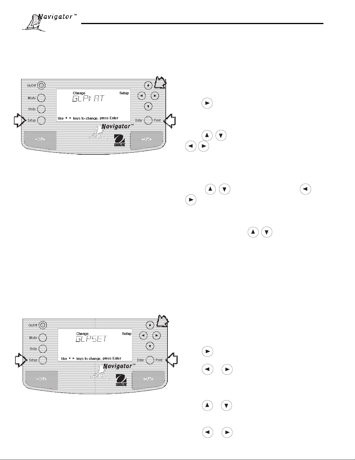
4.3 Good Laboratory Practices (GLP) Data
The GLP Data menu enables the storage of a user identification number (6 digits) and/or a project number (6 digits).
When entered into the balance, the identification number and project number are available when printing, provided they
are turned on in the GLP Set menu. A lock setting is also available which locks in the user identification and project
number.
Procedure
To enter data in the GLP Data menu, proceed as follows:
• Press the Setup button, CAL is displayed.
• Press button until GLPDAT is displayed.
• Press Enter button to continue, USER NO is displaye d.
• Press Enter button to continue.
• Press buttons to change digit values and
buttons to advance to next digit and enter a
6 digit number for the user number .
• Press Enter button to save setting, PROJNO is displayed.
• Press Enter button to continue.
• Press to change digit values and
to advance to next digit as directed by thedisplay
and enter a 6 digit number for the project number .
• Press Enter button to save setting, LOCK is displayed.
• Press Enter button, press to select ON or OFF.
• Press Enter button to save setting, SAVED is dis-
played then EXIT.
• Press Enter button, balance returns to weigh mode.
4.4Good Laboratory Practices (GLP) Set
Good Laboratory Practices (GLP) Set menu allows the selection of and will permit printing of Time, Balance Identification, User Number, Project Number , Diff erence and Name data. The default setting is OFF. When an e xternal printer is
used with the balance calibrated, and all items are set ON, the printer will print out calibration data for audit trail
purposes and will indicate date, and time. (It should be noted that the User number and Project number must be
entered in the GLP Data menu before printed data is available).
Procedure
To select any of the items in the GLP Set menu, proceed
as follows:
• Press the Setup button, CAL is displayed.
• Press button until GLPSET is displayed.
• Press Enter button to continue.
• Press or button until either TIME, BAL ID
(see note), USER NO, PROJ NO, DIFF , NAME,
LOCK or EXIT is displayed.
• Press Enter button to continue.
NOTE: Balance ID (BAL ID) represents the actual serial
number of the balance and cannot be entered or changed.
Setting BAL ID ON allows printouts to display the serial
number of the balance during GLP data.
• Press or button and select either ON or
OFF for each entry .
• Press Enter button to save setting.
• Press or button to continue or EXIT.
• Press Enter button, balance returns to weigh mode.
30
Page 31

4.5 Print
The Print menu provides a number of options which can be turned ON or OFF. It contains eight menus: Auto Print,
feature which includes selection of Off, Continuous , Interval and On Stability, Interval, specifies time interval for
automatic output of displayed data, Stable data-only feature, Numerical only or full display data for output, GLP
Continous, GLP Tare, Reference when selected prints reference weight v alue and Lock when set on enab les you to
lock the settings. Refer to decriptions below and review settings before proceeding.
Procedure
• Press the Setup button, CAL is displayed.
• Press button until PRINT is displayed.
• Press Enter button to continue.
• Press or button until either AUTOPR,
INTER, ST ABLE, NUMERI, GLPCON, GLPTAR,
REF, LOCK or EXIT is displayed.
• Press Enter button to continue.
• Press or button and select either menu
settings of ON or OFF or settings shown below .
• Press Enter button to save setting.
• Press or button to select next item or EXIT.
• Press Enter button to continue.
Auto Print
When enabled, the Auto Print allows the balance to automatically output display data in one of three ways: continuously, at user specified time intervals, or upon stability. Default setting is shown in bold.
OFF turns off auto print
Cont outputs data continuously
Inter provides a user specified output interval
On Stb provides data output everytime a stable reading is achieved
Interval
Can be set to provide a specified output interval between 1 and 3600 seconds.
Print Stable Data Only
When set On, permits only stable display data to be output. OFF is the default setting.
Print Numeric Data Only
When Numeric Data Only function is turned ON, allows the balance to output numeric data only for RS232 output.
OFF is the default setting.
31
Page 32

4.5 Print (Cont.)
GLP Continuously
When the GLP Continuously function is set ON, it allows the balance to output the GLP selections each time a weight
value is output. OFF is the def ault setting. The follo wing e xample is with GLP Continuously On.
Sample Printout
GLP Set Menu
Options Turned On
12/01/98 12:01:37 AM
129.50 g
12/01/98 12:01:52 AM
Bal Id
129.80 g
12/01/98 12:02:17 AM
Bal Id
USER NO 1000001
129.80 g
12/01/98 12:02:43 AM
Bal Id
USER NO 1000001
PROJ NO 2000002
129.50 g
12/01/98 12:02:43 AM
Bal Id
USER NO 1000001
PROJ NO 2000002
Name . . . . . . . . .. . . . . .
129.50 g
Time = On
Time = On
Balance ID = On
Time = On
Bal ID = On
User No. = On
Time = On
Bal ID = On
User No = On
Proj No = On
Time = On
Bal ID = On
User No = On
Proj No =
Name = On
GLP Once After Tare
When the GLP Tare function is set ON, it allows the balance to output the GLP selections and weight measurement
once after tare. OFF is the default setting. The following example is with GLP Once After Tare.
GLP Set Menu
Options Turned On
12/01/98 12:01:37 AM
129.50 g
129.60 g
129.70 g
129.70 g
129.70 g
Time = On
Reference
When the Reference function is set ON, it prints the value of weight used as a ref erence in either P ercent or P arts
Counting modes. OFF is the default setting.
Lock
Lock ON/OFF can only be changed when the hardware Lock Switch is set OFF/unlocked. A menu is locked when the
menu lock is set ON and the Lock Switch is ON. Lock, when selected and turned on, locks all of the entries made
under the Print menu. In the loc ked condition, items may be looked at but not changed in the menu. When set OFF,
entries may be changed. OFF is the default setting. Refer to paragraph 4.12 for Menu Lock-Out Protection.
32
Page 33

4.6 RS232
The RS232 menu provides communication parameters which can be set to accommodate external printers or computers. It contains six men us: Power , Baud rate, Parity, Data, Stop bits and Loc k ON or OFF. Lock, when set ON, locks
the communication settings entered, providing the Lock Switch underneath the balance is also set ON.
Procedure
• Press the Setup button, CAL is displayed.
• Press button until RS232 is displayed.
• Press Enter button, POWER is displayed.
• Press Enter button.
• Using or button, select ON or OFF. If you
are using the balance on battery power, and w ant
communications to an external device, you must select ON. These settings do not matter when using the
balance on AC Adapter power as the communications
interface is always ON.
• Press Enter button,BAUD is display ed.
• Press Enter button.
• Using or button and select the desired
menu setting, then press Enter button. The displa y
advances to PARITY.
• Repeat the above three steps and enter desired
settings for PARITY , D AT A, STOP and LOCK. LOCK
has a choice of ON or OFF. When set ON, the
communication parameters are locked and cannot be
changed. The displa y indicates LOCKED when
viewing the parameters.
• When EXIT appears on display , press Enter b utton to
save settings. Balance returns to weigh mode.
Po wer
This menu is used when balance is battery operated. The default setting is Off. To use the RS232 with battery
operation, P ower must be set ON. The RS232 is alwa ys operational when the balance is operated with an A C Adapter .
Baud Rate
This menu is used to select the desired baud rate. There are five available baud r ates to choose from: 300, 1200,
2400, 4800 and 9600, the default setting is 2400.
Parity
This menu is used to select parity settings. Parity can be set to either Odd, Even or None, the default setting is
None.
Data Bits
This menu is used to select data bits. Data bits can be set to 7 or 8, the default setting is 7.
Stop Bits
This menu is used to select the number of stop bits. Stop bits can be set to 1 or 2, the default setting is 2.
Lock
Lock ON/OFF settings can only be changed when the hardware Lock Switch is set OFF/disabled. A menu is locked
when the menu lock is set ON and the Lock Switch is ON. Lock when selected and turned on, locks all of the entries
made under the RS232 menu. In the loc k ed condition, items ma y be looked at b ut not changed in the menu. When
set OFF, entries may be changed. OFF is the def ault setting. Refer to paragraph 4.12 for Menu Lock-Out Protection.
33
Page 34

4.7 Mode
The Mode menu permits the selection of five modes which can be turned ON or OFF. These modes are: Weigh,
Percent, Count, Animal W eighing, Checkweighing. Weigh is turned ON and all others hav e a default setting of OFF.
When any of the modes are turned ON, they can be selected for operation from the Mode button.
Procedure
• Press the Setup button, CAL is displayed.
• Press button until MODE is displayed.
• Press Enter button, WEIGH is displayed.
• Press Enter button.
• Press or button and select either ON or
OFF.
• Press Enter button to continue. Display advances to
PERCNT .
• Repeat above steps for PERCNT , COUNT , ANIMAL,
CHECK and LOCK.
• When EXIT appears on the display , press Enter
button to save setting. Balance returns to weighing
mode.
Weigh
The W eigh men u is alw ays set to ON as a default.
Percent
Percent weighing permits you to place a ref erence load on the balance, then vie w other loads as a percentage of the
reference. Selection is made using the Mode button. The default setting is OFF.
Count
Count is used for counting quantities of parts. Selection is made using the Mode button. The default setting is OFF.
Animal weighing
Animal weighing provides special settings to compensate for animal movements. Selection is made using the Mode
button. The default setting is OFF.
Checkweighing
Checkweighing permits setting nominal weight, over weight and under weight values into the balance where individual
items must be checked against preset parameters . The default setting is OFF.
Lock
Lock ON/OFF can only be changed when the hardware Lock Switch is set OFF/disabled. A menu is locked when the
menu lock is set ON and the Lock Switch is ON. Lock when selected and turned on, locks all of the entries made
under the Mode menu. In the locked condition, items may be looked at but not changed in the menu. When set OFF,
entries may be changed. The def ault setting is OFF. Ref er to paragraph 4.12 f or Menu Lock-Out Protection.
34
Page 35

4.8 Units
The Units menu permits the selection of the measuring units which can be turned ON or OFF and locked.
Procedure
• Press the Setup button, CAL is displayed.
• Press button until UNITS is displayed.
• Press Enter button to continue.
• Press or button until desired measuring unit
is displayed.
• Press Enter button to continue.
• Press or button and select either ON or OFF.
• Press Enter button to save setting.
• Press or button to select next item.
• Repeat above steps to turn selected measuring units
ON or OFF, then, continue to LOCK and EXIT .
• Press Enter button to save settings.
Units
Measuring units settings are made using the Units menu. This menu permits the measuring units to be turned ON or
OFF. The default setting is OFF.
Lock
Lock, when selected and turned ON, locks all of the entries made under the Units menu. The default setting is OFF.
Refer to paragraph 4.12 for Menu Lock-Out Protection.
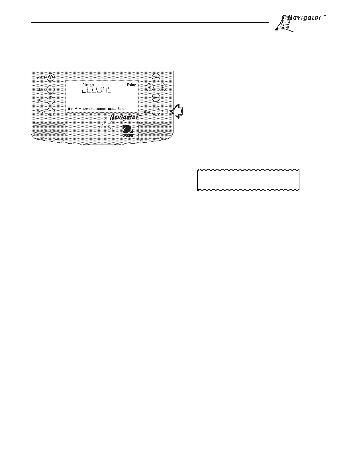
4.9 Global
This menu contains two functions which can be activated by selecting YES. These functions are: List, and Reset. The
default settings are NO. Global List is a convienent method of e xamining which parameters are set up in the balance.
The parameters do not show up on the display but print out when selected. When Version is selected, the software
revision of the balance is displayed. Global Reset when set ON will reset
the Lock Switch is set OFF. This is a convienent method of restoring factory settings. To protect menu settings, each
individual menu must have Lock ON, the Global menu Lock must be ON and the Lock Out switch must be set ON.
all menus
to factory default settings only if
Procedure
• Press the Setup button.
• Press button until GLOBAL is displayed.
• Press Enter button to continue, LIST is displayed.
• Press or button until either LIST, RESET,
VER, LOCK or EXIT is displayed.
• Press Enter button to continue.
• Press or button and select either YES or
NO for LIST and RESET. When either LOCK or EXIT
is selected, ON or OFF settings are available..
• Press Enter button to save setting.
• Press or button to select next item orEXIT.
• Press Enter button to save.
35
Page 36

4.9 Global (Cont.)
List
This menu can be used to output a listing of current menu settings via the RS232 interface. When YES is selected, all
menu settings will be output either to an external printer or computer. To use this feature, your balance must be connected to a computer or printer. The def ault setting is NO.
The partial sample shown, indicates the status in the
SAMPLE PRINTOUTS
menus.
NAVIGATOR xxxxxx-xxx
Sr #x.xx OS#x.xx G#x.xx
Time= 12hr 3:19:51 PM
Date= m/d/y 12/01/98
Function = Weigh
ReadOut Menu
Stb= 2 d
AZT= .5 d
Filter= 1
GLP Menu
Time/Date= On
Bal Id= On
User No.= On
Proj No.= On
DIFF= On
Name= On
Print Menu
Auto Print= Off
Interval= 7
Stable Print= On
NU= On
GLP Cont = Off
GLP on Tare = Off
Print Ref= On
RS232 = 2400: N: 7: 2
LFT is Off
Mode Menu
WEIGH= On
PERCENT= Off
COUNT= Off
ANIMAL= Off
Lock Switch is Off
Menu Locks
RS232= Off
READOUT= Off
GLPSET= Off
MODE= Off
UNITS= Off
PRINT= Off
GLP Data = Off
CAL= Off
GLOBAL= Off
CUSTOM= Off
Enabled Units:
g
custm
C. Units:
1.000000 E0 x 1
Global Reset
RESETTING ALL MENUS
Global Reset, when set to YES (default is NO) will reset all balance menus to f actory default settings, this includes
resetting all menu locks to OFF. Global Reset is functional only when the Lock Switch located under the balance is
set to OFF.
DISABLING GLOBAL RESET
The Global Reset function is disabled when Global Reset is set to NO, the Global Reset Lock setting is ON and the
Lock Switch under the balance is set ON. In this condition, Reset cannot be selected.
Version
Displays software re vision number f or servicing purposes. This number is installed with the balance at the time of
manufacture.
Lock
Lock, when selected and set to ON, locks all of the entries made under the Global menu and the Lock Swich under the
balance is set ON. The default setting is OFF. Ref er to paragr aph 4.12 for Menu Loc k-Out Protection.
36
Page 37

4.10 Custom Unit
Custom Unit is enabled when Custom Unit Setup under Units Menu is turned ON. This f eature can be used to create
your own custom weighing unit. It permits entering a conv ersion factor which the balance will use to con v ert grams to
the desired unit of measure.
Conversion Weight Weight
Factor x in = i n
grams custom unit
Conversion factors are expressed in scientific notation and entered
into the balance in three parts:
• a factor between 0.1 and 1.99999
• a power of 10 called the exponent
• a least significant digit (LSD)
SCIENTIFIC NOTATION
Number
Between
Co n v. 0.1 and Power Factor
Factor 1.99999 of 10 Exp.
123.4 = .1234 x 1000 = .1234 x 10
12.34 = .1234 x 100 = .1234 x 10
1.234 = .1234 x 10 = .1234 x 10
.1234 = .1234 x 1 = .1234 x 10
.01234 = .1234 x .1 = .1234 x 10
.001234= .1234 x .01 = .1234 x 10
.000123= .123 x .001 = .123 x 10
EXPONENTS
E-3 Moves decimal point 3
places to the left.
E-2 Moves decimal point 2
places to the left.
E-1 Moves decimal point 1
place to the left.
E0 Leaves decimal point
in normal position.
E1 Moves decimal point 1
place to the right.
E2 Moves decimal point 2
places to the right.
E3 Moves decimal point 3
places to the right.
3
2
1
0
-1
-2
-3
Procedure
• Press the Setup button.
• Press button until CUSTOM is displayed.
• Press Enter button to sav e setting, FACTOR is
displayed.
• Press Enter button, The factor of the current con version factor is display ed. This is a number between
0.1 and 1.99999 with the first digit flashing. For conversion factors outside of this range, the exponent
will be used to move the decimal point.
• Press buttons to change values, press
buttons to advance to next digit and enter a 6 digit
number for the conv ersion f actor .
• Press Enter button, EXP (exponent) is displayed.
• Press Enter button, 0 (exponent) is displayed.
• Press or button and select exponent value
either -3, -2, -1, 0, 1, 2, or 3.
37
Page 38

4.10 Custom Unit (Cont.)
Procedure (Cont.)
• Press Enter button to continue, LSD is displayed.
There are 6 LSD (least significant digit) settings you
can choose from (see table below).
• Press Enter button, LSD 1 is displayed.
• Press or button and select LSD value either
.5, 1, 2, 5, 10 or 100.
• Press Enter button, SAVED is momentarily dis-
played followed by LOCK.
• Press Enter button.
• Press or button and select ON or OFF.
• Press Enter button, EXIT is displayed.
• Press Enter button to return to weighing mode.
LSD’s
LSD .5 Adds one decimal
place display counts
by 5’s.
LSD 1 Display counts by
1’s.
LSD 2 Display counts by 2’s.
LSD 5 Display counts by 5’s.
LSD 10 Display counts by 10’s.
LSD 100 Display counts by
38
Page 39

4.11 Auto Shut-Off
An energy saver is incorporated in the balance to prolong battery life and to conserve ac power . A built-in timer in the
balance can be set from 1 to 60 minutes. If the balance is not used or disturbed during the entire timer period, the
balance will shut off after the specified set time . A setting of zero allows continuous battery operation of the balance.
The default setting of the timer is 0. To set a specific time, proceed as follows:
Procedure
• Press the Setup button, CAL is displayed.
• Press button until AUT OFF is displayed.
• Press Enter button, TIMER is displayed.
• Press Enter button, if a 0 appears, the timer is disabled. If a number other than 0 appears, it indicates
the timer period which was previously set.
• T o change the number of min utes the timer is to be
ON, press or button, then press Enter
button. SAVED is momentarily displayed follow ed b y
LOCK.
• Press Enter button.
• Select ON or OFF by pressing or button,
then press Enter button.
• EXIT is displayed, press Enter button to save setting.
Balance returns to weighing mode.
39
Page 40

4.12 Menu Lock-Out Protection
Access to the various menus can be disabled by setting the Lock Switch located on the printed circuit board inside of
the balance to ON position. The Lock Switch locks out all menus which hav e had LOCK turned ON. The default
setting for the Lock Switch is OFF.
Procedure
• T urn the balance off and unplug the power cord.
• Remove the pan and pan support.
CAUTION
In the next step, do not rest the balance
on the pan support cone.
• T urn the balance over.
• The Lock Switch is located towards the front of the
balance. See illustration for location and switch
settings. The switch is recessed about 1/2 inch and
is accessable through a slot in the printed circuit
board. Use a small screwdriver or a thin rod to move
the switch setting. A paper clip opened up will work.
Remember, this s witch when set on will lock all
Lock Switch Location and Settings.
menus parameters which have the Lock set ON.
4.13 Weigh Below
A weigh below hook is located at the bottom of the
balance. To use this feature, remove power from the
balance and remove the protective cover underneath the
balance. See illustration for location.
There is a flat,
slotted, metal plate in
the balance where a
wire may be looped to
and attached. The
balance can be
supported by any
convienent method,
ring stand, lab jacks,
etc...
Make sure that the
balance is level and
secure. Attach a wire
to the slotted support
in the balance. Apply
power and operate the
balance. Attach items
to be weighed to the
wire just installed
underneath the
balance.
• Select the desired position on the Lock Switch, turn
the balance in an upright position, install the pan
support, pan and reconnect power.
?
40
Page 41

5 CARE AND MAINTENANCE
To keep the balance operating properly , the housing and pan should be kept clean and free from f oreign material. If
necessary , a cloth dampened with a mild detergent ma y be used. Keep calibration masses in a safe dry place.
5.1 T roubleshooting
SYMPTOM
Unit will not turn on.
Incorrect weight reading.
Cannot display weight in desired
unit.
Unable to store menu settings/
changes.
RS232 interface not working.
PROBABLE CA USE(S)
Pow er cord not plugged in or properly
connected to balance.
Balance was not re-zeroed before
weighing.
Balance not properly calibrated.
Desired unit not enabled.
Enter was not used.
Menu locked.
Print menu settings not set properly .
Cable connections.
REMEDY
Check power cord connections.
Press with no weight on
the pan, then weigh item.
Recalibrate correctly .
Press Units button until desired
measuring unit is shown.
Enable units in Setup menu.
Press Enter when prompted.
Unlock Menu.
V erify interface settings in RS232
menu correspond to those of
peripheral device.
Check cable connections.
Random segments displayed or
display locks up.
Unable to change settings.
Unstable readings.
Error message display .
Cannot access weighing mode.
Cable configuration (Not Ohaus).
RS232 Pow er submenu set to Off
(battery operation only).
Microprocessor locks up.
Menu locked
(Lock Switch set ON).
Excessive air currents.
Vibration on table surface.
Desired weighing mode is not enabled.
Check all pin connections.
Set Pow er under RS232 menu to
ON (battery operation only).
Reset balance by holding the ON/
OFF button for at least 5 seconds
before releasing. If condition
persists, unit must be serviced.
Set Lock Switch to OFF.
Set menu Lock OFF.
Check environmental conditions.
Place balance on a stable surface
or change filter setting.
See Error Codes list.
Press mode until desired weighing
mode is displayed.
Enable weighing mode in Setup
Menu.
41
Page 42

5.2 RS232 Interface
NavigatorTM balances are equipped with a bi-directional
RS232 compatible interface for communication with
printers and computers. When the balance is connected
directly to a printer, displa yed data can be output at an y
time by simply pressing PRINT, or by using the Auto Print
feature.
Connecting the balance to a computer enables you to
operate the balance from the computer , as well as receive
data such as displayed weight, weighing mode, stability
status, etc.
The following sections describe the hardware and software provided with the balance
Hardware
On the rear of the balance, the 9-pin male subminiature
“D” connector is provided for interfacing to other devices.
The pinout and pin connections are shown in the adjacent
illustration.
The balance will not output any data unless pin 5 (CTS) is
held in an ON state (+3 to +15 V dc). Interfaces not
utilizing the CTS handshake may tie pin 5 to pin 6 to
defeat it.
IMPORTANT:
An Ohaus RS232 cable is required to operate with this
balance. A standard RS232 cable will not work. See
Accessories listed in paragraph 5.7.
Output Formats
Data output can be initiated in one of three ways: 1) By
pressing PRINT; 2) Using the Auto Print feature; 3)
Sending a print command (“P”) from a computer.
The output format is illustrated in the RS232 command
table which follows.
RS232 COMMAND TABLE
Command
Character Description
RS232 Connection
Rear of Balance
1 N/C
2 Data Out (TXD)
TARE *
PRINT *
3 Data In (RXD)
4* Tare (Exter nal signal)
5 Clear To Send (CTS)
6 Data Terminal Ready (DTR)
7 Ground
8 Request To Send (RTS)
9* Print (External signal)
* External PRINT and/or TARE
switches may be installed
as shown in the diagram.
Momentary contact
switches must be used.
RS232 Commands
All communication is accomplished using standard ASCII
format. Characters shown in the following table are
acknowledged by the balance. Invalid command response "ES" error indicates the balance has not recognized the command. Commands sent to the balance
must be terminated with a carriage return (CR) or carriage
return-line line feed (CRLF). Data output by the balance is
always terminated with a carriage return - line feed
(CRLF).
? Print current mode
mg
g
kg
dwt
ct
oz
oz t
nnnnA Set Auto Print feature to “nnnn”
(see table).
42
Field: Mode Stab CR LF
Length: 5 1 1 1
blank if stable
“ ? ” if unstable
GN
tael HK (Hong Kong)
tael SG (Singapore)
tael RC (Taiwan)
momme
lb
N
nnnn = 0 Turns feature OFF
nnnn = S Output on stability
nnnn = C Output is continuous
nnnn = 1-3600 Sets Auto Print
tical
tola
custm
Pcs
%
Interval
Page 43

RS232 COMMAND TABLE (Cont.)
Command
Character Description
c Description
xD Set 1 second print delay (set x = 0 for OFF, or x = 1 for ON)
F Print current function.
xI Set Averaging Filter Level to “x”,
where x = 0 to 3 (see table).
L Begin linearity calibration
xM Places balance in unit “x”,
where x = 1 to 21 (see table).
If unit is not already
enabled, command will be ignored.
0 = minimum level
1=
2=
3 = maximum level
1 = milligrams
2 = grams
3 = kilo grams
4 = dwt
5 = Carats
6 = Ounces
7 = Ounces troy
8 = Grains
9 = Taels HK (Hong Kong)
10 = Taels SG (Singapore)
11 = Taels RC (Taiwan)
12 = Mommes
13 = Pounds
14 =
15 = Newton
16 = tical
17 = tola
18 =
19 =
20 =
21 = Custom Units
xF Sets current mode to "x"
where x = 0 to 4 (see table)
P Print display data
Field: Polarity Weight Mode Stab CR LF
Length: 1 1 7 1 5 1 1 1
10 polarity (1): blank if positive
"-" if negative
When "numeric only"data is
selected for output in the
RS232 menu, the Mode field
is not output.
xSL Set stability level (set x = 0 to 3). 0=.5d, 1=1d, 2=2d, 3=5d
T Same effect as pressing O/T button.
V Print software version
0 = "None" normal weighing mode
1 = "Percent"
2 = "Parts counting"
3 = "Animal weighing"
4 = "Checkweighing"
Same as ?
command
Displayed weight sent right justified
w/lead zero blanking.
Seven characters include:
decimal point (1)
weight (6 max)
43
Page 44

RS232 COMMAND TABLE (Cont.)
Command
Character Description
xZ Set Auto Zero to “x”,where x = 0 to 3 ). 0=Off, 1=0.5d, 2=1d, 3=5d.
x% Set % reference function. Uses x (Real Number) as current Percent Reference. *
x# Set PC reference function. Uses x (Real Number) as current Part Reference. *
Esc R Resets Setup and Print menus to factory defaults.
ON Turns balance on.
OFF Turns balance off.
# Print current Parts Count Reference Weight.
% Print current Percent Reference Weight.
xAW Set Animal Level from 0 to 3. 0= least amount of sampling.
xE Set/Reset Auto Restart in Animal mode. Where x is 0=Off and 1=ON.
E Start Animal cycle.
xT Download tare value, tare weight must be entered in grams.
ID Print Current User ID String.
xID Program User ID String, 1-8 characters.
AC Abort Calibration.
xUC Starts User Weight Calibration. Input format: x is the user weigh value and must be
Reference weight must be entered in grams.
Reference weight must be entered in grams.
CAUTION: This will reset RS232 configuration.
at least 50% of full span value. (enter full numerical value with no decimal point).
LE Show Last Error Code. Response: Err: Error Number.
SN Show Serial Number.
xS Print Stable Only. Where x =0 Off and x=1 On.
TIME Print Current Time. Note, a ? mark will follow if date or time has not been set.
mm/dd/yy SETDATE Set Date Command and remove Invalid Indicator
hh:mm:ss SETTIME Set Time Command and Remove Invalid Time Indicator
DATE Prints Current Date. Note, a ? mark will follow the year if date or time has not been
W$TM Write Clock Trim Value. The clock can be adjusted by +60 seconds a day.
R$TM Read Clock Trim value.
SW Show Lockswitch status.
xCN Set Checkweighing nominal weight. Reference weight must be entered in grams. *
xCO Set Checkweighing over limit. Reference weight must be entered in grams. *
xCU Set Checkweighing under limit. Reference weight must be entered in grams. *
CN Print Checkweighing nominal weight.
CO Print Checkweighing over limit.
CU Print Checkweighing under limit.
set.
xAO Set Auto-shutoff. - Set timer from 0-60 minutes. 0 = timer disabled.
AO Print Auto Shutoff
* Balance must be in correct weigh mode.
44
Page 45

5.3 Error Codes List
Error Codes List
The following list describes the various error codes which can appear on the display and the suggested remedy.
Data Errors
1.0 T ransient error (hardware error , probably static discharge). If error persists, the balance must be
serviced.
1.1 Balance temperature transducer hardware error.
Tare Errors
2.0 Balance is unable to stabilize within time limit after taring. Environment is too hostile or balance needs
recalibration.
Calibration Errors
3.0 Incorrect or no calibration mass used for calibration. Recalibrate with correct masses.
RS232 Errors
4.4 RS232 buffer is full.
User Errors
7.0 User entry out of bounds.
7.2 Number outside of display capacity.
Over-Under Load Errors
8.0 Hardware error causing an internal weight signal which is too low . Check if pan is off. If not, the balance
must be serviced.
8.1 Hardware error caused by an internal weight signal which is too high. Check load on the pan which may
be excessive. If error persists, the balance must be serviced.
8.3 Rated capacity exceeded. Remove excessive weight from pan.
8.4 Underload condition on balance. Check that the proper pan is installed.
CheckSum Errors
9.1 Bad factory checksum. If error persists, have the balance serviced.
9.2 Bad factory checksum. If error persists, have the balance serviced.
9.3 Bad factory checksum. If error persists, have the balance serviced.
9.5 Factory calibration data failed checksum.
9.8 User calibration data failed checksum.
9.9 Factory temperature compensation data failed checksum.
5.4 Information Messages
SAVED This message is flashed when an item is changed in the menu and the new value is written
to the EEPROM.
LOCKED This message is flashed when an item can not be changed in the menu because the menu
is locked and the Lock Switch is set locked.
LOW REF The message is flashed in parts counting or percent when the calculated reference weight
is very low.
WT>NOM During checkweighing, message is shown when under weight is greater than nominal weight.
WT<NOM During checkweighing, message is shown when over weight is less than nominal weight.
WT>CAP During checkweighing, message is shown when the entered weight is greater than the
capacity of the balance.
45
Page 46

5.5 Service Information
If the Troubleshooting section does not resolve or describe your problem, you will need to contact an authorized Ohaus
Service Agent. For Service assistance in the United States, please call Aftermarket, Ohaus Corporation toll-free at
(800) 526-0659. An Ohaus Product Service Specialist will be available to help you.
5.6 Replacement parts
Description Ohaus Part No.
AC Adapters:
120V US plug for InCalTM models 90524-67
120V US plug 90524-66
230V Euro plug 90524-63
240V UK plug 90524-64
230V Australian plug 90524-65
Pan (32g model) 3"/7.6cm dia. 77063-10
Pan (210g and 410g models) 4.75"/12cm dia. 77262-00
Pan (810g, 2100g, 4100g, 8100g models ) 5.5" x 6"/14cm x 15cm 300210-01
Glass draft shield for 32g Navigator 300233-01
Draft shield cover for 32g Navigator 300234-01
Scoop for 32g Navigator 5077-00
30g Calibration mass for 32g Navigator 53034-00
5.7 Accessories
Description Ohaus Part No.
Calibration Masses - ASTM Class 4 Tolerance:
200g for 210g and 410g Navigator 51025-06
400g for 810g Navigator 51045-06
2 kg for 2100g Navigator 51026-02
2 - 2kg required for 8100g Navigator 51026-02
Calibration Masses - ASTM Class 2 Tolerance:
400g for 410g Navigator 49045-12
2 kg for 4100g Navigator 49026-12
Security Device 76288-01
Scoop, gold 4"x 3.5" (10.2cm x 8.9cm) 4590-00
Scoop, black, aluminum 4"x 3.5" (10.2cm x 8.9cm) 4590-30
Scoop, gold, aluminum 2.25"x 3" (5.7cm x 7.6cm) 5077-00
Impact printer, 42 column AS142
Impact printer paper, 5 pack, 2.25" (5.7cm) wide 78204-01
Cable for AS142 printer AS017-06
Cable, PC 25 pin AS017-02
Cable, PC 9 pin AS017-09
46
Page 47

5.8 Specifications
Capacity 32 210 410 810 2100 4100 8100
Readability 0.002g 0.01g 0.01g 0.01g 0.1g 0.1g 0.5g
Repeatability 0.002g 0.01g 0.1g 0.1g 0.1g 0.1g 0.5g
Linearity ± 0.002g ± 0.01g ± 0.01g ± 0.1g ±0.1g ±0.1g ±0.5g
Units/Modes g, mg, oz , lb, GN, N, oz t, dwt, ct, taels (3), tola, ti, m, custom
Functions Parts count, percent, animal, checkweigh
Stabilization time 3 seconds
Operating temperature range 10° to 40°C
Power requirements AC Adapter (supplied) or 8 - AA alkaline batteries (not included)
Calibration External cal mass (not included)
Display (in/cm) LCD, 95mm wide x 50mm high,
Pan size (in/cm) 3/7.6 4.75/12 5.5 x 6/14 x 15.2
Dimensions (in/cm) 7.25 x 2.25 x 10.5/18.4 x 5.7 x 25.4
TMTM
TM
Item No. w/o InCalItem No. w/o InCal
Item No. w/o InCal
Item No. w/o InCalItem No. w/o InCal
Item No. w/IncalItem No. w/Incal
Item No. w/Incal
Item No. w/IncalItem No. w/Incal
Item No., CE, w/o InCalItem No., CE, w/o InCal
Item No., CE, w/o InCal
Item No., CE, w/o InCalItem No., CE, w/o InCal
Item No., CE, w/InCalItem No., CE, w/InCal
Item No., CE, w/InCal
Item No., CE, w/InCalItem No., CE, w/InCal
TMTM
TMTM
TM
TMTM
TMTM
TM
TMTM
Typical battery life without RS232 46 hours - with RS232, 37 hours
6 - 14 segment alphanumeric, 6 - 7 segment numeric
N00330N00330
N00330
N00330N00330
N10330 N10330
N10330
N10330 N10330
TMTM
TM
TMTM
N20330N20330
N20330
N20330N20330
N30330N30330
N30330
N30330N30330
N02120N02120
N02120
N02120N02120
N12120N12120
N12120
N12120N12120
N22120N22120
N22120
N22120N22120
N32120N32120
N32120
N32120N32120
N04120 N04120
N04120
N04120 N04120
N14120 N18110 N1B110N14120 N18110 N1B110
N14120 N18110 N1B110
N14120 N18110 N1B110N14120 N18110 N1B110
N24120 N28110N24120 N28110
N24120 N28110
N24120 N28110N24120 N28110
N34120 N38110N34120 N38110
N34120 N38110
N34120 N38110N34120 N38110
N08110 N08110
N08110
N08110 N08110
N0B110 N0D110 N0B110 N0D110
N0B110 N0D110
N0B110 N0D110 N0B110 N0D110
N2B110 N2B110
N2B110
N2B110 N2B110
N3B110 N3B110
N3B110
N3B110 N3B110
N0H110N0H110
N0H110
N0H110N0H110
N1D110 N1H110 N1D110 N1H110
N1D110 N1H110
N1D110 N1H110 N1D110 N1H110
N2D110 N2H110 N2D110 N2H110
N2D110 N2H110
N2D110 N2H110 N2D110 N2H110
N3D110 N3H110 N3D110 N3H110
N3D110 N3H110
N3D110 N3H110 N3D110 N3H110
47
Page 48

LIMITED WARRANTY
Ohaus products are warranted against defects in materials and workmanship from the date of delivery through the duration of the warranty period. During the warr anty period Ohaus will repair, or , at its
option, replace any component(s) that proves to be defective at no charge, provided that the product
is returned, freight prepaid, to Ohaus.
This warranty does not apply if the product has been damaged by accident or misuse, exposed to
radioactive or corrosive materials, has foreign material penetrating to the inside of the product, or as
a result of service or modification by other than Ohaus. In lieu of a properly returned warranty
registration card, the warranty period shall begin on the date of shipment to the authorized dealer. No
other express or implied warranty is given by Ohaus Corporation. Ohaus Corporation shall not be
liable for any consequential damages.
As warranty legislation differs from state to state and country to country, please contact Ohaus or
your local Ohaus dealer for further details.
48
Page 49

Ohaus Corporation
29 Hanover Road,
Florham Park, NJ 07932, USA
Tel: (973) 377-9000,
Fax: (973) 593-0359
With offices worldwide.
© Ohaus Corporation 1999, all rights reserved. P/N 300280-020
49
Page 50

Ohaus CorporationOhaus Corporation
Ohaus Corporation
Ohaus CorporationOhaus Corporation
29 Hanover Road
Florham Park, NJ
07932-0900
INSTALLATION INSTRUCTIONS FOR DUNKIN DONUTS
COFFEE-BY-THE-POUND SCALE
KIT NDF1A2-D A O
These instructions pertain to the Ohaus Navigator Scale, Part Number NDF1A2-2A0, with Ohaus
Auxillary Display Kit, Part Number 80250787 to be installed at Dunkin Donuts locations. The Scale is
placed either to the front, left or right of the coffee grinder , depending on the desired product flow. See
Figure 1 for location. The Auxillary Display is to be mounted on top of the g rinder and secured with the
hardware supplied. Refer to Figure 2 for mounting location.
INSTALLATION
Unpacking and Checking the Standard Equipment
The following items should be included in the packaging. Please notify Ohaus Corporation if any item
is missing or damaged.
• This Instruction Sheet • Security Screw
• Navigator 6100g Scale • No. 6 Washers (2)
• Pan • Hex key
• Pan Support • Navigator Instruction Manual
• Windshield • Warranty Card
• AC Power Adapter • Auxiliary Display with Mounting Bracket
• 10-32 Nuts (4) • Self-stick Cable Holders (4)
• Lead/Wire Seal • 6-32 x 1 1/2 Screws (2)
• Sealing Plate
Locating the Scale on the Counter
1. Place the Scale in the front of or on either side of the coffee grinder, whatev er is con vienent for
your operation. See Figure 1.
GRINDER
Scale
LID
Scale
Scale
Figure 1. Possible Scale Locations.
1
P/N 80250847
Page 51

Installing the Auxiliary Display to the Coffee Grinder
1. Remove the (2) screws located on top of the grinder as shown in Figure 2.
2. Place the Auxillary Display with the attached Mounting Bracket behind the hinge on top of the
grinder.
3. Position the Bracket so that the mounting holes align with the holes on top of the g rinder where
the screws were removed from.
4. Place the washers on the scre ws and install the two screws through the bracket, into the grinder.
REMOVE THIS
SCREW
GRINDER
REMOVE THIS
SCREW
HINGE
LID
BOTT OM OF DISPLA Y MOUNT
Figure 2. Auxillary Display Mounting Location.
Connecting the Auxiliary Display to the Scale
1. Attach the 9-Pin connector from the Auxillary Display cable to the connection at the rear of the
scale.
2. Determine the best location for the Auxiliary Display cab l e, so it does not get in the operator’s
way .
3. Remove the backing on the self-stick cable holders and place on the side of the g rinder, so the
cable follo ws the route determined in the previous step.
OPERATION
1. Once the scale is installed, connect the power.
2. Turn the scale on and allow it to acclimate for about two hours.
3. Refer to the Navigator Instruction Manual for more detailed information.
2
Page 52

CALIBRATION
• This scale has been calibrated prior to shipment. However, the calibration can be influenced by
difference in the earth’s gra vitational field betw een your location and our factory.
• To check the scale’ s calibr ation, put a 10 pound weight on the center of the platform and read the
displayed weight. The reading should be between 9.99 and 10.01lb. If the reading exceeds these
limits, perform a span calibration as defined in Section 3.3.1 of the Navigator Instruction Manual. A
10 pound weight is required to perform this calibration.
• A Class F, 10 pound weight is available from Ohaus . Order part number 77492-10.
WEIGHTS AND MEASURES SEALING
• Contact your local Weights and Measures official for certification and sealing of the scale.
Refer to the list of Weights and Measures offices on the following pages.
• A copy of NTEP Certificate of Conformance 00-017 is included for your reference.
SPECIFICATIONS
Capacity x Readability 6100 x 1 gram
13.45 x 0.01 pound
215 x 0.1 ounce
Weighing units g, lbs, oz*
Weighing modes Weighing, Checkweighing *
Options Clear Protective In-Use Cover (Part number 80850078)
Repeatability (std. dev.) 0.7 gram
Linearity 1 gram
Tare range Full capacity by subtraction
Stabilization time 3 seconds
Sensitivity drift 20 ppm/°C
Operating temperature range: 10° to 40°C / 50° to 104°F
Calibration External 10 pound weight
Power requirements External Adapter, 100 -120 VAC, US Plug
Display 1.97 inch / 50 mm LCD
Pan size 5.5 x 6 inch / 14 x 15.2 cm
Dimensions 7.25 x 3 x 11.5 inch / 18.4 x7.6 x 29.2 cm
* For your convenience and ease of use, set up has been limited to these weighing units and modes.
SERVICE INFORMATION
• For service assistance in the United States, please call Ohaus Corporation toll-free at
(800) 526-0659, an Ohaus Product Service Specialist will be available to help you.
3
Page 53

State Weights and Measures Directors
Alabama
Steadman L. Hollis
Director Wghts & Meas Div
AL Dept of Agr & Industry
PO Box 3336
Montgomery, AL 36109-0336
Telephone: 334-240-7133
FAX: 334-240-7193
Alaska
Aves D. Thompson
Chief
AK Div Measurement Stds/CVE
12050 Industry Way Bldg O
Anchorage, AK 99515
Telephone: 907-345-7750
FAX: 907-345-6835
E-Mail: aves_thompson@dot.state.ak.us
URL: http://www.state.ak.us/local/akpages/
COMMERCE/ms.h
American Samoa
Silimusa Solomona
Chief Weights and Measures
AS Dept of Legal Affairs
PO Box 7
Pago Pago, AS 96799
Telephone: 684-633-5647
Arizona
John U. Hays
Director
AZ Dept of Weights & Measures
9545 E Doubletree Ranch Rd
Scottsdale, AZ 85258-5539
Telephone: 602-255-5211Ext2962
FAX: 602-255-1950
E-Mail: jhays@wm.state.az.us
Arkansas
Mike Hile
Director
AR Bureau of Standards
4608 West 61st St
Little Rock, AR 72209
Telephone: 501-225-1598
FAX: 501-562-7605
E-Mail: HileM@aspb.state.ar.us
California
Barbara J. Bloch
Director
CA Measurement Standards Div
8500 Fruitridge Rd
Sacramento, CA 95826
Telephone: 916-229-3000
FAX: 916-229-3026
E-Mail: BBloch@cdfa.ca.gov
URL: http://www.cdfa.ca.gov/measurement
Colorado
David R. Wallace
Chief Meas Standards Section
CO Dept of Agriculture
3125 Wyandot St
Denver, CO 80211
Telephone: 303-477-4220
FAX: 303-477-4248
Connecticut
John F. McGuire
Director Food/Standards Div
CT Dept of Consumer Protection
165 Capitol Avenue
Hartford, CT 06106
Telephone: 860-566-4778
FAX: 860-566-7630
Delaware
Steve W. Connors
Administrator of Wghts & Meas
DE Dept of Agriculture
2320 S Dupont Highway
Dover, DE 19901
Telephone: 302-739-4811
FAX: 302-697-6287
District of Columbia
Jeffrey X. Mason
Chief
DC GVT Wghts & Meas & Mkts
1110 U Street SE
Washington, DC 20020
Telephone: 202-645-6706
FAX: 202-645-6705
Florida
Maxwell H. Gray
Chief Weights & Measures
FL Dept of Agr & Cons Services
3125 Conner Blvd Lab 2
Tallahassee, FL 32399-1650
Telephone: 850-488-9140
FAX: 850-922-6064
E-Mail: graym@doacs.state.fl.us
Georgia
Bill Truby
Asst Comm Fuel & Measures
GA Dept of Agriculture
Agriculture Bldg Capital Sq
Atlanta, GA 30334
Telephone: 404-656-3605
FAX: 404-656-9648
E-Mail: btruby@agr.state.ga.us
Guam
Michael Kuhlmann
Director
GU Dept of Agriculture
PO Box 2950
Agana, GU 96932
Telephone: 671-734-3942
Hawaii
Samuel G. Camp III
Administrator
HI Measurement Standards
PO Box 22179
Honolulu, HI 96823-2159
Telephone: 808-973-9563
FAX: 808-973-9720
E-Mail: linda@poi.net
Idaho
James Boatman
Chief
ID Bureau of Wghts & Meas
2216 Kellogg Lane
Boise, ID 83712-8245
Telephone: 208-332-8690
FAX: 208-334-2378
Illinois
Sidney A. Colbrook
Wghts & Meas Bureau Manager
IL Dept of Agriculture
PO Box 19281 801 E Sangamon Ave
Springfield, IL 62794-9281
Telephone: 217-785-8301
FAX: 217-524-7801
E-Mail: scolbrook@agr.state.il.us
Indiana
Lawrence J. Stump
Director
IN Weights & Measures
1330 West Michigan St
Indianapolis, IN 46206
Telephone: 317-233-8132
FAX: 317-233-8131
Iowa
Darryl Brown
Chief Wghts & Meas
IA Dept of Agriculture
H A Wallace Building
Des Moines, IA 50319
Telephone: 515-281-5716
FAX: 515-281-6800
E-Mail: Darryl.Brown@idals.state.ia.us
Kansas
Constantine V. Cotsoradis
Director
KS Dept of Agr/ W & M Div
PO Box 19282/Forbes Field Bldg 282
Topeka, KS 66619-0282
Telephone: 785-862-2415
FAX: 785-862-2460
E-Mail: ccotsora@kda.state.ks.us
URL: http://www.ink.org/public/kda/
weights/wm.html
Kentucky
Larry Hatfield
Director Regulation/Inspection
KY Dept of Agriculture
106 West 2nd Street
Frankfort, KY 40601
Telephone: 502-564-4870
FAX: 502-564-5669
E-Mail: lhatfield@mail.state.ky.us
Louisiana
Ronald Harrell
Director Weights & Measures
LA Dept of Agr & Forestry
5825 Florida Blvd
Baton Rouge, LA 70806
Telephone: 225-925-3780
FAX: 225-922-0477
4
Page 54

Maine
David E. Gagnon
Director
ME Quality Assurance and Regs
28 State House Station
Augusta, ME 04333
Telephone: 207-287-2161
FAX: 207-287-5576
E-Mail: david.gagnon@state.me.us
Maryland
Louis E. Straub
Chief Weights & Measures
MD Dept of Agriculture
50 Harry S Truman Parkway
Annapolis, MD 21401
Telephone: 410-841-5790
FAX: 410-841-2765
E-Mail: strauble@mda.state.md.us
URL: http://www.mda.state.md.us/
geninfo/genera5.htm
Massachusetts
Charles H. Carroll
Assistant Director
MA Division of Standards
One Ashburton Place
Boston, MA 02108
Telephone: 617-727-3480
FAX: 617-727-5705
Montana
Jack Kane
Bureau Chief
MT Bur of Weights & Measures
1424 9th Ave
Helena, MT 59620
Telephone: 406-444-3164
FAX: 406-444-4305
E-Mail: jkane@STATE.MT.US
Nebraska
Steven A. Malone
Director
NE Div of Wghts & Meas
Box 94757/301 Centennial Mall South
Lincoln, NE 68509-4757
Telephone: 402-471-4292
FAX: 402-471-3252
E-Mail: stevenam@agr.state.ne.us
URL: http://www.agr.state.ne.us/division
wam/wam.htm
Nevada
Edward M. Hoganson
Supervisor Weights & Measures
NV Dept of Business & Industry
2150 Frazier Ave
Sparks, NV 89431
Telephone: 775-688-1166
FAX: 775-688-2533
E-Mail: hoganson@govmail.state.nv.us
North Carolina
N. David Smith
Director Standards Division
NC Dept of Agriculture
PO Box 27647 Dept SD
Raleigh, NC 27611
Telephone: 919-733-3313
FAX: 919-715-0524
E-Mail: david_smith@ncdamail.
agr.state.nc.us
URL: http://www.agr.state.nc.us/standard/
North Dakota
Alan Moch
Dir Testing & Safety Div
ND Public Service Commission
State Capitol 12th Floor
Bismarck, ND 58505-0480
Telephone: 701-328-2413
FAX: 701-328-2410
E-Mail: msmail.agm@oracle.psc.state.nd.us
URL: http://pc6.psc.state.nd.us
Ohio
Leonard J. Hubert
Chief Weights and Measures Div
OH Dept of Agriculture
8995 East Main Street
Reynoldsburg, OH 43068
Telephone: 614-728-6290
FAX: 614-728-6424
E-Mail: hubert@odant.agri.state.oh.us
Michigan
Patrick Mercer
Dir Motor Fuel Qual Wghts&Meas
MI Dept of Agriculture
940 Venture Lane
Williamston, MI 48895
Telephone: 517-655-8202 ext.312
FAX: 517-655-8303
E-Mail: mercerp@state.mi.us
Minnesota
Michael Blacik
Director Weights & Measures
MN Dept Public Service
2277 Highway 36
Roseville, MN 55113
Telephone: 612-296-6711
E-Mail: mblacik@dpsv.state.mn.us
URL: http://www.dpsv.state.mn.us
Mississippi
Joe B. Hardy, Jr.
Dir Bureau Regulatory Services
MS Dept of Agr & Commerce
PO Box 1609
Jackson, MS 39215-1609
Telephone: 601-359-1111
FAX: 601-359-1175
E-Mail: Joe@mdac.state.ms.us
Missouri
Roy Humphreys
Director
MO Dept of Agriculture
1616 Missouri Blvd
Jefferson City, MO 65102-0281
Telephone: 573-751-4316
FAX: 573-751-0281
New Hampshire
Stephen H. Taylor
Commissioner
NH Dept of Agr Markets & Food
PO Box 2042
Concord, NH 03302-2042
Telephone: 603-271-3551
FAX: 603-271-1109
New Jersey
Louis Greenleaf
State Superintendent
NJ Weights & Measures
1261 US Route 1 & 9 South
Avenel, NJ 07001
Telephone: 732-815-4840
FAX: 732-382-5298
New Mexico
Gary D. West
Director Stds & Consumer Serv
NM Dept of Agriculture
PO Box 30005 MSC 3170
Las Cruces, NM 88003-8005
Telephone: 505-646-1616
FAX: 505-646-2361
E-Mail: gwest@nmda-bubba.nmsu.edu
New York
Ross J. Andersen
Acting Director
NY Bureau of Wghts & Meas
1 Winners Circle
Albany, NY 12235
Telephone: 518-457-3146
FAX: 518-457-5693
E-Mail: Agmweigh@nysnet.net
Oklahoma
Sancho Dickinson
Director/PLCS
OK Dept of Agriculture
2800 N Lincoln Blvd
Oklahoma City, OK 73105-4298
Telephone: 405-521-3864 X240
FAX: 405-522-4584
Oregon
George S. Shefcheck
Administrator Measurement Stds
OR Dept of Agriculture
635 Capitol St NE
Salem, OR 97301-2532
Telephone: 503-986-4668
FAX: 503-986-4784
E-Mail: gshefche@oda.state.or.us
URL: www.oda.state.or.us
Pennsylvania
Charles M. Bruckner
Director Bur of Ride Meas Stds
PA Dept of Agriculture
2301 N Cameron St
Harrisburg, PA 17110-9408
Telephone: 717-787-9089
FAX: 717-783-4158
Puerto Rico
Heliodoro Lopez-Torres
Weights & Measures Director
Puerto Rico Consumer Affairs
PO Box 41059 Manillas Station
San Juan, PR 00940-1059
Telephone: 787-724-5153
FAX: 787-725-5551
Page 4
5
Page 55

Rhode Island
Lynda Agresti Maurer
Supervising Metrologist
RI Dept of Labor & Mercantile
610 Manton Ave
Providence, RI 02909-5633
Telephone: 401-457-1867
FAX: 401-457-1893
Virgin Islands
Maurice Illidge
Director Weights & Measures
VI Dept Licensing & Cons Affs
Golden Rock Shopping Center
Christiansted St Cr, VI 00820
Telephone: 340-773-2226
FAX: 340-778-8250
South Carolina
Carol P. Fulmer
Assistant Commissioner
SC Dept of Agriculture
PO Box 11280
Columbia, SC 29211
Telephone: 803-737-9690
FAX: 803-737-9703
E-Mail: cfulmer@scda.state.sc.us
South Dakota
Joe Hjermstad
Director Div Comm Insp & Reg
SD Weights & Measures
118 West Capitol
Pierre, SD 57501-2080
Telephone: 605-773-3697
FAX: 605-773-6631
T ennessee
Robert G. Williams
Standards Administrator
TN Dept of Agr Wghts & Meas
PO Box 40627 Melrose Station
Nashville, TN 37204
Telephone: 615-837-5109
FAX: 615-837-5015
E-Mail: rwilliams2@mail.state.tn.us
T exas
Margaret Alvarez
Director Wghts & Meas & Commod
TX Dept of Agriculture
PO Box 12847 1700 Congress Ave
Austin, TX 78711
Telephone: 512-463-7604
FAX: 512-463-8225
E-Mail: malvarez@agr.state.tx.us
URL: http://www.agr.state.tx.us
Utah
Kyle R. Stephens
Dir Regulatory Services Div
UT Dept of Agriculture & Food
PO Box 146500
Salt Lake City, UT 84114-6500
Telephone: 801-538-7150
FAX: 801-538-7126
E-Mail: agmain.kstephen@state.ut.us
URL: http:/www.ag.state.ut.us/
Virginia
J. Alan Rogers
Program Manager
VA Product & Industry Stds
PO Box 1163 Rm 402
Richmond, VA 23218
Telephone: 804-786-2476
FAX: 804-786-1571
Washington
Gerald A. Buendel
Program Manager
WA Dept of Agriculture
PO Box 42560
Olympia, WA 98504-2560
Telephone: 360-902-1856
FAX: 360-902-2086
E-Mail: jbuendel@agr.wa.gov
West Virginia
Karl H. Angell, Jr.
Director
WV Weights & Measures
570 MacCorkle Ave West
St Albans, WV 25177
Telephone: 304-722-0602
FAX: 304-722-0605
E-Mail: angelk@mail.wvnet.edu
Wisconsin
Alan Porter
Metrologist
WI Dept Agr Trade & Cons Prot
PO Box 7883 4702 University Ave
Madison, WI 53707-7883
Telephone: 608-267-3510
FAX: 608-266-1560
E-Mail: porteaj@wheel.datcp.state.wi.us
Wyoming
James Bigelow
Manager Technical Services
WY Dept of Agriculture
2219 Carey Avenue
Cheyenne, WY 82002-0100
Telephone: 307-777-6590
FAX: 307-777-6593
E-Mail: jbigel@missc.state.wy.us
Vermont
Bruce Martell
Supervisor Consumer Assur Div
VT Dept of Agriculture
116 State St Drawer 20
Montpelier, VT 05620-2901
Telephone: 802-828-2436
FAX: 802-828-2361
E-Mail: brucem@agr.state.vt.us
6
Page 5
Page 56

7
Page 57

8
Page 58

Ohaus CorporationOhaus Corporation
TM
TM
Ohaus Corporation
Ohaus CorporationOhaus Corporation
29 Hanover Road
Florham Park, NJ
07932-0900
INSTRUCTION MANUAL
TM
Balances
Type Approved Models
Tare
Setup
Units
Mode
On/Off
Center
of Zero
Stable
B/G
g
G/N/T
Enter
Zero
Print
Tare
Setup
Units
Mode
On/Off
Stable
Center
of Zero
B/G
g
G/N/T
Enter
Zero
Print
®
®
Page 59

Page 60

Ohaus Corporation, 29 Hanover Road, Florham Park, New Jersey, 07932, USAOhaus Corporation, 29 Hanover Road, Florham Park, New Jersey, 07932, USA
Ohaus Corporation, 29 Hanover Road, Florham Park, New Jersey, 07932, USA
Ohaus Corporation, 29 Hanover Road, Florham Park, New Jersey, 07932, USAOhaus Corporation, 29 Hanover Road, Florham Park, New Jersey, 07932, USA
Declaration of Conformity We, Ohaus Cor poration, declare under our sole responsibility that the balance models listed below marked with “CE”
- are in conformity with the directives and standards mentioned.
Konformitätserkärung Wir, die Ohaus Corporation, erklären in alleiniger Verantwortung, dass die untenstehenden Waagentypen,
gekennzeichnet mit “CE” - mit den genannten Richtlinien und Normen übereinstimmen.
Déclaration de conformité Nous, Ohaus Corporation, déclarons sous notre seule responsabilité, que les types de balance ci-dessous cité munis de la mention «CE» - sont conformes aux directives et aux normes mentionnées ci-après.
Declaración de Conformidad Nosotros, Ohaus Corporation, declaramos bajo responsabilidad exclusiva que los modelos de balanzas indicados
a continuación - con el distintivo ,CE’ - están conformes con las directivas y normas citadas.
Dichiarazione di conformità Noi, Ohaus Corporation, U.S.A, dichiariamo sotto nostra unica responsabilità, che i tipi di bilance specificati di
seguito - contrassegnati con la marcatura “CE” - sono conformi alle direttive e norme citate.
Balance Type/Waagentyp/Type de balance/Modelo de balanza/Tipo di biliancia Navigator
Marked with: Directive Standard
Gekennzeichnet mit: Richtlinie Norm
Munis de la mention: Directive Norme
Con el distintivo: Directiva Norma
Contrassegnati con la Direttiva Norma
Marcatura:
IEC1010-1 & EN60950:1992 Safety Regulations
EU 73/23 Low Voltage
EU 73/23 Niederspannung
EU 73/23 Basse tension
EU 73/23 Baja tensión
EU 73/23 Bassa tensione
EU 89/336, 92/31, 93/68
Electromagnetic compatibility
EU 89/336, 92/31, 93/68
Elektromagnetische Verträglichkeit
EU 89/336, 92/31, 93/68
Compatibilité électromagnétique
EU 89/336, 92/31, 93/68
Compatibilidad electromagnética
EU 89/336, 92/31, 93/68
Compatibilità elettromagnetica
IEC1010-1 & EN60950:1992 Sicherheitsbestimmungen
IEC1010-1 & EN60950:1992 Consignes de sécurité
IEC1010-1 & EN60950:1992 Disposiciones sobre seguridad
IEC1010-1 & EN60950:1992 Prescrizioni . di sicurezza
EN55022:1987 Emissions
EN50082-1:1992 Immunity
NOTE: The displayed value may be adversely affected under extreme
electromagnetic influences, eg. when using a radio unit in the immediate vicinity of the device. Once the interference has been rectified, the
product can once again be used for its intended purpose.
EN55022:1987 Funkstörungen
EN50082-1:1992 Immunität
Hinweis: Unter extremen elektromagnetischen Einflüssen z.B. bei
Betreiben eines Funkgerätes in unmittelbarer Nähe des Gerätes kann
eine Beeinflussung des Anzeigewertes verusacht werden. Nach Ende
des Störeinflusses ist das Produkt wieder bestimmungsgemäss
benutzbar.
EN55022:Emissions parasites
EN50082-1:1992 Immunité
Remarque: Dans des conditions d'influences électromagnètiques
extrêmes, par exemple en cas d'exploitation d'un appareil radio à
proximité immédiate de l'appareil la valeur d'affichage risque d'être
influencée. Une fois que l'influence parasite est terminée, le produit
peut être de nouveau utilisé de manière conforme aux prescriptions.
EN55022:1987 Radiointerferencias
EN50082-1:1992 Inmunidad
Nota: Bajo influencias electromagnèticas extremas, p.ej. cuando
funciona una radio en las inmediaciones del aparato, se pueden alterar
los valores del display. Cuando concluye el efecto perturbador, el
producto puede ser utilizado de nuevo, de acuerdo con lo estipulado.
EN55022:1987 Radiointerferenze
EN50082-1:1992 Immunità
Nota: ll valore visualizzato può essere influenzato negativamente dalla
presenza di forti interferenze elettromagnetiche, per esempio quando
viene usata una radio in prossimità della bilancia. Eliminata la fonte
dell'interferenza, il prodotto può essere nuovamente utilizzato per le
funzioni cui è preposto.
James Ohaus
President
i
Page 61

ISO 9001 Certificate for Ohaus Corporation.
Veritas Quality International, BVQI, and was awarded the ISO 9001 certificate. This cer tifies that Ohaus Corporation, USA, has a
quality system that conforms with the international standards for quality management and quality assurance (ISO 9000 series). Repeat audits are carried out by BVQI at intervals to check that the quality system is operated in the proper manner.
ISO 9001-Zertifikat für Ohaus Corporation.
International BVQI geprüft, und erhielt das ISO 9001 Zertifikat. Dieses bescheinigt, dass Ohaus Corporation, USA über ein
Qualitätssystem verfügt, welches den internationalen Normen für Qualitätsmanagement und Qualitätssicherung (ISO 9000er-Reihe)
entspricht. Anlässlich von Wiederhol-Audits durch das BVQI wird periodisch überprüft, ob das Qualitätssystem zweckmässig gehandhabt
wird.
Certificat ISO 9000 pour Ohaus Corporation.
Veritas Quality International BVQI et a obtenu le certificat, degré ISO 9001. Celui-ci atteste que Ohaus Corporation, USA, dispose d’un
système qualité correspondant aux normes internationales pour la gestion de la qualité et pour I’assurance qualité (degré ISO 9000).
Des audits réguliers effectués par la BVQI vérifient si le système qualité est appliqué de facon appropriée.
Certificado ISO 9001 para Ohaus Corporation.
V eritas Quality International (BVQI) y ha obtenido el certificado ISO 9001. Esto acredita que Ohaus Corporation, USA, dispone de un
sistema de calidad que cumple las normas internacionales para gestión y garantfa de calidad (ISO serie 9000). Con ocasión de las
inspecciones de repetibilidad por parte de la BVQI, se comprueba periódicamente si el sistema de calidad se manipula de forma
correcta.
Certificato ISO 9001 per la Ohaus Corporation.
certificato ISO 9001 sin dal 1994 dall Bureau V eritas Quality International BVQI, e così fomice la dimostrazione che il suo sistema die
Garanzia Qualità soddisfa i massimi requisite. ll sistema della garanzia della qualità Ohaus Corporation viene verificato periodicamente
dall BVQI, dando cosi evidenza di.
Ohaus Corporation, USA, was examined and evaluated in 1994 by the Bureau
Die Firma Ohaus Corporation, USA, wurde 1994 durch das Bureau V eritas Quality
La société Ohaus Corporation, USA, a été contrôlée en 1994 par Bureau
La firma Ohaus Corporation, USA, ha sido inspeccionada por la Bureau
ll sistema di garanzia della qualità della Società Ohaus Corporation, USA è
NOTE:NOTE:
NOTE: THIS EQUIPMENT HAS BEEN TESTED AND FOUND TO COMPLY WITH THE LIMITS FOR A CLASS B DIGITAL DEVICE,
NOTE:NOTE:
PURSUANT TO PART 15 OF THE FCC RULES.
THESE LIMITS ARE DESIGNED TO PROVIDE REASONABLE PROTECTION AGAINST HARMFUL INTERFERENCE WHEN THE
EQUIPMENT IS OPERATED IN A COMMERCIAL ENVIRONMENT. THIS EQUIPMENT GENERATES, USES, AND CAN RADIATE
RADIO FREQUENCY ENERGY AND, IF NOT INSTALLED AND USED IN ACCORDANCE WITH THE INSTRUCTION MANUAL,
MAY CAUSE HARMFUL INTERFERENCE TO RADIO COMMUNICATIONS. OPERATION OF THIS EQUIPMENT IN A RESIDENTIAL AREA IS LIKELY TO CAUSE HARMFUL INTERFERENCE IN WHICH CASE THE USER WILL BE REQUIRED TO CORRECT
THE INTERFERENCE AT HIS OWN EXPENSE.
THIS DIGITAL APPARATUS DOES NOT EXCEED THE CLASS B LIMITS FOR RADIO NOISE EMISSIONS FROM DIGITAL
APPARATUS AS SET OUT IN THE INTERFERENCE-CAUSING EQUIPMENT STANDARD ENTITLED “DIGITAL APPARATUS”,
ICES-003 OF THE DEPARTMENT OF COMMUNICATIONS.
CET APPAREIL NUMERIQUE RESPECTE LES LIMITES DE BRUITS RADIOELECTRIQUES APPLICABLES AUX APPAREILS
NUMERIQUES DE CLASSE B PRESCRITES DANS LA NORME SUR LE MATERIEL BROUILLEUR : “APPAREILS NUMERIQUES”,
NMB-003 EDICTEE PAR LE MINISTRE DES COMMUNICATIONS.
Unauthorized changes or modifications to this equipment are not permitted.Unauthorized changes or modifications to this equipment are not permitted.
Unauthorized changes or modifications to this equipment are not permitted.
Unauthorized changes or modifications to this equipment are not permitted.Unauthorized changes or modifications to this equipment are not permitted.
ii
Page 62

TABLE OF CONTENTSTABLE OF CONTENTS
TABLE OF CONTENTS
TABLE OF CONTENTSTABLE OF CONTENTS
OVERVIEW OF CONTROLS........................................................................................................................ 1
OVERVIEW OF DISPLAY INDICATORS ..................................................................................................... 2
1. GETTING TO KNOW YOUR BALANCE ....................................................................................................... 3
1.1 Introduction................................................................................................................................................... 3
2. INSTALLATION ............................................................................................................................................ 3
2.1 Unpacking and Checking the Standard Equipment ........................................................................................ 3
2.2 Selecting the Location .................................................................................................................................. 4
2.3 Installing Wind Shield ................................................................................................................................... 4
2.4 Installing Subplatform and Pan .............................................................................................. ....................... 4
2.5 Connecting Power and Communications ....................................................................................................... 5
2.6 Leveling the Balance .................................................................................................................................... 5
3. OPERATING YOUR BALANCE.................................................................................................................... 6
3.1 The Menu (Basic Settings of the Instrument) ................................................................................................ 6
3.2 Turning On the Balance ................................................................................................................................7
3.3 Calibration..................................................................................................................................................... 7
3.3.1 Span Calibration........................................................................................................................................8
3.3.2 Linearity Calibration................................................................................................................................... 9
3.3.3 Calibration GLP Printout................................................................................................ .......................... 1 0
3.4 Weighing ..................................................................................................................................................... 1 1
3.5 Percent Weighing........................................................................................................................................ 12
3.6 Parts Counting ............................................................................................................................................ 13
3.7 Checkweighing............................................................................................................................................ 14
3.8 Printing Data ............................................................................................................................................... 15
4. SETTING UP YOUR BALANCE ................................................................................................................. 1 6
4.1 Setting Date and Time ................................................................................................................................ 16
4.2 Readout ..................................................................................................................................................... 17
iii
Page 63

TABLE OF CONTENTS (Cont.)TABLE OF CONTENTS (Cont.)
TABLE OF CONTENTS (Cont.)
TABLE OF CONTENTS (Cont.)TABLE OF CONTENTS (Cont.)
4.3 Good Laboratory Practices (GLP) Data ....................................................................................................... 1 8
4.4 Good Laboratory Practices (GLP) Set ......................................................................................................... 18
4.5 Print ..................................................................................................................................................... 19
4.6 RS232 ..................................................................................................................................................... 21
4.7 Mode ..................................................................................................................................................... 22
4.8 Units ..................................................................................................................................................... 2 3
4.9 Global ..................................................................................................................................................... 24
4.10 Auto Shut-Off ............................................................................................................................................. 25
4.11 Menu Lock-Out Protection .......................................................................................................................... 26
4.12 Weights and Measures Sealing................................................................................................................... 2 6
4.13 Weigh Below ............................................................................................................................................... 27
5. CARE AND MAINTENANCE ...................................................................................................................... 2 8
5.1 Troubleshooting .......................................................................................................................................... 28
5.2 RS232 Interface .......................................................................................................................................... 29
5.3 Error Codes List .......................................................................................................................................... 32
5.4 Information Messages ................................................................................................................................ 3 2
5.5 Service Information..................................................................................................................................... 3 3
5.6 Replacement Parts ..................................................................................................................................... 3 3
5.7 Accessories................................................................................................................................................ 33
5.8 Specifications ............................................................................................................................................. 34
iv
Page 64

OVERVIEW OF CONTROLS
®
Print
Mode
Setup
Units
Enter
Stable
Center
of Zero
g
On/Off
TM
G/N/T
Zero
Tare
B/G
TM
1
11
6
7
8
9
10
2
3
4
On/Off
Mode
Units
Setup
5
Tare
Stable
Center
of Zero
Use keys to change,
Change
Mode Units
B/G
NET
PC GN
lbo zcti
press Enter
Setup
Custom
%dwt
mg kg
G/N/T
Print
Enter
TM
Zero
®
12
No. Designation Function
1 I On/Off button Power on/off b utton.
2 Mode button Selects standard weighing, percent, parts counting, and checkweighing modes.
3 Units button Selects weighing units.
4 Setup button Selects various menus: calibration, date , time, readout, GLP data, GLP set, print,
RS232, mode, units, global, custom and auto shut-off.
5 Tare button When pressed, performs tare function. When pressed again, clears tare.
6 button When pressed, travels up through menus.
7 button When pressed, travels to the left through menus.
8 button When pressed, travels to the right through menus.
9 G/N/T button When pressed during setup, travels down through the menus.
When pressed following Tare entry, alternates through Gross, Net and Tare weight on
the display and operates in the normal weigh mode.
10 Enter/Print button When in menus, selects item on display, otherwise prints data.
11 Leveling indicator Indicates leveling position of the balance.
12 Zero button When pressed, zero's the display. (Non functional when Tare is activated.)
1
1
Page 65

OVERVIEW OF DISPLAY INDICATORS
4
5
9
6
8
7
10
Stable
Change
Center
3
2
1
No. Function
1 Use (Pointer Group) key to change - used to
prompt the user while navigating through the menu
system.
2 Standard (7) segment numeric characters. Six
characters are availab le and are used f or displaying weight values.
3 Center of Zero - Indicates that displayed zero is
within 0.25d of true zero.
4 Stable - Indicates that the measured value has
become stable.
5 Change - Is displayed together with Mode, Units
or Setup signifying that a change to balance
settings is being performed.
6 Mode - Is displayed when the Mode button is
pressed. Allo ws the user to know what area of
the balance menu is being addressed.
of Zero
Use keys to change,
Mode Units
B/G
NET
Setup
Custom
%dwt
12
PC GN
lbozcti
13
mg kg
press Enter
14
15
No. Function
12 Custom - Not used.
13
13 Symbols for weighing units and modes , include:
mg - Milligrams
g - Grams
kg - Kilograms
dwt - Pennyweight
ct - Carats
oz - Ounces
oz t - Ounces troy
GN - Grain
t - Taels. Taels are available in three types;
Hong Kong, Singapore, and T aiw an
m - Mommes
lb - Pounds
N - Newton
ti - Tical
% - Percent weighing
PC - Parts counting
14 - Not used
(14) segment alpha numeric characters. Six
7
characters are used to present features and
functions.
Units - Is displayed when the Units b utton is
8
pressed. Allows the user to know what area of the
balance menu is being addressed.
B/G - Indicates that displayed weight is gross w eight.
9
10 NET - Indicates that displayed w eight is NET weight.
11 Setup - Is displayed when the Setup b utton is
pressed. Allo ws the user to kno w what area of the
balance menu is being addressed.
15 press Enter - Used as a prompt to the user to
press the Enter button. The menu item displayed
is accepted/selected.
18
2113
Page 66

1. GETTING TO KNO W Y OUR BALANCE
Please read through this section carefully, as it contains important information for safe and economical operation of
your NavigatorTM balance.
1.1 Introduction
Thank you for deciding to purchase a NavigatorTM balance from Ohaus. This versatile, portable balance offers a high
level of oper ating con v enience and useful functions to mak e accurate measurements usually obtained from higher
priced laboratory instruments. A custom LCD panel has a large 6 digit, 7 segment display which indicates the weight
value of an item being measured and a 6 character 14 segment displa y which spells out items selected in the men us.
In addition, the display contains text which indicates the active operating mode of the balance. Arrow indicators in
the display prompt the user as to what panel ke ys are to be pressed to initiate a change. Built-in RS232 communication is standard on all models and allows communication with printers or computers.
Panel controls are clearly marked as to their function with large zero and tare buttons on either side of the front
panel. Operation and setup of the balance is straightforward and easy. Setup is simple with 4 cursor keys, str aightforward menus, and prompts that easily guide y ou through the process .
NavigatorTM is designed with contours for easy cleaning and has a sealed front panel and spill gutter to direct liquids
off the balance. F or leveling purposes, all models are equipped with adjustable feet and a level indicator.
TM
Behind your instrument stands OHAUS Corporation, a leading manufacturer of precision we ighing equipment. An
Aftermarket Department with trained instrument technicians is dedicated to provide you with the f astest service
possible in the ev ent y our instrument requires servicing. OHAUS Corporation also has a Customer Service Department to answer any inquiries regarding applications and accessories.
To ensure you make full use of the possibilities offered by your NavigatorTM balance, we advise you to read through
these operating instructions very carefully.
2. INSTALLATION
2.1 Unpacking and Checking the Standard Equipment
Open the package and remove the instrument and the accessories. Check the completeness of the delivery . The
following accessories are part of the standard equipment of your new NavigatorTM balance.
Equipment Capacities
Pan 4.75 Diameter x
Pan Support, r ound 4.75" x
Pan 6"x5.5" x
Pan Support, rectangular x
AC Power Adapter x x
Nuts (4) x x
Lead and Wire Seal x x
Security Plate x x
Security Screw x x
Capacity Label x x
Instruction Manual x x
Warranty Card x x
610g 6100g
• Remove packing material from the instrument.
• Check the instrument for transport damage. Immediately inform your Ohaus dealer if y ou ha v e complaints or
parts are missing.
• Store all parts of the packaging. This packaging guarantees the best possible protection for the transport of your
instrument.
Page 67

TM
2.2 Selecting the Location
The balance should always be used in an environment which is free from e xcessive air currents, corrosives, vibration,
and temperature or humidity extremes. These factors will aff ect displa y ed weight readings .
DO NOT install the balance:
• Next to open windows or doors causing drafts or
rapid temperature changes.
On/Off
Mode
Units
Stable
Setup
g
Enter
TM
Print
®
• Near air conditioning or heat vents.
• Near vibrating, rotating or reciprocating equipment.
• Near magnetic fields or equipment that generates
magnetic fields.
On/Off
Mode
Units
Stable
On/Off
Mode
Units
Stable
Setup
g
Enter
TM
Print
®
Setup
g
Enter
TM
Print
®
2.3 Installing Wind Shield
On/Off
Mode
Units
Stable
Center
of Zero
Setup
Tare
B/G
g
Enter
TM
Print
®
Zero
Wind Shield
2.4 Installing Subplatform and Pan
Pan
• On an unlevel work surf ace .
• In a confined space, allow sufficient space around
the instrument for ease of operation and keep a way
from radiating heat sources.
On 6100g balances, a wind shield is provided to reduce
the possibility of air currents from disturbing the pan.
When the wind shield is in place, air currents are deflected up over the pan. Place the wind shield on top of
the balance making sure the small alignment tab is
located properly on the balance.
All balances are supplied with a subplatform and pan.
The subplatform fits through the hole on top of the
balance and rests on a cone assembly which is part of
the measuring load cell.
The bottom of the subplatform contains a slotted keyway
for installation purposes. Place the subplatf orm in place
Subplatform
aligning the slot with the pin on the cone assembly.
Install the pan on the subplatform. The illustration shows
the rectangular pan.
On/Off
Mode
Units
Stable
Center
of Zero
Setup
Tare
B/G
g
Enter
TM
Print
®
Zero
Windshield
4
Page 68

2.5 Connecting Power and
Communications
TM
AC Adapter Connection
Security Bracket
Rear of Balance
BOTTOM OF BALANCE
Bottom Vie w of Balance
RS232 Connector
BATTERY
COMPARTMENT
2.6 Leveling the Balance
Exact horizontal positioning and stable installation are
prerequisites for repeatable results. To compensate small
irregularities or inclinations at the location, the instrument
can be leveled.
NOTE: If the balance is to be used in a legal for trade
application in Canada, install the four nuts provided in the
accessory bag onto the adjustable feet. Once the
balance is leveled, tighten the nuts to prevent the feet
from turning.
AC Power Operation
Connect the cord from the AC Adapter supplied to the
connector located at the rear of the balance. Connect
the AC Adapter to an appropriate power source.
Battery Operation
The balance can be operated using 8 AA alkaline batteries (not included). The battery compartment is located
on the bottom of the balance. T o install batteries, proceed as follows:
• Remove the pan, subplatf orm, and wind shield.
• Turn the balance over. Do not rest the balance on
the cone.
• Press the tab on the battery cover inward and lift the
cover off .
• Remove the battery holder.
• Install the 8 AA alkaline batteries in the battery
holder, orienting the plus (+) and minus (-) ends as
indicated on the holder.
• Replace the battery holder in the compartment.Make
sure the snap connector is connected.
• Replace the battery cover.
• Turn the balance over and replace the wind shield,
subplatform and pan.
Communication Connections
When an optional printer or computer is going to be used
with the balance, connect an Ohaus RS232 Interface
Cable to the connector at the rear of the balance and the
external device. Refer to paragraph 5.7 Accessories for
cable information and part numbers.
For exact horizontal positioning, the balance is equipped
with a level indicator located at rear.
Position the balance in the intended
operating location. Adjust the leveling
feet until the air bubb le in the indicator
is centered.
NOTE: The instrument should be leveled each time its
location is changed.
NOTE: A standard RS232 cable cannot be used as the
pin connections are different.
The balance is now ready for operation.
Security Bracket
A security bracket (molded in base) is provided at the
rear of the balance which allows the balance to be
secured by the optional cable and lock accessory.
5
Page 69

TM
3 OPERATING Y OUR BALANCE
3.1 The Menu (Basic Settings of the Instrument)
The balance has three basic menus; each is selected b y front panel buttons mark ed Mode, Units and Setup.
Mode Button
The Mode button, when pressed, permits the selection of four weighing modes which are: weigh, percent, count and
checkweigh. These modes are controlled by an on or off selection made in the Setup menu under the Mode menu.
Units Button
The Units button, when pressed, allows you to select or change units.
Setup Button
The Setup button, when pressed, allows entry into menus which allow you to set the balance f or specific operating
parameters. Each of the men us contain settings which are user selectable. The tab les belo w illustrates the various
menus and the functions which are selectable. The items shown on the menu, which are bolded, are the factory
default settings. If the Setup menu is not entered, the balance would function in the basic manner shown by the
various settings which are bolded. The setup menus shown below are arranged in the order as displayed in the
balance.
START
CAL (CALIBRATION)
Span Calibration
Linearity Calibration
Exit
READOUT
Filter -0-, -1-, -2-, -3Lock ON/OFF
Exit
PRINT
Auto Print OFF, Cont, Inter, On Stb
Interval Enter 1 seconds
Stable ON/OFF
Numeric ON/OFF
GLP Con ON/ OFF
GLP Tar ON/OFF
Reference ON/OFF
Lock ON/OFF
Exit
SETUP SUBMENUS
DATE
Type m/d/y, dMy, yMd, Myd,ydM,
or dyM
Set
Exit
GLP DATA
User Number Enter 6 digits
Project Number Enter 6 digits
Lock ON/OFF
Exit
RS232
Power ON/OFF (Battery mode only)
Baud 300, 1200, 2400, 4800, 9600
Parity None, -E-, -Odd-, -0-, -1Data 7,8
Stop 1, 2
Lock ON/OFF
Exit
TIME
Type 12 Hour/24 Hour
Set Time
Adjust Enter xx seconds
Exit
GLP SET
Time ON/OFF
Balance ID ON/OFF
User Number ON/OFF
Project Number ON/OFF
Difference ON/OFF
Name ON/OFF
Lock ON/OFF
Exit
MODE
Weigh ON/OFF
Percent ON/OFF
Count ON/OFF
Checkweigh ON/OFF
Exit
UNITS
Units (see paragraph 4.8 for ON/
OFF settings)
Exit
GLOBAL
List NO/YES
Reset NO/YES
Version Software No.
Exit
6
AUTO SHUT OFF
Timer 0 - 60 minutes
Lock ON/OFF
Exit
Page 70

3.2 Turning On the Balance
The balance is ready to operate after the installation procedures are performed. When the balance is first turned on
and it completes its checks, it can be used to weigh or tare materials without setting the menus.
It is recommended that you read this manual carefully and set the balance to operate for your specific applications
using the procedures in Chapter 4 Setting up Your Balance and calibrate the balance before using.
In this section, you will enter the menu for the first time . Do not worry if you are unfamiliar with the function of the
buttons on the panel, the display pro vides the necessary coaching as you go along.
TM
On/Off
Mode
Units
Setup
Tare
Stable
Center
of Zero
B/G
g
G/N/T
Enter
TM
®
Print
Zero
To turn the balance ON, press the ON/OFF button
(circled button with an I inside) located at the upper lefthand corner of the panel once. To turn OFF, press button
again.
NOTE: If the balance has been battery operated for a
long period of time, and the batteries are low, the balance
displays LO WB AT. Turn the balance OFF. Remove the
batteries and replace.
Stabilization
Power On/Off
Before initially using the balance, allow time f or it to
adjust to its new environment. Recommended warm up
period is 5 minutes. The display will countdown during
warmup.
Calibration
Refer to paragraph 3.3 and calibrate the balance before
3.3 Calibration
Navigator balances offer a choice of two calibr ation methods: Span Calibr ation, and Linearity Calibration.
•
Span
- Span calibration ensures that the balance reads correctly within specifications using two
weight values: z ero and a weight value at 50% of full capacity and or 100% of the balance’s
full capacity .
proceeding.
• Linearity
- Linearity calibration minimizes deviation between actual and display ed weights within the
balance’s weighing range . Three weight values are used: zero, a weight value at midpoint of
the balance's weighing range, and a weight value at or near the balance’ s specified capacity.
Calibration Masses
Before beginning calibration, mak e sure masses are
available . If you begin calibration and realize calibration
masses are not available , exit the menu. The balance will
retain previously stored calibration data. Calibration
should be performed as necessary to ensure accurate
weighing. Masses required to perf orm the procedures
are listed in the adjacent table and are av ailab le as
accessories.
NOTE:
Either of the calibration modes can be terminated
time
by pressing either the Mode, Units or Setup
buttons.
at any
CALIBRATION MASSES
LINEARITY SPAN ONLY
CAPACITY MASSES MASSES
610g 200g and 600g 600g
6100g 2000g and 6000g 6000g
It is recommended that masses meet or exceed
ASTM Class 4 Tolerance. Calibration masses are
available as accessories.
7
Page 71

TM
3.3.1 Span Calibration
Span calibration utilizes two calibration points, z ero and full capacity. All balances will prompt for a particular weight.
Sample display below illustrates a 610g balance.
On/Off
Mode
Units
Setup
Use keys to change,
Tare
Use keys to change,
Change
Change
Change
press Enter
press Enter
Setup
Setup
Setup
Procedure
• Clear the pan.
G/N/T
Enter
TM
®
Print
Zero
• Press the Setup button, CAL is displayed.
• Press Enter button, CAL TYP is display ed.
• Press Enter button to select SPAN calibration, CAL
TYP SPAN is displayed.
• Press Enter button, BUSY is displayed.
NOTE: If a weight is left on the pan, the balance will
display CLR PAN (remove the weight from the pan).
The balance automatically resumes calibration.
• Display changes to PUT WT 600g. The displayed
weight is the value of the mass to be used.
• Place the calibration mass on pan.
NOTE: The PUT WEIGHT message indicates the
calibration mass that is on the pan.
• Press Enter button, BUSY is displayed. After a
few seconds CAL SET is displa y ed, the display then
returns to WEIGH mode.
Use keys to change,
Change
Change
press Enter
press Enter
Setup
g
Setup
• Span calibration is completed.
• Remove calibration mass from the pan.
On/Off
Stable
Mode
Units
Setup
Center
of Zero
B/G
g
TM
Enter
G/N/T
Print
Tare
Zero
®
8
Page 72

3.3.2 Linearity Calibration
Stable
Center
of Zero
g
B/G
Linearity calibration utilizes three calibration points, one at zero, center span and full span. This method minimizes
deviation between actual and displa yed w eights within the balance's w eighing range . Sample display illustrates a
610g balance.
Procedure
On/Off
Mode
Units
Setup
Change
Use keys to change,
press Enter
Setup
TM
Enter
G/N/T
Print
• Clear the pan.
• Press the Setup button, CAL is displayed.
• Press Enter button, CAL TYP is displayed.
TM
Tare
Change
Use keys to change,
Change
Use keys to change,
Change
press Enter
press Enter
press Enter
®
Setup
Setup
Setup
g
Zero
• Press Enter button.
• Press button and scroll to select Linearity
calibration, CAL TYP Lin is displayed.
• Press Enter button, BUSY is displayed.
NOTE: If a weight is left on the pan, the balance will
display CLR PAN (remove the weight from the pan).
The balance automatically resumes calibration.
• Display changes to PUT WT 200 g. The displayed
weight is half the capacity of the balance.
• Place specified calibration mass on pan.
• Press Enter button, BUSY is displayed. After a
few seconds displa y changes to PUT WT 600 g.
The display ed weight is the full capacity of the
balance.
• Place specified calibration mass on pan.
• Press Enter button, BUSY is displayed. After a
few seconds CAL SET is displa yed, the display then
returns to WEIGH mode.
Change
Change
press Enter
Setup
g
Setup
• Linearity calibration is completed.
• Remove calibration mass from the pan.
On/Off
Mode
Units
Setup
Tare
9
G/N/T
Enter
TM
®
Print
Zero
Page 73

TM
3.3.3 Calibration GLP Printout
If any option in the GLP Set Menu is turned On, GLP automatically prints data after calibration is completed.
Span Calibration Printout
When performing Span calibration with all GLP options
turned on, a printout is automatically made after the
calibration is completed.
Linearity Calibration Printout
When performing a Linearity calibration with all GLP
options turned on, a printout is automatically made after
the calibration is completed.
- - - - - SPAN CAL - - - - - -
12/01/99 1:00:00 PM
Bal Id 1234
Cal: 600.0g
Old: 600.0g
Dif: 0.0g
Wt.Ref......................................
USER NO 2056853
PROJ NO 100012
Name........................................
- - - - - END - - - - -
- - - - - LIN CAL - - - - - -
12/01/99 1:00:00 PM
Bal Id 1234
Cal: 600.0g
Old: 599.9g
Dif: 0.1g
Wt.Ref......................................
USER NO 2056853
PROJ NO 100012
Name........................................
- - - - - END - - - - -
10
Page 74

3.4 Weighing
NavigatorTM balances are shipped with certain commonly used units of measure enabled. When the balance is to be
used with other units of measure, the desired unit must be enabled. Refer to paragraph 4.8 to enable other measuring units and to the accompanying table which indicates the def ault settings.
Procedure
On/Off
Mode
Stable
B/G
• Press Zero button to rezero the display.
• Press Units button to select measuring unit.
TM
Units
Setup
g
TM
Enter
G/N/T
Print
• Press or button for desired measuring unit.
• Press Enter button, balance is now ready for weigh-
Tare
Zero
®
ing.
• Place the object(s) or material to be weighed on the
pan. Example illustrates a 200 gram w eight on6100g
capacity model.
• Wait for the stability indicator to appear before read-
ing the weight.
Zero
If Tare has been previously entered, the balance will display T ENT, the balance will not be rezeroed. To zero the
display, press the Zero button. The zero range is limited to + 2% of the balance capacity.
T are
When weighing material or objects that must be held in a container, taring stores the container weight in the balance’s memory separate from the weight of the material in the container .
Procedure
• Press Zero button with no load on the pan to set the
On/Off
Mode
Units
Stable
Setup
g
Enter
TM
Print
®
balance to zero.
• Place an empty container on the pan. Its weight is
displayed.
• Press Tare button. The display flashes T SET , then
indicates zero net. The container’s tare weight is
stored in memory .
(
Example
On/Off
Mode
Units
Stable
Setup
(
Example
Container 200g)
g
Enter
TM
Print
®
Material 1620g)
• Add material to the container. As material is added,
its net weight is displayed.
• Removing the container and material from the plat-
form will cause the balance to display the container’s
tare weight as a negative number. The tared weight
will remain in memory until T are is pressed again or
the balance is turned off.
• Pressing Tare clears the tare value flashes T CLR and
resets the balance to gross weight.
11
Page 75

TM
3.5 Percent W eighing
Percent W eighing is
permits you to place a reference load on the balance, then view other loads as a percentage of the ref erence. The
load you place on the pan as a reference may be displayed as any percentage you select from 5% to 100% (in 1%
increments). One hundred percent does not necessarily have to represent the reference load. Subsequent loads,
displayed as a percentage of the reference are limited only by the capacity of the balance. The default setting is
Reference 100%. Refer to paragraph 4.7 to enable percent weighing.
enabled only
when Percent is turned ON in the Mode menu under Setup . Percent weighing
Procedure
On/Off
Mode
Units
Setup
Tare
Change
Use keys to change,
Mode
press Enter
G/N/T
Enter
TM
®
Print
Zero
• Press the Mode button, WEIGH is displayed.
• Press button until PERCNT is displayed.
• Press Enter button, PUTPAN 100% is displayed. If
a container is used, the balance can be tared at this
point. The % display momentarily blanks while the
balance is taring out.
• Put the reference load on the pan.
Change
Use keys to change,
Stable
Stable
Mode
press Enter
g
%
• Press or button and select reference
weight percentage (Percent Range 5 to 100). Hold
button down f or f ast change .
• Press Enter button to save setting, BUSY is displayed while the balance calculates the reference
weight. The balance shows the 100% equivalent re
ference weight for tw o seconds in the selected
measuring unit, then displays the percentage which
was entered.
• T o view the weight of the reference load, press the
UNITS button, then press button until unit of
measurement such as GRAMS is displayed, then
press the Enter button.
• T o return to percent weighing, press the UNITS but
ton and then press button until PERCNT is dis-
played, then press the Enter b utton.
• Remove the reference weight from the pan and replace it with another load. The second load is displayed as a percentage of the reference. The display
illustrates 100% of the reference value .
• T o return to weighing mode, press the MODE b utton
and then press button until WEIGH is displa y ed,
then press the Enter button.
12
Page 76

TM
3.6 Parts Counting
Parts Counting is enabled only when Count is turned ON in the Mode menu under Setup. In the parts counting mode,
the balance displays the quantity of parts you place on the pan. Since the balance determines the quantity based on
the average w eight of a single part, all parts must be reasonably uniform in weight. Ref er to parag raph 4.7 to enab le
parts counting.
The parts counting feature is not legal for trade.
On/Off
Mode
Units
Setup
Tare
Change
Use keys to change,
Change
Use keys to change,
Stable
Mode
Mode
press Enter
press Enter
Procedure
• Press the Mode button.
• Press button until COUNT is displayed.
G/N/T
Zero
Print
• Press Enter button. PUTPAN 10 is displayed
(default setting). Balance will retain last sample size
saved.
• If a container is used, put the container on the pan
and press the T are button.
• Press and hold or button and select sample
size. Sample size may be 5 to 1000 parts.
• Place sample on the pan.
• Press Enter button to continue, display indicates
BUSY.
Balance displays the reference weight of an individual
part for five seconds and then displays the total number
of parts on the pan.
Enter
TM
®
On/Off
Mode
Units
Setup
Tare
Stable
g
PC
• Place parts to be counted on the pan. Balance displays number of parts.
• T o view the total weight of the parts, press the UNITS
button, then press to select desired weighing
unit, then press the Enter button.
• T o return to parts counting, press the UNITS button,
then press button until COUNT is displayed,
then press the Enter button.
• T o begin counting with a ne w sample , repeat procedure.
Update
Update is a function which permits placing additional
samples which are greater than the value of the original
sample but less than three times the value. This action
G/N/T
Enter
TM
®
Print
Zero
increases the accuracy of the measurement.
• Place sample on the pan which is at least one but not
more than three times the original sample size.
• Press Mode button, COUNT is displayed.
• Press Enter button, UPDATE is displayed.
• Press Enter button, BUSY is displayed then the
reference weight followed b y the new sample size.
13
Page 77

TM
3.7 Checkweighing
Checkweighing is
permits you to set a target nominal weight, and over and under weight limits. This type of weighing is used where
individual items must be checked against preset parameters . Refer to paragraph 4.7 to enable chec kweighing.
enabled only
when Check is turned ON in the Mode menu under Setup. Checkweighing mode
On/Off
Mode
Units
Setup
Tare
Change
Use keys to change,
Change
Use keys to change,
Change
Use keys to change,
Mode
Mode
Mode
press Enter
press Enter
press Enter
®
g
g
TM
Enter
G/N/T
Zero
Procedure
• Press the Mode button.
• Press button until CHECK is displayed.
• Press Enter button to continue, NOM WT is dis
Print
played. The numerical display indicates 00000.0 with
the first digit flashing. The sample display indicates
00200.0g
• Press to change the digit and to
go to the next digit. Enter the desired nominal value.
• Press Enter button to continue. OVR WT is displayed. The numerical display indicates 00000.0 with
the first digit flashing. Enter the ov er w eight value by
pressing to change the digit and
to go the next digit. The sample display indicates
00201.0g.
• Press Enter button to continue. UND WT is displayed. The numerical display indicates 00000.0 with
Change
Use keys to change,
Mode
press Enter
g
NOTE: Samples shown belo w are f or a 200g nominal
setting. The tolerances were set for 1g over and under.
Stable
g
UNDER is displayed f or w eights less
Stable
Typical Nominal Weight Displa y
than or equal to the UND WT limit
the first digit flashing. Enter the under w eight v alue
by pressing to change the digit and
to go the next digit. The sample display indi-
cates 00199.0g.
• Press Enter button to continue.
•
If a container is used, place container on pan and tare.
• Place item to be checked on the balance pan.
ACCEPT is display ed when the item is within limits .
OVER and/or UNDER is displa y ed if the item is out of
the tolerance set in the limits.
Stable
g
g
OVER is displa y ed f or w eights greater
than or equal to the OVR WT limit
14
Page 78

3.8 Printing Data
Printing data to an external computer or printer requires that the communications parameters in the Setup menu,
print options and communication parameters be set first. Refer to paragraph 4.5 for Print menu settings and paragraph 4.6 for RS232 communication settings .
TM
On/Off
Mode
Units
Setup
Tare
Stable
B/G
g
Procedure
• Press the Print button. Printing to an external printer
or computer will occur each time the Print button is
G/N/T
Enter
TM
®
Print
Zero
pressed unless the autoprint feature is turned on in
which case, printing can occur in a continuous fashion, at specified intervals or each time a stable reading is achieved.
Sample printout is shown below with time turned on.
SAMPLE PRINTOUT
12/01/99 12:01:37 AM
429.5 g B/G
For a review of of printing samples, refer to Section 4
Setting Up Your Balance. What is printed is controlled
by the GLP Set Menu and the selection of GLP
Continous or GLP Tare in the Print Menu.
15
Page 79

TM
4. SETTING UP YOUR BALANCE
4.1 Setting Date and Time
Your NavigatorTM balance provides date and time data which can be viewed on a computer or printed out on an
external printer. When you put your new instrument into operation f or the first time , y ou should enter the current date
and the time. These settings are retained as long as the balance remains connected to an AC power source using
the AC Adapter . Date and time are not retained with battery operation.
Date
Date is a feature which enables the balance to be set to a
U.S. date standard or European date standard. U .S .
standard has the month, day, followed by the y ear, each
separated by (/) in the printout. The European date
standard has the day first, f ollo wed b y the month and
then the year; each separated by a period. The default
setting is Mdy.
On/Off
Mode
Units
Setup
Tare
Change
Use keys to change,
press Enter
Setup
G/N/T
Enter
TM
®
Print
Zero
Time
Time is a feature which enables the balance to be set to
the current time in either 12 hour or 24 hour periods. The
default setting is 12 hour .
On/Off
Mode
Units
Setup
Tare
Change
Use keys to change,
press Enter
Setup
G/N/T
Enter
TM
®
Print
Zero
Procedure
• Press the Setup button, CAL is displayed.
• Press button and select Date from the menu.
• Press Enter button, TYPE is display ed.
• Press Enter button, SET M d y, d M y , y M d, M y d,
y d M, or d y M is displayed.
• Press or button and select type of date.
• Press Enter button, SAVED is displa y ed, then SET is
displayed.
• Press Enter button, date is displayed.
• Using arrow buttons, enter the correct date.
• When the correct date is entered, press Enter button,
SA VED displays momentarily and EXIT appears.
• Press Enter button, balance returns to a weighing
mode.
Procedure
• Press the Setup button, CAL is displayed.
• Press button and select Time from the menu.
• Press Enter button, TYPE is display ed.
• Press Enter button, TYPE 12 hr is display ed.
• Press or button and select 12 hr or 24 hr.
• Press Enter button, SAVED is displa y ed momentarily
then SET is displayed.
• Press Enter button, SET with time is displayed.
• Using arrow buttons, enter the correct time.
• When the correct time is entered, press Enter button,
SA VED displa ys momentarily and ADJUST appears.
• Press Enter button, 0 appears.
Adjustments up to +60 seconds per day can be made
to the balance internal clock. Using arrow buttons,
enter time correction and press Enter button. SAVED
displays momentarily and EXIT appears. Press Enter
button, balance returns to a weighing mode.
16
Page 80

4.2 Readout
The Readout menu is used to adapt the balance to environmental conditions. It contains two menus: Filter, Lock
and Exit. Lock, when set ON, locks the Readout settings entered, providing the Lock switch underneath the balance
is also set ON.
On/Off
Mode
Units
Setup
Tare
Change
Use keys to change,
press Enter
Setup
G/N/T
Enter
TM
®
Print
Zero
Procedure
To select any of the items in the Readout menu, proceed
as follows:
• Press the Setup button, CAL is displayed.
• Press button until READOT is displa y ed.
• Press Enter button to continue, FILTER is displayed.
• Press or button until either FIL TER, LOCK
or EXIT is displayed.
• Press Enter button to continue.
• Press or button and select the desired
menu setting. Review settings available below.
• Press Enter button, SAVED is displa y ed.
• Press or button to continue to LOCK and
TM
EXIT.
• Press Enter button to continue.
Filter
Filter compensates for vibration or excessiv e air currents . Default setting is shown bolded.
-0- minimum filtering, fastest stabilization time
-1- reduced filtering, fast stabilization time
-2- normal filtering, normal stabilization time.
-3- maximum filtering, slowest stabilization time.
Lock
Lock ON/OFF can only be changed when the hardware Lock Switch is set OFF/disabled. A menu is locked when the
menu lock is set ON and the Lock switch is ON. Lock, when selected and turned on, locks all of the entries made
under the Readout menu. In the loc k ed condition, items may be looked at but not changed in the menu. When set
OFF, entries may be changed. OFF is the default setting. Refer to paragraph 4.11 for Menu Loc k-Out Protection.
17
Page 81

TM
4.3 Good Laboratory Practices (GLP) Data
The GLP Data menu enables the storage of a user identification number (6 digits) and/or a project number (6 digits).
When entered into the balance, the identification number and project number are av ailable when printing, provided
they are turned on in the GLP Set menu. A loc k setting is also a vailable which locks in the user identification and
project number.
Procedure
On/Off
Mode
Units
Setup
Change
Use keys to change,
press Enter
Setup
TM
Enter
G/N/T
Print
To enter data in the GLP Data menu, proceed as follows:
• Press the Setup button, CAL is displayed.
• Press button until GLPDAT is displayed.
• Press Enter button to continue, USERNO is displayed.
Tare
Zero
®
• Press buttons to change digit values and
buttons to advance to next digit and enter a
6 digit number for the user number .
• Press Enter button to save setting, PR OJNO is displayed.
• Press Enter button to continue.
• Press to change digit values and
to advance to next digit as directed b y thedisplay
and enter a 6 digit number for the project number .
• Press Enter button to save setting, LOCK is displa y ed.
• Press Enter button, press to select ON or OFF .
• Press Enter button to save setting, SAVED is displayed then EXIT.
• Press Enter button to continue.
4.4 Good Laboratory Practices (GLP) Set
• Press Enter button, balance returns to weigh mode.
Good Laboratory Practices (GLP) Set menu allows the selection of and will permit printing of Time, Balance Identification, User Number, Project Number, Difference and Name data. The default setting is OFF. When an external printer
is used with the balance calibrated, and all items are set ON, the printer will print out calibration data for audit trail
purposes and will indicate date, and time. (It should be noted that the User number and Project number m ust be
entered in the GLP Data menu before printed data is availab le).
On/Off
Mode
Units
Setup
Tare
Change
Use keys to change,
press Enter
Setup
®
TM
Enter
Zero
G/N/T
Print
NOTE: Balance ID (BAL ID) represents the actual serial
number of the balance and cannot be entered or
changed. Setting BAL ID ON allo ws printouts to display
the serial number of the balance during GLP data.
Procedure
To select any of the items in the GLP Set menu, proceed
as follows:
• Press the Setup button, CAL is displayed.
• Press button until GLPSET is displayed.
• Press Enter button to continue.
• Press or button until either TIME, BAL ID
(see note), USER NO, PROJ NO , DIFF, NAME,
LOCK or EXIT is displayed.
• Press Enter button to continue.
• Press or button and select either ON or
OFF for each entry .
• Press Enter button to save setting.
• Press or button to continue or EXIT.
• Press Enter button, balance returns to weigh mode.
18
Page 82

4.5 Print
The Print menu provides a number of options which can be turned ON or OFF. It contains seven menus: Auto Print,
feature which includes selection of Off, Continuous, Interval and On Stability. Interval, specifies time interval f or
automatic output of displayed data. Numerical only or full display data for output, GLP Continous, GLP T are,
Reference when selected prints reference weight value and Lock when set on enables you to lock the settings.
Refer to following decriptions and revie w settings bef ore proceeding.
TM
On/Off
Mode
Units
Setup
Change
Use keys to change,
press Enter
Setup
TM
Enter
G/N/T
Print
Procedure
• Press the Setup button, CAL is displayed.
• Press button until PRINT is displayed.
• Press Enter button to continue.
• Press or button until either AUTOPR,
INTER, NUMERI, GLPCON, GLPTAR, REF, LOCK or
Tare
Zero
®
EXIT is displayed.
• Press Enter button to continue.
• Press or button and select either menu
settings of ON or OFF or settings shown below.
• Press Enter button to save setting.
• Press or button to select next item or EXIT.
• Press Enter button to continue.
Auto Print
When enabled, the Auto Print allows the balance to automatically output display data in one of three w a ys: continuously, at user specified time intervals, or upon stability. Def ault setting is sho wn in bold.
OFF turns off auto print
Cont outputs data continuously
Inter provides a user specified output interval
On Stb provides data output everytime a stable reading is achieved
Interval
Can be set to provide a specified output interval between 1 and 3600 seconds.
Print Numeric Data Only
When Numeric Data Only function is turned ON, allows the balance to output numeric data only for RS232 output.
OFF is the default setting.
19
Page 83

TM
4.5 Print (Cont.)
GLP Continuously
When the GLP Continuously function is set ON, it allows the balance to output the GLP selections each time a weight
value is output. OFF is the default setting. The f ollowing e xample is with GLP Continuously On.
Sample Printout
GLP Set Menu
Options Turned On
12/01/99 12:01:37 AM
129.5 g B/G
12/01/99 12:01:52 AM
Bal Id
129.8 g B/G
12/01/99 12:02:17 AM
Bal Id
USER NO 1000001
129.8 g B/G
12/01/99 12:02:43 AM
Bal Id
USER NO 1000001
PROJ NO 2000002
129.5 g B/G
12/01/99 12:02:43 AM
Bal Id
USER NO 1000001
PROJ NO 2000002
Name . . . . . . . . .. . . . . .
129.5 g B/G
Time = On
Time = On
Balance ID = On
Time = On
Bal ID = On
User No. = On
Time = On
Bal ID = On
User No = On
Proj No = On
Time = On
Bal ID = On
User No = On
Proj No =
Name = On
GLP Once After Tare
When the GLP Tare function is set ON, it allows the balance to output the GLP selections and weight measurement
once after tare. OFF is the default setting. The following example is with GLP Once After Tare.
GLP Set Menu
Options Turned On
12/01/99 12:01:37 AM
129.5 g NET
129.6 g NET
129.7 g NET
129.7 g NET
129.7 g NET
Time = On
Reference
When the Reference function is set ON, it prints the value of weight used as a reference in either Percent or Parts
Counting modes. OFF is the default setting.
Lock
Lock ON/OFF can only be changed when the hardware Lock Switch is set OFF/unloc ked. A menu is locked when the
menu lock is set ON and the Lock Switch is ON. Lock, when selected and turned on, locks all of the entries made
under the Print menu. In the locked condition, items may be looked at but not changed in the menu. When set OFF,
entries may be changed. OFF is the default setting. Refer to paragraph 4.11 for Menu Loc k-Out Protection.
20
Page 84

4.6 RS232
The RS232 menu provides communication parameters which can be set to accommodate e xternal printers or computers. It contains six menus: Power, Baud rate, Parity, Data, Stop bits and Lock ON or OFF. Lock, when set ON,
locks the communication settings entered, providing the Lock Switch underneath the balance is also set ON.
Procedure
On/Off
Mode
Units
Setup
Tare
Change
Use keys to change,
press Enter
Setup
G/N/T
Enter
TM
®
Print
Zero
Po wer
This menu is used when balance is battery operated. The default setting is Off. T o use the RS232 with battery
operation, Po wer m ust be set ON. The RS232 is alwa ys operational when the balance is operated with an AC
Adapter.
• Press the Setup button, CAL is displayed.
• Press button until RS232 is displayed.
• Press Enter button, POWER is displayed.
• Press Enter button.
• Using or button, select ON or OFF. If you
are using the balance on battery power, and want
communications to an external device, you m ust select ON. These settings do not matter when using the
balance on AC Adapter power as the communications
interface is always ON.
• Press Enter button, BAUD is displa y ed.
• Press Enter button.
• Using or button and select the desired
menu setting, then press Enter button. The display
advances to PARITY .
• Repeat the above three steps and enter desired
settings for PARITY, DATA, STOP and LOCK. LOCK
has a choice of ON or OFF. When set ON, the
communication parameters are locked and cannot be
changed. The display indicates LOCKED when
viewing the parameters.
• When EXIT appears on display, press Enter button to
save settings. Balance returns to weigh mode.
TM
Baud Rate
This menu is used to select the desired baud rate. There are five av ailable baud rates to choose from: 300, 1200,
2400, 4800 and 9600, the default setting is 2400.
Parity
This menu is used to select parity settings. Parity can be set to either Odd, Even or None, the default setting is
None.
Data Bits
This menu is used to select data bits. Data bits can be set to 7 or 8, the default setting is 7.
Stop Bits
This menu is used to select the number of stop bits. Stop bits can be set to 1 or 2, the default setting is 2.
Lock
Lock ON/OFF settings can only be changed when the hardware Lock Switch is set OFF/disabled. A menu is locked
when the menu lock is set ON and the Lock Switch is ON. Lock when selected and turned on, locks all of the entries
made under the RS232 menu. In the loc k ed condition, items may be looked at but not changed in the menu. When
set OFF, entries may be changed. OFF is the def ault setting. Refer to paragraph 4.11 for Menu Loc k-Out Protection.
21
Page 85

TM
4.7 Mode
The Mode menu permits the selection of four modes which can be turned ON or OFF. These modes are: Weigh,
Percent, Count, Checkweighing. Weigh is turned ON and all others have a default setting of OFF. When an y of the
modes are turned ON, they can be selected for operation from the Mode b utton.
Procedure
On/Off
Mode
Units
Setup
Change
Use keys to change,
press Enter
Setup
TM
Enter
G/N/T
Print
• Press the Setup button, CAL is displayed.
• Press button until MODE is displayed.
• Press Enter button, WEIGH is display ed.
• Press Enter button.
• Press or button and select either ON or
Tare
Zero
®
OFF.
• Press Enter button to continue. Display advances to
PERCNT.
• Repeat above steps for PERCNT , COUNT and
CHECK.
• When EXIT appears on the display, press Enter
button to save setting.
Weigh
The W eigh menu is always set to ON as a default.
Per cent
Percent weighing permits you to place a ref erence load on the balance , then view other loads as a percentage of the
reference. Selection is made using the Mode button. The default setting is OFF.
Count
Count is used for counting quantities of parts. Selection is made using the Mode b utton. The default setting is OFF.
Checkweighing
Checkweighing permits setting nominal weight, over weight and under weight v alues into the balance where individual
items must be checked against preset parameters . The default setting is OFF.
22
Page 86

4.8 Units
The Units menu permits the selection of the measuring units which can be turned ON or OFF.
Procedure
On/Off
Mode
Units
Setup
Tare
Change
Use keys to change,
press Enter
Setup
G/N/T
Enter
TM
®
Print
Zero
• Press the Setup button, CAL is displayed.
• Press button until UNITS is displayed.
• Press Enter button to continue.
• Press or button until desired measuring unit
is displayed.
• Press Enter button to continue.
• Press or button and select either ON or OFF.
• Press Enter button to save setting.
• Press or button to select next item.
• Repeat above steps to turn selected measuring units
ON or OFF, then, continue to EXIT.
• Press Enter button to save settings.
TM
Labeling
The balance is configured at the factory with a capacity
and resolution label affixed abov e the displa y as sho wn.
A separate capacity label is provided with the balance.
When alternate measuring units are turned on, the
appropriate label can be peeled and affixed to the
balance beneath the existing label. An alternate position
for the label is beneath the balance window.
On/Off
Mode
Units
Setup
Tare
Labels for 610g and 6100g balances are shown below.
Capacity:
Capacity: 610 x 0.1 g
3050 x 0.5 ct
Max.
610 g
Min.
2 g
e =
0.1 g
610000 x 100 mg
392.2 x 0.1 dwt
19.61 x 0.005 ozt
5.982 x 0.001 N
Capacity:
6100 x 1 g
215.15 x 0.05oz
Max.
6100 g
Min.
20 g
e =
1 g
3922 x 1 dwt
196.1 x 0.05 ozt
59.82 x 0.01 N
TM
®
19.61 x 0.005 ozt
392.2 x 0.1 dwt
610 x 0.1 g
3050 x 0.5 ct 21.515 x 0.005 oz
9414 x 2 GN 1.345 x 0.0005 lb
13.45 x 0.005 lb
6100 x 1 g
30500 x 5 ct 215.15 x 0.05 oz
94140 x 20 GN
The Counting Feature
is not Legal for Trade
The Counting Feature
is not Legal for Trade
0.61 x 0.0001 kg
Capacity:
The Counting Feature
is not Legal for Trade
The Counting Feature
is not Legal for Trade
6.1 x 0.001 kg
13.45 x 0.005 lb
Capacity:
Enter
G/N/T
Print
Zero
Units
Measuring units settings are made using the Units menu.
This menu permits the measuring units to be turned ON or
OFF. The default setting are shown in the table below.
UNIT OF MEASURE DEFAULT SETTINGS
Model 610g 6100g
Unit
Milligrams ON/OFF Not available
Grams ON/OFF ON/OFF
Kilograms ON/OFF ON/OFF
Penn yw eight ON/OFF ON/OFF
Carats ON/OFF ON/OFF
Ounces ON/OFF ON/OFF
Ounces troy ON/OFF ON/OFF
Grains ON/OFF ON/OFF
Taels Hong Kong ON/OFF ON/OFF
Taels Singapore ON/OFF ON/OFF
T aels Taiwan ON/OFF ON/OFF
Mommes ON/OFF ON/OFF
Pounds ON/OFF ON/OFF
Newtons ON/OFF ON/OFF
Ticals ON/OFF ON/OFF
NOTE: Ounces and ounces troy cannot be set ON
together. Only one or the other may be set ON.
23
Page 87

TM
4.9 Global
This menu contains two functions which can be activated by selecting YES. These functions are: List, and Reset.
The default settings are NO. Global List is a convienent method of examining which parameters are set up in the
balance. The parameters do not show up on the display but print out when selected. When Version is selected, the
software revision of the balance is displayed. Global Reset when set ON will reset
all menus
to factory default
settings only if the Lock Switch is set OFF. This is a convienent method of restoring factory settings shown in table on
page 6.
Procedure
On/Off
Mode
Units
Setup
Tare
Change
Use keys to change,
press Enter
Setup
G/N/T
Enter
TM
®
Print
Zero
• Press the Setup button.
• Press button until GLOBAL is displayed.
• Press Enter button to continue, LIST is displayed.
• Press or button until either LIST, RESET,
VER, or EXIT is displayed.
• Press Enter button to continue.
• Press or button and select either YES or
NO for LIST and RESET. When EXIT is selected, ON
or OFF settings are availab le ..
• Press Enter button to save setting.
• Press or button to select ne xt item orEXIT.
List
• Press Enter button to save .
This menu can be used to output a listing of current menu settings via the RS232 interface. When YES is selected, all
menu settings will be output either to an external printer or computer. To use this feature, your balance must be
connected to a computer or printer. The default setting is NO.
SAMPLE PRINTOUTS
NAVIGATOR xxxxxx-xxx
Sr #x.xx OS#x.xx G#x.xx
Time= 12hr 3:19:51 PM
Date= m/d/y 12/01/99
Function = Weigh
ReadOut Menu
Filter= 1
GLP Menu
Time/Date= On
Bal Id= On
User No.= On
Proj No.= On
DIFF= On
Name= On
Print Menu
Auto Print= Off
Interval= 7
Stable Print= On
NU= On
Global Reset
The partial sample shown, indicates the status in the
menus.
GLP Cont = Off
GLP on Tare = Off
Print Ref= On
RS232 = 2400: N: 7: 2
LFT is Off
Mode Menu
WEIGH= On
PERCENT= Off
COUNT= Off
Lock Switch is Off
Menu Locks
RS232= Off
READOUT= Off
GLPSET= Off
MODE= On
UNITS= On
PRINT= Off
GLP Data = Off
CAL= On
GLOBAL= On
Enabled Units:
g
RESETTING ALL MENUS
Global Reset, when set to YES (default is NO) will reset all balance menus to factory default settings, this includes
resetting all menu locks to OFF. Global Reset is functional only when the Lock Switch located under the balance is
set to OFF.
DISABLING GLOBAL RESET
The Global Reset function is disabled when Global Reset is set to NO, and the Lock Switch under the balance is set
ON. In this condition, Reset cannot be selected.
VERSION
Displays software revision number for servicing purposes. This n umber is installed with the balance at the time of
manufacture.
24
Page 88

4.10 Auto Shut-Off
An energy saver is incorporated in the balance to prolong battery life and to conserve ac power . A built-in timer in the
balance can be set from 1 to 60 minutes. If the balance is not used or disturbed during the entire timer period, the
balance will shut off after the specified set time. A setting of zero allo ws continuous battery operation of the balance.
The default setting of the timer is 0. To set a specific time, proceed as follows:
TM
On/Off
Mode
Units
Setup
Tare
Change
Use keys to change,
Change
Use keys to change,
Change
press Enter
press Enter
Setup
Setup
Setup
Procedure
• Press the Setup button, CAL is displayed.
G/N/T
Enter
TM
®
Print
Zero
• Press button until AUTOFF is displayed.
• Press Enter button, TIMER is displa y ed.
• Press Enter button, if a 0 appears, the timer is disabled. If a n umber other than 0 appears , it indicates
the timer period which was previously set.
• T o change the n umber of minutes the timer is to be
ON, press or button, then press Enter
button. SAVED is momentarily displayed followed b y
LOCK.
• Press Enter button.
• Select ON or OFF by pressing or button,
then press Enter button.
Use keys to change,
Change
Use keys to change,
Change
Use keys to change,
press Enter
press Enter
press Enter
• EXIT is displayed, press Enter button to sa v e setting.
Balance returns to weighing mode.
Setup
Setup
25
Page 89

TM
4.11 Menu Lock-Out Protection
Access to the various menus can be disabled by setting the Loc k Switch located on the printed circuit board inside of
the balance to ON position. The Lock Switch locks accesses to all menus which have had LOCK turned ON including CAL, UNITS, MODE and GLOBAL. The default setting for the Lock Switch is OFF.
Procedure
• T urn the balance off and unplug the power cord.
• Remove the pan and pan support.
CAUTION
In the next step, do not rest the balance
on the pan support cone.
BOTTOM OF BALANCE
ON
OFF
LOCK SWITCH
LOCATION
Lock Switch Location and Settings.
4.12 Weights and Measures Sealing
After a weights and measures official has tested and
approved the balance, it must be sealed b y installing the
security plate with the security screw.
• T urn the balance ov er.
• The Lock Switch is located towards the front of the
balance under the security plate.
• Remove the security screw and plate. See illustr ation
for location and switch settings . The switch is re
cessed about 1/2 inch and is accessable through a
slot in the printed circuit board. Use a small screw
driver or a thin rod to move the switch setting. A pa
per clip opened up will work. Remember, this switch
when set on will lock all menus parameters which
have the Loc k set ON.
• Select the desired position on the Lock Switch, turn
the balance in an upright position, install the pan
support, pan and reconnect power.
LEAD SEAL
SEAL
Lead and Wire Seal
A lead and wire seal may be passed through the hole in
the screw head and a tab on the plate.
Paper Seal
A paper seal may be placed ov er the screw and security
plate.
SECURITY PLATE
Lead and Wire Sealing
Paper Sealing
26
Page 90

4.13 Weigh Below
A weigh below hook is located at the bottom of the balance. To use this feature, remov e po w er from the balance and
remove the protective co v er underneath the balance. See illustr ation f or location.
There is a flat, slotted, metal plate in the balance where a wire may be looped to and attached. The balance can be
supported by any convienent method, ring stand, lab jacks, etc...
Make sure that the balance is level and secure. Attach a wire to the slotted support in the balance. Apply po wer and
operate the balance. Attach items to be weighed to the wire just installed underneath the balance.
?
ACCESS AREA FOR WEIGH BELOW
WEIGH BELOW
HOOK LOCATION
TM
WEIGH BELOW PLATE
ATTACHED TO LOAD CELL
EXTERNAL WIRE FOR WEIGH
BELOW MEASUREMENTS
BOTTOM OF BALANCE
27
Page 91

TM
5 CARE AND MAINTENANCE
To keep the balance operating properly, the housing and pan should be kept clean and free from foreign material. If
necessary , a cloth dampened with a mild detergent may be used. Keep calibr ation masses in a safe dry place.
5.1 T r oubleshooting
SYMPTOM
Unit will not turn on.
Incorrect weight reading.
Cannot display weight in desired
unit.
Unable to store menu settings/
changes.
RS232 interface not working.
PROBABLE CAUSE(S)
Po wer cord not plugged in or properly
connected to balance.
Balance was not re-zeroed before
weighing.
Balance not properly calibrated.
Desired unit not enabled.
Enter was not used.
Menu locked.
Print menu settings not set properly .
Cable connections.
REMED Y
Check power cord connections.
Press ZERO with no weight on the
pan, then weigh item.
Recalibrate correctly .
Press Units button until desired
measuring unit is shown.
Enable units in Setup menu.
Press Enter when prompted.
Unlock Menu.
V erify interface settings in RS232
menu correspond to those of
peripheral device.
Check cable connections.
Random segments displayed or
display locks up.
Unable to change settings.
Unstable readings.
Error message display.
Cannot access weighing mode.
Cable configuration (Not Ohaus).
RS232 Pow er submenu set to Off
(battery operation only).
Microprocessor locks up.
Menu locked and
(Lock Switch set ON).
Excessive air currents.
Vibration on table surface.
Desired weighing mode is not enabled.
Check all pin connections.
Set Pow er under RS232 menu to
ON (battery operation only).
Remove power and reconnect.
Set Lock Switch to OFF and
Set menu Lock OFF.
Check environmental conditions.
Place balance on a stable surface
or change filter setting.
See Error Codes list.
Press mode until desired weighing
mode is displayed.
Enable weighing mode in Setup
Menu.
28
Page 92

5.2 RS232 Interface
NavigatorTM balances are equipped with a bi-directional
RS232 compatible interface f or comm unication with
printers and computers. When the balance is connected
directly to a printer, displa yed data can be output at any
time by simply pressing PRINT, or by using the Auto Print
feature.
Connecting the balance to a computer enables you to
operate the balance from the computer , as well as
receive data such as display ed w eight, weighing mode,
stability status, etc.
The following sections describe the hardware and
software provided with the balance
Hardware
On the rear of the balance, the 9-pin male subminiature
“D” connector is provided f or interf acing to other devices.
The pinout and pin connections are shown in the adjacent illustration.
The balance will not output any data unless pin 5 (CTS)
is held in an ON state (+3 to +15 V dc). Interfaces not
utilizing the CTS handshake may tie pin 5 to pin 6 to
defeat it.
IMPORT ANT:
An Ohaus RS232 cable is required to operate with this
balance. A standard RS232 cable will not work. See
Accessories listed in paragraph 5.7.
Output Formats
Data output can be initiated in one of three ways: 1) By
pressing PRINT; 2) Using the Auto Print feature; 3)
Sending a print command (“P”) from a computer.
The output format is illustrated in the table which follows .
RS232 Connection
Rear of Balance
1 N/C
2 Data Out (TXD)
TARE *
12345
6789
PRINT *
(See rear of balance)
3 Data In (RXD)
4* Tare (Exter nal signal)
5 Clear To Send (CTS)
6 Data Terminal Ready (DTR)
7 Ground
8 Request To Send (RTS)
9* Print (Exter nal signal)
* External PRINT and/or TAR E
switches may be installed
as shown in the diagram.
Momentary contact
switches must be used.
RS232 Commands
All communication is accomplished using standard ASCII
format. Char acters shown in the following table are
acknowledged by the balance. Invalid command response "ES" error indicates the balance has not recognized the command. Commands sent to the balance
must be terminated with a carriage return (CR) or
carriage return-line line feed (CRLF). Data output by the
balance is always terminated with a carriage return - line
feed (CRLF).
TM
RS232 COMMAND TABLE
Command
Character Description
OFF Turns balance off.
ON Turns balance on.
AO Print Auto Shutoff
xAO Set Auto-shutoff. - Set timer from 0-60 minutes. 0 = timer disabled.
AC Abort Calibration.
C Begin span calibration.
L Begin linearity calibration
29
Page 93

TM
RS232 COMMAND TABLE (Cont.)
Command
Character Description
CN Print Checkweighing nominal weight.
CO Print Checkweighing over limit.
CU Print Checkweighing under limit.
xCN
xCO
xCU Set Checkweighing under limit. Reference weight must be entered in grams. *
ID Print Current User ID String.
xID Program User ID String, 1-8 characters.
nnnnA Set Auto Print feature to “nnnn”
xF Sets current mode to "x"
xM Places balance in unit “x”,
Set Checkweighing nominal weight. Reference weight must be entered in grams.*
Set Checkweighing over limit. Reference weight must be entered in grams.*
(see table).
where x = 0 to 4 (see table)
where x = 1 to 21 (see table).
If unit is not already
enabled, command will be ignored.
nnnn = 0 Turns feature OFF
nnnn = S Output on stability
nnnn = C Output is continuous
nnnn = 1-3600 Sets Auto Print
Interval
0 = "None" normal weighing mode
1 = "Percent"
2 = "Parts counting"
3 = Not used
4 = "Checkweighing"
1 = milligrams
2 = grams
3 = kilo grams
4 = dwt
5 = Carats
6 = Ounces
7 = Ounces troy
8 = Grains
9 = Taels HK (Hong Kong)
10 = Taels SG (Singapore)
11 = Taels RC (Taiwan)
12 = Mommes
13 = Pounds
14 =
15 = Newton
16 = tical
18 =
19 =
20 =
P Print display data
Where:
s - sign char, '-' for neg. numbers
dddddddd - decimal digits including the decimal point
uuuuu - units indicator
? - Instability indicator
A - (A)ccept, (O)ver or (U)nder indicator for check weighing
C - Center of Zero indicator
Tare - Gross/Net/Tare indicator. "B/G" for gross, "Net" for net,
"Tare" for tare
CR - carriage return (ASCII code 13d)
LF - linefeed (ASCII code 10d)
s d d d d d d d d u u u u u * A C T a r e CR LF
30
Page 94

RS232 COMMAND TABLE (Cont.)
Command
Character Description
TM
x% Set % reference function. Uses x (Real Number) as current Percent
% Print current Percent Reference Weight. *
x# Set PC reference function. Uses x (Real Number) as current Part
# Print current Parts Count Reference Weight. *
F Print current function.
FV Print final configuration version
V Print software version
? Print current mode
NG Same as pressing G/N/T button
Z Same as pressing zero button.
Reference. * Reference weight must be entered in grams.
Reference. * Reference weight must be entered in grams.
Field: Mode CR LF
Length: 5 1 1
mg
GN
g
tael (Hong Kong)
kg
tael (Singapore)
dwt
tael (Taiwan)
ct
momme
oz
lb
oz t
N
tical
Pcs
%
T Same effect as pressing Tare button.
xD Set 1 second print delay (set x = 0 for OFF, or x = 1 for ON)
xI Set Averaging Filter Level to “x”,
where x = 0 to 3 (see table).
TIME Print Current Time. Note, a ? mark will follow if date or time has not been set.
hh:mm:ss SETTIME Set Time Command and Remove Invalid Time Indicator
DATE Prints Current Date. Note, a ? mark will follow the year if date or time has
not been set.
mm/dd/yy SETDATE Set Date Command and remove Invalid Indicator
xT Download tare value, tare weight must be entered in grams.
SN Show Serial Number.
SW Show Lockswitch status.
LE Show Last Error Code. Response: Err: Error Number.
R$TM Read Clock Trim value.
W$TM Write Clock Trim Value. The clock can be adjusted by +60 seconds a day.
<Esc>M Global Setting List command
<Esc>R Resets Setup and Print menus to factory defaults. CAUTION: This will reset
RS232 configuration.
0 = minimum level
1=
2=
3 = maximum level
* Balance must be in correct weigh mode.
31
Page 95

TM
5.3 Error Codes List
Error Codes List
The following list describes the various error codes which can appear on the display and the suggested remedy.
Data Errors
1.0 Transient error (hardware error, probably static discharge). If error persists, the balance must be
serviced.
1.1 Balance temperature transducer hardware error.
Tare Errors
2.0 Balance is unable to stabilize within time limit after taring. Environment is too hostile or balance needs
recalibration.
Calibration Errors
3.0 Incorrect or no calibration mass used for calibration. Recalibrate with correct masses.
RS232 Errors
4.4 RS232 buff er is full.
User Errors
7.0 User entry out of bounds.
7.2 Number outside of display capacity.
Over-Under Load Errors
8.0 Hardware error causing an internal weight signal which is too low. Check if pan is off. If not, the balance
must be serviced.
8.1 Hardware error caused by an internal weight signal which is too high. Check load on the pan which may
be excessive . If error persists, the balance must be serviced.
8.2 Load on pan exceeds +10% power on z ero limit.
8.3 Rated capacity exceeded. Remove excessive weight from pan.
8.4 Underload condition on balance. Chec k that the proper pan is installed.
CheckSum Errors
9.1 Bad f actory checksum. If error persists, have the balance serviced.
9.2 Bad f actory checksum. If error persists, have the balance serviced.
9.3 Bad f actory checksum. If error persists, have the balance serviced.
9.5 Factory calibration data failed checksum.
9.8 User calibration data failed chec ksum.
9.9 Factory temperature compensation data failed checksum.
5.4 Information Messages
SAVED This message is flashed when an item is changed in the menu and the ne w value is written
to the EEPROM.
LOCKED This message is flashed when an item can not be changed in the menu because the menu
is locked and the Lock Switch is set loc ked.
LOW REF The message is flashed in parts counting or percent when the calculated reference weight
is very low .
HI REF This message is flashed when capacity is e xceeded in % mode .
T ENT This message is displayed when ZERO key ia pressed with a Tare value entered. Indicates
that zero command is ignored.
T SET Displayed when Tare key is used to set a tare value.
32
Page 96

5.4 Information Messages (Cont.)
T CLR Indicates that the tare value has been cleared by using the Tare key.
WT>NOM During checkweighing setup , message is shown when under weight is greater than nominal
weight.
WT<NOM During checkweighing setup, message is shown when over weight is less than nominal
weight.
WT>CAP During checkweighing, message is shown when the entered weight is greater than the
capacity of the balance.
5.5 Service Information
If the Troubleshooting section does not resolve or describe your problem, you will need to contact an authorized
Ohaus Service Agent. F or Service assistance in the United States, please call Aftermarket, Ohaus Corporation tollfree at (800) 526-0659. An Ohaus Product Service Specialist will be av ailab le to help y ou.
5.6 Replacement parts
TM
Description Ohaus Part No.
AC Adapters:
120V US plug for InCalTM models 90524-67
120V US plug 90524-66
230V Euro plug 90524-63
240V UK plug 90524-64
230V Australian plug 90524-65
Pan (610g models) 4.75"/12cm dia. 77262-00
Pan (6100g models ) 5.5" x 6"/14cm x 15cm 300210-01
5.7 Accessories
Description Ohaus Part No.
Calibration Masses - ASTM Class 4 Tolerance:
200g required for 610g Navigator (3 required) 51025-06
2kg required for 6100g Navigator (3 required) 51026-02
Security Device 76288-01
Scoop, gold 4"x 3.5" (10.2cm x 8.9cm) 4590-00
Scoop, blac k, alumin um 4"x 3.5" (10.2cm x 8.9cm) 4590-30
Scoop, gold, aluminum 2.25"x 3" (5.7cm x 7.6cm) 5077-00
Impact printer, 42 column AS142
Impact printer paper, 5 pack, 2.25" (5.7cm) wide 78204-01
Cable for AS142 printer AS017-06
Cable, PC 25 pin AS017-02
Cable, PC 9 pin AS017-09
33
Page 97

TM
5.8 Specifications
Capacity 610g 6100g
Accuracy Class
Verification interval (e) 0.1g 1g
Readability (d) 0.1g 1g
Repeatability 0.1g 1g
Linearity ± 0.1g ±1g
Units/Modes g, mg, oz , lb, GN, N, oz t, dwt, ct, taels (3),ti, m
Functions Parts count, percent, checkweigh
Stabilization time 3 seconds
Operating temperature range 10° to 40°C
Power requirements AC Adapter (supplied) or 8 - AA alkaline batteries (not included) Typical battery life without RS232 46 hours
- with RS232, 37 hours
Display (in/cm) LCD, 95mm wide x 50mm high, 6 - 14 segment alphanumeric, 6 - 7 segment numeric
Pan size (in/cm) 4.75/12 5.5 x 6/14 x 15.2
Dimensions (in/cm) 7.25 x 2.8 x 11.5/18.4 x 7.1 x 29.2
Item No. N06112 N01FA2
III
III III
III III
III III
III
III III
LIMITED W ARRANTY
Ohaus products are warranted against defects in materials and wo rkmanship from the date of
delivery through the duration of the warranty period. During the warranty period Ohaus will repair,
or, at its option, replace any component(s) that proves to be defective at no charge, provided that
the product is returned, freight prepaid, to Ohaus.
This warranty does not apply if the product has been damaged by accident or misuse, e xposed to
radioactive or corrosive materials, has foreign material penetrating to the inside of the product, or
as a result of service or modification by other than Ohaus. In lieu of a properly returned warranty
registration card, the warranty period shall begin on the date of shipment to the authorized dealer .
No other express or implied warranty is giv en by Ohaus Corporation. Ohaus Corporation shall not
be liable for an y consequential damages.
As warranty legislation differs from state to state and country to country, please contact Ohaus or
your local Ohaus dealer for further details.
34
Page 98

Page 99

Ohaus Corporation
29 Hanover Road,
Florham Park, NJ 07932, USA
Tel: (973) 377-9000,
Fax: (973) 593-0359
With offices worldwide.
© Ohaus Corporation 2000, all rights reserved. P/N 300281-010
Page 100

Ohaus CorporationOhaus Corporation
Ohaus Corporation
Ohaus CorporationOhaus Corporation
29 Hanover Road
Florham Park, NJ
07932-0900
INSTALLATION INSTRUCTIONS FOR DUNKIN DONUTS
COFFEE-BY-THE-POUND SCALE
KIT NDF1A2-D A O
These instructions pertain to the Ohaus Navigator Scale, Part Number NDF1A2-2A0, with Ohaus
Auxillary Display Kit, Part Number 80250787 to be installed at Dunkin Donuts locations. The Scale is
placed either to the front, left or right of the coffee grinder , depending on the desired product flow. See
Figure 1 for location. The Auxillary Display is to be mounted on top of the g rinder and secured with the
hardware supplied. Refer to Figure 2 for mounting location.
INSTALLATION
Unpacking and Checking the Standard Equipment
The following items should be included in the packaging. Please notify Ohaus Corporation if any item
is missing or damaged.
• This Instruction Sheet • Security Screw
• Navigator 6100g Scale • No. 6 Washers (2)
• Pan • Hex key
• Pan Support • Navigator Instruction Manual
• Windshield • Warranty Card
• AC Power Adapter • Auxiliary Display with Mounting Bracket
• 10-32 Nuts (4) • Self-stick Cable Holders (4)
• Lead/Wire Seal • 6-32 x 1 1/2 Screws (2)
• Sealing Plate
Locating the Scale on the Counter
1. Place the Scale in the front of or on either side of the coffee grinder, whatev er is con vienent for
your operation. See Figure 1.
GRINDER
Scale
LID
Scale
Scale
Figure 1. Possible Scale Locations.
1
P/N 80250847
 Loading...