


Ohaus Corporation
29 Hanover Road
Florham Park, NJ
07932-0900
MECHANICAL BALANCES
FIELD SERVICE / PARTS
MANUAL
SERVICE MANUAL
Mechanical Balances
OHAUS® is the registered trademark of Ohaus Corporation, as are
the following trademarks: CENT-O-GRAM®, CHECK-O-GRAM®,
DEC-O-GRAM®, DIAL-O-GRAM®, PRIMER®, 5-0-5®, AND 10-10®.
Ohaus Corporation
29 Hanover Road
Florham Park, NJ
07932-0900
The information contained in this manual is believed to be accurate at the time of
publication, but Ohaus Corporation assumes no liability arising from the use or
misuse of this material. Reproduction of this material is strictly prohibited.
Material in this manual is subject to change.
© Copyright 1997 Ohaus Corporation, all rights reserved.
® Registered trademark of Ohaus Corporation.

TABLE OF CONTENTS
CHAPTER 1 INTRODUCTION
1.1 Introduction.............................................................................................1-1
1.2 Service Facilities..................................................................................... 1 -1
1.3 Tools and Test Equipment Required ......................................................1-2
1.3.1 Standard Tools and Test Equipment List........................................1-2
1.4 Test Masses Required............................................................................1-2
1.5 Specifications..........................................................................................1-2
CHAPTER 2 CARE OF MECHANICAL BALANCES
2.1 Care of Balances ....................................................................................2-1
CHAPTER 3 SERVICING
3.1 Service of Series 700 Triple Beam Balance ...........................................3-1
3.2 Service of Models 310/311 Hanging Pan Balance..................................3-3
3.3 Service of Series 1200 School Balance.................................................3-3
3.4 Service of Series 1400 and 1500 Harvard Trip Balances.......................3-4
CHAPTER 4 PARTS LISTS
4.1 Parts Lists ...............................................................................................4-1
Page No.
LIST OF TABLES
TABLE NO. TITLE
1-1 Mass Values......................................................................................1-2
1-2 Models 310 and 311 Specifications...................................................1-2
1-3 Series 700 Triple Beam Specifications..............................................1-3
1-4 Series 1200 School Balance Specifications ......................................1-3
4-1 Model 700 Series Parts List ..............................................................4-2
4-2 Model 311 Cent-O-Gram Parts List...................................................4-3
4-3 Model 1200 School Balance Parts List..............................................4-4
4-4 Model 1400 and 1500 Series Harvard Trip Balance Parts List .........4-4
LIST OF ILLUSTRATIONS
FIGURE NO. TITLE
5-1 Typical Triple Beam Drawing ..................................................... 5-3/5-4
5-2 Models 310 and 311 Balance Drawing....................................... 5-5/5-6
5-3 Seies 1200 Balance Drawing ..................................................... 5-7/5-8
5-4 Series 1400 and 1500 Harvard Trip Balance Drawing ............. 5-9/5-10
i

ii

CHAPTER 1 INTRODUCTION
1.1 INTRODUCTION
This manual is not to be considered a service manual for service technicians. This
manual is designed to assist the end user for maintenance and making minor repairs.
This manual contains information needed to perform routine field maintenance and
service on the Mechanical Balances, Models: 310/311 with Hanging pan, Series 700 Triple Beam, Series 1400 and 1500 - Harvard Trip Balance and Series 1200 - School
Balance. The contents of this manual is contained in five chapters and are listed as
follows:
Chapter 1 Introduction - Contains information regarding service facilities, tools,
measuring masses, and specifications.
Chapter 2 Care of Mechanical Balances - Contains information on the care of
mechanical balances.
Chapter 3 Servicing - Contains typical problems and solutions for servicing.
Chapter 4 Parts Lists - Contains a partial parts list for each model or series and
identifies all field replaceable components.
Chapter 5 Drawings - Contains a drawing for each model or series and identifies all
field replaceable components. Each item on the drawings contain part numbers which
can be ordered.
Before servicing the balance, you should be familiar with the Instruction Manual which
is packed with every balance.
1.2 SERVICE FACILITIES
To service Mechanical Balances, the service area should meet the following requirements:
• Must be free of air currents or drafts from air conditioning/heating ducts, open
windows, people walking by, fans, etc.
• Area must be clean and air must not contain excessive dust particles.
• Work surface must be stable and level.
1-1
CHAPTER 1 INTRODUCTION
1.3 TOOLS AND TEST EQUIPMENT REQUIRED
In order to properly service Mechanical Balances, certain test items are required. These
items are listed as follows:
1.3.1 Standard Tools and Test Equipment List
1. Standard Tool Kit.
2. Mass sets up to 2610 grams are required. Ohaus makes various calibration
sets available. Please contact your nearest Ohaus dealer for further details.
1.4 TEST MASSES REQUIRED
The masses required to test the Mechanical Balances must meet or exceed the
requirements of ASTM Class 4 Tolerance. The mass values are listed in Table 1-1.
TABLE 1-1. MASS VALUES
MODEL CAPACITY CALIBRATION MASS PART NUMBER
310 310g 300g 51035-05
311 311g 300g 51035-05
700 Series 2610g 500g 51055-06
1200-00 2000g 1000g (2 required) 51016-06
1210-00 2000g 1000g (2 required) 51016-06
1400 Series 2000g 1000g (2 required) 51016-06
1500 Series 2000g 1000g (2 required) 51016-06
1.5 SPECIFICATIONS
Complete specifications for the Mechanical Balances are listed in Tables 1-2, 1-3, 1-4
and 1-5. When a balance has been serviced, it must meet the specifications listed in
the tables. Before servicing the balance, determine what specifications are not met.
TABLE 1-2. MODELS 310 AND 311 SPECIFICATIONS
Model 310 311
Capacity (g) 310 311
Readability (g) 0.01 0.01
1-2
CHAPTER 1 INTRODUCTION
1.5 SPECIFICATIONS (Cont.)
TABLE 1-3. SERIES 700 TRIPLE BEAM SPECIFICATIONS
Capacity (g) 610
Capacity (g) with accessory mass set 2610
Readability (g) 0.1
Calibrations:
Front beam 10g x 0.1g
Middle beam 500g x 100g
Rear beam 100g x 10g
TABLE 1-4. SERIES 1200 SCHOOL BALANCE SPECIFICATIONS
Model 1200-00 1200-50 1210-00 1210-50
Capacity (g) 2000 2000 2000 2000
Readability (g) 0.5* 0.5* 0.5 0.5
Calibrations:
Beam ------ ------ 10g x 0.5g 10g x 0.5g
Mass set 50g to 1g ------ 50g x to 10g ------
TABLE 1-5. SERIES 1400 AND 1500 HARVARD TRIP BALANCE SPECIFICATIONS
Model 1450-SD 1550-SD 1560-SD 1510-DO 1454-SD
Capacity (g) 2000 2000 2000 2000 2000
Weigh beam capacity 10g x 0.1g 10g x 0.1g 10g x 0.1g 10g x 0.1g 1oz x 0.01oz
x readability 200g x 10g 200g x 10g 200g x 10g 28.4 x 0.2g
Tare range ------- ------ 225g ------ ------
* Models 1200-00 and 1200-50 do not have a graduated beam, however, they are
sensitve to 0.5 gram.
1-3

CHAPTER 1 INTRODUCTION
1-4

CHAPTER 2 CARE OF MECHANICAL BALANCES
2.1 CARE OF BALANCES
Mechanical balances are precision instruments and as such, they should be handled,
treated and cleaned with care. This section briefly outlines some of the preventive
handling and storing methods to be applied to mechanical balances.
2.1.1. Keep them clean
• Pans - clean with soap and water, dry thoroughly.
• Beams, graduated strip - a commercially available spray cleaner.
• Knife edges - compressed air or an air syringe - no oils or lubricants.
• Magnets - avoid ferrous (magnetic) material contact - clean with adhesive
backed tape.
2.1.2. Always secure beam when handling
• Prevent side -to- side Beam movement - damages and dulls Knife Edges.
• Prevent excessive up-down beam movement - causes premature wear of Knife
Edges.
• Never carry Balance by the Beam. Hold beam tightly in place with one hand and
carry Balance by placing second hand under the balance base.
2.1.3 Never store balance with zero weight
• Constant oscillation dulls the Knife Edges.
• Causes a jolt when lifted.
2.1.4 Check calibration and linearity periodically
• Use known weights/calibrated masses.
2-1

CHAPTER 2 CARE OF MECHANICAL BALANCES
2-2

CHAPTER 3 SERVICING
3.1 SERVICE OF SERIES 700 TRIPLE BEAM
Refer to Figure 5-1 in Section 5 for identification of parts.
NOTE: Non-removable Knife Edges, you must replace the Beam
A. Non-Repeatability
Problem: Damper Vane touching the end of Trig Loop
Solution: Loosen the screw holding Trig Loop to Base and move it back.
Problem: Bent Damper Vane that is making contact with magnets in Trig Post
Assembly
Solution: Bend Vane with fingers or needle nose pliers (hold Beam down when
performing this operation) or remove the Trig Loop, remove the Vane and hammer
straight.
Problem: Dull Knives
Solution: To check Knives, hold Beam down. Does it return to zero? Hold Beam
up. Does it return to zero? If not, replace the Beam. This may also indicate chipped
Knife Edges.
B. Can Not Zero Balance
Problem: Missing Poise (This is the Weight that slides on the Beam.)
Solution: Replace new Poise and secure by forcing Check Pin up with a pair of
needle nose pliers. (The 100g Poise has the Check Pin, the 500g Poise does not.)
Problem: Shot Missing from under Pan.
Solution: Set Zero Adjustment at mid point of travel. Set all Poises at zero. Unscrew
the Balance Pan and place it upside down on the Balance. Add lead shot or pieces
of metal to bring Balance close to zero. Transfer shot to Balance Cup and
reassemble Balance Pan.
Problem: Chipped Knife Edge: (or dull worn Bearing [notches]). To check, pry off
Bearing Covers (these will have to be replaced by new ones). Remove Friction
Plates and lift out the Beam.
Solution: If Knife Edges are chipped or worn, replace the Beam. If Bearings are
worn, slide them up and replace with new Bearings. (NOTE: Balance that does not
have repeatability is also a symptom of worn bearings).
C. No Beam Movement
Problem: Twisted Beam or Vane rubbing.
Solution: Refer to Section A.
Problem: Foreign Material on Magnets.
Solution: Remove with adhesive backed tape or remove Trig Loop and clean
magnets.
3-1

CHAPTER 3 SERVICING
3.1 SERVICE OF SERIES 700 TRIPLE BEAM (Cont.)
C. No Beam Movement (Cont.)
Problem: Check Pin Missing
Solution: Replace. NOTE: There is a long rod under the Balance that is held in place
by 2 pins.
Problem: Broken Magnet
Solution: Remove Trig Loop and replace Magnet. NOTE: Magnets should attract
each other in force.
Problem: Rubber stoppers used in shipping at the end of the Beam and under the
Pan are still in place.
Solution: Remove both.
D. Beam Graduations need replacing.
Solution: Replace with new Lexan Graduated Strip. The old Graduated Strip will
peel off. When replacing, move front Poise completely to the left and line up new
Graduated Strip at zero.
E. Zero Adjust Knob Replacement
Hold down Leaf Spring with a small screw driver or ball point pen and screw in until
flare has passed over the Spring. This is the most common cause of not being able
to zero the balance. Check to see if the leaf spring is missing.
F. Replacing cracked or broken Balance Cup. NOTE: This is a frequent occurrence
when a balance is dropped and lands on the pan edge. Unscrew Balance Pan and
remove Counterweights and shot from Balance Cup. Remove screw holding Balance Cup to Parallel Loop Assembly and remove old Balance Cup. Reassemble,
adding or removing shot to bring Balance to zero.
3-2

CHAPTER 3 SERVICING
3.2 SERVICE OF MODELS 310/311 HANGING PAN BALANCE
Refer to Figure 5-2 in Section 5 for identification of parts.
A. Non-Repeatability
Problem: Bent Damper Vane
Solution: Straighten with fingers or needle nose pliers. (Note: Hold down Beam
when performing this operation.)
Problem: Foreign material on magnets
Solution: Remove with adhesive backed tape.
Problem: Dull Knife Edges
Solution: To check, set Balance at zero, hold down Beam and release. Hold Beam
up and release. If Balance does not return to zero, knife edge should be replaced.
These parts are replaceable in the field but it is not recommended. Special tools are
required to reassemble End Loop, and even though the Knife Edges can be
replaced in the field, the alignment technique is difficult without extensive training.
B. Can Not Zero Balance
Problem: Zero Adjust Knob missing or Leaf Spring missing.
Solution: Replace with new assembly. (Note: Hold down Leaf Spring until flare on
Knob has passed over the spring. To perform this operation, Beam should be
removed from the balance.)
Problem: Shot missing from Pan Support assembly
Solution: Remove hanging assembly and place it upside down on desk or bench.
Remove screws on Pan Support Assembly and all weights and shot. Re-hang Pan
and with Zero Knob set at mid point. Set all parts on the Pan (poise at Zero). Add
or take away shot until Balance returns to zero. Then re-assemble. (Note: hanging
Pan Balances are adjusted with Pans and Balance Serial Numbers matched. Mixing
up Pans will cause this problem. When replacing the removable Pan you will have
to go through this operation.)
Problem: Dial-O-Gram® balance Dial is out of calibration. Solution: This is a problem
that should be corrected by a trained technician.
3.3 SERVICE OF 1200 SERIES SCHOOL BALANCE
Refer to Figure 5-3 in Section 5 for identification of parts.
NOTE: Non-Removable Knife Edges, must replace Beam.
Problem: Beam does not move.
Solution: Check Beam Dampening Device. (Metal Loop that looks like a paper clip
coming out the left side of the Balance Base). Bend so it does not touch Beam when
not in use
3-3

CHAPTER 3 SERVICING
3.3 SERVICE OF SERIES 1200 SCHOOL BALANCE (Cont.)
.
Problem: Zero adjust does not move.
Solution: Turn the balance over. You will see a black horse shoe shaped piece with
an endless screw passing through. The horse shoe device must have parallel sides,
or the endless screw will jam. This is your zeroing device. Bend with needle nose
pliers to make sides parallel.
NOTE: Your balance was adjusted with the red and yellow removable pans that
came with your balance.
3.4 SERVICE OF SERIES 1400 AND 1500 HARVARD TRIP BALANCES
Refer to Figure 5-4 in Section 5 for identification of parts.
Note: Non-Removable Knife Edges, you must replace the Beam.
A. Non-Repeatability
Problem and Problem Confirmation Technique: Dull Knife Edges. To check set
Balance at zero. Hold down one Pan and release. Repeat with other Pan. If Balance
does not return to zero, Knife Edges are chipped or worn.
Solution: Return balance to Ohaus for service.
Do Not Mix Pans with other balances.
Problem: Bent Damper Vane.
Solution: Bend Damper Vane with fingers or needle nose pliers. (Note: The easy
way to observe this is to elevate the Balance with the Rod Support.)
Problem: Foreign material on magnets.
Solution: Remove with adhesive backed tape.
B. Can Not Zero Balance
Problem: Zero Adjust Knob missing.
Solution: Replace with proper Zero Adjust Assembly. (Note: hold Leaf Spring down
with a screw driver or ball point pen until flare passes over the Spring.
Problem: Shot missing from Pan Support Cup.
Solution: Unscrew Pan or Fork Assembly and add metal pieces or shot until
balance comes to zero. Note: Make sure all Poises (movable Weights on the Beam)
are at zero and tare weight is pushed all the way to the left.
C. Pans vs. Plates
A Pan is the removable sample Platform that is 6" diameter x 3/4" deep. Pans on
Harvard Trip Balances are matched for an individual Balance and when replacing,
you will get a matched set. Pans are NOT interchangeable between Balances. The
Pan sits in the Fork of the Balances.
A Plate is the flat sample holder and is not removable under normal use. It screws
directly into the Balance Cup.
3-4

CHAPTER 4 PARTS LISTS
4.1 PARTS LISTS
This section of the manual contains selected replacement parts which are identified in
Figures 5-1 through 5-4.
1. In all cases, when a part is replaced on any product, the product must be
thoroughly checked to insure accurate performance to factory specifications.
2. Part numbers in the replacement parts lists are only shown for parts which are
field serviceable.
3. When a part number is preceded by an asterisk (*), refer to the note relative to
that part located at the bottom of the page.
4. When more than one of each item is used in the manufacture of a product, the
quantity will be listed in parenthesis following the description.
5. Some descriptions are followed by the fastener part number and quantity
required. Fasteners must be ordered separately.
6. Prices and specifications are subject to change without notice.
7. See last page in this section for a Glossary of Terms.
Approximate restoration fee: Triple Beam (750 Series) $50 - $60
Triple Beam (800 Series) $75
310/311 Hanging Pan $55 - $60
Harvard Trip $70
NOTE:
If further technical information is needed, in the United States call Ohaus Aftermarket
toll-free 1-800-526-0659 between 8.00 a.m. and 4.00 p.m. EST. An Ohaus factory
service technician will be available to provide assistance. Outside the U.S.A., please
contact:
Ohaus Corporation
29 Hanover Road
Florham Park, NJ 07932, USA
Tel: (201) 377-9000,
Fax: (201) 593-0359
4-1

CHAPTER 4 PARTS LISTS
TABLE 4-1. MODEL 700 SERIES PARTS LIST
PART NO. DESCRIPTION
1008-23 Agate Bearing (4)
1023-10 Balance Cup [L1107-63 Screw]
1034-00 Friction Plate (3)
1035-03 Bearing Cover (4)
1039-02 Pan (Model 710)
1093-00 Check Pin (2)
1097-00 Balancing Slug (3) (Model 750S)
1247-00 Friction Plate with Tab
3045-00 Stainless Steel Scale Plate (Model 750)
3051-00 Check Rod Assembly
3125-10 Graduated Beam Insert, 10g x .1g
3126-10 Graduated Beam Insert, 500g x 100g
3127-10 Graduated Beam Insert, 100g x 10g
3128-00 0-10 gram Poise
3134-02 0-500 gram Poise
3135-10 0-100 gram Poise (pin .125" from edge)
3135-11 0-100 gram Poise (pin .196" from edge)
3225-00 Compensator Spring
3254-00 Damper Vane, [D2202-14 Screws (2)]
3359-00 Compensator Knob
9704-00 Tare Beam Assembly
4-2

TABLE 4-2. MODEL 311 CENT-O-GRAM PARTS LIST
PART NO. DESCRIPTION
1008-23 Agate Bearing (4)
1034-00 Friction Plate (2)
1035-03 Bearing cover (2)
1097-00 Balancing Slug (3)
3551-01 Dial Assembly
4511-00 1g Poise Assembly
4512-10 200 g Graduated Beam Insert
4513-10 100 g Graduated Beam Insert
CHAPTER 4 PARTS LISTS
4514-10 10 g Graduated Beam Insert
4515-10 1 g Graduated Beam Insert
4516-00 Damper Vane [D-2202-14 (2)]
4519-00 Balance Compensator Spring (D-2202-14)
4529-10 Threaded Rod
4534-00 Balance Compensator
4535-00 10 g Poise Assembly
4536-00 100 g Poise Assembly
4537-03 200 g Poise Assembly
4561-00 Wrench
4600-00 Pan Without Serial Number
6396-00 *Magnet (sold in pairs only)
9702-00 Pan Support Assembly
NOTE: Magnet 6396-00 must be magnetized. Pricing is per pair.
4-3

CHAPTER 4 PARTS LISTS
TABLE 4-3. MODEL 1200 SCHOOL BALANCE PARTS LIST
PART NO. DESCRIPTION
2743-00 Red Pan
2743-01 Yellow Pan
TABLE 4-4. MODEL 1400/1500 SERIES HARVARD TRIP BALANCE PARTS LIST
PART NO. DESCRIPTION
1008-23 Agate Bearing (6)
1023-10 Balance Cup (2) (L-1107-63 Screw)
1034-00 Friction Plate (4)
1035-03 Bearing Cover (5)
1071-01 Stainless Steel Pan Set
1097-00 Balance Slug (4) (Pan Model)
1240-00 10 gram Poise, Single Beam
1247-00 Friction Plate with Tab (2)
1316-10 200 gram Graduated Insert
1318-00 10 gram Graduated Insert
1320-00 10 gram Poise (Double Beam)
1322-00 Damper Vane
1325-00* Magnet (sold in pairs only) (2 pairs required)
3045-00 Scale Plate (2)
3225-00** Compensator Spring
3359-00 Compensator Knob
4-4

CHAPTER 4 PARTS LISTS
GLOSSARY OF TERMS
Agate Bearing: The V shaped Bearing that supports the Knife Edge.
Balance Cup: The Plastic Cup that attaches to the Beam with a bolt and
receives the Balance Plate, Cross or Fork.
Bearing Cover: The Stainless Steel cover that holds the Friction Plate in
place. It must be pried off to check Knife Edges and must
be replaced with new product when removed.
Compensator Assembly: Zero Adjust Knob.
Damper Vane: The Aluminum metal part that is attached to the Beam
and moves between the Magnets to slow the Beam
movement.
How does it work? The Aluminum Vane is nonferrous
and is not attracted to the Permanent Magnet, it is
however an electrical conductor. When it moves through
a magnetic field, it sets up a magnetic field opposing the
magnetic field of the Permanent Magnets. This slows
the Beam movement. The faster the Beam moves, the
stronger the magnetic field. The speed of the Vane is
proportional to the strength of the magnetic field pro-
duced.
Fork: The support mechanism that holds the Scoop.
Cross: The support mechanism that holds the Balance Pan.
Friction Plate: This is the black hardened metal piece that keeps the
Knife Edge in place.
Pan: The removable part of the balance upon which the
sample is placed (raised edge).
Plate: The non-removable part of the balance upon which the
sample is placed (flat).
Poise: The Mass or weight that moves along the Beam.
NOTE: On a two Pan Equal Arm Balance, the sample
is always placed on the left Pan or plate.
4-5

CHAPTER 4 PARTS LISTS
4-6

CHAPTER 5 DRAWINGS
5.1 DRAWINGS
This section of the manual contains drawings which indicate the field replaceable parts.
NOTE:
In all cases where a part is replaced, the
balance must be thoroughly checked after the
replacement is made. The balance MUST
meet the parameters of all applicable specifications in this manual.
If further technical information is needed, in the United States call Ohaus Aftermarket tollfree 1-800-526-0659 between 8.00 a.m. and 4.00 p.m. EST. An Ohaus factory service
technician will be available to provide assistance. Outside the U.S.A., please contact:
Ohaus Corporation
29 Hanover Road
Florham Park, NJ 07932, USA
Tel: (201) 377-9000,
Fax: (201) 593-0359
5-1

CHAPTER 5 DRAWINGS
5-2

CHAPTER 5 DRAWINGS
Figure 5-1. Typical Triple Beam Drawing. 5-3/5-4

CHAPTER 5 DRAWINGS
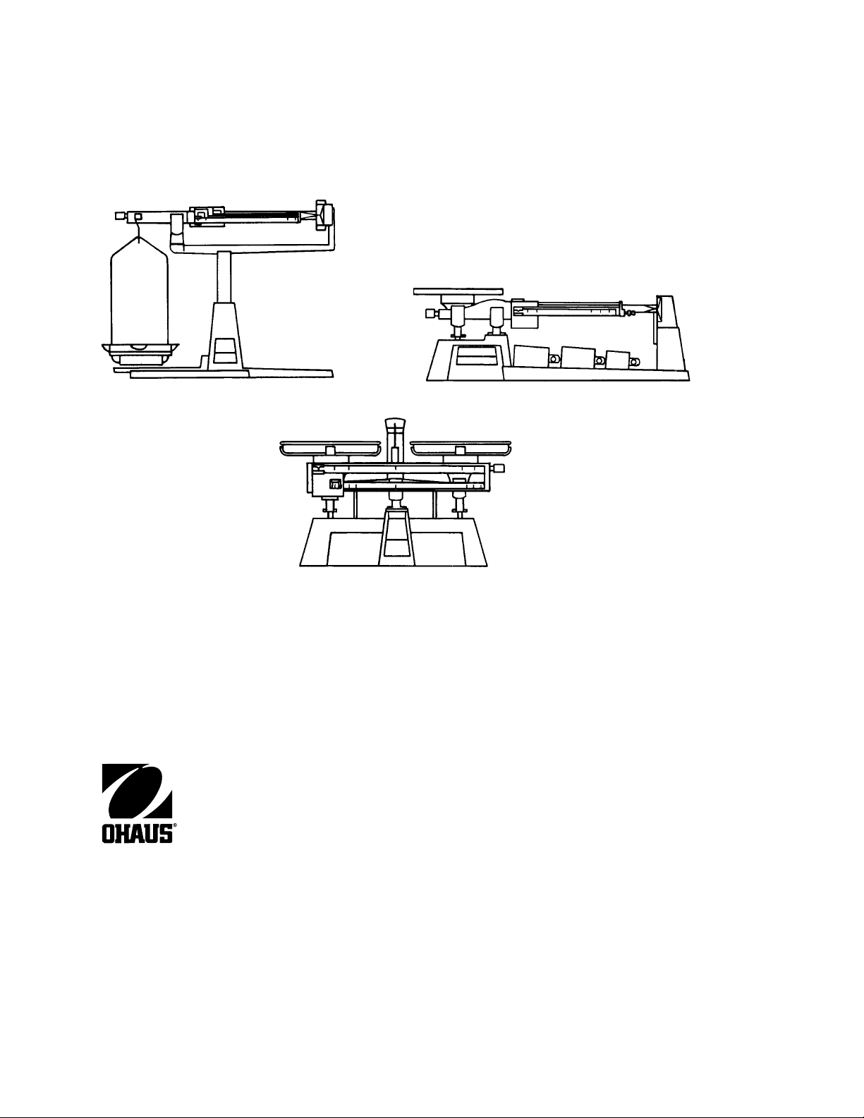
Figure 5-2. Models 310 and 311 Balance Drawing. 5-5/5-6

CHAPTER 5 DRAWINGS
Figure 5-3. Series 1200 Balance Drawing. 5-7/5-8

CHAPTER 5 DRAWINGS
Figure 5-4. Harvard Trip Balance Drawing. 5-9/5-10

MECHANICAL BALANCES P/N 79815-01
 Loading...