


TABLE OF CONTENTS
Page
PREFACE ................................................................ 4
FEATURES AND BENEFITS................................... 4
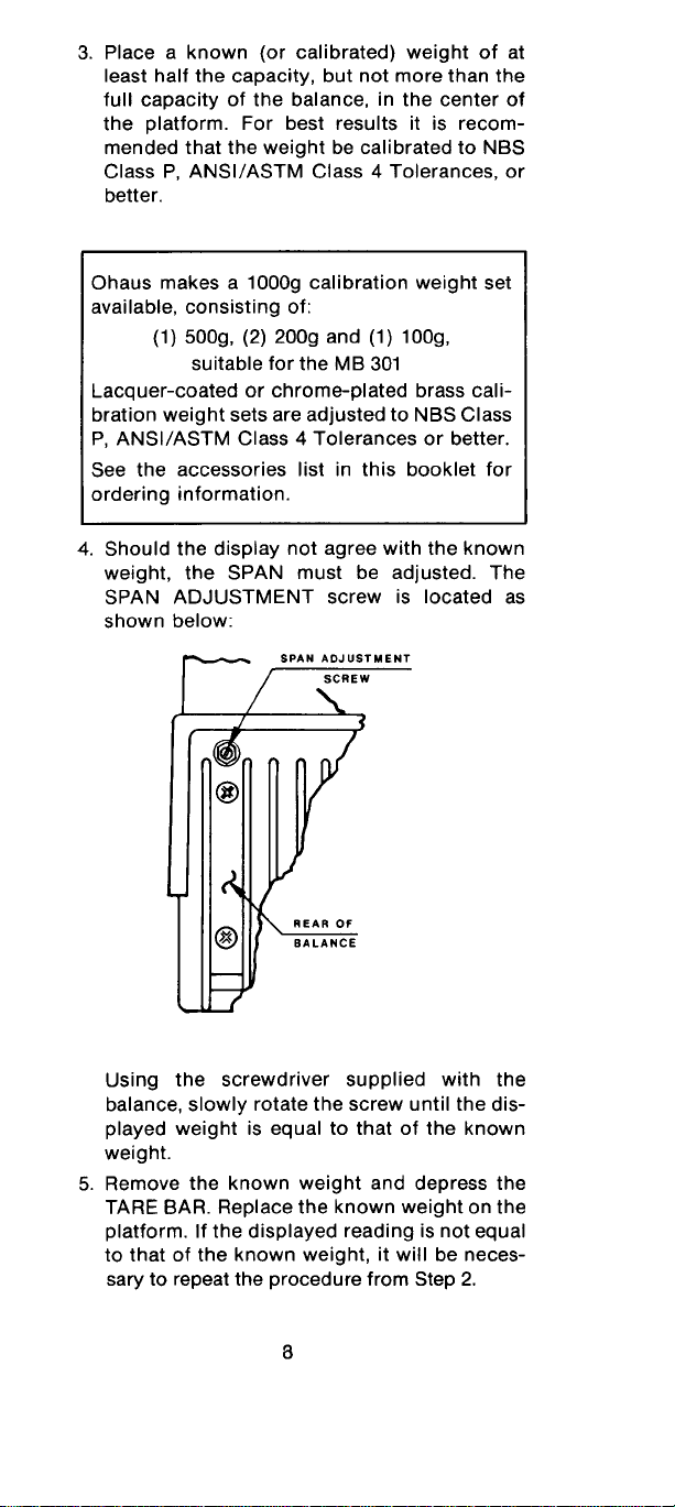
SET UP
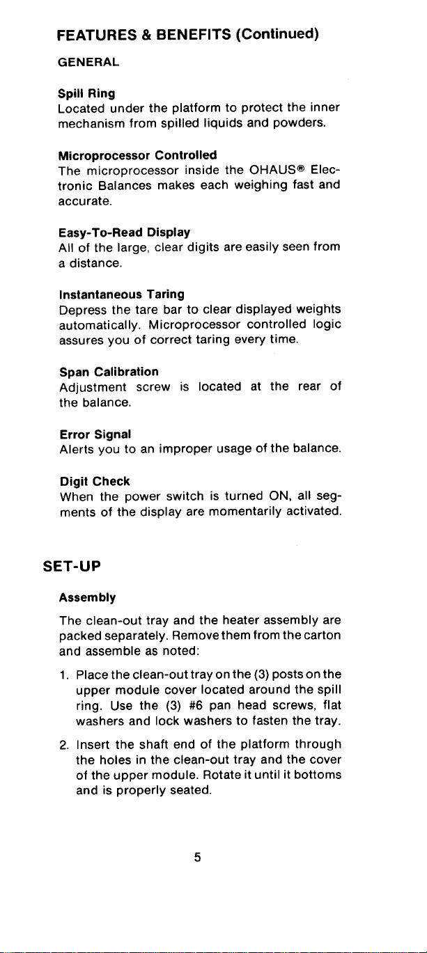
Assembly .............................................................. 5
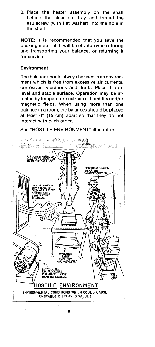
Environment.......................................................... 6
Power Requirements ............................................ 7
Segment Check .................................................... 7
Span Adjustment................................................... 7
Procedure ............................................................. 7
Coarse Calibration................................................9
OPERATION
Determining Moisture Content............................ 12
Drying Information............................................... 13
Weighing Unknowns...........................................14
Taring Displayed Weights................................... 14
Batching (Or Compounding)...............................15
Checkweighing.................................................... 15
INTERFACING....................................................... 15
CARE AND MAINTENANCE
Voltage Setting.................................................... 17
Location of Fuses................................................ 19
Cleaning.............................................................. 19
ACCCESSORIES................................................... 20
REPLACEMENT PARTS.......................................20
SERVICE INFORMATION.....................................20
TROUBLESHOOTING........................................... 21
WARRANTY........................................................... 22
SPECIFICATIONS.................................................23
The information contained in this booklet is
believed to be correct at the time of publication.
Ohaus Scale Corporation assumes no liability
resulting from the use or misuse of this material.
~ Ohaus Scale Corporation 1986, all rights reserved.
3


Ohaus Corporation
The pages you are about to
view are for an accessory
which is no longer available
June 8, 2000
29 Hanover Road
Florham Park NJ
07932-0900

Security Device
OBSOLETE, NO LONGER AVAILABLE
Accessory
P/N 76288-00
Installation InstructionsInstallation Instructions
Installation Instructions
Installation InstructionsInstallation Instructions
The Security Device accessory kit is designed to protect OHAUS® balances against
theft. Before installing this accessory, carefully read these instructions. If assistance
is needed, contact Ohaus Corporation:
• In the U.S., call toll-free at 1-800-526-0659.
• In New Jersey, call 1-201-377-9000.

INSTALLATIONINSTALLATION
INSTALLATION
INSTALLATIONINSTALLATION
Figure 1 shows the typical lock and
cable assembly for balances requiring
the Security Device Bushing to be installed in the balance.
WARNING:WARNING:
WARNING: ALWAYS DISCONNECT
WARNING:WARNING:
POWER BEFORE OPENING BALANCE.
CT Series, C305, C505 andCT Series, C305, C505 and
CT Series, C305, C505 and
CT Series, C305, C505 andCT Series, C305, C505 and
S200S200
S200
S200S200
1. Remove Battery Cover and
Battery Pack.
2. Remove Hole Plug.
3. Install Security Device
Bushing in hole and install
Lock and Cable as in Figure 1.
Security
Device
Bushing
Balance
Case
1
Cable
Lock
Figure 1Figure 1
Figure 1
Figure 1Figure 1
4. Reassemble.
Port-O-Gram BalancesPort-O-Gram Balances
Port-O-Gram Balances
Port-O-Gram BalancesPort-O-Gram Balances
1. Remove screws which secure Battery Cover. Remove cover and battery pack.
2. Remove Hole Plug.
3. Install Security Device Bushing in
hole and install Lock and Cable as
in Figure 1.
4. Reassemble.
2
2
3
2
3
1

E Series, Galaxy, GT400,E Series, Galaxy, GT400,
E Series, Galaxy, GT400,
E Series, Galaxy, GT400,E Series, Galaxy, GT400,
GT4000 and GT8000 OnlyGT4000 and GT8000 Only
GT4000 and GT8000 Only
GT4000 and GT8000 OnlyGT4000 and GT8000 Only
1. Remove screws and washers which
secure cover to base and lift the
cover. Be careful not to pull any
wires, cables or connectors going
from the cover to the base.
2. Remove Hole Plug.
3. Install Security Device Bushing in
hole and install Lock and Cable as
in Figure 1.
4. Reassemble.
PRECISION PRECISION
PRECISION
PRECISION PRECISION
1. Remove the Draft Shield (if installed), Pan and Pan Support.
2. Remove the three screws
which secure cover to
base and lift cover off.
3. Remove Hole Plug.
4. Install Security Device Bushing in hole and install Lock and
Cable as in Figure 1.
Standard Standard
Standard
Standard Standard
Balances Balances
Balances
Balances Balances
1
23
2
1
1
3
5. Reassemble.
MB200, PRECISION MB200, PRECISION
MB200, PRECISION
MB200, PRECISION MB200, PRECISION
All GT Series Except GT400,All GT Series Except GT400,
All GT Series Except GT400,
All GT Series Except GT400,All GT Series Except GT400,
GT4000 and GT8000GT4000 and GT8000
GT4000 and GT8000
GT4000 and GT8000GT4000 and GT8000
The Security Device Bushing is not required on these balances.
To install, simply pass the Cable through
the hole in the level indicator on the rear
of the balance.
Plus Plus
Plus
Plus Plus
andand
and
andand
Rear of
balance
Pass Cable through hole.
3

MB 300, MB301 and B Series BalancesMB 300, MB301 and B Series Balances
MB 300, MB301 and B Series Balances
MB 300, MB301 and B Series BalancesMB 300, MB301 and B Series Balances
The Security Device Bushing is not required on these balances.
To install, simply pass the Cable through
the hole in the pad between two heat
sink fins on the rear of the balance.
Rear of
balance
Pass Cable
through hole.
Other BalancesOther Balances
Other Balances
Other BalancesOther Balances
The Security Device may be used with other balances however, a 1/2” diameter hole
may need to be drilled in the balance to accept the Security Device Bushing. If so, the
following precautions must be taken:
PRECAUTIONSPRECAUTIONS
PRECAUTIONS
PRECAUTIONSPRECAUTIONS
• Select a location on the balance where drilling will not
damage any internal components.
• If uncertain, contact balance manufacturer for recommendations.
• Make sure that chips caused by drilling do not get into
the mechanism of the balance.
• Verify that operation of balance will not be obstructed
when Security Device Bushing is installed in the balance.
OHAUS® is the registered trademark of Ohaus Corporation as are the following
trademarks: CENT-O-GRAM® , CHECK-O-GRAM® , DEC-O-GRAM® , DIAL-O-GRAM® ,
PRIMER® , 5-0-5® , and 10-10® .
OHAUS CORPORATIONOHAUS CORPORATION
OHAUS CORPORATION
OHAUS CORPORATIONOHAUS CORPORATION
P.O. Box 900
29 Hanover Road
Florham Park, N.J. 07932, USA
Tel: 201-377-9000
Telex: 6853191 OHAUS UW
Fax: 201-593-0359
With other offices in England, Mexico, Canada,
Japan, Germany, France, Switzerland
®
P/N 76438-00 R0793 © Ohaus Corporation 1993, all rights reserved.
 Loading...