

Page 1

General-PurposeGeneral-Purpose
General-Purpose
General-PurposeGeneral-Purpose
Scale BasesScale Bases
Scale Bases
Scale BasesScale Bases
Models LB30, LB60,Models LB30, LB60,
Models LB30, LB60,
Models LB30, LB60,Models LB30, LB60,
PL100, PL150PL100, PL150
PL100, PL150
PL100, PL150PL100, PL150
Instruction ManualInstruction Manual
Instruction Manual
Instruction ManualInstruction Manual
© Ohaus Corporation 1994, all rights reserved.
Page 2

TABLE OF CONTENTSTABLE OF CONTENTS
TABLE OF CONTENTS
TABLE OF CONTENTSTABLE OF CONTENTS
INTRODUCTION ........................................................................................ 3
DESCRIPTION ........................................................................................... 3
UNPACKING...............................................................................................4
INSTALLATION .......................................................................................... 4
Load Cell Cable Connections......................................................4
Connection to Ohaus I10 Indicator .........................................4
Connection to Ohaus Models I5S, I20W and I150 Indicators .4
Connection to non Ohaus Indicators ......................................5
Leveling the Scale Base .............................................................6
Calibration...................................................................................6
CARE AND MAINTENANCE ......................................................................7
REPLACEMENT PARTS ............................................................................ 7
SERVICE INFORMATION .......................................................................... 7
SPECIFICATIONS ...................................................................................... 8
LIMITED WARRANTY ................................................................................ 9
Page 3
INTRODUCTIONINTRODUCTION
INTRODUCTION
INTRODUCTIONINTRODUCTION
This manual covers installation, maintenance, replacement parts and service
information for Ohaus General-Purpose Scale Bases, Models LB30, LB60, PL100
and PL150. To ensure proper operation of the Scale Base, please read this manual
completely.
DESCRIPTIONDESCRIPTION
DESCRIPTION
DESCRIPTIONDESCRIPTION
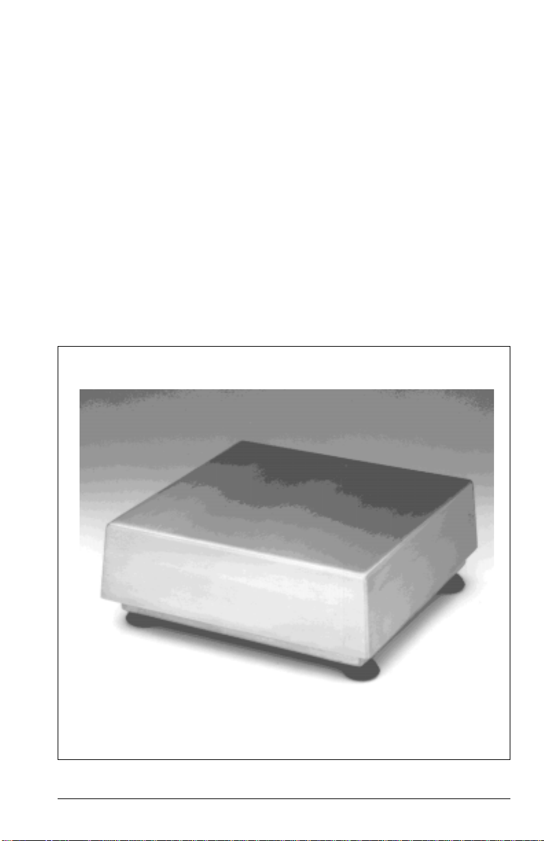
The Ohaus General Purpose Scale Bases are rugged, precision manufactured,
and, consists of a stainless steel platform, an Aluminum structure,and an anodized
Aluminum load cell. These scale bases are designed to interface with Ohaus
electronic indicators and work with other compatible indicators as well.
All Ohaus bases are ruggedly built with overload protection to take the rough
handling encountered in a busy industrial environment, yet remain highly precise.
They meet NIST Handbook 44 Class III and Consumer and Corporate Affairs
Canada General Class requirements for legal for trade applications.
General-Purpose Scale Base
3
Page 4

UNPACKINGUNPACKING
UNPACKING
UNPACKINGUNPACKING
Carefully unpack and remove the Scale Base from the packing material.
NOTENOTE
NOTE: It is recommended that you save the packing material. It will be of value
NOTENOTE
when storing and/or transporting the Scale Base.
INSTALLATION
Load Cell Cable ConnectionsLoad Cell Cable Connections
Load Cell Cable Connections
Load Cell Cable ConnectionsLoad Cell Cable Connections
Connect the load cell cable of the Scale Base to the indicator as follows:
NOTE:
These steps may be omitted if the Scale Base was purchased with the I5S as a
Model BxxxS Bench Scale.
Connection to Ohaus Model I10 IndicatorConnection to Ohaus Model I10 Indicator
Connection to Ohaus Model I10 Indicator
Connection to Ohaus Model I10 IndicatorConnection to Ohaus Model I10 Indicator
Plug the load cell cable connector directly into the receptacle at the rear of the
indicator.
Connection to Ohaus Models I5S, I20W and I150 IndicatorsConnection to Ohaus Models I5S, I20W and I150 Indicators
Connection to Ohaus Models I5S, I20W and I150 Indicators
Connection to Ohaus Models I5S, I20W and I150 IndicatorsConnection to Ohaus Models I5S, I20W and I150 Indicators
The load cell cable must be hard wired to the terminal block of the indicator. This
will require removal of the load cell cable connector and preparation of the load cell
wires as illustrated below.
Load Cell Cable Wire Preparation
4
Page 5

Following the instructions provided with the indicator, wire the load cell cable to the
terminal block as shown in the table below.
WIRE COLOR DESIGNATION
Green +Excitation
Black - Excitation
Red +Signal
White - Signal
Braided Shield Ground
Yellow Unused
Blue Unused
Be sure to insulate the braided shield and the unused yellow and blue wires to
prevent electrical shorting to the indicator's circuit board.
Connection to non Ohaus IndicatorsConnection to non Ohaus Indicators
Connection to non Ohaus Indicators
Connection to non Ohaus IndicatorsConnection to non Ohaus Indicators
Connections should be made according to the instructions provided with the
indicator.
5
Page 6

Leveling the Scale BaseLeveling the Scale Base
Leveling the Scale Base
Leveling the Scale BaseLeveling the Scale Base
1. Place the Scale Base in the intended use location on a stable, level surface.
2. Remove the stainless steel Platform from the top of the Scale Base to expose
the circular Spirt Level mounted in the top of the sub-platform.
3. If the bubble is not centered in the scribed circle of the Spirit Level, loosen
the Locking Nuts and adjust the Leveling Feet until the bubble is centered.
4. Tighten the Locking Nuts and replace the Platform.
SPIRIT LEVEL
INDICATOR
Scale Base (Platform Removed)
CalibrationCalibration
Calibration
CalibrationCalibration
Refer to the Indicator Instruction Manual for the system calibration procedure.
6
Page 7

CARE AND MAINTENANCECARE AND MAINTENANCE
CARE AND MAINTENANCE
CARE AND MAINTENANCECARE AND MAINTENANCE
To keep the Scale Base operating properly, it should be kept free from foreign
materials. If necessary, a cloth dampened with water and a mild detergent may be
used. Wipe the unit dry with a soft cloth.
REPLACEMENT PARTSREPLACEMENT PARTS
REPLACEMENT PARTS OHAUS
REPLACEMENT PARTSREPLACEMENT PARTS
Part No.
Stainless Steel Platforms
LB30 and LB60 12" x 12" 76689-02
PL100 and PL150 18" x 18" 76643-02
Plug 90603-02
Adjusting Foot LB30 and LB60 76635-01
PL100 and PL150 76635-00
SERVICE INFORMATIONSERVICE INFORMATION
SERVICE INFORMATION
SERVICE INFORMATIONSERVICE INFORMATION
For service assistance in the United States, please call Ohaus Corporation toll-free
at (800) 526-0659. An Ohaus Product Service Specialist will be available to help you.
7
Page 8

SPECIFICATIONSSPECIFICATIONS
SPECIFICATIONS
SPECIFICATIONSSPECIFICATIONS
MODELMODEL
MODEL
MODELMODEL
LB30LB30
LB30
LB30LB30
LB60LB60
LB60
LB60LB60
PL100PL100
PL100
PL100PL100
PL150PL150
PL150
PL150PL150
Capacity (lb/kg) 30/13.5 60/27.2 100/45.3 150/68
Readability (lb/kg)** 0.01/0.005 0.02/0.01 0.02/0.01 0.05/0.05
Platform size (in/cm) 12 x 12/30.5 x 30.5 18 x 18/45.7 x 45.7
Safe overload* 150%
Maximum overload* 300%
Linearity* 0.02%
Repeatabilty* 0.01%
Shift accuracy* 0.025%
(50% Capacity/50% Distance)3 seconds
Load cell excitation (VDC) 5 to 15
Output impedance (ohms) 350
Output at rated load (mV/V) 2
Temperature range 32° to 104°F/0° to 40° C (Non type approved)
50° to 104°F/10° to 40° C (Type approved)
Net weight (lb/kg) 12/5.5 27.2/12.4
Shipping weight (lb/kg) 14/6.4 33/15
NIST HB44 Class III
NIST/NTEP n
= 3000 n
max
=5000
max
n
max
= 3000
NTEP Certificate of Conformance
No. 88-203 No. 88-228
Consumer and Corporate
Class Affairs Canada Notice of Approval No. S.WA4467
Weights and Measures Act and Regulations General
* Specifications
are given as a percent of the rated load.
** In Legal for Trade applications, readability is limited to Capacity/n
max
8
Page 9

LIMITED WARRANTYLIMITED WARRANTY
LIMITED WARRANTY
LIMITED WARRANTYLIMITED WARRANTY
Ohaus products are warranted against defects in materials and workmanship
from the date of delivery through the duration of the warranty period. During the
warranty period Ohaus will repair, or, at its option, replace any component(s)
that proves to be defective at no charge, provided that the product is returned,
freight prepaid, to Ohaus.
This warranty does not apply if the product has been damaged by accident or
misuse, exposed to radioactive or corrosive materials, has foreign material
penetrating to the inside of the product, or as a result of service or modification
by other than Ohaus. In lieu of a properly returned warranty registration card,
the warranty period shall begin on the date of shipment to the authorized
dealer. No other express or implied warranty is given by Ohaus Corporation.
Ohaus Corporation shall not be liable for any consequential damages.
As warranty legislation differs from state to state and country to country, please
contact Ohaus or your local Ohaus dealer for further details.
9
Page 10

Ohaus Corporation
29 Hanover Road,
Florham Park, NJ 07932, USA
Tel: (201) 377-9000,
Telex: 6853191 Ohaus UW, Fax: (201) 593-0359
Ohaus Europe Ltd.
Cottenham, Cambridge, ENGLAND
Tel: +44 954 251343, Fax: +44 954 250205
Ohaus GmbH
Giessen, GERMANY
Tel: +49-(0) 641-71023, Fax: +49 (0) 641-71025
Ohaus de Mexico, S.A. de C.V.
Mexico, D.F. MEXICO
Tel: +52-5-586-4905, +52-5-752-5746, Fax: +52-5-754-7024
Ohaus Corporation
Mississauga, Ontario, CANADA
Tel: (905) 566-5859, Fax: (905) 277-1232
Ohaus s.a.r.l.
Viroflay, FRANCE
Tel: +33-1-39-24-0193, Fax: +33-1-39-24-0194
Ohaus Japan Division
Takarazuka, JAPAN
Tel: +81-797-74-2479, Fax: +81-797-74-2343
Ohaus Instrumentos S.A.
Barcelona, SPAIN
Tel: & Fax: +34 3 223 3440
P/N 77669-01 R1294
 Loading...