


EB SERIES SCALES
SERVICE MANUAL
Ohaus Corporation 7 Campus Drive, Suite 310, Parsippany, NJ 07054 (973) 377-9000
EB SERIES SCALES
SERVICE MANUAL
The information contained in this manual is believed to be accurate at the time of publication, but Ohaus Corporation assumes no liability arising from the use or misuse of this material. Reproduction of this material is strictly prohibited.
Material in this manual is subject to change.
© Copyright 2011 Ohaus Corporation, all rights reserved. ® Registered trademark of Ohaus Corporation.

TABLE OF CONTENTS
CHAPTER 1 GETTING STARTED |
Page No. |
||
1 |
Introduction .............................................................................................................. |
1-1 |
|
1.1 |
Service Facilities ...................................................................................................... |
1-1 |
|
1.2 |
Tools and Test Equipment Required ........................................................................ |
1-2 |
|
1.2.1 Standard Tools and Test Equipment ................................................................. |
1-2 |
||
1.2.2 |
Special Tools .................................................................................................... |
1-2 |
|
1.3 |
Calibration Masses Required ................................................................................... |
1-2 |
|
1.4 |
Service Strategy....................................................................................................... |
1-2 |
|
1.5 |
Specifications........................................................................................................... |
1-3 |
|
1.6 |
Scale Settings.......................................................................................................... |
1-4 |
|
CHAPTER 2 DIAGNOSIS |
|
||
2. |
Diagnosis ................................................................................................................. |
2-1 |
|
2.1 |
Scale Setup and Examination .................................................................................. |
2-1 |
|
2.2 |
Preliminary Checks .................................................................................................. |
2-1 |
|
2.3 |
Troubleshooting Tables............................................................................................ |
2-1 |
|
2.4 |
EB Series Scales Error Code Table ......................................................................... |
2-5 |
|
2.5 |
Testing the AC Adapter............................................................................................ |
2-6 |
|
2.6 |
Testing the Membrane Switch .................................................................................. |
2-6 |
|
2.7 |
Testing the Load Cell Assembly ............................................................................... |
2-7 |
|
2.7.1 |
Resistance Test ................................................................................................ |
2-7 |
|
2.7.2 Excitation and Output Voltage Test ................................................................... |
2-7 |
||
2.8 |
Testing the Main PC Board ...................................................................................... |
2-9 |
|
2.8.1 Main PC Board Voltage Measurements ............................................................ |
2-9 |
||
2.8.2 |
Simulator Testing .............................................................................................. |
2-9 |
|
|
|
2.8.2.1 General Load Test.................................................................................. |
2-10 |
|
|
2.8.2.2 Calibration Test ...................................................................................... |
2-10 |
2.9 |
Testing the Battery ................................................................................................. |
2-11 |
|
2.9.1 Precautions for Battery Handling..................................................................... |
2-11 |
||
2.9.2 |
Battery Tests................................................................................................... |
2-11 |
|
CHAPTER 3 REPAIR PROCEDURES |
|
||
3. |
Repair Procedures ................................................................................................... |
3-1 |
|
3.1 |
Removing Top Housing............................................................................................ |
3-1 |
|
3.2 |
Replacing The Membrane Switch............................................................................. |
3-2 |
|
3.3 |
Main Printed Circuit Board ....................................................................................... |
3-4 |
|
3.3.1 Main Printed Circuit Board Replacement .......................................................... |
3-4 |
||
3.3.2 Display Printed Circuit Board Replacement....................................................... |
3-7 |
||
3.3.3 |
LCD Replacement............................................................................................. |
3-8 |
|
3.4 |
Replacing the Load Cell Assembly (with Frame) ...................................................... |
3-9 |
|
3.5 |
Replacing the Load Cell Component...................................................................... |
3-11 |
|
3.5.1 Overload Protection Stop Adjustment ............................................................. |
3-12 |
||
3.6 |
Replacing the Battery............................................................................................. |
3-14 |
|
CHAPTER 4 FINAL TESTING & CALIBRATION |
|
||
4.1. |
Performance Tests................................................................................................... |
4-1 |
|
4.1.1 |
Segment Display Test....................................................................................... |
4-1 |
|
4.1.2 |
Repeatability Test ............................................................................................. |
4-1 |
|
4.1.3 |
Off-Center Load Test ........................................................................................ |
4-3 |
|
4.1.4 |
Linearity Test .................................................................................................... |
4-4 |
|
4.2 |
Calibration................................................................................................................ |
4-6 |
|
4.2.2 |
Span Calibration ............................................................................................... |
4-6 |
|
EB Series Scales Service Manual |
i |
Ohaus Corporation www.ohaus.com |

TABLE OF CONTENTS
CHAPTER 5 DRAWINGS AND PARTS LISTS |
Page No. |
|
5. |
Drawings and Parts Lists.......................................................................................... |
5-1 |
Appendix A SERVICE MODES |
|
|
A.1 |
Entering the Service Menu ..................................................................................... |
A-1 |
A.2 |
Service Calibration .................................................................................................. |
A-1 |
A.3 |
Scale Configuration................................................................................................. |
A-2 |
LIST OF TABLES
TABLE NO. |
TITLE |
Page No. |
1-1 |
Calibration Masses .............................................................................................. |
1-2 |
1-2 |
Specifications ...................................................................................................... |
1-3 |
1-3 |
Menu Structure .................................................................................................... |
1-4 |
2-1 |
Scale Will Not Turn On With AC Adapter ............................................................. |
2-1 |
2-2 |
Scale Will Not Turn On Using Battery Power ....................................................... |
2-2 |
2-3 |
Scale Does Not Respond To Front Panel Controls .............................................. |
2-3 |
2-4 |
No Display or Partial Display ............................................................................... |
2-3 |
2-5 |
Balance Reading Incorrect or Unstable................................................................ |
2-4 |
2-6 |
Cannot Calibrate the Scale .................................................................................. |
2-4 |
2-7 |
EB Series Scales Error Codes ............................................................................. |
2-5 |
2-8 |
Membrane Switch Pin Connections ..................................................................... |
2-6 |
2-9 |
Load Cell Resistance Reading............................................................................. |
2-7 |
2-10 |
Load Cell Output Reading.................................................................................... |
2-8 |
3-1 |
Load Cell Screw Torque Settings....................................................................... |
3-11 |
3-2 |
Load Cell Overload Protection Stop Gap Settings.............................................. |
3-13 |
4-1 |
Repeatability Worksheet ...................................................................................... |
4-2 |
4-2 |
Calibration Points................................................................................................. |
4-6 |
5-1 |
EB Series Scales: Housing and Parts.................................................................. |
5-3 |
A-1 |
Scale Resolution Settings ................................................................................... |
A-2 |
|
LIST OF ILLUSTRATIONS |
|
FIGURE NO. |
TITLE |
Page No. |
2-1 |
Membrane Switch Connector............................................................................... |
2-6 |
2-2 |
EB Interconnections: Version 1............................................................................ |
2-8 |
2-3 |
EB Interconnections: Version 2............................................................................ |
2-8 |
3-1 |
Retaining Screws on Bottom of Housing.............................................................. |
3-1 |
3-2 |
Removing the Top Housing ................................................................................. |
3-2 |
3-3 |
Ribbon Cable from Main PCB to Display PCB ..................................................... |
3-2 |
3-4 |
Disconnecting the Membrane Switch Cable......................................................... |
3-3 |
3-5 |
Battery Terminal Connector ................................................................................. |
3-4 |
3-6 |
Main PC Board Screws and Washers .................................................................. |
3-4 |
3-7 |
Main PCB, Version 1 ........................................................................................... |
3-5 |
3-8 |
Main PCB, Version 2 ........................................................................................... |
3-5 |
3-9 |
Display Cable installed on Main PCB................................................................... |
3-5 |
3-10 |
Ribbon Cable from Main PCB to Display PCB ..................................................... |
3-7 |
3-11 |
Disconnecting Membrane Switch Cable from Display PCB .................................. |
3-7 |
3-12 |
Screws connecting Display PCB to Bottom Housing............................................ |
3-7 |
3-13 |
Feet on Bottom of Scale ...................................................................................... |
3-9 |
3-14 |
Load Cell Retaining Screw Locations................................................................... |
3-9 |
3-15 |
Load Cell Mounting Bolt Locations..................................................................... |
3-11 |
3-16 |
Load Cell Frame Mounting Bolt Locations ......................................................... |
3-12 |
Ohaus Corporation www.ohaus.com |
ii |
EB Series Scales Service Manual |

TABLE OF CONTENTS
FIGURE NO. |
TITLE |
Page No. |
3-17 |
Overload Stop Locations.................................................................................... |
3-12 |
3-18 |
Battery Connections .......................................................................................... |
3-14 |
4-1 |
Segment Display ................................................................................................. |
4-1 |
4-2 |
Off-Center Load Test Weight Locations ............................................................... |
4-2 |
5-1 |
EB Series Scales: Housing and Parts .................................................................. |
5-2 |
EB Series Scales Service Manual |
iii |
Ohaus Corporation www.ohaus.com |

TABLE OF CONTENTS
Ohaus Corporation www.ohaus.com |
iv |
EB Series Scales Service Manual |
CHAPTER 1 GETTING STARTED
1. INTRODUCTION
This service manual contains instructions for the diagnosis and repair work to be performed by Ohaus Dealers or Ohaus authorized service centers. Knowledge of the operation of the Scale is assumed. Instruction manuals may be required with this service manual. For complete information on operation, refer to the Instruction Manual.
This manual covers maintenance on the following:
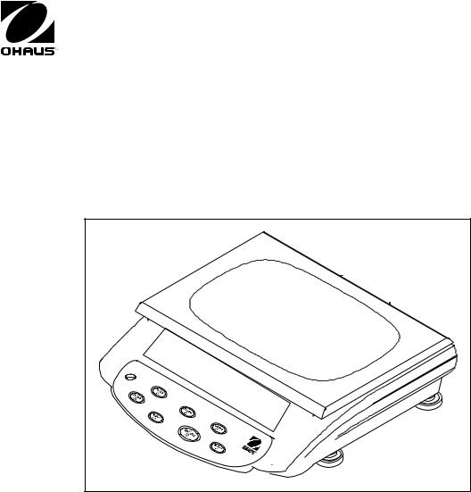
EB Series Scales, Models EB3, EB6, EB15 and EB30
The contents of this manual are contained in five chapters and two Appendixes with service menu and calibration instructions.
Chapter 1 Introduction - Contains information about service facilities, tools, test equipment, test masses, service strategy, specifications, and setup.
Chapter 2 Diagnosis - Contains information on problem verification, scale examination, preliminary checks, troubleshooting tables, testing procedures, and an interconnection diagram.
Chapter 3 Repair Procedures - Contains detailed repair procedures for all major components.
Chapter 4 Final Testing - Contains performance tests, and calibration.
Chapter 5 Parts Lists - Contains overall views identifying all major serviceable replacement components with associated parts lists.
Appendix A Service Modes- Contains Configuration, Capacity and Readability for the EB Series Scales in a service mode.
Appendix B Service Calibration - Contains Service Calibration instructions.
1.1SERVICE FACILITIES
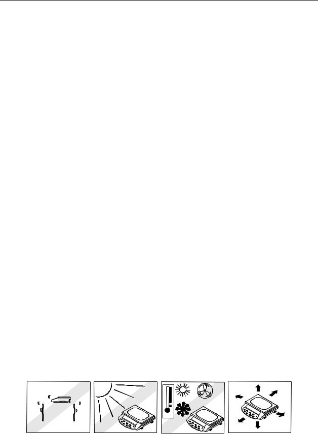
To service a scale, the service area should meet the following requirements:
Meet scale specifications for temperature environmental requirements.
Be free of vibrations such as fork lift trucks close by, large motors, air currents or drafts from air conditioning/heating ducts, open windows, people walking by, fans, etc.
Be clean and free of excessive dust.
Work surface must be stable and level.
Scale must not be exposed to direct sunlight or radiating heat sources.
Use an approved Electro-Static Device.
|
|
|
|
|
|
|
|
|
|
|
|
|
|
|
|
|
|
|
|
|
|
|
|
|
|
|
|
|
|
|
|
|
|
|
|
|
|
|
|
|
|
EB Series Scales Service Manual |
1-1 |
|
|
|
|
|
Ohaus Corporation www.ohaus.com |
||||||

CHAPTER 1 GETTING STARTED
1.2 TOOLS AND EQUIPMENT
1.2.1Standard Tools and Test Equipment
The service shop should contain the following equipment:
1.Digital Voltmeter (DVM).
2.Standard Electronics tool kit.
3.Desk magnifier on a stand.
4.Grounding mat and clip.
5.Razor blades.
1.2.2Special Tools
To service the Ohaus EB Series Scales, the following equipment is recommended:
1.A Load Cell Simulator.
2.AC Adapter, 220 V, 60 Hz (US) Ohaus P/N 80120000
3.AC Adapter, 230 V, 50 Hz (EU) Ohaus P/N 80120001
4.AC Adapter, 230 V, 50 Hz (GB) Ohaus P/N 80120002
5.AC Adapter, 240 V, 50 Hz (AU) Ohaus P/N 80120003
6.AC Adapter, 100 V, 50 Hz (JP) Ohaus P/N 80120004
7.AC Adapter, 230 V, 50 Hz (KR) Ohaus P/N 80120005 NOTE: Adapters required for servicing are location dependent.
1.3CALIBRATION MASSES REQUIRED
The masses required to test the EB Series Scales must meet the requirements of ASTM Class 4 or OIML Class F2. The mass values are listed in Table 1-1.
TABLE 1-1. CALIBRATION MASSES
MODEL |
Calibration Masses |
|
Totaling |
||
|
||
|
|
|
EB3 |
3kg |
|
EB6 |
6kg |
|
EB15 |
15kg |
|
EB30 |
30kg |
|
|
|
Note: The EB Scales can be calibrated over a wide range, however, it is recommended that the calibration mass used is at or near the full capacity of the scale for maximum accuracy.
1.4 SERVICE STRATEGY
The repair method for the EB Series Scales is the direct substitution of major assemblies. The available repair parts are listed in Table 5-1.
The EB Series Scales contain 6 major replaceable assemblies: Top Housing, Membrane Switch, Load Cell Assembly with Frame, Lead Acid Rechargeable Battery, Display PC Board with LCD and the Main PC Board.
Note: The Load Cell and LCD may also be ordered and replaced separately.
Ohaus Corporation www.ohaus.com |
1-2 |
EB Series Scales Service Manual |
CHAPTER 1 GETTING STARTED
1.5SPECIFICATIONS
TABLE 1-2. SPECIFICATIONS
Model |
EB3 |
|
EB6 |
|
EB15 |
|
EB30 |
|
|
|
|
|
|
|
|
Capacity x Readability |
3 kg x 0.0001 kg |
|
6 kg x 0.0002 kg |
|
15 kg x 0.0005 kg |
|
30 kg x 0.001 kg |
|
3000 g x 0.1 g |
|
6000g x 0.2g |
|
15000g x 0.5g |
|
30000g x 1g |
|
6.6 lb x 0.0002 lb |
|
13 lb x 0.0005 lb |
|
33 lb x 0.001 lb |
|
66 lb x 0.002 lb |
|
105 x 0.005 oz |
|
208 x 0.01 oz |
|
528 x 0.02 oz |
|
1,056 x 0.05 oz |
|
|
|
|
|
|
|
|
Maximum Displayed |
|
|
|
1:30000 |
|
|
|
Resolution |
|
|
|
|
|
||
|
|
|
|
|
|
|
|
Construction |
|
|
Stainless steel platform, plastic housing |
|
|||
|
|
|
|
|
|||
Weighing Units |
|
|
kg, g, lb, oz |
|
|||
|
|
||||||
Application Modes |
Weighing, Counting, Hi-Lo Check-counting/weighing, Percent, Accumulation |
||||||
|
|
||||||
Display |
1-Window backlit LCD display, 25.4mm / 1” high, 6-digit, 7-segment |
||||||
|
|
||||||
Display Indicators |
Stability, Center of Zero, Gross, Tare, Battery Status, Hi-OK-Lo, Units |
||||||
|
|
||||||
Keyboard |
7-function membrane switch: M+, Units, Zero, Tare, Check, Count, % |
||||||
|
|
|
|
|
|||
Zero Range |
|
|
4% of Full Scale Capacity |
|
|||
|
|
||||||
Tare Range |
Full Capacity by Subtraction (except EB15: up to 10kg only) |
||||||
|
|
|
|
|
|||
Stabilization Time |
|
|
< 2 seconds |
|
|||
|
|
|
|
|
|||
Operating Temperature |
|
|
0° to 40° C |
|
|||
|
|
|
|
|
|||
Humidity Range |
|
|
≤ 90% relative humidity, non-condensing |
|
|||
|
|
|
|
|
|||
Power |
|
|
AC Adapter 12V DC / 800mA |
|
|||
|
|
Internal rechargeable lead acid battery |
|
||||
|
|
|
|
||||
|
|
|
|
||||
Battery Life |
|
80 hours continuous use with 12 hour recharge time |
|
||||
|
|
||||||
Calibration |
Automatic external with kg/g mass, factory calibration recovery |
||||||
|
|
||||||
Shipping Protection |
Shipping screw to avoid damage to sensitive components |
||||||
|
|
|
|
|
|||
Safe Overload Capacity |
|
|
120% of capacity |
|
|||
|
|
|
|
|
|||
Platform Size |
|
|
294 x 226 mm / 11.6 x 8.9 in. |
|
|||
|
|
|
|
||||
Scale dimensions |
|
325 x 330.5 x 114 mm / 12.8 x 13 x 4.5 in. (W x D x H) |
|
||||
|
|
|
|
||||
Shipping dimensions |
|
440 x 360 x 160 mm / 17.3 x 14.2 x 6.3 in (W x D x H) |
|
||||
|
|
|
|
|
|||
Net Weight |
|
|
4.2 kg / 9.3 lb |
|
|||
|
|
|
|
|
|||
Shipping Weight |
|
|
5.3 kg / 11.7 lb |
|
|||
|
|
|
|
|
|||
Other Features |
|
|
Auto-Zero Tracking, Filtering Level |
|
|||
|
|
|
|
|
|
|
|
EB Series Scales Service Manual |
1-3 |
Ohaus Corporation www.ohaus.com |
CHAPTER 1 GETTING STARTED
1.6SCALE SETTINGS
The EB scale contains four user-selectable scale settings (Setup mode). These are as follows: Scale Increment, Backlight, Zero Tracking Range, and Filtering. A description of each setting is explained below.
1.To enter the setup mode, press and then release COUNT and M+ at the same time to enter into the user-selectable scale settings.
2.In the Setup mode, press ▲ to step through available settings.
3.Press Enter to accept the displayed setting and proceed to the next parameter.
4.Press Exit to proceed to the next parameter without saving any changes.
Table 1-3. MENU STRUCTURE
|
|
|
|
|
|
|
|
|
|
|
|
|
inC 01 |
EL AU |
AC 2d |
Fil 1 |
|||||||||
|
|
|
|
|
|
|
|
|
|
|
|
|
(mode-dependent |
|
|
AU |
|
|
|
0.5d |
|
|
0 |
||
settings) |
|
|
|
|
|
|
|
|||||
|
|
|
|
|
|
|||||||
|
|
ON |
|
|
|
1d |
|
|
1 |
|||
|
|
|
|
|
|
|
|
|
||||
|
|
|
|
|
|
|
|
|||||
|
|
|
|
OFF |
|
|
|
2d |
|
|
2 |
|
|
|
|
|
|
|
|
|
|||||
|
|
|
|
|
|
|
|
4d |
|
|
3 |
|
|
|
|
|
|
|
|
|
|
||||
|
|
|
|
|
|
(d=scale division) |
|
|
(Levels) |
|||
|
|
|
|
|
|
|
|
|
|
|
|
|
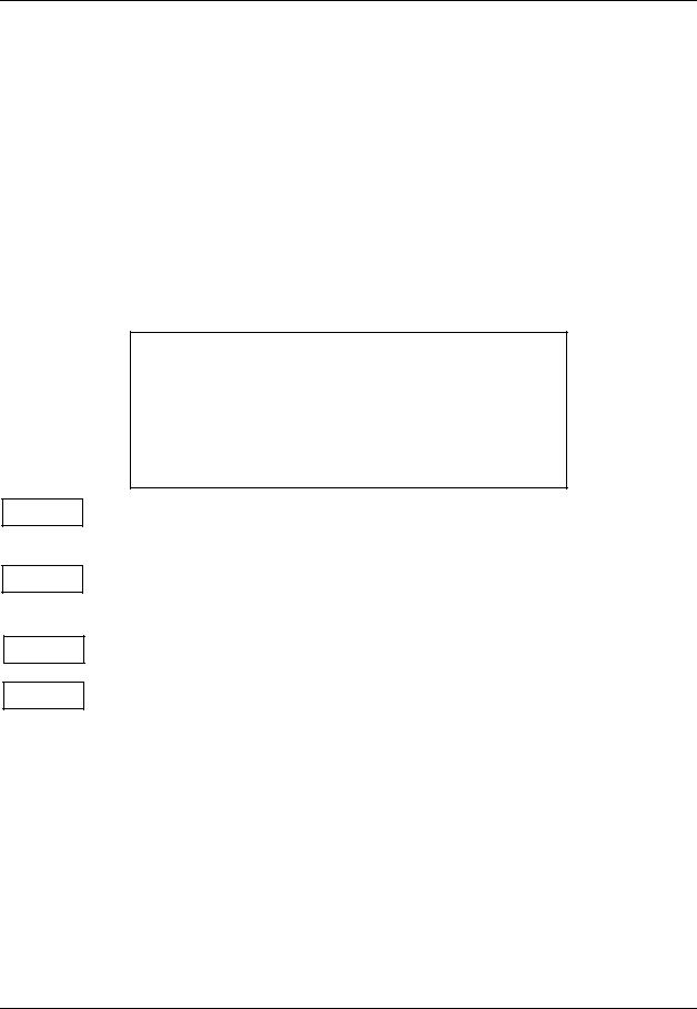
inC 01
EL AU
AC 2d
FiL 1
Scale increment - Sets the displayed scale increment (also known as readability or graduation). Selectable setup values will be model dependent and are equivalent to within 30,000 to 3,000 scale divisions.
Backlight - Sets the activation mode of the backlight.
The following settings are available: AU (Auto-on with items > 9d placed on the Platform or any button pressed; turns off after 5 seconds of inactivity), On, oFF.
Zero Display Range - Sets the range in which the Zero reading is maintained. The following settings are available: 0.5d, 1d, 2d, 4d (d= scale division).
Filtering - Sets the level at which the Stable indication turns on; the higher the setting, the faster the stabilization time.
The following settings are available: 0, 1, 2, 3 (levels).
Ohaus Corporation www.ohaus.com |
1-4 |
EB Series Scales Service Manual |

CHAPTER 2 DIAGNOSIS
2.DIAGNOSIS
This section contains information needed to properly evaluate the reported problem and diagnose its cause.
2.1SCALE SETUP AND EXAMINATION
Set up the scale according to the Instruction manual. Allow the scale to stabilize to room temperature. Examine the scale for signs of corrosion or physical damage.
2.2PRELIMINARY CHECKS
Power up the scale using the customer’s ac adapter. In the case where the scale will not power up, check the ac adapter. Observe and record the error codes and software revision. Record all menu settings as received.
2.3TROUBLESHOOTING TABLES
Troubleshooting tables 2-1 through 2-7 identify actual types of problems that could be encountered with the scale.
The troubleshooting tables refer to the EB Scales Interconnection Diagram, Figure 2-2, to assist in locating the problem.
TABLE 2-1. SCALE WILL NOT TURN ON WITH AC ADAPTER
SYMPTOM |
PROBABLE CAUSE |
REMEDY |
|
|
|
Unit will not turn on |
Adapter defective |
Check the AC adapter voltage output |
with AC adapter |
|
(Section 2.5). If voltage is low or |
supplied |
|
nonexistent, replace the AC adapter. |
|
|
If OK, proceed. |
|
Membrane Switch defective |
Test the Membrane Switch (Section |
|
|
2.6). Replace if necessary |
|
|
(Section 3.2). |
|
|
If the scale fails to turn on with a new |
|
|
Membrane Switch, test the Main PC |
|
|
Board (Section 2.8). If defective, |
|
|
replace the Main PCB (Section 3.3.1). |
|
|
After repair, proceed with Performance |
|
|
Tests in Chapter 4. |
|
|
|
EB Series Scales Series Service Manual |
2-1 |
Ohaus Corporation www.ohaus.com |

CHAPTER 2 DIAGNOSIS
TABLE 2-2. SCALE WILL NOT TURN ON USING BATTERY POWER
SYMPTOM |
PROBABLE CAUSE |
REMEDY |
|
|
|
Scale will not turn on |
Battery discharged or |
Test the battery (Section 2.9). Replace |
using battery power. |
defective. |
if necessary (Section 3.6). |
|
Wiring harness defective or |
Open the scale (Section 3.1). Check |
|
battery clips connection |
voltage at battery contacts first. Check |
|
broken. |
DC voltage at the battery connector on |
|
|
the Main PC Board. Voltage should |
|
|
read approximately 6 Volts DC |
|
|
minimum. If voltage is not present at |
|
|
the connector, disconnect the leads |
|
|
from the battery and make a continuity |
|
|
test between the connectors on the |
|
|
Harness to the connector on the Main |
|
|
PC Board. Resistance should be 0 |
|
|
ohms for the red lead and 0 ohms for |
|
|
the black lead. If an open condition |
|
|
exists, replace wiring and connector as |
|
|
necessary. If OK, proceed. |
|
Membrane Switch defective. |
Test the Membrane Switch (Section |
|
|
2.6). Replace if necessary |
|
|
(Section 3.2). |
|
Main PC Board is defective. |
If the scale fails to turn on with a new |
|
|
Membrane Switch, test the Main PC |
|
|
Board (Section 2.8). If defective, |
|
|
replace the Main PCB (Section 3.3.1). |
|
|
After repair, proceed with Performance |
|
|
Tests in Chapter 4. |
|
|
|
Ohaus Corporation www.ohaus.com |
2-2 |
EB Series Scales Series Service Manual |

CHAPTER 2 DIAGNOSIS
TABLE 2-3. SCALE DOES NOT RESPOND TO FRONT PANEL CONTROLS.
SYMPTOM |
|
PROBABLE CAUSE |
REMEDY |
|
|
|
|
Scale does not |
|
Membrane Switch defective |
Test the Membrane Switch (Section |
respond to front panel |
|
|
2.6). Replace if necessary (Section |
controls. |
|
|
3.2). If membrane switches are OK, |
|
|
|
test the Main PC Board (Section 2.8). |
|
|
|
If defective, replace the Main PCB |
|
|
|
(Section 3.3.1). |
|
|
|
After repair, proceed with Performance |
|
|
|
Tests in Chapter 4. |
|
|
|
|
|
TABLE 2-4. NO DISPLAY OR PARTIAL DISPLAY. |
||
|
|
|
|
SYMPTOM |
|
PROBABLE CAUSE |
REMEDY |
|
|
|
|
Display is not on or |
|
Display PC Board is |
The Display PC Board is replaced as a |
partial characters are |
|
defective or LCD may be |
whole assembly. Check procedures in |
displayed. |
|
defective. |
Tables 2-1, 2-2 and 2-3 first and verify |
|
|
|
that other problems do not exist. |
|
|
NOTE: If the LCD shows |
Replace Display PC Board or LCD. |
|
|
signs of damage such as |
See Repair Procedures 3.3.2 and |
|
|
cracked, dim or partial |
3.3.3. |
|
|
characters, the LCD should |
After repair, proceed with Performance |
|
|
be replaced. |
|
|
|
Tests in Chapter 4. |
|
|
|
|
|
|
|
|
|
EB Series Scales Series Service Manual |
2-3 |
Ohaus Corporation www.ohaus.com |

CHAPTER 2 DIAGNOSIS
TABLE 2-5. BALANCE READING INCORRECT OR UNSTABLE.
SYMPTOM |
|
PROBABLE CAUSE |
REMEDY |
|
|
|
|
Balance reads |
|
Needs calibration. |
Perform Service Calibration in |
incorrectly. |
|
|
Appendix B. If calibration fails, refer to |
Balance reading |
|
|
Table 2-6. |
|
|
|
|
unstable. |
|
Load Cell is damaged. |
Test the Load Cell (Section 2.7). If |
|
|
|
defective replace it (Section 3.4). |
|
|
|
After repair, proceed with Performance |
|
|
|
Tests in Chapter 4. |
|
|
Main PC Board defective. |
Test the Main PC Board (Section 2.8). |
|
|
|
If defective, replace it (Section 3.3). |
|
|
|
After repair, proceed with Performance |
|
|
|
Tests in Chapter 4. |
|
|
|
|
|
TABLE 2-6. CANNOT CALIBRATE THE SCALE. |
||
|
|
|
|
SYMPTOM |
|
PROBABLE CAUSE |
REMEDY |
|
|
|
|
Scale can be turned |
|
Incorrect weights. |
Verify that proper weights are used. |
on but will not |
|
Load cell assembly |
Test the Load Cell (Section 2.7). If |
calibrate. |
|
||
|
defective. |
defective replace it (Section 3.4). |
|
|
|
||
|
|
|
After repair, proceed with Performance |
|
|
|
Tests in Chapter 4. |
|
|
Main PC Board defective |
Test the Main PC Board (Section 2.8). |
|
|
|
If defective, replace it (Section 3.3). |
|
|
|
After repair, proceed with Performance |
|
|
|
Tests in Chapter 4. |
|
|
|
|
Ohaus Corporation www.ohaus.com |
2-4 |
EB Series Scales Series Service Manual |
 Loading...