

Ohaus D52XW50RTR1, D52XW50RTX2, D52XW50RQV3, D52XW50WQR6, D52XW50WQV8 Instruction Manual
...Page 1
Defender Series Base
Service Manual
Page 2

TABLE OF CONTENTS
CHAPTER 1 INTRODUCTION ............................................................................................................................ 2
1.1 Introduction ............................................................................................................................................ 2
1.2 Definition of Signal Warning and Symbols ............................................................................................ 2
1.3 Safety Precaution .................................................................................................................................. 3
1.4 Service Facilities ................................................................................................................................... 3
1.5 Tools and Test Equipment Required ..................................................................................................... 4
1.6 Test Masses Required .......................................................................................................................... 4
1.7 Service Strategy .................................................................................................................................... 4
1.8 Physical Description: Model Defender Series Base .............................................................................. 4
1.9 Specifications ........................................................................................................................................ 5
1.10 How Load Cells Operate ....................................................................................................................... 9
1.11 Load Cell Connection .......................................................................................................................... 10
CHAPTER 2 TROUBLESHOOTING .................................................................................................................. 12
2.1 Troubleshooting ................................................................................................................................... 12
2.1.1 Checking Load Cells for Trouble ..................................................................................................... 12
CHAPTER 3 MAINTENANCE AND REPAIR PROCEDURES .......................................................................... 13
3.1 Preventive Maintenance ...................................................................................................................... 13
3.1.1 Preventive Maintenance Checklist .............................................................................................. 13
3.2 Replacing the Load Cell ...................................................................................................................... 13
3.3 Overload Stop Adjustment .................................................................................................................. 14
CHAPTER 4 TESTING ...................................................................................................................................... 17
4.1 Testing ................................................................................................................................................. 17
4.2 Load Cell Resistance Checks ............................................................................................................. 17
4.3 Calibration with an External Indicator .................................................................................................. 17
4.4 Consistency Check .............................................................................................................................. 18
4.5 Performance Tests .............................................................................................................................. 18
4.5.1 Off Center Load (Shift) Test ............................................................................................................ 19
4.5.2 Adjusting Off Center Load ............................................................................................................... 20
4.5.3 Full Load Test .................................................................................................................................. 21
CHAPTER 5 PARTS IDENTOFICATION ........................................................................................................... 22
5.1 Defender series Base: Carbon Steel model ........................................................................................ 22
5.2 Defender series Base: Stainless Steel model ..................................................................................... 24
APPENDIX A. GLOSSARY ................................................................................................................................ 26
Ohaus Corporation www.ohaus.com i Defender™ Series Bases Service Manual
Page 3

CHAPTER 1 INTRODUCTION
1.1 Introduction
This service manual contains the information needed for diagnosis and repair of Ohaus Defender series Bases.
The contents of this manual are contained in five chapters:
Chapter 1 Introduction – Contains information regarding service facilities, tools and test equipment, test
masses, specifications, service strategy, and the mechanical and electronic operation of the Base.
Chapter 2 Troubleshooting – Provides guidelines for evaluating the condition and performance of a Base
unit, and a standard troubleshooting methodology to follow, as well as a diagnostic guide.
Chapter 3 Maintenance Procedures – Contains preventive maintenance procedures and disassembly, repair
and replacement procedures.
Chapter 4 Testing – Contains guides for operational and performance tests and adjustments.
Chapter 5 Parts Identification – Contains exploded views of Defender series Bases and parts, identifying all
serviceable components with parts lists.
Before servicing the Base, you should be familiar with the Instruction Manual which is packed with every base.
1.2 Definition of Signal Warning and Symbols
Safety notes are marked with signal words and warning symbols. These show safety issues and warnings.
Ignoring the safety notes may lead to personal injury, damage to the instrument, malfunctions and false results.
Signal Words
WARNING For a hazardous situation with medium risk, possibly resulting in injuries or death if not
avoided.
CAUTION For a hazardous situation with low risk, resulting in damage to the device or the property or in
loss of data, or injuries if not avoided.
Attention For important information about the product.
Note For useful information about the product.
Warning Symbols
General Hazard Electrostatic discharge sensitive
Electric Shock Hazard
Ohaus Corporation www.ohaus.com 2 Defender™ Series Bases Service Manual
Page 4
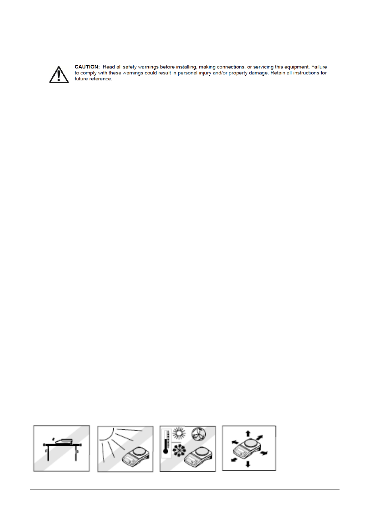
1.3 Safety Precaution
For AC mains powered models:
- Verify that the local AC power supply is within the input voltage range printed on the equipment’s data
label. - Only connect the AC power cord to a compatible grounded electrical outlet.
For AC adapter powered models:
- Verify that the local AC power supply is within the input voltage range printed on the AC adapter’s
data label. - Only connect the AC adapter to a compatible grounded electrical outlet.
Do not position the scale such that it is difficult to disconnect the power cord from the power
receptacle.
This equipment is intended for indoor use and should only be operated in dry locations.
Operate the equipment only under ambient conditions specified in the user instructions.
Do not operate the equipment in hazardous or unstable environments.
Disconnect power from the equipment before cleaning or servicing the equipment.
Service should only be performed by authorized personnel.
Use electrostatic protection measures when handling the printed circuit board.
Only use original replacement parts and accessories.
1.4 Service Facilities
To service a scale Base, the service area should meet the following requirements:
Clean and level environment.
Away from magnetic fields such as motors or large transformers.
Free of vibrations such as fork lift trucks close by, large motors, etc.
Stable and level work surface.
Not exposed to direct sunlight or radiating heat sources.
Ohaus Corporation www.ohaus.com 3 Defender™ Series Bases Service Manual
Page 5

1.5 Tools and Test Equipment Required
Construction
Platform – Stainless Steel
Scale Base – Carbon Steel or Stainless steel
Load Cell – Aluminum
Overloading
Corner Loading –1/2 to 2/3 of Full Capacity
Safe Overload – 150% of Full Capacity
Ultimate Overload – 300% of Full Capacity
Operating Environment
Ambient temperature: -10º C to +40º C
Relative humidity: up to 80% at 31º C, decreasing linearity to 50% at
40º C
Height above sea level: Up to 2,000m
Operability is assured at ambient temperature -10º C to + 40º C
1. Common hand tools
2. Standard electronics tool kit
3. Digital Voltmeter (DVM) capable of reading from 1 mv to 50 V dc.)
4. Megohmeter (50 Volt dc maximum test voltage)
5. Desk magnifier on a stand
6. Ohaus Indicator: Defender 5000, or equivalent commercial indicator
7. A calibrated Torque Wrench N.m. – Ft/Lbs
1.6 Test Masses Required
The masses required to test the Ohaus Defender series Bases when connected to an Indicator must meet the
requirements of ASTM Class or OIML. Mass values 3kg to 600kg, depending on the Base model. The full
scale rated capacity of the Base should be used for Span calibration.
1.7 Service Strategy
The Load Cells used in Ohaus Bases are non-repairable. The repair method for the Base is direct replacement
of Load Cells with connecting cable and hardware.
The Defender series Base contains the following basic replaceable assemblies: Platform, Load Cell with
Connecting Cable, and Down Stop and mounting hardware. There is an exploded view drawing of the Base
and associated parts list in Chapter 5. This service manual contains sufficient information to isolate the
problem, replace the component, test and restore the Base to its original factory specifications.
1.8 Physical Description: Model Defender Series Base
Ohaus Corporation www.ohaus.com 4 Defender™ Series Bases Service Manual
Page 6
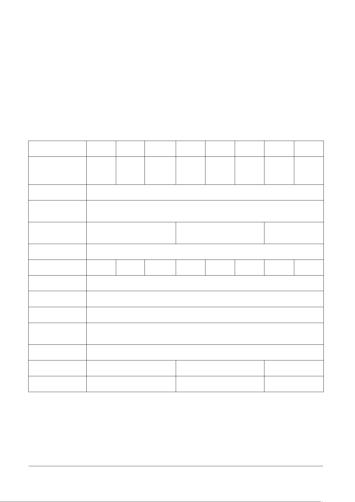
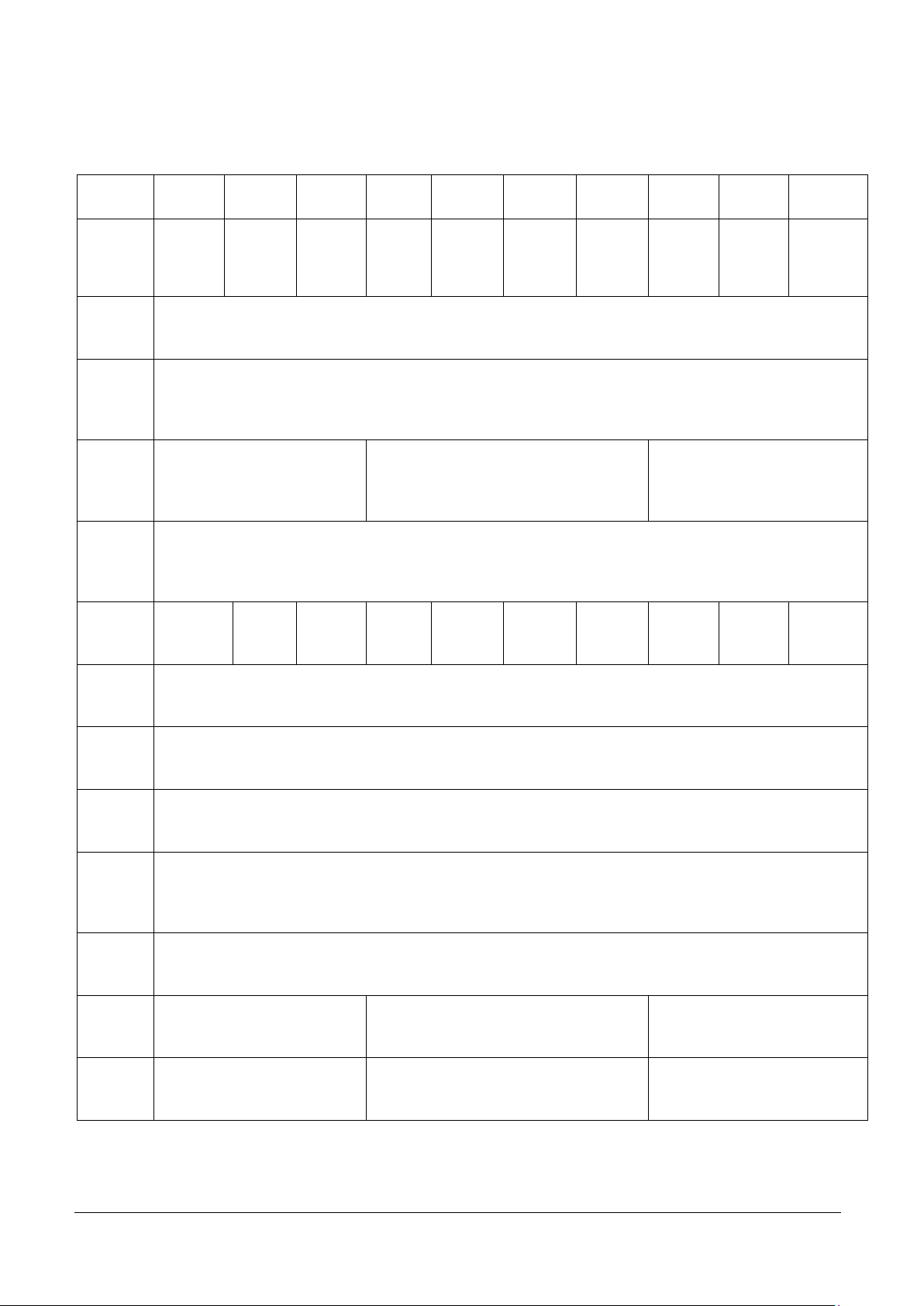
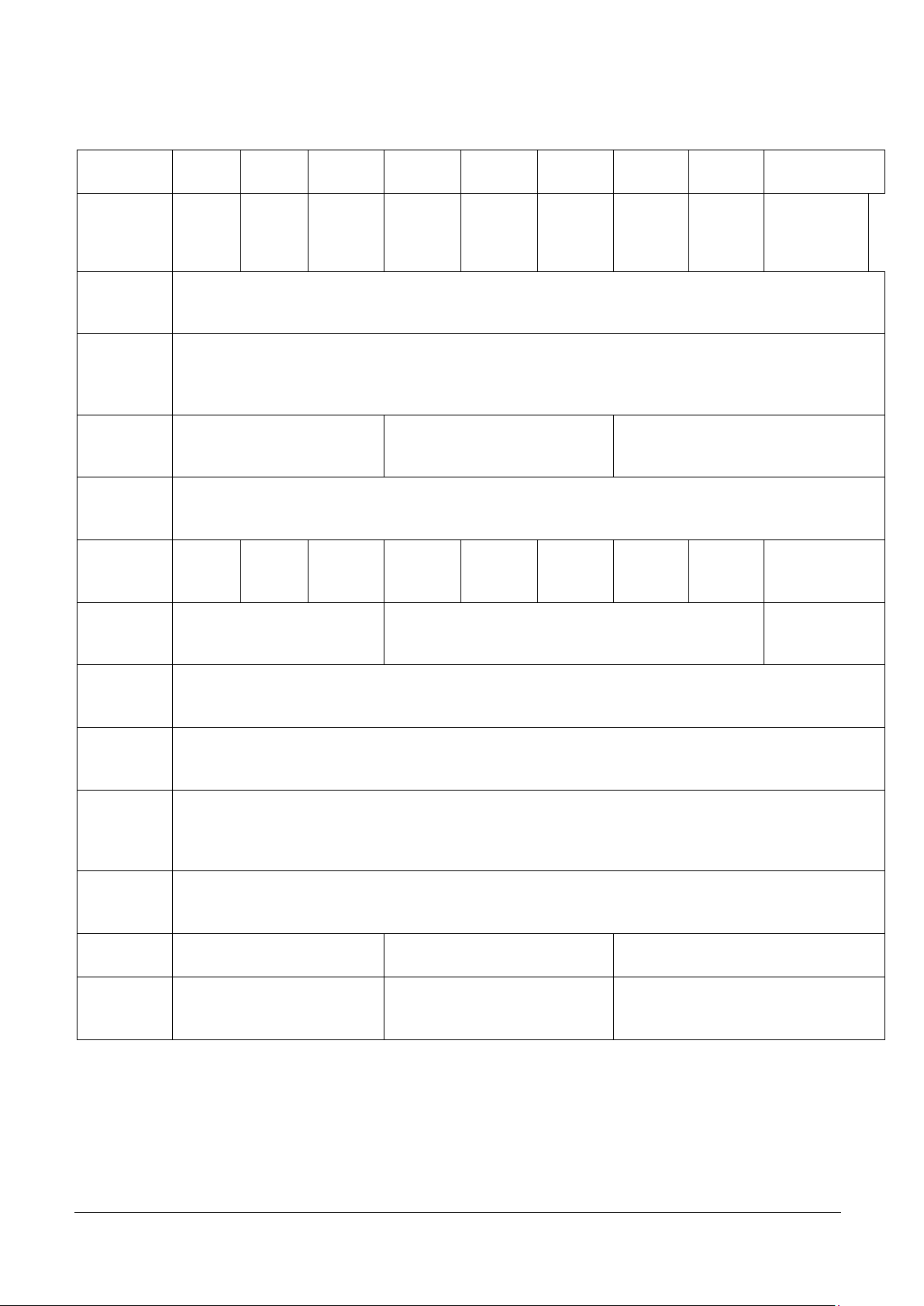
1.9 Specifications
MODEL
D12RQR
D25RQR
D50RQR
D12RTR
D25RTR
D50RTR
D50RQL
D125RQL
Capacity
25 lb /
12.5 kg
50 lb /
25 kg
100 lb /
50 kg
25 lb /
12.5 kg
50 lb /
25 kg
100 lb /
50 kg
100 lb /
50 kg
250 lb /
125 kg
Approved Resolution
NTEP and Measurement Canada 5000e
Safe Overload
Capacity
150% of capacity
Pan Dimensions
305 x 305 mm
12 x 12 in
305 x 355 mm
12 x 14 in
457 x 457 mm
18 x 18 in
Base Construction
Stainless Steel platform with painted steel frame and rubber leveling feet
Load Cell Capacity
22 kg
50 kg
100 kg
22 kg
50 kg
100 kg
100 kg
200 kg
Load Cell Cable
2 m L x 6-wire
Load Cell Type
350 Ohm, aluminum, single point
Load Cell Excitation
5-15V DC/AC
Load Cell Rated
Output
2mV/V
Load Cell Protection
IP67
Net Weight
6.kg / 13.2 lb
7 kg / 15.4 lb
11.5 kg / 25.4 lb
Shipping Weight
7 kg / 15.4 lb
8 kg / 17.6 lb
13.5 kg / 29.8 lb
Complete specifications for the Ohaus Defender series Bases are listed in Table 1-1. When a Base has been
serviced, it must meet the specifications listed in the table. Before servicing the Base, determine what
specifications are not met.
TABLE 1-1. SPECIFICATIONS FOR DEFENDER SERIES BASES
Ohaus Corporation www.ohaus.com 5 Defender™ Series Bases Service Manual
Page 7
MODEL
D50RTX
D125RTX
D250RTX
D50RQV
D125RQV
D250RQV
D500RQV
D125RTV
D250RTV
D500RTV
Capacity
100 lb /
50kg
250 lb /
125 kg
500 lb /
250 kg
100 lb /
50 kg
250 lb /
125 kg
500 lb /
250 kg
1000 lb /
500 kg
250 lb /
125 kg
500 lb /
250 kg
1000 lb /
500 kg
Approved
Resolution
NTEP and Measurement Canada 5000e
Safe
Overload
Capacity
150% of capacity
Pan
Dimension
s
457 x 610 mm
18 x 24 in
610 x 610 mm
24 x 24 in
600 x 800 mm
24 x 31.5 in
Base
Constructi
on
Stainless Steel platform with painted steel frame and rubber leveling feet
Load Cell
Capacity
100 kg
250 kg
500 kg
100 kg
250 kg
500 kg
750 kg
250 kg
500 kg
750 kg
Load Cell
Cable
2 m L x 6-wire
Load Cell
Type
350 Ohm, aluminum, single point
Load Cell
Excitation
5-15V DC/AC
Load Cell
Rated
Output
2mV/V
Load Cell
Protection
IP67
Net
Weight
21.5 kg / 47.4 lb
31 kg / 68.3 lb
39.2 kg / 86.4 lb
Shipping
Weight
24 kg / 52.9 lb
34 kg / 75.0 lb
42.7 kg / 94.1 lb
Ohaus Corporation www.ohaus.com 6 Defender™ Series Bases Service Manual
Page 8
MODEL
D2WQS
D5WQS
D12WQS
D12WQR
D25WQR
D50WQR
D25WQL
D50WQL
D125WQL
Capacity
5 lb /
2.5 kg
10 lb /
5 kg
25 lb /
12.5 kg
25 lb /
12.5 kg
50 lb /
25 kg
100 lb /
50 kg
50 lb /
25 kg
100 lb /
50 kg
250 lb /
125 kg
Approved
Resolution
NTEP and Measurement Canada 5000e
Safe
Overload
Capacity
150% of capacity
Pan
Dimensions
254 x 254 mm
10 x 10 mm
305 x 305 mm
12 x 12 in
457 x 457 mm
18 x 18 in
Base
Construction
Stainless Steel platform with stainless steel frame and rubber leveling feet
Load Cell
Capacity
6 kg
10 kg
30 kg
30 kg
50 kg
100 kg
50 kg
100 kg
200 kg
Load Cell
Cable
1 m L x 4-wire
2 m L x 6-wire
2.5 m L x 6-wire
Load Cell
Type
350 Ohm, stainless steel, single point
Load Cell
Excitation
5-15V DC/AC
Load Cell
Rated
Output
2mV/V
Load Cell
Protection
IP67
Net Weight
4.5 kg / 9.9 lb
6 kg / 13.2 lb
12.5 kg / 27.6 lb
Shipping
Weight
6 kg / 13.2 lb
7 kg / 15.4 lb
14 kg / 30.9 lb
Ohaus Corporation www.ohaus.com 7 Defender™ Series Bases Service Manual
Page 9
MODEL
D50WTX
D125WTX
D250WTX
D50WQV
D125WQV
D250WQV
D500WQV
Capacity
100 lb /
50 kg
250 lb /
125 kg
500 lb /
250 kg
100 lb /
50 kg
250 lb /
125 kg
500 lb /
250 kg
1000 lb /
500 kg
Approved Resolution
NTEP and Measurement Canada 5000e
Safe Overload Capacity
150% of capacity
Pan Dimensions
457 x 610 mm
18 x 24 in
610 x 610 mm
24 x 24 in
Base Construction
Stainless Steel platform with stainless steel frame and rubber leveling feet
Load Cell Capacity
150 kg
300 kg
500 kg
150 kg
300 kg
500 kg
750 kg
Load Cell Cable
2 m L x 6-
wire
2.5 m L x 6-wire
2 m L x 6-
wire
2.5 m L x 6-wire
Load Cell Type
350 Ohm, stainless steel, single point
Load Cell Excitation
5-15V DC/AC
Load Cell Rated Output
2mV/V
Load Cell Protection
IP67
Net Weight
24 kg / 52.9 lb
31.5 kg / 69.4 lb
Shipping Weight
26 kg / 573 lb
35.5 kg / 78.3 lb
Ohaus Corporation www.ohaus.com 8 Defender™ Series Bases Service Manual
Page 10

1.10 How Load Cells Operate
Force
Wheatstone Bridge Circuit
Strain Gauge
+
Strain Gauge
–
Strain Gauge
Strain Gauge
Printed Circuit Board (PCB )
completing Wheatstone
Bridge circuit
Strain Gauges
Internal PCB
Beam
Attachment
points to
Platform
Load Cells convert force into a signal. The Defender Series Bases have a Strain Gauge Load Cell, which is
made from a metal beam with holes drilled in it. Strain gauges are affixed to the beam at the top and bottom to
measure changes in the beam due to deflection. The gauges are bonded very securely to the metal, where
they sense very small deflections in the metal caused by the load being applied to the cell. Because the signal
levels are very small, the circuit is protected from all outside influences such as moisture, physical damage, or
electrical interference.
Figure 1-1. Typical Strain Gauge Load Cell.
The strain gauges are wired into a Wheatstone Bridge Circuit. (See Figure 1-2.)
Figure 1-2. Downward force on the Platform bends the beam, causing two gauges to stretch and
two to compress in opposition, changing the electrical resistance of the circuit.
At zero load, all strain gauges are unstressed. Weight placed on the Platform bends the beam, causing
two gauges to stretch and two to compress in opposition, changing the electrical resistance of the circuit.
The difference in the output signal before and after the mass was placed on the platform is measured,
interpreted and displayed.
Ohaus Corporation www.ohaus.com 9 Defender™ Series Bases Service Manual
Page 11

FUNCTION
WIRE COLOR
+ Excitation
Green
- Excitation
Black
+ Signal
Red
- Signal
White
+ Sense
Blue
- Sense
Brown
Shield
Yellow
Tension
Tension
Compression
Compression
+Excitation
(Supply)
–Excitation
(Supply)
INPUT(volts)
LOADCELL
2 mV/V
Strain
Gauges
4 strain gauges
connected as a
Wheatstone
Bridge
OUTPUT (milli volts)
+Sig
–Sig
Figure 1-3. Route of electrical Load Cell input and output through Wheatstone Bridge circuit.
A Load Cell is a force sensor, which receives a voltage (excitation) from a regulated power source in the
Indicator, and sends back a low-voltage milli-volt (mV) relative to the force applied. The Load Cell signal is
read by the Indicator, which converts it to a numeric value and shows it visually. This output value increases
as weight is loaded to the Load Cell.
For example, a 500kg Load Cell with 2mV/V output and 5V excitation would have a change of 0.02mV per kg
change in the load, that is, 10mV/500=0.02mV per kg. At a load of 250kg the signal voltage would thus
increase by 5mV from the value measured at no load.
1.11 Load Cell Connection
Type1. DxxxWxx Bases
Ohaus Corporation www.ohaus.com 10 Defender™ Series Bases Service Manual
Page 12

Type2. DxxxRxx Bases
FUNCTION
WIRE COLOR
+ Excitation
Green
- Excitation
Black
+ Signal
White
- Signal
Red
+ Sense
Blue
- Sense
Brown
Shield
Yellow
Ohaus Corporation www.ohaus.com 11 Defender™ Series Bases Service Manual
Page 13

CHAPTER 2 TROUBLESHOOTING
2.1 Troubleshooting
This section of the manual provides guidelines for evaluating the condition and performance of a Base unit,
and a standard troubleshooting methodology to follow.
2.1.1 Checking Load Cells for Trouble
Visual Check: Examine the Load Cell for signs of bending, twisting or corrosion.
– Clean the unit before evaluating any mechanical problems. In some cases, debris may have
accumulated inside the Base Housing. Make sure there is no buildup of any foreign material.
– Examine the Base Housing for dents, bent Platform or signs of physical abuse that could
cause the Base to malfunction. Make sure that the proper Platform is supplied with the Base.
Replace all damaged parts. See Chapter 5 for parts list.
– Remove the Platform from the Base. Check that the Overload Stops are not touching the Top
Plate. This would restrict movement, causing improper operation of the Base. If the Overload
Stops are improperly set, adjust them. (See Section 3.3.)
– Check the metal surfaces of the Platform. All surfaces should be parallel.
If the platform is deformed, it should be replaced.
– Check the cables leading to the Load Cell for cuts, abrasions or other signs of excessive wear
and tear.
– Check for a bent or twisted Load Cell: Place the top surface and then each of the sides of the
Load Cell on a flat surface, to see if it rests flat and even. A gap indicates a bent or twisted
Load Cell.
– Examine the Load Cell for corrosion due to high humidity or exposure to chemicals.
– A Load Cell that is even slightly bent or corroded should be replaced.
Perform a Resistance Test, to determine if the Load Cell is severely damaged or a short
circuit to the frame has occurred. (See Chapter 4 for details.)
Perform an Output Voltage Test: Measure the no load, 50% load and full load output.
The reading should meet the Load Cell specifications. (See Chapter 4.)
– The Load Cell output should be very close to linear over its capacity range.
Ohaus Corporation www.ohaus.com 12 Defender™ Series Bases Service Manual
Page 14

CHAPTER 3 MAINTENANCE AND REPAIR PROCEDURES
3.1 Preventive Maintenance
Ohaus bases should be carefully handled, stored in a clean, dry area, and cleaned periodically. Follow these
precautionary steps:
– When a base has had chemicals or liquids spilled on it, all exterior surfaces should be
cleaned as soon as possible with warm water on a damp cloth.
– Do not leave a mass on the base when it is not in use.
– Allow time for the base to stabilize after moving it from an area which is at a different
temperature than the area where it is to be operated. Allow one hour for each 5°F (2.7°C)
temperature change before using the base.
3.1.1 Preventive Maintenance Checklist
The scale should be inspected and checked regularly, as follows:
1. Clean the base.
2. Remove the Platform to inspect and clean the area beneath the Platform.
CAUTION
DO NOT USE CHEMICAL CLEANERS OR SOLVENTS OF ANY TYPE.
SOME CLEANERS ARE ABRASIVE AND MAY AFFECT THE BASE’S FINISH.
3. Check the Load Cell cable for broken or damaged insulation.
4. Make a visual inspection as detailed in Chapter 2.
3.2 Replacing the Load Cell
A Load Cell that is even slightly bent or corroded should be replaced. The Load Cell may also need to be
replaced because of instability, or because the scale does not calibrate or repeat, or because it is physically
broken.
1. Remove the scale Platform and disconnect the Base from the Indicator.
2. Remove the Load Cell Mounting Bolts and washers that secure the Top Frame to the Load
Cell.
3. Set the Top Frame and the Load Cell Spacer aside.
4. Remove the bottom Load Cell Mounting Bolts, washers and spacer. The Load Cell assembly
can now be removed from the Lower Frame.
5. Install the new Load Cell following steps 1 through 4 in reverse order.
Ohaus Corporation www.ohaus.com 13 Defender™ Series Bases Service Manual
Page 15

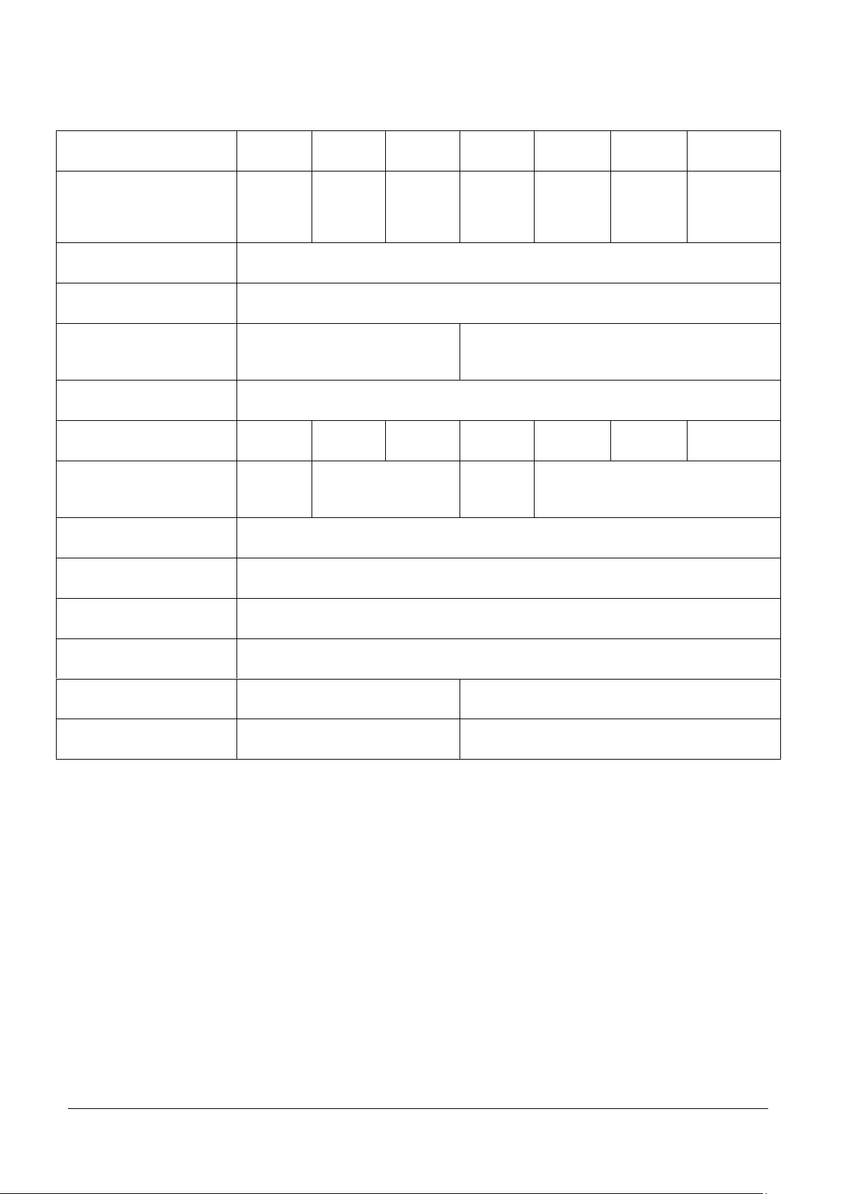
3.3 Overload Stop Adjustment
Base Model
Pan size
Overload Stop
Center (mm)
Overload
Stop Corner
(mm)
Shipping
Spacer
D2WQS
254 x 254
10" x 10"
0.8 2 Y
D5WQS
1.5 2 Y
D12WQS
2.5
3.5
Y
D6RQDR
305 x 305
12'' x 12''
0.8 1 N
D12RQR
1 1 N
D15RQDR
1.2
1.5 N D25RQR
1 2 Y
D30RQR
1.5 2 Y
D50RQR
2.5
3.5 Y D6WQDR
1
1.5 N D12WQR
0.8
1.5 N D15WQDR
0.6
2.5
Y
D15WQR
0.6
2.5 Y D25WQR
0.8 2 Y
D30WQR
1 2 Y
D50WQR
1
3.5
Y
D12RTR
305 x 355
12'' x 14'
1
1.5
N
D25RTR
1.5 2 Y
D60RTR
2.5
3.5 Y D50RTR
2.5
3.5
N
The Overload Stop gaps must be checked and reset if the Load Cell is replaced.
Figure 3-1. Overload Stops on Defender series Base
1. Remove the Platform and loosen the Jam Nuts.
2. Use the appropriate size feeler gauge in the Gap (see Table 3-1), and turn the screws until a
slight drag is felt on the feeler gauge.
3. Tighten the Jam Nut and re-check the Gap.
4. Re-adjust if necessary.
5. Cover the Platform and check for full capacity. (See Table 3-1 for Gap settings.)
TABLE 3-1. OVERLOAD GAP SETTINGS FOR DEFENDER SERIES BASES
Ohaus Corporation www.ohaus.com 14 Defender™ Series Bases Service Manual
Page 16

D15RTDR
1.2
1.5 N D30RTDR
1.5 2 N
D15RQDL
400 x 400
15.7" x 15.7"
1.5
2.5
Y
D30RQDL
1.5
3.5 Y D60RQDL
2 5 Y
D15WQDL
0.6
3.5 Y D15WQL
0.6
3.5 Y D30WQDL
0.8
3.5 Y D30WQL
0.8
3.5 Y D60WQDL
2 6 Y
D60WQL
0.9 6 Y
D50RQL
457 x 457
18" x 18"
1
3.5 Y D125RQL
2 6 Y
D25WQL
1 2 Y
D50WQL
1
3.5 Y D125WQL
1.5 6 Y
D60RTDL
400 x 500
15.7" x 19.6"
1
1.5
N
D150RTDL
1.5
2.5 Y D60WTDL
1
3.5 Y D150WTDL
1.5 6 Y
D60RTL
1
1.5 N D150RTL
1.5
2.5 Y D60WTL
1
3.5 Y D150WTL
1.5 6 Y
D50RTX
457 x 610
18" x 24"
0.8
1.5 N D125RTX
1.2
2.5
Y
D250RTX
1.5
3.5
Y
D50WTX
0.8
3.5 Y D125WTX
1 6 Y
D250WTX
1.5 9 N
D60RQDX
500 x500
19.6" x 19.6"
1 2 Y
D150RQDX
0.9 5 Y
D60WQDX
0.6 5 Y
D60WQX
0.8 5 Y
D150WQDX
0.8 6 Y
D150WQX
0.9 6 Y
D50RQV
610 x 610
24" x 24"
0.8
1.5
N
D60RQDV
0.6
1.5 N D125RQV
1
2.5 Y D150RQDV
1
3.5 Y D250RQV
1.2
3.5 N D300RQDV
1.4 5 N
D500RQV
1.8 6 N
D60WQDV
0.8 2 Y
D60WQV
0.5 2 Y
D150WQDV
0.7 5 Y
D150WQV
0.6 5 Y
D300WQDV
1 7 N
D50WQV
0.8 2 Y
D125WQV
1 5 Y
D250WQV
1.2 6 N
D500WQV
1.5
12
N
Ohaus Corporation www.ohaus.com 15 Defender™ Series Bases Service Manual
Page 17

D125RTV
600 x 800
23.6" x 31.5"
1.2
3.5
N
D150RTDV
0.9
3.5
N
D250RTV
1.8 5 N
D300RTDV
1.2 6 N
D500RTV
2.2 9 N
D600RTDV
2.2 8 N
D150WTDV
1 6 Y
D300WTDV
1.2 9 N
D600WTDV
1.5
12
N
Ohaus Corporation www.ohaus.com 16 Defender™ Series Bases Service Manual
Page 18

CHAPTER 4 TESTING
Models
Ex+ to Ex–
S+ to S–
Ex+ to S–
Ex+ to S+
Ex– to S+
Ex– to S–
All Defender series
Bases
410 ± 15
350 ± 5
322.5 ± 15
322.5 ± 15
262.5 ± 15
262.5 ± 15
4.1 Testing
Before and after servicing a Defender series Base, conduct Load Cell Resistance Checks, Calibration using an
external Indicator, and Performance Tests to confirm that the base meets specifications. Allow time for the
base to stabilize after moving it from an area which is at a different temperature than the area where it is to be
operated. Allow one hour for each 5°F (2.7°C) temperature change before using the base.
The following tests require a Digital Multimeter, an Indicator and hand tools. The Digital DC Voltmeter should
have a reading range from 1 mV to 50 V full-scale. It should be capable of reading differences of one microvolt per increment. The indicator can be either the Ohaus
Defender 3000 series, or an equivalent commercial indicator.
ARTTENTION: Make sure the test area is free from drafts and that the base rests on a level
and vibration-free surface.
4.2 Load Cell Resistance Checks
Use an ohm-meter to measure across each pair of wires in turn, and compare the results with Table 4-1. The
Load Cell must be completely disconnected from the Indicator and at no load when these tests are made.
In addition to the four resistance elements which make up the Wheatstone Bridge, there are commonly one or
two resistors in the excitation lines. The resistance across the excitation wires is usually the highest resistance
measured across any two wires.
If the resistance readings are in the range specified, skip to the next section. If they are incorrect – for
example, outside the expected range, open circuit or short-circuit across any two wires – the likely causes are
a damaged or faulty Load Cell or incorrect or faulty wiring. If the Load Cell is defective, replace it. (See
Chapter 3.)
TABLE 4-1. LOAD CELL RESISTANCE READINGS (in Ohms)
4.3 Calibration with an External Indicator
1. Install the Load Cell in position. (See Section 3.2.)
2. Connect the excitation, signal shield and sensing wires (if provided), to the Indicator.
Calibrate the Indicator to read the load in the units required, for example, kilograms or
grams. (Consult the Indicator instruction manual for calibration procedures.) For
calibration mass weights, see Table 1-1, in Chapter 1.
3. Check that the Indicator is reading correctly over a range of values.
Ohaus Corporation www.ohaus.com 17 Defender™ Series Bases Service Manual
Page 19

4.4 Consistency Check
TABLE 4-2. LOAD CELL OUTPUT READINGS
(in mV with 5V Excitation)
Zero Load
50% Load
100% Load
±0.1mv
4-6mv
9-11mv
To check the system prior to installation, make the following measurements. (Also make these checks if the
Indicator will not calibrate, or if the Indicator does not read correctly, or is giving unstable readings.)
1. Using a voltmeter, measure and record the excitation voltage supplied by the Indicator. Most
Ohaus indicators supply 5 volts dc for the excitation voltage.
2. Using an mV meter, measure and record the signal voltage with no load on the base.
CAUTION:
IN THE NEXT STEP, DO NOT OVERLOAD THE BASE BEYOND FULL CAPACITY RATING.
3. Using an mV meter, measure and record the signal voltage.
4. Obtain the mV/V output figure from the Load Cell data supplied with the Load Cell, and
compare the signal changes seen with the theoretical values from the Load Cell data. (See
Table 4-2.)
4.5 Performance Tests
Accurate performance of the Defender series Bases is determined by two performance tests. The displayed
readings are compared with the tolerances listed in Table 1-1.
NOTE:
The following performance tests are used to evaluate base operation before and after repairs.
The base must meet the requirements specified in each test as well as the specifications listed
in Table 1-2. Before proceeding with the following tests, the base should be attached to an
indicator and calibrated.
(See Section 4.3.)
Ohaus Corporation www.ohaus.com 18 Defender™ Series Bases Service Manual
Page 20

4.5.1 Off Center Load (Shift) Test
A
B
C
D
The Off Center Load (Shift) Test is made before and after a Base has had the Load Cell replaced and
adjustments have been made that affect its performance. The Off Center Load Test verifies that all sections of
the Base weigh within specified tolerance.
If the Base does not pass the Off Center Load Test, verify that the Overload Stops are properly set. (See
Section 3.1.)
If the Off Center Load Test cannot be passed, the Load Cell must be adjusted or replaced.
Prior to starting this test, the Base must be connected to a properly functioning Indicator, with capacity and
readability values set according to the specifications for the Base under test.
5. Place test weights equal to one third of the Base's capacity sequentially at each of the
positions A, B, C, and D, as shown in Figure 4-1. Note the Indicator reading at each
position. (For Base capacity, see Table 1-1.)
6. Check the variation between mass weights and indicator reading against specified Shift
Tolerance in Table 1-1.
Figure 4-1. Positions A, B, C and D are centered
at each quarter of the base platform.
Ohaus Corporation www.ohaus.com 19 Defender™ Series Bases Service Manual
Page 21

4.5.2 Adjusting Off Center Load
Top view of Load Cell
Side view of Load Cell
1
2
3
4
If the Off Center Load (Shift) is excessive, perform adjustment as follows:
Figure 4-2. Off Center Load adjustment points.
1. Place the test weight in the center of the Platform.
2. Tare the indicator.
3. Move the weight to point A and record the reading.
4. Move the weight to point B and record the reading.
5. Move the weight to point C and record the reading.
6. Move the weight to point D and record the reading.
7. If the reading at point A is negative, file at points 1 and 4 AT AN ANGLE.
8. If the reading at point B is negative, file at points 1 and 2 STRAIGHT ACROSS.
9. If the reading at point C is negative, file at points 2 and 3 AT AN ANGLE.
10. If the reading at point D is negative, file at points 3 and 4 STRAIGHT ACROSS.
Note: It is not recommended that you try to adjust more than –5 counts if the beam has been filed
already. If the beam has not been filed previously, you can adjust –10 counts. Remember, when filing
you are weakening the beam. File a little at a time.
Ohaus Corporation www.ohaus.com 20 Defender™ Series Bases Service Manual
Page 22

4.5.3 Full Load Test
1. After the Off Center Load Test has been passed, test the Base’s full capacity according to
the Specification Table 1-1. The Base must meet all specifications as listed.
2. If the Base fails the Full Load Test, check and set the Down Stops.
(See Section 3.3.)
This section of the manual contains exploded views for the Defender E Bases. The exploded view drawings
are designed to identify the parts which can be serviced in the field.
ATTENTION: In all cases where a part is replaced, the base must be thoroughly checked after
the replacement is made. The base MUST meet the parameters of all applicable
specifications in this manual.
If further technical information is needed, please contact your local Ohaus office, or:
Ohaus Corporation
7 Campus Drive, Suite 310
Parsippany, NL 07054, USA
Tel: +1 973-377-9000
Fax: +1 973-944-7177
In the United States call toll free, 800-672-7722 ext. 7852 between 8:00 a.m. and 5:00 p.m. EST.
Ohaus Corporation www.ohaus.com 21 Defender™ Series Bases Service Manual
Page 23

CHAPTER 5 PARTS IDENTOFICATION
5.1 Defender series Base: Carbon Steel model
Figure 5-1. Defender series Base: D52 RQR
Ohaus Corporation www.ohaus.com 22 Defender™ Series Bases Service Manual
Page 24

Drawing
Item
Part Number
Description
Remarks
1
30427798
Pan, 305x305, SST, D52
2 30427800
Rubber Support, CS Base, D52
3 71125009
Foot CHII
4
30427806
Hardware Kit, R Base, D52
5 30427876
Load Cell 0785-22kg 2m
For D12RQR
30427877
Load Cell 0785-50kg 2m C3.5
For D25RQR
30448396
Load Cell 0785-50kg 2m C3MI
For D30RQR
30427878
Load Cell 0785-100kg 2m C3
For D50RQR
30448394
Load Cell 0785-11kg 2m C3MI
For D6RQDR,
D6RQR
30448395
Load Cell 0785-22kg 2m C3MI
For D15RQDR,
D15RQR
NS
30424416
Box, R, D52
NS
30448403
Box Complete, R, Big, D52
Ohaus Corporation www.ohaus.com 23 Defender™ Series Bases Service Manual
Page 25

5.2 Defender series Base: Stainless Steel model
Figure 5-2. Defender series Base: D52 WQR
Ohaus Corporation www.ohaus.com 24 Defender™ Series Bases Service Manual
Page 26

Drawing Item
Part Number
Description
Remarks
1
30427798
Pan, 305x305, SST, D52
2
30427801
Rubber Support, SST Base,
D52
3
30448404
Foot Set, SST S base, D52
4 30427806
Hardware Kit, R Base, D52
5
30448394
Load Cell 0785-11kg 2m C3MI
For D6WQDR,
D6WQR
30448395
Load Cell 0785-22kg 2m C3MI
For D15WQDR
30448396
Load Cell 0785-50kg 2m C3MI
For D30WQDR,
D30WQR
30448267
Load Cell SLP532-30kg C3
2m
For D15WQR,
D12WQR
30448388
Load Cell SLP532-50kg C3
2m
For D25WQR
30448389
Load Cell SLP532-100kg C3
2m
For D50WQR
NS
30424416
Box, R, D52
NS
30448403
Box Complete, R, Big, D52
NOTE:
When replacement parts are needed, refer to the spare part list for the model you are servicing. Parts lists are
available from your local Ohaus office. To locate your nearest office, visit www.Ohaus.com.
Ohaus Corporation www.ohaus.com 25 Defender™ Series Bases Service Manual
Page 27

APPENDIX A. GLOSSARY
Ohaus Load Cells contain a specification label on the Load Cell itself.
Compensated Temperature Range
The range of temperatures over which the output from the cell is compensated. If used outside this
range the output cannot be guaranteed to follow the specifications.
Environmental Protection
IP rating against moisture and dust, for example, IP 65.
Excitation
Voltage applied to the Exe+ and Exe– leads of the load cell.
Input Resistance
The resistance measured across Exe+ and Exe– with load cell disconnected and
no load.
Insulation Resistance
Normally measured at 50 V dc, this is the minimal resistance between the metal body of the load cell
and any of its electrical connections.
Mechanical Failure
The load at which the cell is likely to fail mechanically, that is, break or deform.
mV/V
Usually the output from a load cell will be approximately 0m V at zero load, though typically there may
be a small offset voltage at zero load. Over the full rated capacity of the load cell, the mV output will
change. The amount by which it changes depends upon the resistance change in the cell and on the
excitation voltage applied. Since the load cell manufacturer does not know what excitation voltage will
be applied to the cell, rather than quote the V output over full range, they will quote the milli-Volt output
per volt of excitation, or in its short form, mv/V. Most Ohaus Indicators provide an excitation voltage of
5 Volts dc.
Output Resistance
The resistance measured across S+ plus and S– with load cell disconnected and
no load.
Overload Capacity
The maximum load that can be applied without permanent damage. Loads in excess of maximum
capacity will cause damage to the load cell.
Rated Capacity
The maximum load over which the load cell will operate within its specifications.
Rated Output
The nominal mV/V output of the load cell.
Ultimate Capacity
This is a percentage setting, usually 300% of full capacity.
Zero Balance
The output of the load cell at no load, normally quoted as a percentage of full load. Also known as
zero offset.
Ohaus Corporation www.ohaus.com 26 Defender™ Series Bases Service Manual
Page 28

OHAUS Corporation
7 Campus Drive
Suite 310
Parsippany, NJ 07054 USA
Tel: +1 973 377 9000
Fax: +1 973 944 7177
With offices worldwide
www.ohaus.com
*30479276A*
P/N 30479276A © 2018 OHAUS Corporation, all rights reserved
 Loading...