

Page 1

MODEL
OHAUS CORPORATION
D500M
PORT ABLE BEAM SCALE
ASSEMBL Y MANUAL AND
OPERATING INSTRUCTIONS
Page 2

MODEL D500M PORTABLE BEAM SCALE ASSEMBLY MANUAL AND OPERATING INSTRUCTIONS
2
Page 3
OHAUS CORPORATION
INDEX
I. DESCRIPTION........................................................................................................................................................................04
II. SPECIFICATIONS.................................................................................................................................................................. 04
III. ASSEMBLY/INSTALLATION................................................................................................................................................ 06
IV . SHIFT....................................................................................................................................................................................... 08
V. ZERO ADJUSTMENT............................................................................................................................................................ 09
VI. OPERATING INSTRUCTIONS............................................................................................................................................ 09
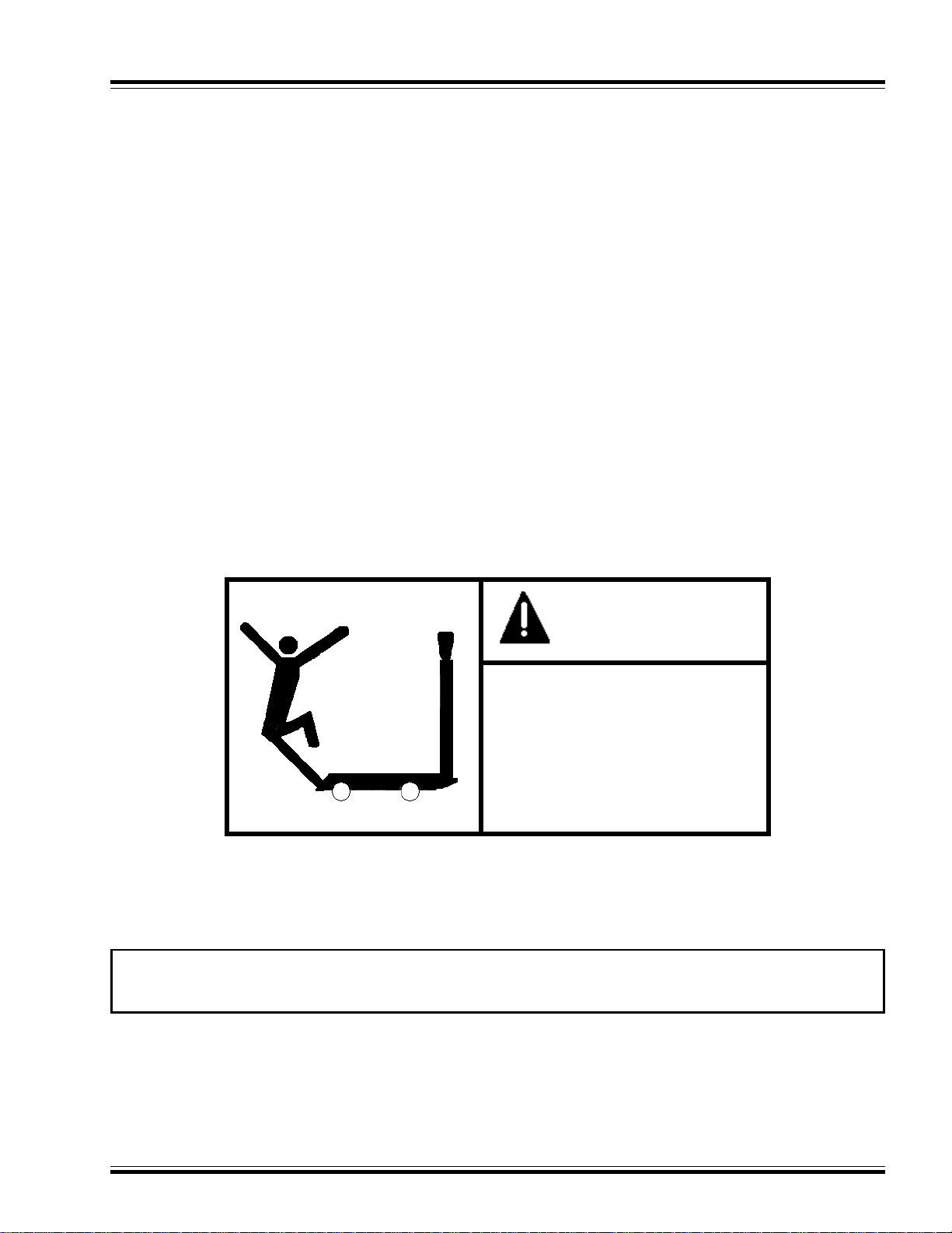
CAUTION
PLACE WEDGES
UNDER WHEELS
BEFORE USING
SCALE
OHAUS CORPORATION RESERVES THE RIGHT TO MAKE REFINEMENTS OR
CHANGES WITHOUT NOTICE
3
Page 4
MODEL D500M PORTABLE BEAM SCALE ASSEMBLY MANUAL AND OPERATING INSTRUCTIONS
I. DESCRIPTION
The OHAUS D500M is as compact industrial scale designed to meet a variety of weighing needs where simplicity and low cost
are a must.
The D500M features an easy to read flat beam with a shadow-proof poise providing quick reading under all lighting conditions.
A positive beam lock secures the indicator when the scale is not in use.
This scale utilizes a rugged fabricated steel design and is equipped with phenolic wheels for easy portability. A stainless steel
platform is available to tailor the scale to a specific application.
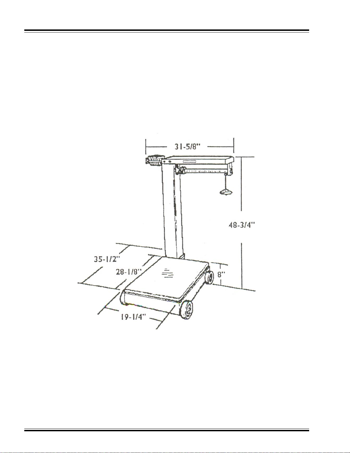
II. SPECIFICATIONS
Figure 1
Available Counterpoise Weights Total
Beams (Included) Capacity
100 lb x 8 oz 2 of 100 lb
1 of 200lb 1000 lb
1 of 500lb
Or
50 kg x 200g 1 of 50 kg
2 of 100 kg 500 kg
1 of 200 kg
Combination beam: avoirdupois (front) and metric (back); includes both sets of counterpoise weights as listed above.
4
Page 5

OHAUS CORPORATION
A - Scale Platform
B - Spider Assembly
C - Beam Assembly
D - Column
E - Beam Shelf
F - Scale Base
G - Load Box Assembly
H - Level Bubble
I - Screw, 1/2-13 x 3 1/4
J - Flat Washer
K - Wheel
L - Hook’s Nose
M - Nut, 3/8-16
N - Lockwasher, 3/8
O - Screw # 10-32 x 3/8
P - Nut, 1/2-13
Figure 2
Q -Counterpoiser´s
R - Lever Assy - Long
S - Rod, Steelyard
T - Screw 1/4 - 20 x 1 1/4"
U - Nut, 1/4 - 20
V - Long Set the Hook
X - Loop Assy - Center
Y - Lever Assy - Short
Z - Short Hook
A1 - Washer
A2 - Screw
5
Page 6

MODEL D500M PORTABLE BEAM SCALE ASSEMBLY MANUAL AND OPERATING INSTRUCTIONS
III. ASSEMBLY / INSTALLATION
(NOTE: Refer to the exploded view diagram, Figure 2, for assembly assistance).
A. Each D500M carton contains five individually packed items. These items are:
1. One scale base.
2. One fog white column, consisting of one foursided column piece, and one steelyard rod.
3. One charcoal black beam shelf.
4. One silver-colored gratuated beam assembly. It is packed inside of the white fog column (item2).
5. One box of loose parts containing (in order of assembly):
a. four wheels.
b. four 1/2" axle bolts, each with one 3/8" nut and two washers, for the wheels.
c. two lock washers and two 3/8" nuts, to tighten the column to the colum support plate.
d. one hook, to be hung on the steelyard rod.
e. four 1/4" hex head screws and four flat washers, to tighten the beam shelf to the column.
f. one triangular load box assembly.
g. one set of counterpoise weights as described in Section II of this manual (two sets of weights, on combination lb/kg
versions).
h. two screw # 10-32 x 3/8.
B. for easy assembly the following tools are recommended:
a. 3/4" socket and ratchet
b. 3/4" open end wrench
c. 7/8" open end wrench
d. 9/16" open end wrench
e. 9/16" deep socket and ratchet
f. 1/4" slotted screwdriver
g. 7/16" socket, box, or open end wrench
C. Following the steps below, assemble your D500M:
1. Remove the plastic wrapping from the scale base.
2. Remove the scale platform from the scale base and set it aside.
3. For reinstallation purppose, note the location of the level bubble (item H, figure 2) on the spider assembly. Also note
the position of the two bolts in the center front and center back of the spider assembly. Lift out the spider assembly
and place it off to the side
4. Remove any cardboard packing and bag of silica gel from inside the scale base.
5. Install each wheel in the following sequence:
a. Slide one flat washer onto the 1/2" axle bolt and slide the bolt through the black phenolic wheel.
b. Slide another flat washer onto the bolt.
c. Lifting the scale base the required distance (appoximately 2-1/2"), insert the bolt through the hole in the scale base
from the outside and screw the bolt through the nut that is welded to the inside of the scale base. Allow sufficient
clearance for the wheel to tum freely.
d. From the inside of the scale base, add the nut onto the bolt.
e. Repeat these steps for the remaining three wheels.
f. Tighten all bolts and nuts for the wheel at this time.
6. Remove the packing around fog white column. Remove also the steelyard rod and the beam assembly from the inside
of the column. Place the column piece onto the column support plate. Ohaus Label on the column must be facing
the scale platform. From underneath the column support plate, install a lock washer and 3/8" nut onto the column roads
and tighten.
Column Rod
Holes For Column Rods
Figure 3
Column
Support
Plate
Figure 4
Column Rod
Lock Washer
Nut 9/16"
6
Page 7

OHAUS CORPORATION
7. Remove the plastic bubble from the beam shelf and beam assembly. Place the beam shelf upside down on the scale
platform. NOTE: Place some type of protection (i.e. carboard) on the scale platform to protect the platform and the beam
shelf from getting scratched.
8. Turn the beam assembly upside down and insert the rounded tip of the beam through the trig opening end of the beam
shelf assembly. To attach the beam assembly to the beam shelf, align the two holes in the plate of the beam assembly
with the two holes in welded plate, install and tighten the two screws # 10-32 x 3/8" (See Figure 5).
Welded Plate
# 10-32 x 3/8" screw
# 10-32 x 3/8" screw
Zero Adjustment Screw
9. Place the hook onto the bottom end of the steelyard rod (refer to the exploded view diagram, Figure 2, for proper
positioning). Lift the assembled beam, turn it over, and attach the top of the steelyard rod through the stirrup on
the beam assembly.
10. Place the assembled beam with the steelyard rod over the column and tighten the column and the assembled beam
by inserting the hex head screws on both sides of the column. These screws should be finger-tightened only.
Beam Shelf
Beam
Assembly
Figure 5
11. From underneath the column support plate, connect the hook that is on the steelyard rod under the pivot at the end
of the main lever of the scale base. Raising the tip of the main lever and some slight twisting of the hook by hand may
be required to get the hook under the pivot.
12. Be sure that the beam shelf is correctly leveled, and tighten the hex head screws (installed in step 10) firmly so as not
to allow any movement. NOTE: BE ALSO SURE THAT THE ROUNDED BEAM TIP IS CENTERED IN THE TRIG
OPENING (FRONT TO BACK) BEFORE TIGHTENING.
13. On the scale base, be sure that the four gold-colored fulcrum assemblies on the lever system are properly hooked
in the slot on the base flange.
14. Reinstall the spider assembly that was removed in step 3. Tilt the front end of the spider assembly, closest to the
column, downward slightly, for ease of reinstallation. The L-shaped bracket located in the center-front on the spider
assembly must be under the base flange; the heads of the two hex head bolts located in the center-front and center
back of the spider must both be inside of the base flange. Once installed, be sure that the four bearings are
properly seated on the four pivots of the main lever system.
15. Reinstall the scale platform removed in step 2.
16. Hook the load box assembly onto the stirrup located at the rounded end of the beam assembly, just inside of the trig
opening.
17. Adjust the scale to zero, if necessary. See Section V of this manual.
18. Place the counterpoise weights in the rack.
7
Page 8

MODEL D500M PORTABLE BEAM SCALE ASSEMBLY MANUAL AND OPERATING INSTRUCTIONS
IV. SHIFT (as needed)
A. TEST
Place a half capacity test load in the center of each quarter of the platform, or use a quarter capacity test load over each
load pivot successively.
If a correction is not needed, proceed to the operating instructions. In a mechanical base, shift refers to the pivot distances
of the levers. If, on a lever, the distances are equal, then a lever is said to have no shift error. Also, two levers which have
the same ratio will have no shift error.
B. ADJUST
The lever illustration of the D500M designates the pivots as follows:
F - Fulcrum Pivot
L - Load Pivot
P - Power Pivot
C - Center Connection
8
Page 9

OHAUS CORPORATION
The rule is to lengthen the distance between the fulcrum and the load pivots to increase the indication. Conversely, shorten
the distance between the fulcrum and the load pivots to decrease the indication. Use hone part number 085061020 (fine) and
part number 085062020 (coarse) to adjust the pivots.
TO LENGTHEN
THE DISTANCE
Note the direction of honing. Always hone away from the load edge of the pivot.
1. Side to Side
To correct a shift error side on a lever, note the indication at each location, and hone the load pivot as needed to correct
the side to side error on either lever. Hone only the load pivots to correct an error on either lever for a side to side correction.
2. Front to Back
When the indications on each load point of each lever are equal side to side and the indications of the levers are different
front to back, then hone the power pivot of the short lever until the two levers are equal front to back. Do not hone the
power pivot of the long lever. Increase the pivot distance from the power pivot to the fulcrum pivot on the short lever
if the short lever has a higher indication than the log lever.
When the Shift error is corrected, recalibrate the scale and retest the shift. Continue calibration and shift test/adjustment
until no shift error is found after the scale is calibrated.
TO SHORTEN
THE DISTANCE
V. ZERO ADJUSTMENT (as needed)
Check the zero balance by positioning the beam poise at "0" on the beam. Turn the locking lever to free the beam. The
beam should float without touching the top bottom of the trig opening. If it touched the top, turn the zero adjustment screw
(Figure 4) counter-clockwise with a screwdriver. Turn the screw clockwise until it is touching the bottom.
VI. OPERATING INSTRUCTIONS
A. SCALE OPERATION
The OHAUS D500M beam utilizes a balancing beam principle to indicate weight. With the scale loaded, slide the
beam poise toward the trig loop (away from the column). Adjust the beam poise until the tip of the beam is in a balance
state within the trig loop. The position of the beam poise indication (red pointer) on the beam will indicate the amount
of weight on the scale platform.
NOTE: When operating the scale, use wedges at the two wheels to prevent the scale from moving.
9
Page 10

MODEL D500M PORTABLE BEAM SCALE ASSEMBLY MANUAL AND OPERATING INSTRUCTIONS
B. INCREASING SCALE CAPACITY
The beam on the D500M provides weight indication up to 100 lb (50 kilograms) and is graduated by 8 ounces (200 grams).
The beam will counter balance a maximum load of 100 lb ( or 50 kilograms). To increase the capacity of the scale, simply
place one or more of the additional counterpoise weights on the load box assembly. (For example, the avoirdupois
D500M includes counterpoise weights, which are (2) 100 lb, (1) 200 lb, and (1) 500 lb). The additional counterpoise
weights are stored in a rack attached to the column cap. Each weight is "notched" to fit the load box assembly.
Counterpoise weights may be used separately or in combination. When using one more of the additional counterpoise
weightsto determine weight on the platform, adjust the beam poise until a balance state is achieved. The weight on the
platform can be determined by adding the sum of the additional counterpoise weights on the load box assembly to the
amount indicated on the beam.
Example: both additional 100 lb counterpoise weights are secured to the load box assembly. The beam poise is indicating
"45 lb", and beam is balance in the trig loop; weight on the scale platform totals 245 lb.
C. FILLING OPERATIONS
When filling containers on the scale, adjust the beam poise to the desired target weight. Add additional counterpoise
weights to the load box assembly if necessary.
A set screw is provided on the bottom of the beam poise to secure to the beam. To inhibit the beam poise from traveling
on the beam (and changing the target weight), It is advisable to tighten the set screw. Fill container until the beam exhibits
a balance condition indicating that the target weight has been achieved.
D. TRIG LOCKING MECHANISM
When moving the scale, it is recommended that the beam be locked in place to prevent damage. A locking mechanism
is provided on the trig loop to inhibit vertical travel of the beam whenever the base is moved. The trig loop locking device
must be disengaged when the scale is in use.
10
Page 11

OHAUS CORPORATION
11
Page 12

MODEL D500M PORTABLE BEAM SCALE ASSEMBLY MANUAL AND OPERATING INSTRUCTIONS
For information in
U.S and Canada, contact:
OHAUS Corporation
19A Chapin Road, P.O. Box 2033
Pine Brook, NJ 07058-2033, USA
Phone: +1-973-377-9000
Fax: +1-973-944-7177
www.ohaus.com
For information in other countries, contact the manufaturer:
TOLEDO DO BRASIL
INDÚSTRIA DE BALANÇAS LTDA.
R. Manoel Cremonesi, 1
Tel. 55 (11) 4356-9000
CEP 09851-330 - Jardim Belita - São Bernardo do Campo - SP - Brasil
site: www.toledobrasil.com.br
e-mail: exp@toledobrasil.com.br
P/N 80252764 © OHAUS Corporation 2008, all rights reserved
*80252764*
Printed in Brazil
3474278
RE: 00-10-08
 Loading...