

Page 1

3000 Series Indicators
Instruction Manual
T31P Indicator
T31XW Indicator
Find Quality Products Online at: [email protected]
www.GlobalTestSupply.com
Page 2

Defender™ 3000 Series Base
Instruction Manual
Find Quality Products Online at: [email protected]
www.GlobalTestSupply.com
Page 3

Compliance
This product conforms to the EMC directive 89/336/EEC and the Low Voltage Directive 73/23/EEC. The
complete declaration of Conformity is available from Ohaus Corporation
Disposal
I
n conformance with the European Directive 2002/96 EC on Waste Electrical and Electronic Equipment
(WEEE) this device may not be disposed of in domestic waste. This also applies to countries outside the
EU, per their specific requirements.
Please dispose of this product in accordance with local regulations at the collecting point specified for
electrical and electronic equipment.
If you have any questions, please contact the responsible authority or the distributor from which you
purchased this device.
Should this device be passed on to other parties (for private or professional use), the content of this
regulation must also be related.
Thank you for your contribution to environmental protection.
ISO 9001 Registration
In 1994, Ohaus Corporation, USA, was awarded a certificate of registration to ISO 9001 by Bureau Veritus Quality International
(BVQI), confirming that the Ohaus quality management system is compliant with the ISO 9001 standard’s requirements. On
May 15, 2003, Ohaus Corporation, USA, was re-registered to the ISO 9001:2000 standard.
Find Quality Products Online at: [email protected]
www.GlobalTestSupply.com
Page 4
Defender 3000 Series Base
EN-1
INTRODUCTION
This manual covers installation, and maintenance instructions for the Ohaus Defender 3000 Series Base. Please read this
manual completely before installation and operation.
TM
SAFETY PRECAUTIONS
For safe and dependable operation of this product, please comply with the following precautions:
• Operate t
• Ens
• Do not operate
• Do n
• Do not lift the base by the t
• Ser
he base only under ambient conditions specified in these instructions
ure that the load cell cable does not pose an obstruction or tripping hazard
the base in hazardous environments or unstable locations
ot drop loads on the base
op frame; always lift from the bottom frame when moving the base
vice should only be performed by authorized personnel
INSTALLATION
Unpacking
Unpack and inspect the product to make sure that all components have been included. The package includes the following:
• Base • Weighing Pan • Warranty Card • Instruction Manual
When purchased as a complete Defender 3000 Series Scale, will also include:
• 3000 Series Indicator • Column Assembly
Assembly
Weighing Pan
Place the weighing pan securely over the rubber load pads on the top frame of the base.
Wiring Connections
Connect the load cell cable to an indicator using the wiring codes in Table 1 below. Refer to the indicator manual for information
about load cell connections, setup and calibration.
Note: When purchased as a Defender Series Scale, the bas
TABLE 1. SIX WIRE LOAD CELL CONNECTION.
FUNCTION WIRE COLOR
+ Excitation Green
- Excitation Black
+ Signal Red
- Signal White
+ Sense Blue
- Sense Brown
Shield Yellow
Selecting the Location
To ensure accuracy, proper performance and safety, locate and operate the base on a stable, level surface. Avoid locations with
rapid temperature changes or excessive dust, air currents, vibrations, electromagnetic fields or heat.
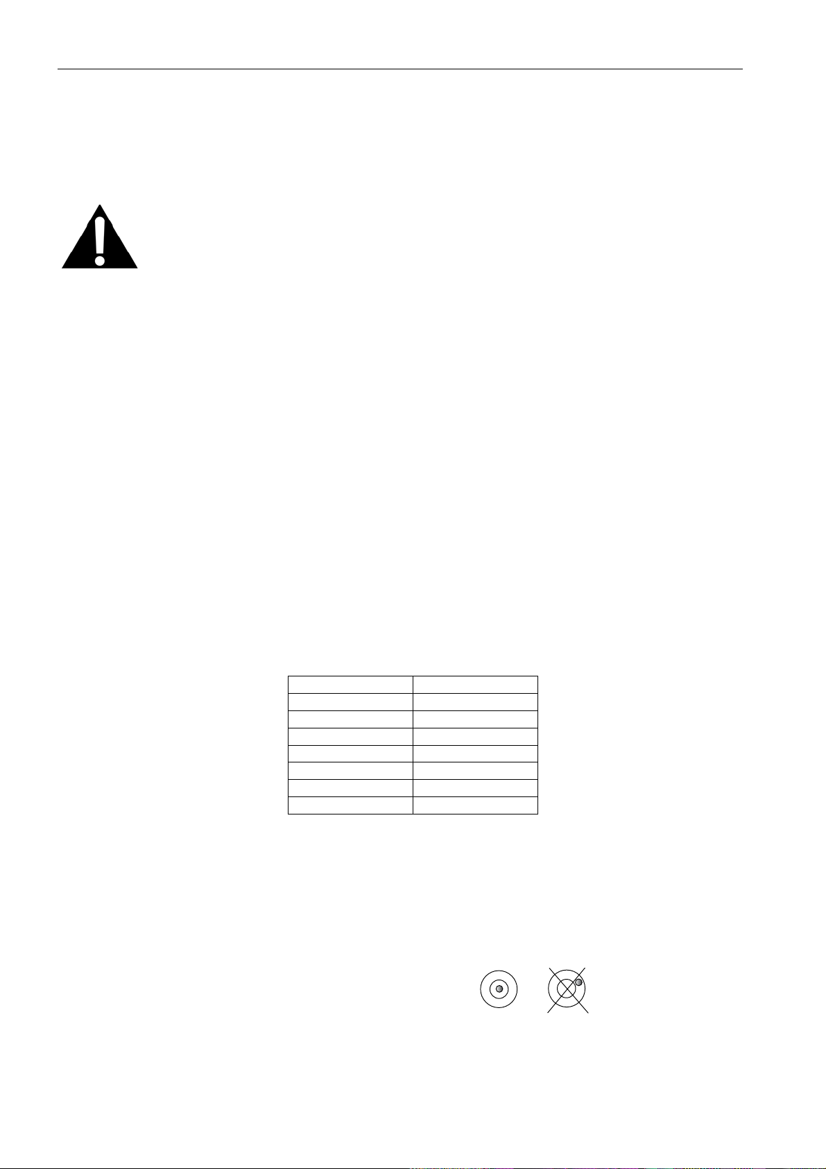
Level the base by adjusting the four leveling feet until the bubble i
A wrench may be needed to loosen the locking nut above each leveling foot. When the base is level, retighten the locking nuts
up against the base to lock each foot into place.
Note: Ensure t
hat the base is level each time its location is changed.
e is already pre-wired to the 3000 Series Indicator.
n the level indicator (located at the rear of the base) is centered.
CORRECT INCORRECT
Find Quality Products Online at: [email protected]
www.GlobalTestSupply.com
Page 5

Defender 3000 Series Base EN-2
MAINTENANCE
Cleaning
The base components should be kept clean and free of excessive material build up.
• Dam
p cloth with water and a mild detergent may be used to wipe clean the external surfaces—do not use acids,
alkalis, strong solvents or abrasive materials and chemicals
Troubleshooting
Aside from installing components and leveling adjustments, the Defender Series Base does not require any other adjustments as
shipped from the factory.
Operational difficulties that may be encountered can ofte
• Loose
• Obstructi
• Unst
• Incorrect cali
or incorrect wiring connections
ons to the base frame
able environments
bration or setup of the indicator
n be traced to simple causes such as:
TECHNICAL DATA
Technical Specifications
The technical data is valid under the following ambient conditions:
Ambient temperature: -10ºC to +40 ºC
Relative humidity: 10% to 90% relative humidity, non-condensing
Height above sea level: Up to 4,000m
Operability is assured at ambient temperature -10ºC to +40 ºC
TABLE 2a. SPECIFICATIONS
MODEL D30BR D60BR D60BL D150BL D150BX D300BX
Capacity 30 kg 60 kg 60 kg 150 kg 150 kg 300 kg
Maximum Resolution 6000d 6000d 6000d 7500d 7500d 6000d
Pan Dimensions 305 x 355 x 75 mm 420 x 550 x 80 mm 500 x 650 x 90 mm
Base Construction Stainless Steel platform with painted steel frame and rubber leveling feet
Safe Overload Capacity 125% of capacity
Repeatability (std. deviation) 1d
Linearity ±1d
Load Cell Cable 2 m L x 6-wire 2.3 m L x 6-wire
Load Cell Type 350 Ohm, aluminum, single point
Load Cell Excitation 5-15V DC/AC
Load Cell Rated Output 2mV/V
Load Cell Protection IP67
Net Weight 9 kg 16 kg 28 kg
Shipping Weight 11 kg 19 kg 32 kg
Find Quality Products Online at: [email protected]
www.GlobalTestSupply.com
Page 6
Defender 3000 Series Base
TABLE 2b. SPECIFICATIONS
MODEL D30VR D60VR D60VL D150VL D150VX D300VX
Capacity 30 kg 60 kg 60 kg 150 kg 150 kg 300 kg
Maximum Resolution 6000d 6000d 6000d 7500d 7500d 6000d
Pan Dimensions 305 x 355 x 75 mm 420 x 550 x 80 mm 500 x 650 x 90 mm
Base Construction Stainless Steel platform with stainless steel frame and rubber leveling feet
Safe Overload Capacity 125% of capacity
Repeatability (std. deviation) 1d
Linearity ±1d
Load Cell Cable 2 m L x 6-wire 2.3 m L x 6-wire
Load Cell Type 350 Ohm, stainless steel, single point
Load Cell Excitation 5-15V DC/AC
Load Cell Rated Output 2mV/V
Load Cell Protection IP67
Net Weight 9 kg 21 kg 33 kg
Shipping Weight 11 kg 24 kg 37 kg
EN-3
Find Quality Products Online at: [email protected]
www.GlobalTestSupply.com
Page 7
Drawings
Defender 3000 Series Base EN-4
Base shown with 3000 ser
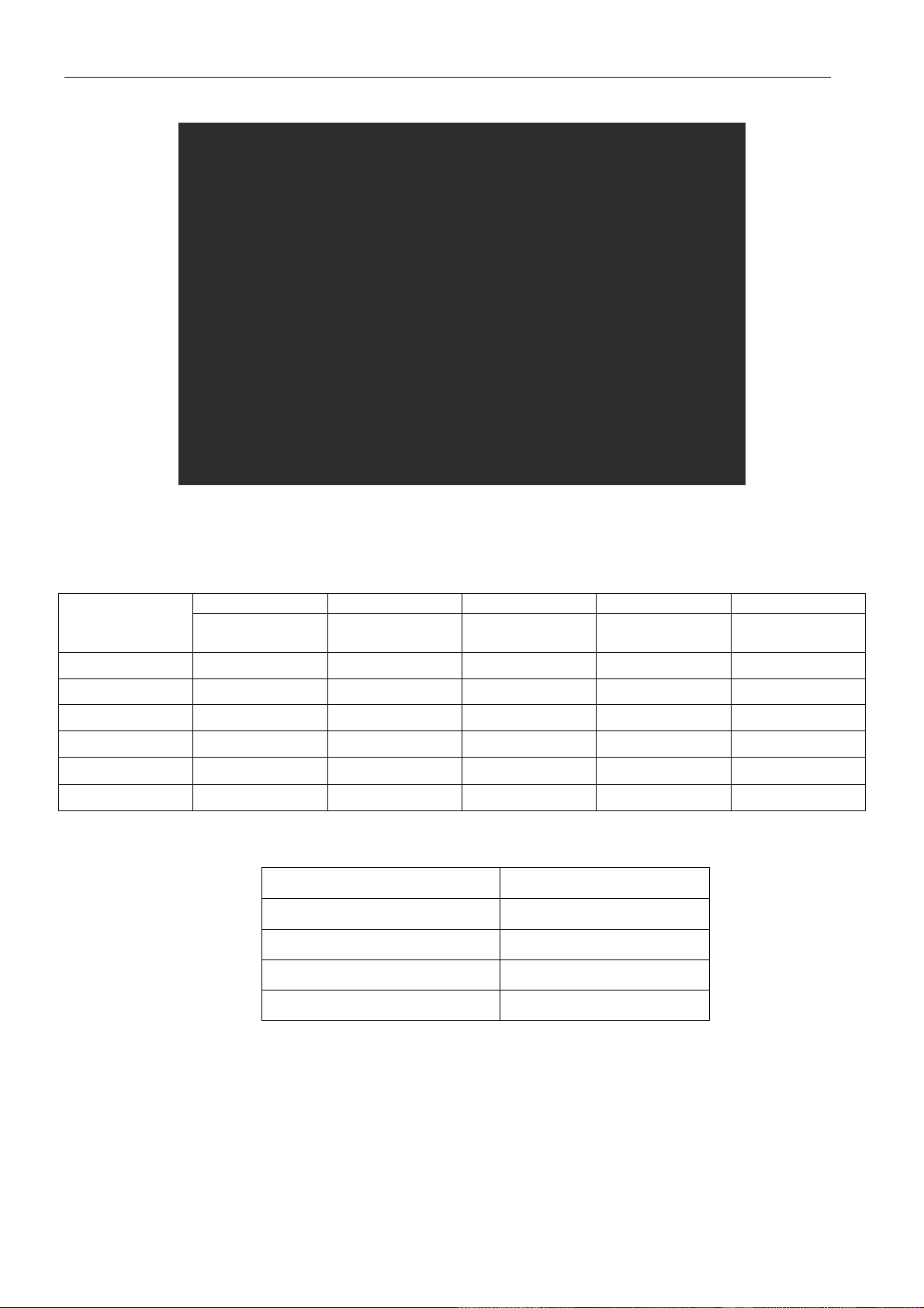
Figure 1. Defender Base Dimension Drawing.
TABLE 3. DIMENSIONS.
A B C D E
Base
D30BR, D60BR 355 mm 305 mm 123 mm 75 mm 380 mm
D60BL, D150BL 550 mm 420 mm 136 mm 80 mm 575 mm
D150BX, D300BX 650 mm 500 mm 143 mm 90 mm 675 mm
D30VR, D60VR 355 mm 305 mm 119 mm 75 mm 380 mm
D60VL, D150VL 550 mm 420 mm 145 mm 80 mm 575 mm
D150VX, D300VX 650 mm 500 mm 154 mm 90 mm 675 mm
*For leveling purposes, the feet may be extended up to an additional 11mm.
Pan Depth Pan Width
TABLE 4. ACCESSORIES.
Description Part Num
Column Kit, 35 cm painted steel 80251743
Column Kit, 70 cm painted steel 80251744
Height of Pan to
rface of Table*
Su
ber
ies indicator and column
Height of Pan
Depth Including
Level Indicator
Column Kit, 35 cm stainless steel 80251745
Column Kit, 70 cm stainless steel 80251746
Find Quality Products Online at: [email protected]
www.GlobalTestSupply.com
Page 8

Defender 3000 Series Base
EN-5
LIMITED WARRANTY
Ohaus products are warranted against defects in materials and workmanship from the date of delivery through the duration of the
warranty period. During the warranty period Ohaus will repair, or, at its option, replace any component(s) that proves to be
defective at no charge, provided that the product is returned, freight prepaid, to Ohaus. This warranty does not apply if the
product has been damaged by accident or misuse, exposed to radioactive or corrosive materials, has foreign material
penetrating to the inside of the product, or as a result of service or modification by other than Ohaus. In lieu of a properly returned
warranty registration card, the warranty period shall begin on the date of shipment to the authorized dealer. No other express or
implied warranty is given by Ohaus Corporation. Ohaus Corporation shall not be liable for any consequential damages.
As warranty legislation differs from state to state and country t
further details.
o country, please contact Ohaus or your local Ohaus dealer for
Find Quality Products Online at: [email protected]
www.GlobalTestSupply.com
Page 9

*80251065*
P/N 80251065 B ©2007 Ohaus Corporation, all rights reserved
Printed in China
Find Quality Products Online at: [email protected]
www.GlobalTestSupply.com
Page 10

Page 11

TABLE OF CONTENTS
1. INTRODUCTION ..........................................................................................................................................EN-4
1.1 Safety Precautions .....................................................................................................................................EN-4
1.2 Overview of Parts and Controls ...................................................................................................................EN-5
1.3 Control Functions .......................................................................................................................................EN-9
2. INSTALLATION .........................................................................................................................................EN-10
2.1 Unpacking .............................................................................................................................................. EN-10
2.2 External Connections ................................................................................................................................EN-10
2.2.1 RS232 Interface Cable to T31P........................................................................................................EN-10
2.2.2 AC Power to T31P ........................................................................................................................EN-10
2.2.3 AC Power to T31XW .......................................................................................................................EN-10
2.2.4 Battery power (T31P) .....................................................................................................................EN-11
2.2.5 Mounting Bracket to T31XW ............................................................................................................EN-11
2.3 Internal Connections .................................................................................................................................EN-11
2.3.1 Opening the Housing .......................................................................................................................EN-11
2.3.2 Scale Base to T31P or T31XW .......................................................................................................EN-12
2.3.3 RS232 Interface Cable to T31XW ......................................................................................................EN-12
2.4 T31P Rear Cover Orientation .....................................................................................................................EN-13
2.5 Direct Wall Mounting (T31P only) .............................................................................................................EN-13
2.6 Mounting Bracket (T31XW only) ................................................................................................................ EN-13
EN-13000 Series Indicators
3. SETTINGS ................................................................................................................................................EN-14
3.1 Menu Structure ........................................................................................................................................EN-14
3.2 Menu Navigation .....................................................................................................................................EN-15
3.3 Calibration Menu .....................................................................................................................................EN-15
3.3.1 Span Calibration ...........................................................................................................................EN-16
3.3.2 Linearity Calibration ......................................................................................................................EN-16
3.3.3 Geographical Adjustment Factor .....................................................................................................EN-17
3.3.4 End Calibration .............................................................................................................................EN-17
3.4 Setup Menu .............................................................................................................................................EN-19
3.4.1 Reset ...........................................................................................................................................EN-19
3.4.2 Legal for trade ..............................................................................................................................EN-19
3.4.3 Calibration Unit .............................................................................................................................EN-19
3.4.4 Capacity ......................................................................................................................................EN-19
3.4.5 Graduation ...................................................................................................................................EN-21
3.4.6 Power On Unit .............................................................................................................................. EN-21
3.4.7 Zero Range ..................................................................................................................................EN-21
3.4.8 End Setup .................................................................................................................................... EN-21
Find Quality Products Online at: [email protected]
www.GlobalTestSupply.com
Page 12

EN-2 3000 Series Indicators
TABLE OF CONTENTS (Cont.)
3.5 Readout Menu ......................................................................................................................................... EN-21
3.5.1 Reset ...........................................................................................................................................EN-21
3.5.2 Filter ............................................................................................................................................EN-22
3.5.3 Auto-Zero Tracking ........................................................................................................................EN-22
3.5.4 Backlight ..................................................................................................................................... EN-22
3.5.5 Auto Off Timer ..............................................................................................................................EN-22
3.5.6 End Readout ................................................................................................................................. EN-22
3.6 Mode Menu .............................................................................................................................................EN-23
3.6.1 Reset ...........................................................................................................................................EN-23
3.6.2 Parts Counting Mode .....................................................................................................................EN-23
3.6.3 End Mode .................................................................................................................................... EN-23
3.7 Unit Menu ...............................................................................................................................................EN-24
3.7.1 Reset ...........................................................................................................................................EN-24
3.7.2 Kilogram Unit ............................................................................................................................... EN-24
3.7.3 Pound Unit ...................................................................................................................................EN-24
3.7.4 Gram Unit .................................................................................................................................... EN-24
3.7.5 Ounce Unit ...................................................................................................................................EN-24
3.7.6 Pound Ounce Unit .........................................................................................................................EN-24
3.7.7 End Unit ......................................................................................................................................EN-24
3.8 Print Menu ..........................................................................................................................................EN-25
3.8.1 Reset ...........................................................................................................................................EN-25
3.8.2 Baud ........................................................................................................................................... EN-25
3.8.3 Parity .......................................................................................................................................... EN-25
3.8.4 Stop Bit .......................................................................................................................................EN-25
3.8.5 Handshake ..................................................................................................................................EN-26
3.8.6 Print Stable Data Only ...................................................................................................................EN-26
3.8.7 Auto Print .....................................................................................................................................EN-26
3.8.8 Content ........................................................................................................................................EN-26
3.8.9 End Print .....................................................................................................................................EN-26
3.9 Menu Lock Menu .....................................................................................................................................EN-27
3.9.1 Reset ...........................................................................................................................................EN-27
3.9.2 Lock Calibration ...........................................................................................................................EN-27
3.9.3 Lock Setup ...................................................................................................................................EN-27
3.9.4 Lock Readout ............................................................................................................................... EN-27
3.9.5 Lock Mode ...................................................................................................................................EN-27
3.9.6 Lock Unit .....................................................................................................................................EN-27
3.9.7 Lock Print ...................................................................................................................................EN-28
3.9.8 End Lock .....................................................................................................................................EN-28
Find Quality Products Online at: [email protected]
www.GlobalTestSupply.com
Page 13

TABLE OF CONTENTS (Cont.)
3.10 Security Switch .......................................................................................................................................EN-28
4. OPERATION ............................................................................................................................................. EN-28
4.1 Turning Indicator On/Off ............................................................................................................................EN-28
4.2 Zero Operation .........................................................................................................................................EN-28
4.3 Manual Tare ............................................................................................................................................EN-28
4.4 Changing Units of Measure .......................................................................................................................EN-29
4.5 Printing Data ........................................................................................................................................... EN-29
4.6 Application Modes ...................................................................................................................................EN-29
4.6.1 Weighing .....................................................................................................................................EN-29
4.6.2 Parts Counting .............................................................................................................................EN-29
5. SERIAL COMMUNICATION ..........................................................................................................................EN-31
5.1 Interface Commands ................................................................................................................................EN-31
5.2 Output Format .........................................................................................................................................EN-32
6. LEGAL FOR TRADE ...................................................................................................................................EN-33
6.1 Settings .................................................................................................................................................. EN-33
6.2 Verification ..............................................................................................................................................EN-33
6.3 Sealing ...................................................................................................................................................EN-33
6.3.1 Physical Seals ..............................................................................................................................EN-33
6.3.2 Audit Trail Seal .............................................................................................................................EN-34
EN-33000 Series Indicators
7. MAINTENANCE .........................................................................................................................................EN-36
7.1 Model T31P Cleaning ...............................................................................................................................EN-36
7.2 Model T31XW Cleaning ............................................................................................................................EN-36
7.3 Troubleshooting ....................................................................................................................................... EN-34
7.4 Service Information ..................................................................................................................................EN-37
8. TECHNICAL DATA .....................................................................................................................................EN-38
8.1 Specifications ..........................................................................................................................................EN-38
8.2 Accessories and Options ........................................................................................................................... EN-39
8.3 Drawings and Dimensions ........................................................................................................................EN-40
8.4 Compliance .............................................................................................................................................EN-41
Find Quality Products Online at: [email protected]
www.GlobalTestSupply.com
Page 14

EN-4 3000 Series Indicators
1. INTRODUCTION
This manual contains installation, operation and maintenance instructions for the T31P and T31XW Indicators. Please read this
manual completely before installation and operation.
1.1 Safety Precautions
For safe and dependable operation of this equipment, please comply with the following safety precautions:
• Verify that the input voltage range printed on the data label matches the local AC power to be used.
• Make sure that the power cord does not pose a potential obstacle or tripping hazard.
• Use only approved accessories and peripherals.
• Operate the equipment only under ambient conditions specified in these instructions.
• Disconnect the equipment from the power supply before cleaning.
• Do not operate the equipment in hazardous or unstable environments.
• Do not immerse the equipment in water or other liquids.
• Service should only be performed by authorized personnel.
• The T31XW is supplied with a grounded power cable. Use only with a compatible grounded power outlet.
Find Quality Products Online at: [email protected]
www.GlobalTestSupply.com
Page 15
1.2 Overview of Parts and Controls
3
000
SERIES
On/Zero
Off
Yes
CALIBRATION
MODE
Print
Units
No
´0³
PCS NET TARE
Function
Mode
Back
Tare
Menu
EN-53000 Series Indicators
1
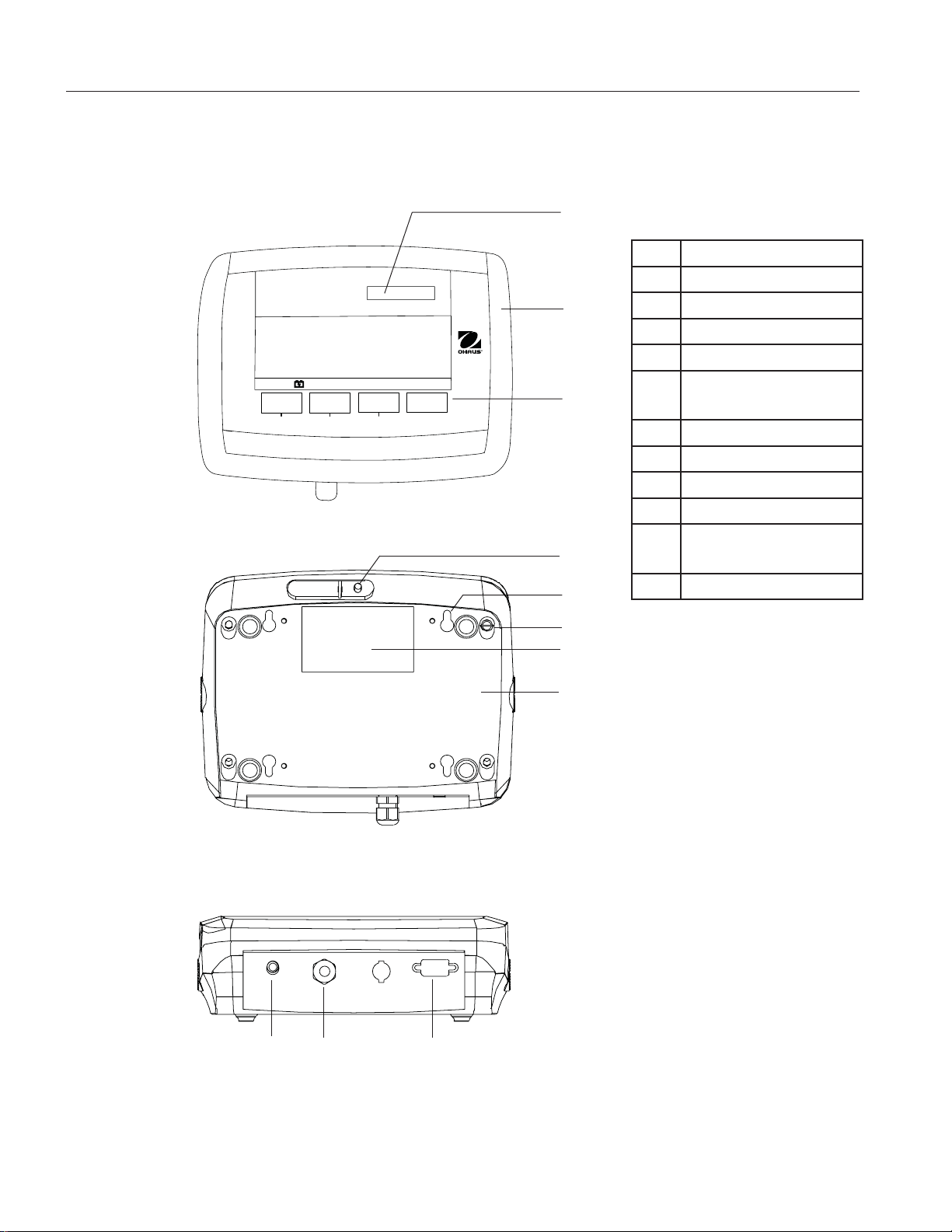
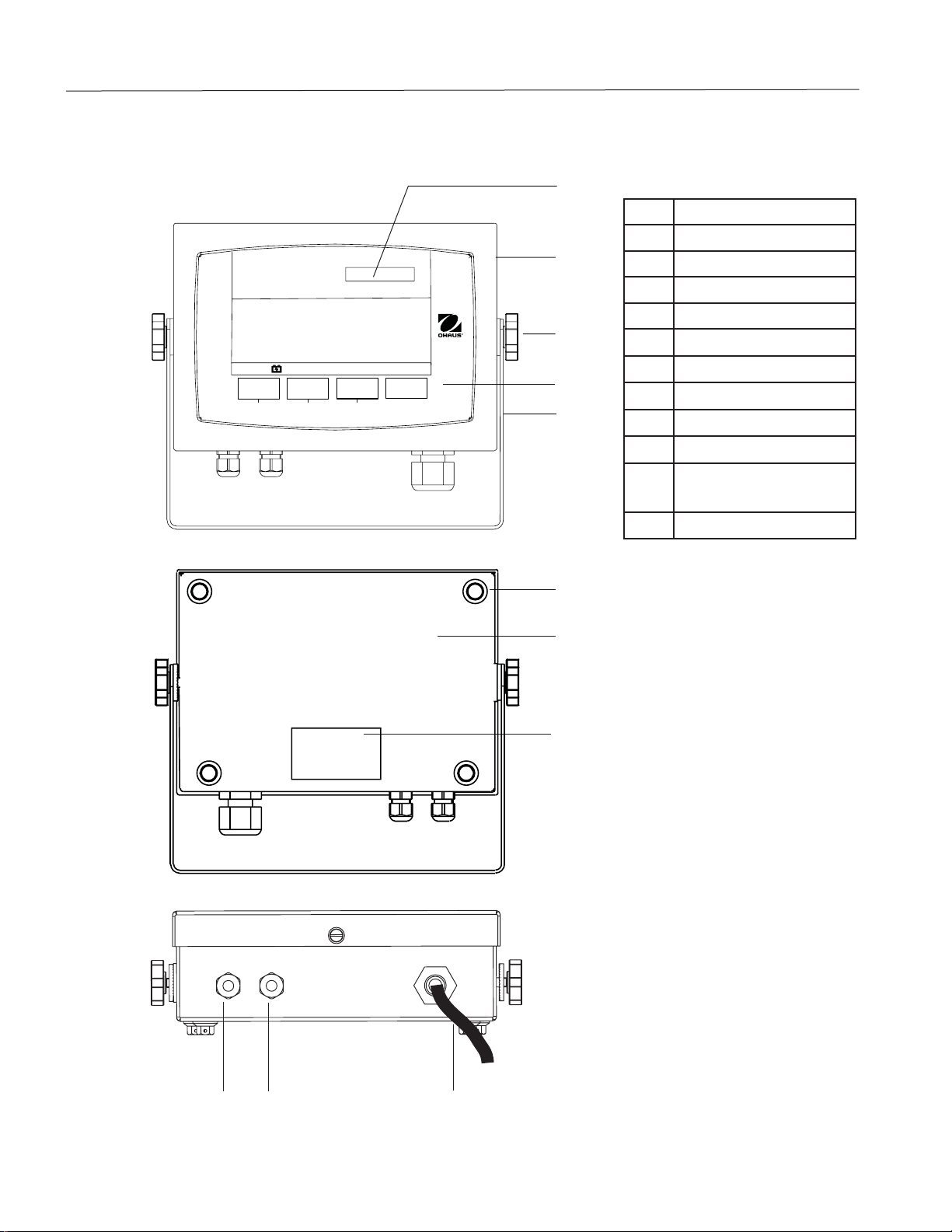
TABLE 1-1. T31P PARTS.
Item Description
1 Data Label
2
3
Exit
4
5
2 Front Housing
3 Control Panel
4 Security Screw
5 Key Hole (4) for wall
mounting
6 Screw (4)
7 Data Label
8 Rear Housing
9 Power Receptacle
10 Strain Relief for Load Cell
Cable
11 RS232 Connector
910
6
7
8
11
Figure 1-1. T31P Indicator.
Find Quality Products Online at: [email protected]
www.GlobalTestSupply.com
Page 16
EN-6 3000 Series Indicators
1.2 Overview of Parts and Controls (Cont.)
3000SERIESXTREMEW
CALIBRATION
´0³
On/Zero
Off
Yes
MODE
Print
Units
No
PCS NE T TA RE
Function
Mode
Back
Tare
Menu
Exit
1
TABLE 1-2. T31XW PARTS.
Item Description
1 Data Label
2
2 Front Housing
3 Adjusting Knob (2)
4 Control Panel
3
4
5 Mounting Bracket
6 Screw (4)
7 Rear Housing
5
8 Data Label
9 Strain Relief for RS232
10 Strain Relief for Load Cell
Cable
11 Power cord
6
7
8
910
11
Figure 1-2. T31XW Indicator.
Find Quality Products Online at: [email protected]
www.GlobalTestSupply.com
Page 17

1.2 Overview of Parts and Controls (Cont.)
EN-73000 Series Indicators
J4
1
2
3
LOAD CELL WIRING
J5
W1 W2
45
Figure 1-3. Main PC Board.
6
OFF
J7 J6
7
TABLE 1-3. MAIN PC BOARD.
Item Description
1 Keypad Connector J4 T31XW Model only
2 Battery Connector (T31P only)
ON
8
9
+EXC +SIG -SIG -EXC
+SENS GND -SENS
RS232 WIRING
TXD GND
RXD
3 Line Power Input
4 Sense Jumper W1
5 Load Cell Terminal Block J5
6 Sense Jumper W2
7 RS232 Terminal Block J7 T31XW Model only
8 RS232 Connector J6 T31P Model only
9 LFT On / Off Switch
Find Quality Products Online at: [email protected]
www.GlobalTestSupply.com
Page 18

EN-8 3000 Series Indicators
1.2 Overview of Parts and Controls (Cont.)
1
9
11 2
10
8
7
6
Figure 1-4. Controls and Indicators.
TABLE 1-4. CONTROL PANEL.
No. Designation
1 Capacity Label Window
2 TARE
3 TARE symbol
4 FUNCTION
5 NET symbol
6 PCS symbol
7 PRINT
8 Calibration Mode symbol
9 Battery symbol (T31P only)
10 ON/ZERO
11 Center of Zero symbol
Menu
Units
5
button
Mode
button
Off
button
4
button
3
Find Quality Products Online at: [email protected]
www.GlobalTestSupply.com
Page 19

1.3 Control Functions
EN-93000 Series Indicators
TABLE 1-5. CONTROL FUNCTIONS.
Button
Primary Function
(Short Press)
Secondary Function
(Long Press)
Menu Function
(Short Press)
On/Zero
Off
Yes
ON/ZERO
If Indicator is On, sets
zero.
Off
Turns the Indicator on
or off.
Yes
Accepts the current
setting on the display.
Print
Units
No
PRINT
Sends the current value
to the COM port if
AUTOPRINT is set to Off.
Units
Changes the weighing
Unit.
No
Advances to the next
menu or menu item.
Rejects the current
setting on the display
and advances to the
next available setting.
Increments the value.
Function
Mode
Back
FUNCTION
Initiates an application
mode.
Mode
Allows changing the
application mode.
Press and hold allows
scrolling through modes.
Back
Moves Back to previous
menu item.
Decrements the value.
Tare
Menu
Exit
TARE
Performs a tare
operation.
Menu
Enter the User menu.
View the Audit Trail event
counters (extended
press)
Exit
Exits the User menu.
Aborts the calibration in
progress.
Find Quality Products Online at: [email protected]
www.GlobalTestSupply.com
Page 20
EN-10 3000 Series Indicators
2. INSTALLATION
2.1 Unpacking
Unpack the following items:
• T31P or T31XW Indicator
• AC Adapter (T31P only)
• Mounting Bracket (supplied with T31XW only)
• Knobs (2) (supplied with T31XW only)
• Capacity Label Sheet
• Instruction Manual CD
• Warranty Card
• LFT sealing Kit
2.2 External Connections
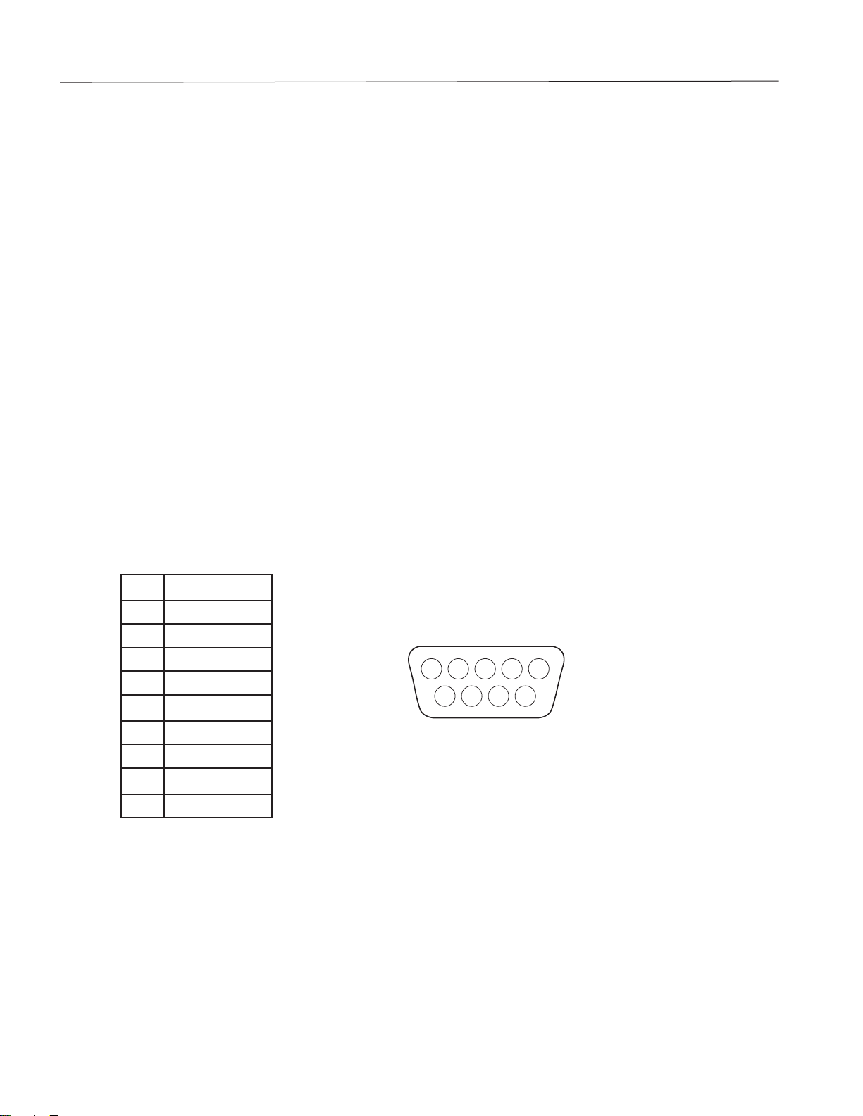
2.2.1 RS232 interface Cable to T31P
Connect the optional RS232 cable to the RS232 connector Figure 1-1, item 13).
Pin Connection
1 N/C
2 TXD
3 RXD
4 N/C
5 GND
6 N/C
7 N/C
8 N/C
9 N/C
4
5
9
Figure 2-1. RS232 Pins.
2
3
1
78
6
2.2.2 AC Power to T31P
Connect the AC Adapter to the power receptacle (Figure 1-1, item 8), then plug the AC Adapter into an electrical outlet.
2.2.3 AC Power to T31XW
Connect the AC plug to a properly grounded electrical outlet.
Find Quality Products Online at: [email protected]
www.GlobalTestSupply.com
Page 21

EN-113000 Series Indicators
2.2.4 Battery Power (T31P Only)
The indicator can be operated on the internal rechargeable battery when AC power is not available. The indicator will
automatically switch to battery operation if there is a power failure or the power cord is removed.
Note:
Before using the indicator for the first time, the internal rechargeable battery should be fully charged for up to
12 hours. The indicator can be operated during the charging process. The battery is protected against over
charging and the indicator can remain connected to the AC power line.
Connect AC power to the indicator and allow it to charge. While the battery is charging, the triangle above the battery function
symbol will light. When the battery is fully charged, this triangle will disappear.
The indicator can operate for up to 100 hours on a fully charged battery.
During battery operation, a flashing triangle above the battery function symbol indicates the battery is low and requires
recharging. Approximately 60 minutes of operation will remain when the battery symbol starts to blink. The indicator will
display Lo.BAT and automatically turn off when the battery is fully discharged.
CAUTION
BATTERY IS TO BE REPLACED ONLY BY AN AUTHORIZED OHAUS
SERVICE DEALER.
RISK OF EXPLOSION CAN OCCUR IF REPLACED WITH THE
WRONG TYPE OR CONNECTED IMPROPERLY.
Dispose of the lead acid battery according to local laws and regulations.
2.2.5 Mounting Bracket to T31XW
Align the mounting bracket over the threaded holes in the side of the indicator and install the knobs. Adjust the indicator to the
desired angle and tighten the knobs.
2.3 Internal Connections
Some connections require the housing to be opened.
2.3.1 Opening the Housing
CAUTION: ELECTRICAL SHOCK HAZARD. REMOVE ALL POWER CONNECTIONS TO THE INDICATOR
BEFORE SERVICING OR MAKING INTERNAL CONNECTIONS. THE HOUSING SHOULD ONLY BE OPENED
BY AUTHORIZED AND QUALIFIED PERSONNEL, SUCH AS AN ELECTRICAL TECHNICIAN.
Find Quality Products Online at: [email protected]
www.GlobalTestSupply.com
Page 22
EN-12 3000 Series Indicators
T31P
Remove the four Phillips head screws from the rear housing.
Open the housing being careful not to disturb the internal connections.
Once all connections are made, reattach the front housing.
T31XW
Remove the four hex head screws from the rear housing.
Open the housing by carefully pulling the top of the front housing forward.
Once all connections are made, reattach the front housing.
The screws should be tightened fully to maintain a watertight seal.
2.3.2 Scale Base to T31P or T31XW
Pass the load cell cable through the strain relief (Figure 1-1, item 9 or Figure 1-2,
item 10) and attach it to terminal block J5 (Figure 1-3, item 5).
Re-tighten the strain relief to ensure a watertight seal.
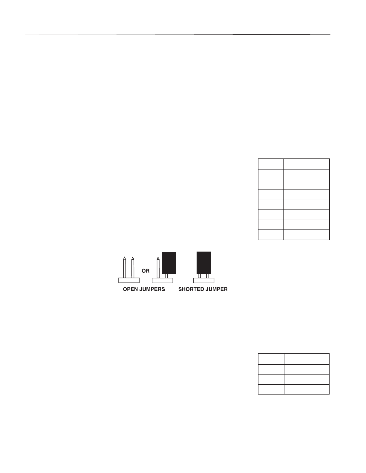
Jumper Connections
For a 4-wire load cell with no sense wires: Jumpers W2 and W3 must be shorted.
For a 6-wire load cell that includes sense wires, see Figure 2-2. Jumpers W2 and W3 must
be opened.
For load cells with an extra ground shield wire: Connect the shield to the center position (GND)
of J5.
Pin Connection
J5-1 +EXCITATION
J5-2 +SENSE
J5-3 +SIGNAL
J5-4 GND
J5-5 -SIGNAL
J5-6 -SENSE
J5-7 -EXCITATION
Figure 2-2. Jumper Connections.
After wiring is completed and jumpers are in place, replace the indicator housing screws. Make sure the strain relief is properly
tightened.
2.3.3 RS232 Interface Cable to T31XW
Pass the optional RS232 cable through the strain relief (Figure 1-2, item 9) and attach it to
terminal block J7 (Figure 1-3, item 7). Re-tighten the strain relief to ensure a water tight seal.
Find Quality Products Online at: [email protected]
www.GlobalTestSupply.com
Pin Connection
J7-1 TXD
J7-2 RXD
J7-3 GND
Page 23
EN-133000 Series Indicators
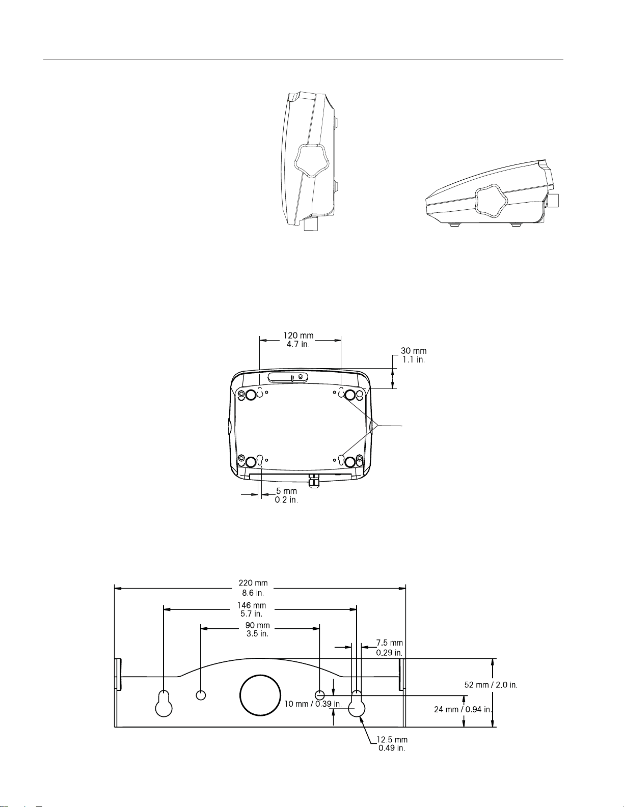
2.4 T31P Rear Cover Orientation
The T31P is delivered in the wall mount orientation
with the connections exiting below the display. The
rear housing may be reversed so the connections
exit above the display when the T31P is placed
horizontally on a bench. See Figure 2-4. To reverse
the rear housing, remove the four Phillips head
screws, carefully rotate the housing 180°, and
reinstall the screws.
CAUTION: Take care not to pinch any internal
cables attached inside.
Figure 2-3. Wall Mount Configuration.
Figure 2-4. Bench Top Configuration.
2.5 Direct Wall Mounting (T31P only)
The T31P indicator may be mounted directly to a wall using two screws (not included). Select appropriate size screws that fit
into the holes at the bottom of the indicator housing. See Figure 2-5. When mounting to a wall without a solid backing, use
appropriate anchoring hardware.
Wall Mounting Holes
Figure 2-5. T31P Direct Wall Mounting.
2.6 Mounting Bracket (T31XW only)
Attach the bracket to a wall or table using fasteners (not supplied) that are appropriate for the type of mounting surface. The
bracket will accommodate up to 6 mm (1/4”) diameter screws. Locate the mounting holes as shown in Figure 2-6.
Figure 2-6. Mounting Bracket Dimensions.
Find Quality Products Online at: [email protected]
www.GlobalTestSupply.com
Page 24
3 SETTINGS
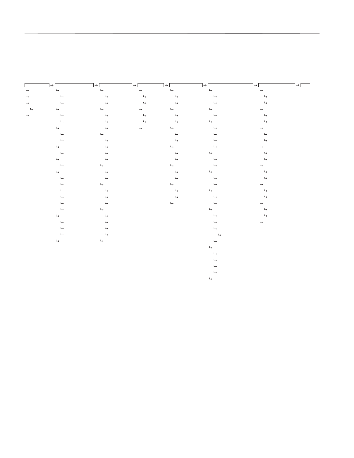
3.1 Menu Structure
TABLE 3-1. MENU STRUCTURE.
CALIBRATION SETUP READOUT MODE UNIT
SPAN RESET RESET RESET RESET
LINEARITY NO NO NO NO
GEO YES YES YES YES
0…31 LEGAL FOR TRADE AVERAGING COUNT KILOGRAM
END CAL OFF LOW OFF OFF
ON MEDIUM ON ON
CALIBRATION UNIT HI END MODE POUND
KILOGRAM OREZ OTUA OFF
POUND FFO ON
CAPACITY 0.5d GRAM
5…20000 d1 OFF
GRADUATION d3 ON
0.001…20 EXPAND MODE OUNCE
POWER ON UNIT FFO OFF
AUTO NO ON
GRAM BACKLIGHT POUND OUNCE
KILOGRAM OTUA OFF
POUND NO ON
OUNCE OFF END UNIT
POUND OUNCE AUTO OFF
ZERO RANGE OFF
0% SET 1
2% SET 2
100% SET 5
END SETUP END READOUT
PRINT MENU LOCK END
RESET RESET
NO NO
YES YES
BAUD LOCK CAL
300, …19200 OFF
PARITY
7 EVEN LOCK SETUP
7 ODD OFF
7 NONE ON
8 NONE LOCK READOUT
STOP OFF
1 ON
2 LOCK MODE
HANDSHAKE OFF
OFF ON
XON-XOFF LOCK UNIT
STABLE ONLY OFF
OFF ON
ON LOCK PRINT
AUTO PRINT OFF
OFF ON
WHEN STABLE END MENU LOCK
INTERVAL
1…3600
CONTINUOUS
CONTENT
GROSS
NET
TARE
UNIT
END PRINT
ON
srotacidnI seireS 000341-NE
Find Quality Products Online at: [email protected]
www.GlobalTestSupply.com
Page 25

3.2 Menu Navigation
TO ENTER THE MENU MODE
Press and hold the Menu button until MENU appears on the display. The first upper level menu appears on the display.
Summary of button navigation functions in menu mode:
--Yes Allows entry into the displayed menu.
- Accepts the displayed setting and advances to the next menu item.
--No Skips by the displayed menu.
- Rejects the displayed setting or menu item and advances to the next available item.
--Back Moves backwards through the upper and middle level menus.
- Backs out of a list of selectable items to the previous middle level menu.
--Exit Exits from menu directly to the active weighing mode.
3.3 Calibration Menu
Two calibration processes are available: Span Calibration and Linearity
Calibration.
NOTES:
1. Make sure that appropriate calibration masses are available before
beginning calibration.
2. Make sure that the scale base is level and stable during the entire
calibration process.
3. Calibration is unavailable with LFT set to On.
4. Allow the Indicator to warm up for approximately 5 minutes after
stabilizing to room temperature.
5. To abort calibration, press the Exit button anytime during the calibration
process.
Span Perform
Linearity Perform
Geographic
Adjustment Set 00…Set 19… Set 31
End Calibration Exit CALIBRATE menu
EN-153000 Series Indicators
Find Quality Products Online at: [email protected]
www.GlobalTestSupply.com
Page 26

EN-16 3000 Series Indicators
3.3.1 Span Calibration
Span Calibration uses two points to adjust the scale. The first point is the zero value where there is no weight
on the scale. The second point is the Span value where a calibration mass is placed on the scale.
When SPAN is displayed, press the Yes button to access the Span Calibration menu item.
The display flashes 0.
With no weight on the scale, press the Yes button to establish the zero point.
The display shows --C-- while the zero point is established.
The display flashes the span calibration point. Place the specified weight on the scale and press the Yes
button.
To choose a different span point, repeatedly press the No button to increment the selections or press the Back
button to decrement the selections. Refer to Table 3-3 for available span points. When the desired value is
displayed, place the specified weight on the scale and press the Yes button.
The display shows --C-- while the span point is established.
If span calibration was successful, the scale exits to the active weighing mode and displays the actual weight
value.
3.3.2 Linearity Calibration
Linearity calibration uses 3 calibration points. The first calibration point is established with no weight on the
scale. The second calibration point is established at approximately half capacity. The third calibration point
is established at capacity. The Linearity calibration points are fixed and cannot be altered by the user during
the calibration procedure. Refer to Table 3-3 for the linearity points.
When LINEAr is displayed, press the Yes button to access the Linearity Calibration menu item.
The display flashes 0. With no weight on the scale, press the Yes button to establish the zero point.
The display shows --C-- while the zero point is established.
The display flashes the mid calibration point.
Place the specified weight on the scale and press the Yes button.
The display shows --C-- while the mid point is established.
Å
The display flashes the full calibration point.
Place the specified weight on the scale and press the Yes button.
The display shows --C-- while the full point is established.
If linearity calibration was successful, the scale exits to the active weighing mode and displays the actual
weight value.
Find Quality Products Online at: [email protected]
www.GlobalTestSupply.com
Å
Page 27
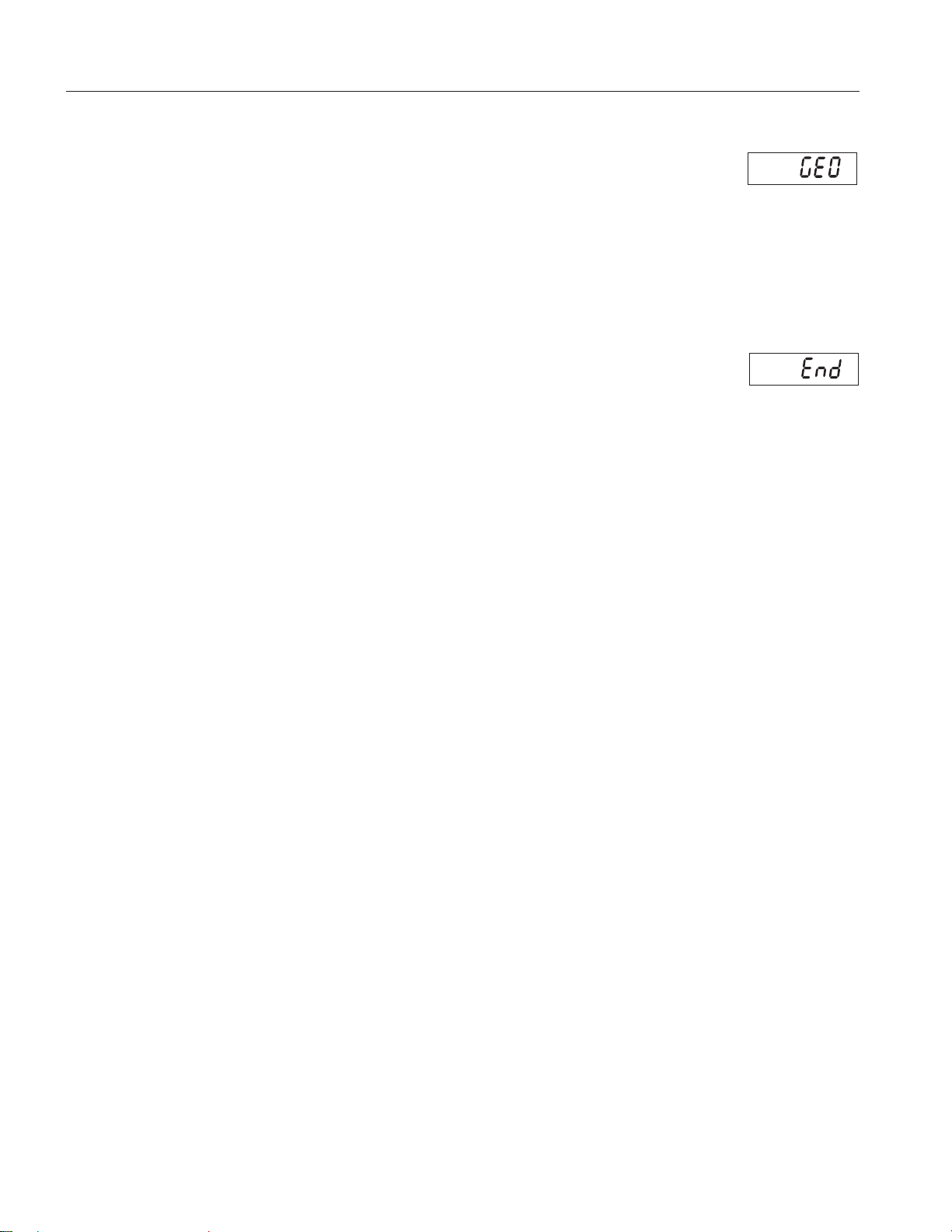
3.3.3 Geographical Adjustment Factor
The Geographcial Adjustment Factor (GEO) is used to compensate for variations in gravity.
Note: Changing the GEO Factor alters the calibration. The GEO value was set at the factory and should only
be changed by an authorized manufacturer’s representative or certified verirication personnel.
Refer to table 3-2 to determine the GEO factor that corresponds to your location.
3.3.4 End Calibration
Advance to the next menu.
EN-173000 Series Indicators
Find Quality Products Online at: [email protected]
www.GlobalTestSupply.com
Page 28

EN-18 3000 Series Indicators
TABLE 3-2. GEOGRAPHICAL ADJUSTMENT VALUES
Elevation in meters
0 325 650 975 1300 1625 1950 2275 2600 2925 3250
325 650 975 1300 1625 1950 2275 2600 2925 3250 3575
Elevation in feet
0 1060 2130 3200 4260 5330 6400 7460 8530 9600 10660
1060 2130 3200 4260 5330 6400 7460 8530 9600 10660 11730
Latitude GEO value
0°00’ 5°46’ 54433221100
5°46’ 9°52’ 55443322110
9°52’ 12°44’ 65544332211
12°44’ 15°06’ 66554433221
15°06’ 17°10’ 76655443322
17°10’ 19°02’ 77665544332
19°02’ 20°45’ 87766554433
20°45’ 22°22’ 88776655443
22°22’ 23°54’ 98877665544
23°54’ 25°21’ 99887766554
25°21’ 26°45’ 10 9988776655
26°45’ 28°06’ 10 10 998877665
28°06’ 29°25’ 11 10 10 99887766
29°25’ 30°41’ 11 11 10 10 9988777
30°41’ 31°56’ 12 11 11 10 10 998877
31°56’ 33°09’ 12 12 11 11 10 10 99887
33°09’ 34°21’ 13 12 12 11 11 10 10 9988
34°21’ 35°31’ 13 13 12 12 11 11 10 10 9 9 8
35°31’ 36°41’ 14 13 13 12 12 11 11 10 10 9 9
36°41’ 37°50’ 14 14 13 13 12 12 11 11 10 10 9
37°50’ 38°58’ 15 14 14 13 13 12 12 11 11 10 10
38°58’ 40°05’ 15 15 14 14 13 13 12 12 11 11 10
40°05’ 41°12’ 16 15 15 14 14 13 13 12 12 11 11
41°12’ 42°19’ 16 16 15 15 14 14 13 13 12 12 11
42°19’ 43°26’ 17 16 16 15 15 14 14 13 13 12 12
43°26’ 44°32’ 17 17 16 16 15 15 14 14 13 13 12
44°32’ 45°38’ 18 17 17 16 16 15 15 14 14 13 13
45°38’ 46°45’ 18 18 17 17 16 16 15 15 14 14 13
46°45’ 47°51’ 19 18 18 17 17 16 16 15 15 14 14
47°51’ 48°58’ 19 19 18 18 17 17 16 16 15 15 14
48°58’ 50°06’ 20 19 19 18 18 17 17 16 16 15 15
50°06’ 51°13’ 20 20 19 19 18 18 17 17 16 16 15
51°13’ 52°22’ 21 20 20 19 19 18 18 17 17 16 16
52°22’ 53°31’ 21 21 20 20 19 19 18 18 17 17 16
53°31’ 54°41’ 22 21 21 20 20 19 19 18 18 17 17
54°41’ 55°52’ 22 22 21 21 20 20 19 19 18 18 17
55°52’ 57°04’ 23 22 22 21 21 20 20 19 19 18 18
57°04’ 58°17’ 23 23 22 22 21 21 20 20 19 19 18
58°17’ 59°32’ 24 23 23 22 22 21 21 20 20 19 19
59°32’ 60°49’ 24 24 23 23 22 22 21 21 20 20 19
60°49’ 62°90’ 25 24 24 23 23 22 22 21 21 20 20
62°90’ 63°30’ 25 25 24 24 23 23 22 22 21 21 20
63°30’ 64°55’ 26 25 25 24 24 23 23 22 22 21 21
64°55’ 66°24’ 26 26 25 25 24 24 23 23 22 22 21
66°24’ 67°57’ 27 26 26 25 25 24 24 23 23 22 22
67°57’ 69°35’ 27 27 26 26 25 25 24 24 23 23 22
69°35’ 71°21’ 28 27 27 26 26 25 25 24 24 23 23
71°21’ 73°16’ 28 28 27 27 26 26 25 25 24 24 23
73°16’ 75°24’ 29 28 28 27 27 26 26 25 25 24 24
75°24’ 77°52’ 29 29 28 28 27 27 26 26 25 25 24
77°52’ 80°56’ 30 29 29 28 28 27 27 26 26 25 25
80°56’ 85°45’ 30 30 29 29 28 28 27 27 26 26 25
85°45’ 90°00’ 31 30 30 29 29 28 28 27 27 26 26
Find Quality Products Online at: [email protected]
www.GlobalTestSupply.com
Page 29
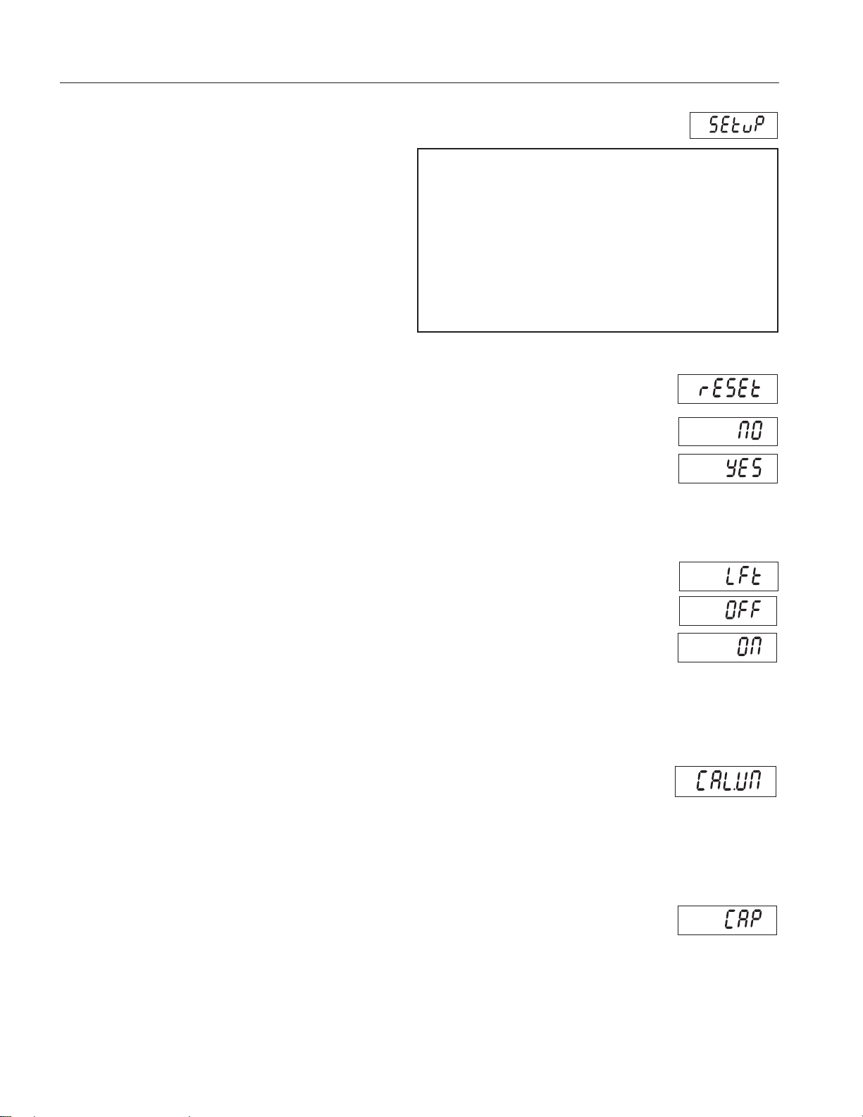
3.4 Setup Menu
EN-193000 Series Indicators
When the Indicator is used for the first time, enter this
menu to set the Capacity and Graduation.
Reset No, Yes
Legal for Trade Off, On
Cal Unit kg, lb
Capacity 5…20000
Graduation 0.001…20
Power On Unit g, kg, lb, oz, lb:oz, Auto
Zero Range 0%, 2%, 100%
End Setup Exit SETUP menu
3.4.1 Reset
Reset the Setup menu to the factory defaults.
No = not reset.
Yes = reset.
NOTE: If the Legal for Trade menu item is set to ON, the Capacity, Graduation, Zero Range and Legal For
Trade settings are not reset.
3.4.2 Legal for Trade
Set the legal for trade status.
OFF = off
ON = on
Turning on the “LFT” menu setting has the following effects:
• Zero-range is set and locked on “2”.
• Auto Zero Tracking is set and locked on 0.5d
• The lb:oz unit is not available as a power-on setting.
3.4.3 Calibration Unit
Set the unit during calibration.
CAL UN kg = Calibrate using kg weights
CAL UN lb = Calibrate using pound weights
3.4.4 Capacity
Set the scale capacity from 5 to 20000. Refer to the Setup Table 3.3 for available settings.
Find Quality Products Online at: [email protected]
www.GlobalTestSupply.com
Page 30

EN-20 3000 Series Indicators
TABLE 3-3. SETUP AND CALIBRATION VALUES
Capacity Graduation size
5 0.0005, 0.001, 0.002,
10 0.0005, 0.001, 0.002,
15 0.001, 0.002, 0.005, 0.01 0.005, 0.01 5, 10, 15 5, 15
20 0.001, 0.002, 0.005, 0.01,
25 0.002, 0.005, 0.01, 0.02 0.005, 0.01, 0.02 5, 10, 15, 20, 25 10, 25
30 0.002, 0.005, 0.01, 0.02 0.005, 0.01, 0.02 5, 10, 15, 20, 25, 30 15, 30
40 0.002, 0.005, 0.01, 0.02 0.01, 0.02 5, 10, 15, 20, 25, 30, 40 20, 40
50 0.005, 0.01, 0.02, 0.05 0.01, 0.02, 0.05 5, 10, 15, 20, 25, 30, 40, 50 25, 50
60 0.005, 0.01, 0.02, 0.05 0.01, 0.02, 0.05 5, 10, 15, 20, 25, 30, 40, 50, 60 30, 60
75 0.005, 0.01, 0.02, 0.05 0.02, 0.05 5, 10, 15, 20, 25, 30, 40, 50, 60, 75 30, 75
100 0.005, 0.01, 0.02, 0.05,
120 0.01, 0.02, 0.05, 0.1 0.02, 0.05, 0.1 5, 10, 15, 20, 25, 30, 40, 50, 60, 75, 100, 120 60, 120
150 0.01, 0.02, 0.05, 0.1 0.05, 0.1 5, 10, 15, 20, 25, 30, 40, 50, 60, 75, 100, 120, 150 75, 150
200 0.02, 0.01, 0.02, 0.05,
250 0.05, 0.1, 0.2 0.05, 0.1, 0.2 5, 10, 15, 20, 25, 30, 40, 50, 60, 75, 100, 120, 150, 200,
300 0.02, 0.05, 0.1, 0.2 0.05, 0.1, 0.2 5, 10, 15, 20, 25, 30, 40, 50, 60, 75, 100, 120, 150, 200,
400 0.02, 0.05, 0.1, 0.2 0.1, 0.2 5, 10, 15, 20, 25, 30, 40, 50, 60, 75, 100, 120, 150, 200,
500 0.05, 0.1, 0.2, 0.5 0.1, 0.2, 0.5 5, 10, 15, 20, 25, 30, 40, 50, 60, 75, 100, 120, 150, 200,
600 0.05, 0.1, 0.2, 0.5 0.1, 0.2, 0.5 5, 10, 15, 20, 25, 30, 40, 50, 60, 75, 100, 120, 150, 200,
750 0.05, 0.1, 0.2, 0.5 0.2, 0.5 5, 10, 15, 20, 25, 30, 40, 50, 60, 75, 100, 120, 150, 200,
1000 0.05, 0.1, 0.2, 0.5, 1 0.2, 0.5, 1 5, 10, 15, 20, 25, 30, 40, 50, 60, 75, 100, 120, 150, 200,
1200 0.1, 0.2, 0.5, 1 0.2, 0.5, 1 5, 10, 15, 20, 25, 30, 40, 50, 60, 75, 100, 120, 150, 200,
1500 0.1, 0.2, 0.5, 1 0.5, 1 5, 10, 15, 20, 25, 30, 40, 50, 60, 75, 100, 120, 150, 200,
2000 0.1, 0.2, 0.5, 1, 2 0.5, 1, 2 5, 10, 15, 20, 25, 30, 40, 50, 60, 75, 100, 120, 150, 200,
2500 0.2, 0.5, 1, 2 0.5 ,1, 2 5, 10, 15, 20, 25, 30, 40, 50, 60, 75, 100, 120, 150, 200,
3000 0.2, 0.5, 1, 2 0.5 ,1 ,2 5, 10, 15, 20, 25, 30, 40, 50, 60, 75, 100, 120, 150, 200,
5000 0.5, 1, 2, 5 1, 2, 5 5, 10, 15, 20, 25, 30, 40, 50, 60, 75, 100, 120, 150, 200,
6000 0.5, 1, 2, 5 1, 2, 5 5, 10, 15, 20, 25, 30, 40, 50, 60, 75, 100, 120, 150, 200,
7500 0.5, 1, 2, 5 2, 5 5, 10, 15, 20, 25, 30, 40, 50, 60, 75, 100, 120, 150, 200,
10000 0.5, 1, 2, 5, 10 2, 5, 10 5, 10, 15, 20, 25, 30, 40, 50, 60, 75, 100, 120, 150, 200,
12000 1, 2, 5, 10, 20 2, 5, 10 5, 10, 15, 20, 25, 30, 40, 50, 60, 75, 100, 120, 150, 200,
15000 1, 2, 5, 10 5, 10 5, 10, 15, 20, 25, 30, 40, 50, 60, 75, 100, 120, 150, 200,
Find Quality Products Online at: [email protected]
20000 1, 2, 5, 10, 20 5, 10, 20 5, 10, 15, 20, 25, 30, 40, 50, 60, 75, 100, 120, 150, 200,
with LFT OFF
0.005
0.005, 0.01
0.02
0.1
0.1, 0.2
Graduation size with LFT ON Span calibration points Linearity
0.001, 0.002, 0.005 5 2, 5
0.002, 0.005, 0.01 5, 10 5, 10
0.005, 0.01, 0.02 5, 10, 15, 20 10, 20
0.02, 0.05, 0.1 5, 10, 15, 20, 25, 30, 40, 50, 60, 75, 100 50, 100
0.05, 0.1, 0.2 5, 10, 15, 20, 25, 30, 40, 50, 60, 75, 100, 120, 150, 200 100, 200
250
250, 300
250, 300, 400
250, 300, 400, 500
250, 300, 400, 500, 600
250, 300, 400, 500, 600, 750
250, 300, 400, 500, 600, 750, 1000
250, 300, 400, 500, 600, 750, 1000, 1200
250, 300, 400, 500, 600, 750, 1000, 1200, 1500
250, 300, 400, 500, 600, 750, 1000, 1200, 1500, 2000
250, 300, 400, 500, 600, 750, 1000, 1200, 1500, 2000,
2500
250, 300, 400, 500, 600, 750, 1000, 1200, 1500, 2000,
2500, 3000
250, 300, 400, 500, 600, 750, 1000, 1200, 1500, 2000,
2500, 3000, 5000
250, 300, 400, 500, 600, 750, 1000, 1200, 1500, 2000,
2500, 3000, 5000, 6000
250, 300, 400, 500, 600, 750, 1000, 1200, 1500, 2000,
2500, 3000, 5000, 6000, 7500
250, 300, 400, 500, 600, 750, 1000, 1200, 1500, 2000,
2500, 3000, 5000, 6000, 7500, 10000
250, 300, 400, 500, 600, 750, 1000, 1200, 1500, 2000,
2500, 3000, 5000, 6000, 7500, 10000, 12000
250, 300, 400, 500, 600, 750, 1000, 1200, 1500, 2000,
2500, 3000, 5000, 6000, 7500, 10000, 12000, 15000
www.GlobalTestSupply.com
calibration
points
120, 250
150, 300
200, 400
250, 500
300, 600
300, 750
500, 1000
600, 1200
750, 1500
1000, 2000
1200, 2500
1500, 3000
2500,5000
2500,5000
3000,7500
5000,10000
6000,12000
7500,15000
10000,20000
Page 31

3.4.5 Graduation
Set the scale readability.
0.001, 0.002, 0.005, 0.01, 0.02, 0.05, 0.1, 0.2, 0.5, 1, 2, 5, 10, 20.
NOTE: Not all settings are available for each capacity. Refer to the Setup Table 3.3 for available settings.
3.4.6 Power On Unit
Set the unit that will be active at power on.
oz, lb, g, kg, lb:oz or
Auto (last unit in use when power was turned off.)
3.4.7 Zero Range
Set the percentage of scale capacity that may be zeroed.
0% = zeroing disabled
2% = zero up to 2 percent of capacity
100% = zero up to full capacity
EN-213000 Series Indicators
•
•
•
3.4.8 End Setup
Advance to the next menu.
3.5 Readout Menu
Enter this menu to customize display functionality.
Reset: No, Yes
Filter Level Lo, Med, Hi
Auto Zero Tracking Off, 0.5d, 1d, 3d
Backlight Off, On, Auto
Auto Shut Off Off
End Readout Exit READOUT menu
3.5.1 Reset
Set the Readout menu to factory default settings.
No = not reset
Yes = reset
If the Legal for Trade menu item is set to ON, the Stable Range, Averaging Level, Auto Zero Tracking and Auto
Off settings are not reset.
Find Quality Products Online at: [email protected]
www.GlobalTestSupply.com
Page 32

EN-22 3000 Series Indicators
3.5.2 Filter
Set the amount of signal filtering.
LO = less stability, faster stabilization time (<1 sec.)
MEd = normal stability, stabilization time (<2 sec.)
HI = greater stability, slower stabilization time (<3 sec.)
3.5.3 Auto-Zero Tracking
Set the automatic zero tracking functionality.
OFF = disabled.
0.5 d = the display will maintain zero until a drift of 0.5 divisions per second has been
exceeded.
1 d = the display will maintain zero until a drift of 1 division per second has been
exceeded.
3 d = the display will maintain zero until a drift of 3 divisions per second has been
exceeded.
NOTE: When the LFT menu item is set to ON, the selections are limited to 0.5d and 3d. The setting is
locked when the hardware lock switch is set to the ON position.
3.5.4 Backlight
Set the display backlight functionality.
OFF = always off.
ON = always on.
AUtO = turns on when a button is pressed or the displayed weight changes.
turns off after 5 seconds of no activity.
3.5.5 Auto Off Timer
Set the automatic shut off functionality.
OFF = disabled
SEt 1 = powers off after 1 minute of no activity.
SEt 2 = powers off after 2 minutes of no activity.
SEt 5 = powers off after 5 minutes of no activity.
3.5.6 End Readout
Advance to the next menu.
Find Quality Products Online at: [email protected]
www.GlobalTestSupply.com
Page 33
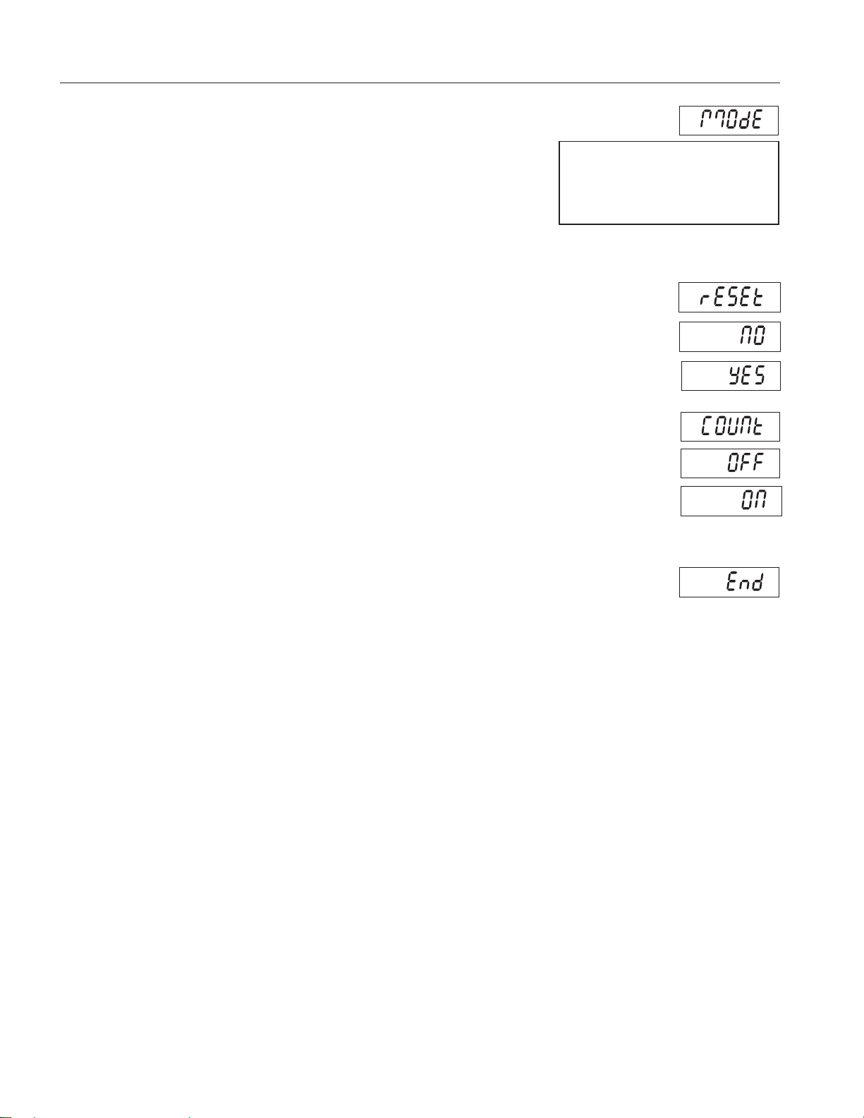
3.6 Mode Menu
EN-233000 Series Indicators
Enter this menu to activate the desired application
modes.
3.6.1 Reset
Set the Mode menu to the factory defaults.
No = not reset.
Yes = reset.
NOTE: If the Legal for trade menu item is set ON, the settings are not reset.
3.6.2 Parts Counting Mode
Set the status.
OFF = Disabled
ON = Enabled
Reset: No, Yes
Count: Off, On
End Mode Exit MODE menu
3.6.3 End Mode
Advance to the next menu.
Find Quality Products Online at: [email protected]
www.GlobalTestSupply.com
Page 34
EN-24 3000 Series Indicators
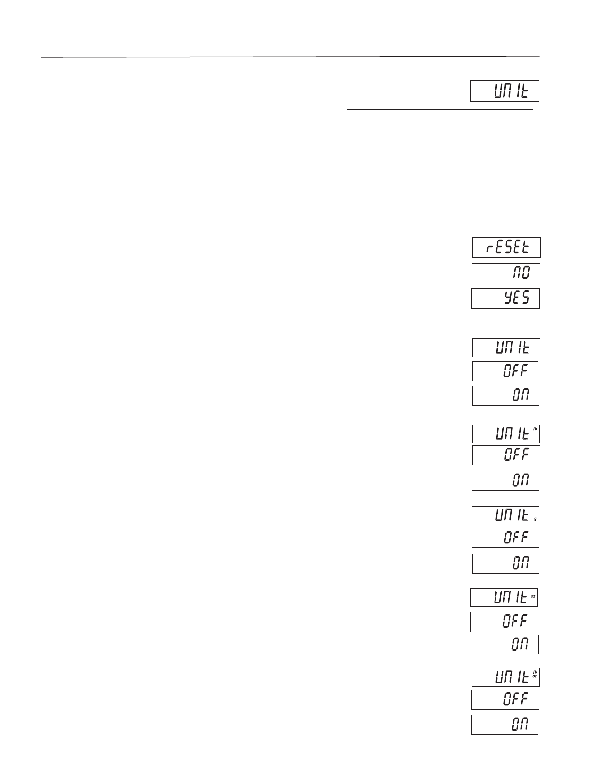
3.7 Unit Menu
Enter this menu to activate the desired units.
Default settings are bold.
Reset: No, Yes
Kilograms: Off, On
Pounds: Off, On
Grams: Off, On
Ounces: Off, On
Pounds:Ounces Off, On
End Unit Exit UNIT menu
3.7.1 Reset
Set the Unit menu to the factory defaults.
Settings:
NO = not reset.
YES = reset
If the Legal for Trade menu item is set ON, the settings are not reset.
3.7.2 Kilogram Unit
Set the status.
OFF = Disabled
ON = Enabled
3.7.3 Pound Unit
Set the status.
OFF = Disabled
ON = Enabled
3.7.4 Gram Unit
Set the status.
OFF = Disabled
ON = Enabled
3.7.5 Ounce Unit
Set the status.
OFF = Disabled
ON = Enabled
kg
3.7.6 Pound Ounce Unit
Set the status.
OFF = Disabled
ON = Enabled
Find Quality Products Online at: [email protected]
www.GlobalTestSupply.com
Page 35
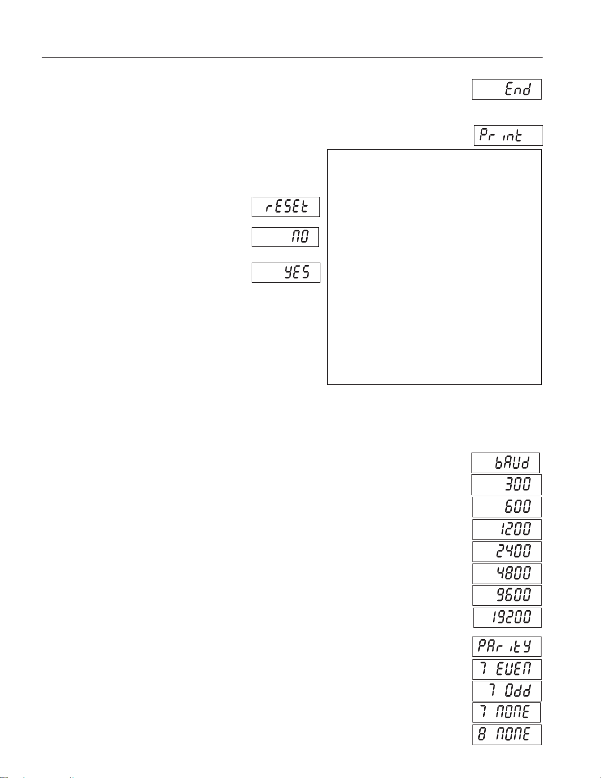
3.7.7 End Unit
Advance to the next menu.
3.8 Print Menu
EN-253000 Series Indicators
Enter this menu to define printing parameters. Default settings are bold.
3.8.1 Reset
Set the Print menu to factory defaults.
NO = not reset.
YES = reset.
NOTE: If the Legal for Trade menu item is set to ON, the following
settings are not reset: Stable, Auto Print
Reset No, Yes
Baud Rate: 300, 600, 1200, 2400, 4800,
9600, 19200
Parity: 7 Even, 7 Odd, 7 None, 8 None
Stop Bit 1 or 2
Handshake: Off, XON/XOFF
Stable Only Off, On
Auto Print Off,
On Stable (-> Load, Load and Zero),
Interval (-> 1…3600), Continuous
Content Gross (->Off, On)
Net (->Off, On)
Tare (->Off, On)
Unit (->Off, On)
End Print
Exit PRINT menu
3.8.2 Baud
Set the Baud rate.
300 = 300 bps
600 = 600 bps
1200 =1200 bps
2400 = 2400 bps
4800 = 4800 bps
9600 = 9600 bps
19200 = 19200 bps
3.8.3 Parity
Set the data bits and parity.
7 EVEN = 7 data bits, even parity.
7 Odd = 7 data bits, odd parity.
7 NONE = 7 data bits, no parity.
8 NONE = 8 data bits, no parity.
Find Quality Products Online at: [email protected]
www.GlobalTestSupply.com
Page 36
EN-26 3000 Series Indicators
3.8.4 Stop Bit
Set the number of stop bits.
1 = 1 stop bit.
2 = 2 stop bits.
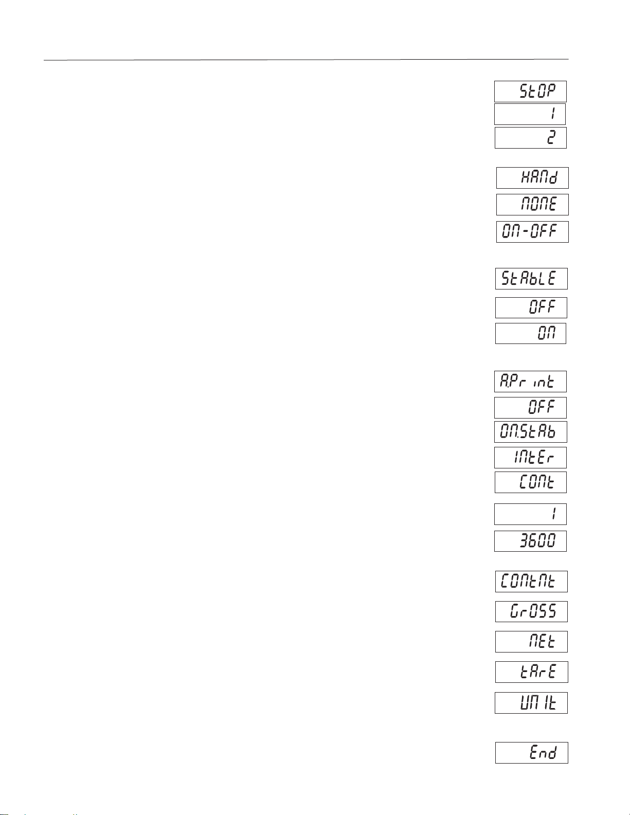
3.8.5 Handshake
Set the flow control method.
NONE = no handshaking.
ON-OFF = XON/XOFF software handshaking.
3.8.6 Print Stable Data Only
Set the print critera.
OFF = values are printed immediately.
ON = values are only printed when the stability criteria are met.
3.8.7 Auto Print
Set the automatic printing functionality.
OFF = disabled.
ON.StAb = printing occurs each time the stability criteria are met.
INtEr = printing occurs at the defined interval.
CONt = printing occurs continuosly.
When INtEr is selected, set the Print Interval.
1 to 3600 (seconds)
3.8.8 Content
Select the additional content of the printout.
GROSS OFF = Gross weight is not printed.
ON = Gross weight is printed.
NET OFF = Net weight is not printed.
ON = Net weight is printed.
TARE OFF = Tare weight is not printed.
ON = Tare weight is printed.
UNIT OFF = Unit is not printed.
ON = Unit weight is printed.
3.8.9 End Print
Advance to the next menu.
Find Quality Products Online at: [email protected]
www.GlobalTestSupply.com
Page 37
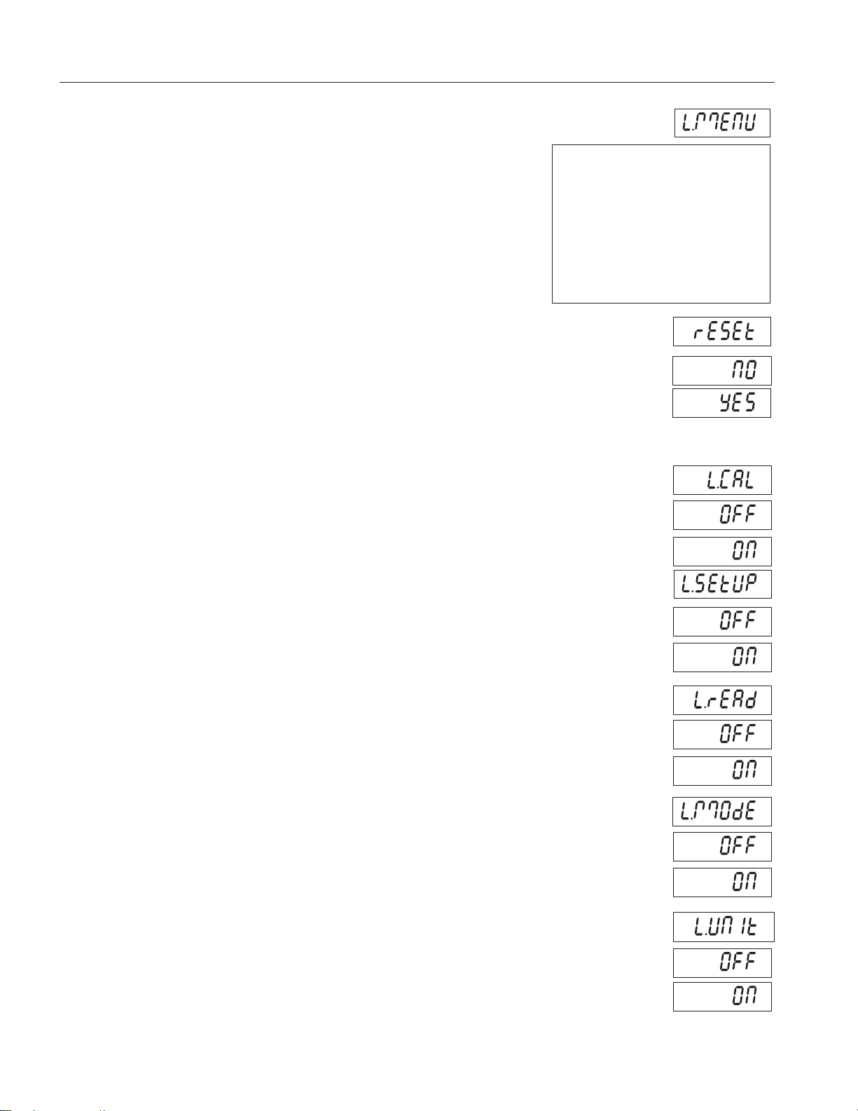
3.9 Menu Lock Menu
EN-273000 Series Indicators
Enter this menu. Default settings are bold.
3.9.1 Reset
Set the menu Lock menu to factory defaults.
NO = not reset.
YES = reset.
NOTE: Settings for LFT controlled menu items are not reset.
3.9.2 Lock Calibration
Set the status.
OFF = Calibration menu is not locked.
ON = Calibration menu is locked and hidden.
Reset: No, Yes
Lock Calibration Menu Off, On
Lock Setup Menu Off, On
Lock Readout Menu Off, On
Lock Mode Menu Off, On
Lock Unit Menu Off, On
Lock Print Menu Off, On
End Lock Menu
3.9.3 Lock Setup
Set the status.
OFF = Setup menu is not locked.
ON = Setup menu is locked and hidden.
3.9.4 Lock Readout
Set the status.
OFF = Readout menu is not locked.
ON = Readout menu is locked and hidden.
3.9.5 Lock Mode
Set the status.
OFF = Mode menu is not locked.
ON = Mode menu is locked and hidden.
3.9.6 Lock Unit
Set the status.
OFF = Unit menu is not locked.
ON = Unit menu is locked and hidden.
Find Quality Products Online at: [email protected]
www.GlobalTestSupply.com
Page 38
EN-28 3000 Series Indicators
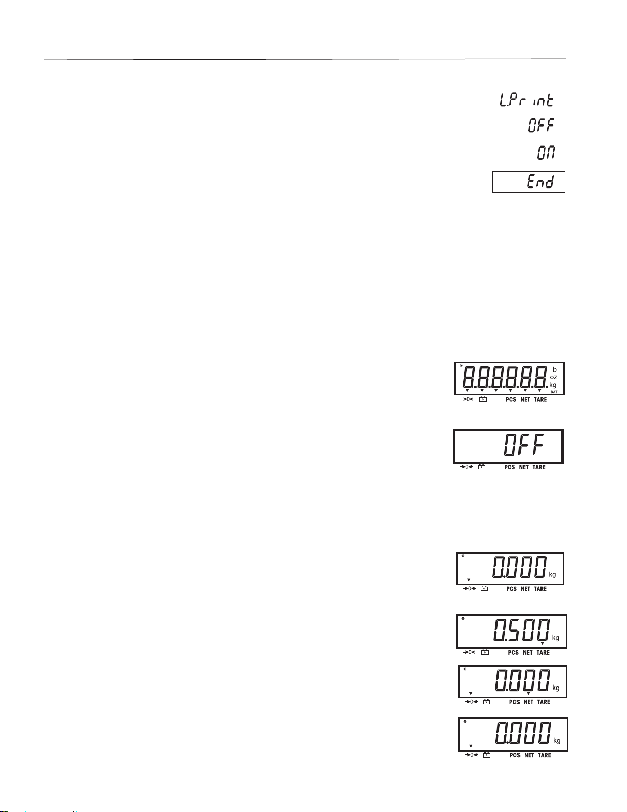
3.9.7 Lock Print
Set the status.
OFF = Print menu is not locked.
ON = Print menu is locked.
3.9.8 End Lock
Advance to the next menu.
3.10 Security Switch
A security switch is located on the Main PCB board. When the switch is set to the on position, user menu settings that were
locked in the Menu Lock can not be changed.
Open the housing as explained in Section 2.3.1. Set the position of security switch to ON as shown in Figure 1-3.
4 OPERATION
4.1 Turning Indicator On/Off
To turn the Indicator on, press the and hold the ON/ZERO
performs a display test, momentarily displays the software version, and then enters the active
weighing mode.
Off
button for 2 seconds. The Indicator
To turn the Indicator off, press and hold the ON/ZERO
Off
button until OFF is displayed.
4.2 Zero Operation
Zero can be set under the following conditions:
• Automatically at Power On (initial zero).
• Semi-automatically (manually) by pressing the ON/ZERO
• Semi-automatically by sending the Zero command (Z or alternate zero command).
Press the ON/ZERO
operation.
Off
button to zero the weight display. The scale must be stable to accept zero
Off
button.
4.3 Manual Tare
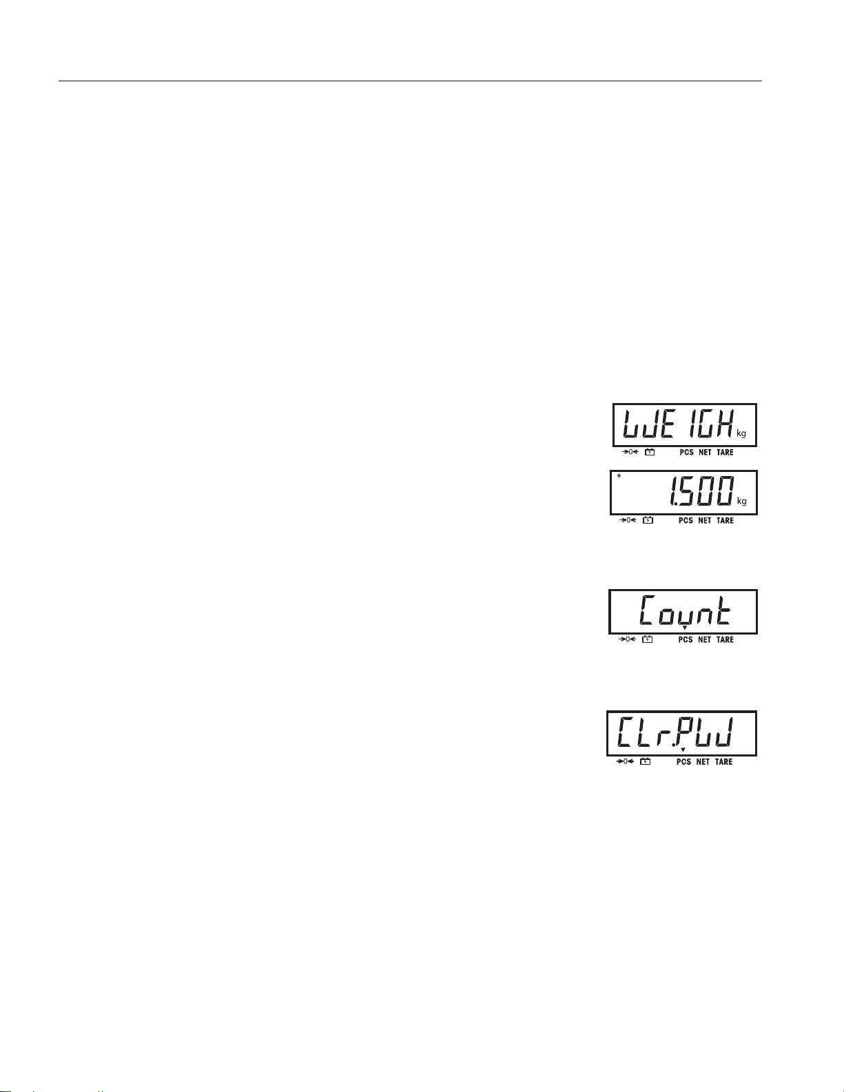
When weighing an item that must be held in a container, taring stores the container weight in
memory. Place the empty container on the scale (example 0.5 kg) and press the TARE button.
The display will show the net weight.
To clear the Tare value, empty the scale and press the TARE button. The display will show the
gross weight.
Find Quality Products Online at: [email protected]
www.GlobalTestSupply.com
Page 39
EN-293000 Series Indicators
4.4 Changing Units of Measure
Press and hold the PRINT
will be displayed (refer to Section 3.7).
Units
button until the desired measuring unit appears. Only measuring units enabled in the Unit Menu
4.5 Printing Data
Printing the displayed data to a printer or sending the data to a computer requires that the communication parameters in the Print
Menu are set (refer to Section 3.8).
Press the PRINT
must be Off).
Units
button to send the displayed data to the communication port (the Auto-Print Mode in Section 3.8 function
4.6 Application Modes
Only modes enabled in the mode menu will be displayed (refer to Section 3-6).
4.6.1 Weighing
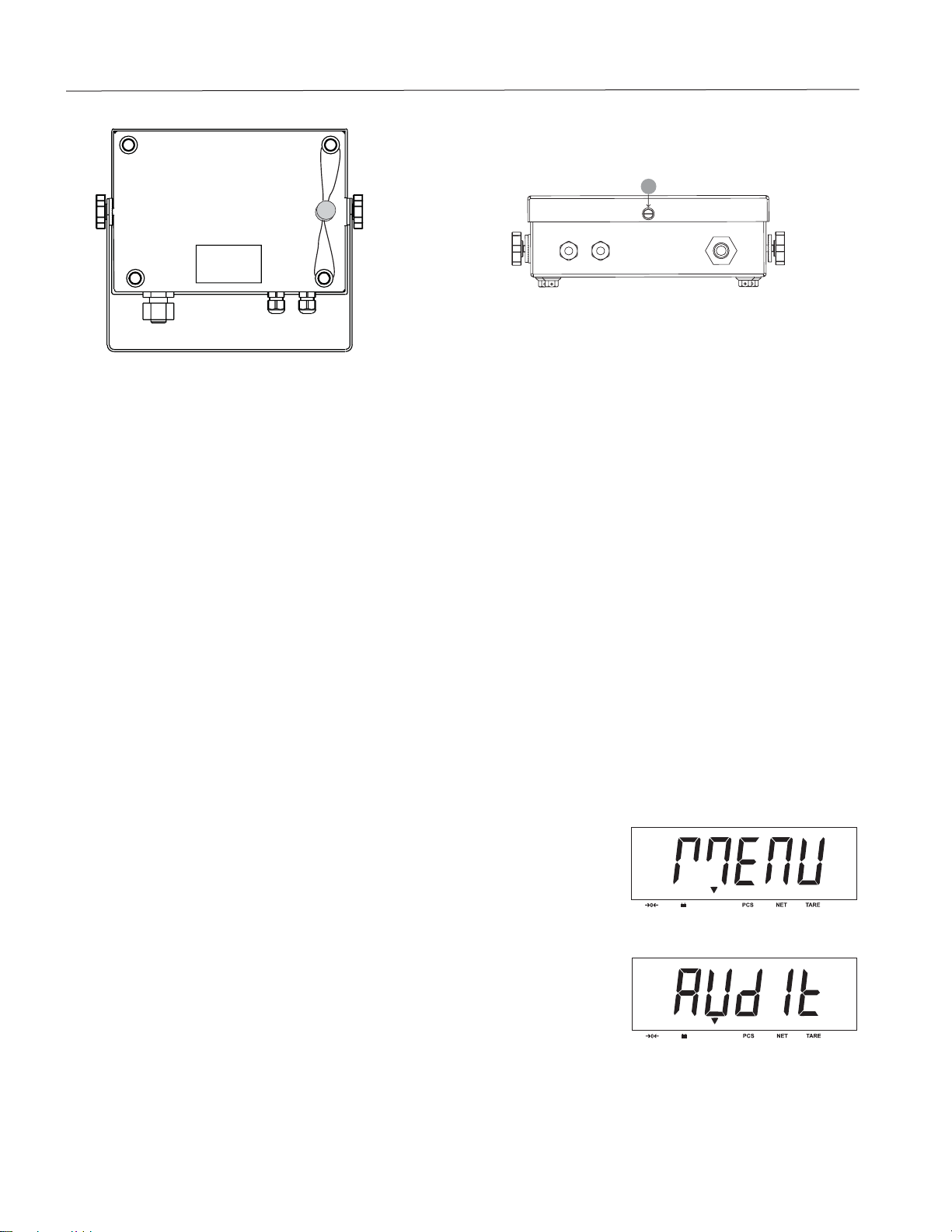
Place the item to be weighed on the scale. The illustration indicates a sample of 1.5 kg, Gross
weight.
Note: To return to the Weighing mode from the Parts Counting mode, press and hold the
button until WEIGH is displayed.
Mode
4.6.2 Parts Counting
Use this mode to count parts of uniform weight. The Indicator determines the quantity based on the
average weight of a single part. All parts must be uniform in weight for accurate measurements.
To enter the Parts Counting mode, press and hold the
Mode
button until Count is displayed.
Average Piece Weight (APW)
When the
NOTE: If no APW has been previously stored, the CLr.PW display is skipped and the display shows
PUt10Pcs.
Clearing a Stored APW
Press the Yes button to clear the stored APW.
Find Quality Products Online at: [email protected]
Mode
button is released, CLr.PW Pcs is displayed.
www.GlobalTestSupply.com
Page 40

EN-30 3000 Series Indicators
Recalling a Stored APW
Press the No button to recall the existing APW.
Mode
Press the FUNCTION
button to temporarily display the APW value.
Establishing the Average Piece Weight (APW)
The display shows Put10 Pcs.
Establishing a New APW
Press the No button to increment the sample size. Choices are 5, 10, 20, 50, 100 and 200.
To establish the APW, place the specified quantity of samples on the scale and press the Yes
button to capture the weight.
Begin Counting
Place the parts on the scale and read the count. If a container is used, be sure to tare the empty
container first.
Find Quality Products Online at: [email protected]
www.GlobalTestSupply.com
Page 41

EN-313000 Series Indicators
5 SERIAL COMMUNICATION
The T31P and T31XW Indicators include an RS232 serial communication interface.
The setup of RS232 operating parameters are more fully explained in Section 3.8. The physical hardware connection is
explained in in Section 2.2.
The interface enables display data to be sent to a computer or printer. A computer can be used to control some functions of
the indicator using the commands listed in Table 5-1.
5.1 Interface Commands
Communicate to the indicator using the command characters listed in Table 5-1.
TABLE 5-1. SERIAL INTERFACE COMMAND TABLE.
Command
Character
IP Immediate Print of displayed weight (stable or unstable).
P Print stable displayed weight (according to stability setting).
CP Continuous Print.
SP Print when stable.
xP Interval Print x = Print Interval (1-3600 sec)
Z Same as pressing Zero button
T Same as pressing Tare button
xT Download Tare value in grams (positive values only). Sending 0T clears tare (if allowed)
PU Print current unit: g, kg, lb, oz, lb:oz
xU Set scale to unit x: 1=g, 2=kg, 3=lb, 4=oz, 5=lb:oz
PV Version: print name, software revision and LFT ON (if LFT is set ON).
Esc R Global reset to reset all menu settings to the original factory defaults
NOTES:
• Commands sent to the Indicator must be terminated with a carriage return (CR) or carriage return-line feed (CRLF).
• Data output by the Indicator is always terminated with a carriage return-line feed (CRLF).
• The xT (preset tare) command is not available when LFT is set to ON.
Function
Find Quality Products Online at: [email protected]
www.GlobalTestSupply.com
Page 42

EN-32 3000 Series Indicators
5.2 Output Format
The default serial output format is shown below.
Field: Polarity Space Weight Space Unit Stability Legend CR LF
Length: 1 1 7 1 5 1 3 1 1
Definitions: Polarity, “-” sign if negative, blank if positive.
Weight, up to 6 numbers and 1 decimal, right justified, leading zero blanking.
Units, up to 5 characters.
Stability, “?” character is printed if not stable, blank if stable.
Legend, up to 3 characters: G = gross weight, NET = net weight, T = tare
Find Quality Products Online at: [email protected]
www.GlobalTestSupply.com
Page 43

EN-333000 Series Indicators
6. LEGAL FOR TRADE
When the indicator is used in trade or a legally controlled application it must be set up, verified and sealed in accordance with
local weights and measures regulations. It is the responsibility of the purchaser to ensure that all pertinent legal requirements are
met.
6.1 Settings
Before verification and sealing, perform the following steps:
1. Verify that the menu settings meet the local weights and measures regulations.
2. Perform a calibration.
3. Set Legal for Trade to ON in the Setup menu.
4. Exit the menu.
5. Disconnect power from the indicator and open the housing as explained in Section 2.3.1.
6. Set the position of the security switch to ON as shown in Section 1.2, Figure 1-3, Item 9.
7. Close the housing.
8. Reconnect power and turn the indicator on.
NOTE: For installations that employ the audit trail sealing method, steps 5 to 8 are not required. However, the security switch
may be set to ON to safeguard against unintentional changes to configuration and calibration settings.
NOTE: When Legal for Trade is set to ON and the security switch is set to ON, the following menu settings cannot be changed:
Span Calibration, Linearity Calibration, GEO, LFT, Calibration Unit, Capacity, Graduation, Power On Unit, Zero Range, Auto Zero
Tracking, Expanded Mode, Count Mode, Kilogram Unit, Pound Unit, Gram Unit, Ounce Unit, Pound Ounce Unit, Stable Only. To
enable editing of these menu settings, return the security switch to the off position and set LFT menu item to off.
6.2 Verification
The local weights and measures official or authorized service agent must perform the verification procedure. Please contact your
local weights and measures office for further details.
6.3 Sealing
6.3.1 Physical Seals
For jurisdictions that use the physical sealing method, the local weights and measures official or authorized service agent must
apply a security seal to prevent tampering with the settings. Refer to the illustrations below for sealing methods.
Figure 6-1. T31P Wire Seal Figure 6-2. T31P Paper Seal
Find Quality Products Online at: [email protected]
www.GlobalTestSupply.com
Page 44
EN-34 3000 Series Indicators
SEAL
SEAL
Figure 6-3. T31XW Wire Seal Figure 6-4. T31XW Paper Seal
6.3.2 Audit Trail Seal
For jurisdictions that use the audit trail sealing method, the local weights and measures official or authorized service agent must
record the current configuration and calibration event counter values at the time of sealing. These values will be compared to
values found during a future inspection.
NOTE: A change to an event counter value is equivalent to breaking a physical seal.
The audit trail uses two event counters to record changes to configuration and calibration settings.
The configuration event counter (CFG) will index by 1 when exiting the menu if one or more of the following settings
•
are changed Legal for Trade, Calibration Unit, Capacity, Graduation, Power On Unit, Zero Range, Auto Zero Tracking,
Expanded Mode, Count Mode, Kilogram Unit, Pound Unit, Gram Unit, Ounce Unit, Pound Ounce Unit, Stable Only. Note
that the counter only indexes once, even if several settings are changed. The configuration event counter values range
from CFG000 to CFG999. When the value reaches CFG999, the count starts over at CFG000.
The calibration event counter (CAL) will index by 1 when exiting the menu if a Span Calibration, Linearity Calibration
•
or GEO setting change is made. Note that the counter only indexes once, even if several settings are changed. The
calibration event counter values range from CAL000 to CAL999. When the value reaches CAL999, the count starts over
at CAL000.
The event counters can be viewed by pressing and holding the MENU button.
While the button is held, the display will show MENU followed by Audit.
CALIBRATION
MODE
Release the button when Audit is displayed to view the audit trail information.
CALIBRATION
MODE
Find Quality Products Online at: [email protected]
www.GlobalTestSupply.com
Page 45
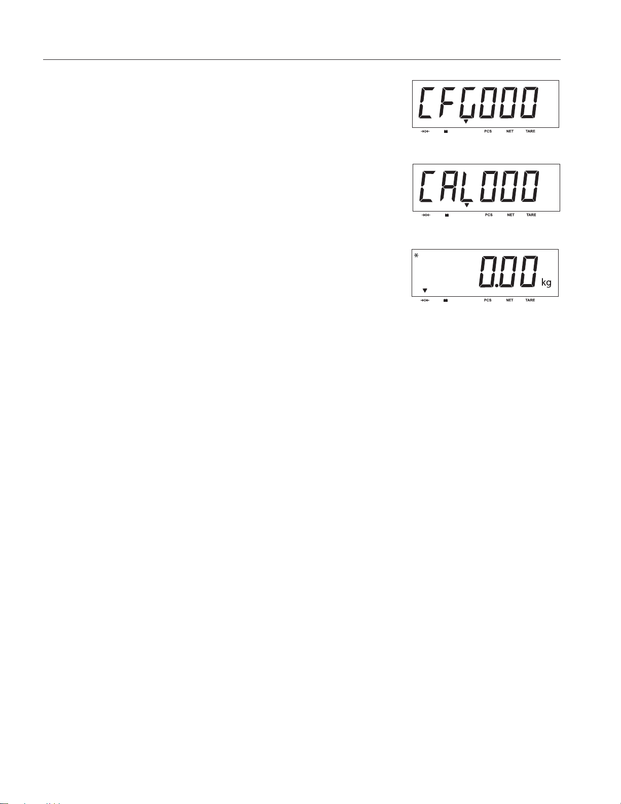
The audit trail information is displayed in the format CFGxxx and CALxxx.
Then the indicator returns to normal operation.
CALIBRATION
MODE
CALIBRATION
MODE
CALIBRATION
MODE
EN-353000 Series Indicators
Find Quality Products Online at: [email protected]
www.GlobalTestSupply.com
Page 46

EN-36 3000 Series Indicators
7 MAINTENANCE
CAUTION: DISCONNECT THE UNIT FROM THE POWER SUPPLY BEFORE CLEANING.
7.1 Model T31P Cleaning
• The housing may be cleaned with a cloth dampened with a mild detergent if necessary.
• Do not use solvents, chemicals, alcohol, ammonia or abrasives to clean the housing or control panel.
7.2 Model T31XW Cleaning
• Use approved cleaning solutions for the stainless-steel Indicator housing and rinse with water. Dry thoroughly.
• Do not use solvents, chemicals, alcohol, ammonia or abrasives to clean the control panel.
7.3 Troubleshooting
TABLE 7-1. TROUBLESHOOTING.
SYMPTOM PROBABLE CAUSE(s) REMEDY
Unit will not turn on. Power cord not plugged in or properly
connected.
Check power cord connections. Make sure
power cord is plugged in properly into the
power outlet.
Power outlet not supplying electricity.
Battery power used up. (T31P Only)
Other failure.
Cannot zero the Scale, or will not zero when
turned on.
Unable to calibrate. Lock Calibration Menu set to On.
Cannot display weight in desired weighing
unit.
Cannot change menu settings. Menu has been locked.
Battery indicator is flashing. (T31P Only) Battery discharged. Connect indicator to power and charge
Battery fails to charge fully. (T31P Only) Battery is defective. Have the battery replaced by an authorized
Error 7.0 Unstable weight reading when defining
Load on Scale exceeds allowable limits.
Load on Scale is not stable.
Load Cell damage.
Lock switch is “on”.
LFT menu set to On.
Incorrect value for calibration mass.
Unit not set to On. Enable unit in the Units Menu.
Lock switch set on.
reference weight.
Check power source.
Reconnect AC power to charge the battery.
Service required.
Remove load on Scale.
Wait for load to become stable.
Service required.
Set Lock Calibration Menu to Off.
Refer to Section 3.9 Menu Lock.
Set the Lock switch to Off.
Set LFT menu to Off.
Use correct calibration mass.
Refer to Section 3.7 in the Unit Menu.
Set selected menu to Off in the Lock Menu.
Lock Switch on the circuit board may
need to be set to the Off position.
Set the Lock switch to off.
battery.
Ohaus service dealer.
Unstable Error, check platform location.
Find Quality Products Online at: [email protected]
www.GlobalTestSupply.com
Page 47

EN-373000 Series Indicators
TABLE 7-1. TROUBLESHOOTING (Cont.).
SYMPTOM PROBABLE CAUSE(s) REMEDY
Error 8.1 Weight reading exceeds Power On Zero limit. Remove load from scale. Recalibrate scale.
Error 8.2 Weight reading below Power On Zero limit. Add load to scale. Recalibrate scale.
Error 8.3 Weight reading exceeds Overload limit. Reduce load on scale.
Error 8.4 Weight reading below Underload limit. Add load to scale. Recalibrate scale.
Err 9.0 Internal fault Service required.
Err 9.5 Calibration data not present. Calibrate scale.
Err 53 EEPROM data incorrect. Service required.
CAL E Calibration Error. Calibration value outside
allowable limits.
LOW.rEF The average piece weight of the parts is small
(warning).
REF.WT Err The average piece weight of the parts is too
small.
Repeat calibration using correct calibration
weights.
Use parts with average piece weight greater
than or equal to 1 division.
Use parts with a average piece weight
greater than or equal to 0.1 division.
7.4 Service Information
Find Quality Products Online at: [email protected]
www.GlobalTestSupply.com
Page 48

EN-38 3000 Series Indicators
8. TECHNICAL DATA
8.1 Specifications
Materials
T31XW Housing: stainless steel
T31P Housing: ABS plastic
Keypad: polyester
Feet: Rubber
Display Window: Polycarbonate
Ambient conditions
The technical data is valid under the following ambient conditions:
Ambient temperature: -10°C to 40°C / 14°F to104°F
Relative humidity: Maximum relative humidity 80% for temperatures up to 31°C decreasing linearly to 50%
relative humidity at 40°C.
Altitude: up to 2000m
Operability is assured at ambient temperatures between -10°C. and 40°C.
TABLE 8-1. SPECIFICATIONS
Indicator T31P T31XW
Capacity Range 5 to 20000 kg or lb
Maximum Displayed Resolution 1:20,000
Type Approved Resolution 1:6,000
Minimum Average Piece Weight
(APW)
Weighing Units kg, lb, g, oz, lb:oz
Functions Weighing, Parts Counting
Display 1 in./2.5 cm digit height, 6-digit, 7-segment
1.5 in./3.8 cm high x 4.9 in./12.5 cm wide backlit LCD
Backlight White LED
Keypad 4-button mechanical switches 4-button membrane switch
Ingress Protection --- IP66
Load Cell Excitation Voltage 5V DC
Load Cell Drive Up to 4 x 350 ohm Load Cells
Load Cell Input Sensitivity Up to 3 mV/V
Stabilization Time Within 2 Seconds
Auto-zero Tracking Off, 0.5, 1 or 3 Divisions
Zeroing Range 0%, 2% or 100% of Capacity
Span Calibration 5 kg or 5 lb to 100% Capacity
Interface RS232
Overall Dimensions (W x D x H)
(in/mm)
Net Weight (lb/kg) 3.6 / 1.6 6.6 / 2.9
Shipping Weight (lb/kg) 5.7 / 2.6 8.8 / 4.0
Operating Temperature Range -10°C to 40°C/14°F to 104°F
Power 9 - 12VDC, 0.5A, AC Adapter with Internal rechargeable, Sealed Lead-Acid
Find Quality Products Online at: [email protected]
8.2 x 2.8 x 6.5 / 210 x 71 x 168 8.3 x 2.8 x 5.8 / 212 x 71 x 149
Battery (100-hour typical life) (T31P)
www.GlobalTestSupply.com
100-240 VAC / 50-60 Hz, Internal Power Supply (T31XW)
1d
Page 49
8.2 Accessories
EN-393000 Series Indicators
TABLE 8-2. ACCESSORIES.
DESCRIPTION PART NUMBER
Column Mount Kit, 35 cm painted steel 80251743
Column Mount Kit, 70 cm painted steel 80251744
Column Mount Kit, 35 cm stainless steel 80251745
Column Mount Kit, 70 cm stainless steel 80251746
Wall Mount Kit, T31P 80251747
Wall Mount Kit, T31XW 80251748
Interface Cable/PC 25-pin, T31P 80500524
Interface Cable/PC 9-pin, T31P 80500525
Interface Cable/PC 9-pin, T31XW 80500552
Interface Cable/PC 25-pin, T31XW 80500553
Find Quality Products Online at: [email protected]
www.GlobalTestSupply.com
Page 50
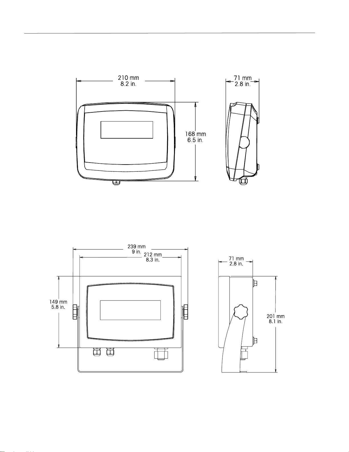
EN-40 3000 Series Indicators
8.3 Drawings and Dimensions
Figure 8-1. T31P Indicator Overall Dimensions.
Figure 8-2. T31XW Indicator Overall Dimensions with Mounting Bracket.
Find Quality Products Online at: [email protected]
www.GlobalTestSupply.com
Page 51
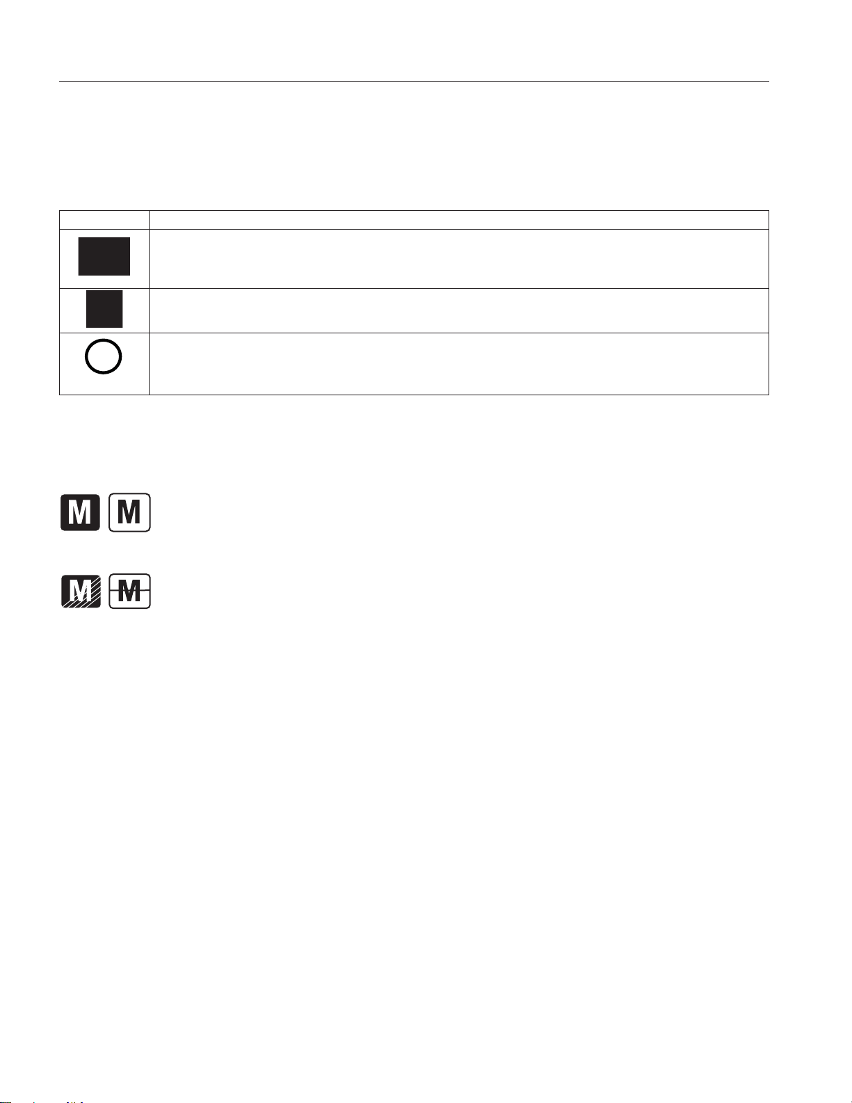
8.4 Compliance
Compliance
Compliance to the following standards is indicated by the corresponding mark on the product.
Marking Standard
This product conforms to the EMC directive 2004/108/EC, the Low Voltage Directive 2006/95/EC and the
Non-automatic Weighing Instruments Directive 2009/23/EC. The complete Declaration of Conformity is
AS/NZS4251.1 Emission, AS/NZS4252.1 Immunity
U
®
L
LISTE D
US
UL60950-1: 2003
C
EC Emissions Note
This device complies with EN55011/CISPR 11 Class B Group 1.
EN-413000 Series Indicators
Important notice for verified weighing instruments
Weighing Instruments verified at the place of manufacture bear one of the preceding marks on the packing
label and the green ‘M’ (metrology) sticker on the descriptive data plate.
They may be put into service immediately.
Weighing Instruments to be verified in two stages have no green ‘M’ (metrology) on the descriptive data
plate and bear one of the preceding identification marks on the packing label. The second stage of the initial
verification must be carried out by an authorized and certified service organization established within the
European Community or by the National Notified Body.
The first stage of the initial verification has been carried out at the manufacturer’s work. It comprises all tests
according to the adopted European Standard EN 45501:1992, paragraph 8.2.2.
If national regulations limit the validity period of the verification, the user of the weighing instrument must
strictly observe the re-verification period and inform the respective Weights and Measures authority.
Find Quality Products Online at: [email protected]
www.GlobalTestSupply.com
Page 52

EN-42 3000 Series Indicators
Disposal
In conformance with the European Directive 2002/96/EC on Waste Electrical and Electronic Equipment
(WEEE) this device may not be disposed of in domestic waste. This also applies to countries outside the EU,
per their specific requirements.
The Batteries Directive 2006/66/EC introduces new requirements from September 2008 on removability of
batteries from waste equipment in EU Member States. To comply with this Directive, this device has been
designed for safe removal of the batteries at end-of-life by a waste treatment facility.
Please dispose of this product in accordance with local regulations at the collecting point specified for
electrical and electronic equipment.
If you have any questions, please contact the responsible authority or the distributor from which you
purchased this device.
Should this device be passed on to other parties (for private or professional use), the content of this regulation
must also be related.
for WEEE.
Thank you for your contribution to environmental protection.
FCC Note
This equipment has been tested and found to comply with the limits for a Class A digital device, pursuant to Part 15 of the FCC
Rules. These limits are designed to provide reasonable protection against harmful interference when the equipment is operated
in a commercial environment. This equipment generates, uses, and can radiate radio frequency energy and, if not installed
and used in accordance with the instruction manual, may cause harmful interference to radio communications. Operation of
this equipment in a residential area is likely to cause harmful interference in which case the user will be required to correct the
interference at his own expense.
Industry Canada Note
This Class A digital apparatus complies with Canadian ICES-003.
ISO 9001 Registration
In 1994, Ohaus Corporation, USA, was awarded a certificate of registration to ISO 9001 by Bureau Veritus Quality International
(BVQI), confirming that the Ohaus quality management system is compliant with the ISO 9001 standard’s requirements. On May
21, 2009, Ohaus Corporation, USA, was re-registered to the ISO 9001:2008 standard.
Find Quality Products Online at: [email protected]
www.GlobalTestSupply.com
Page 53

LIMITED WARRANTY
Ohaus products are warranted against defects in materials and workmanship from the date of delivery through the duration of
the warranty period. During the warranty period Ohaus will repair, or, at its option, replace any component(s) that proves to be
defective at no charge, provided that the product is returned, freight prepaid, to Ohaus.
This warranty does not apply if the product has been damaged by accident or misuse, exposed to radioactive or corrosive
materials, has foreign material penetrating to the inside of the product, or as a result of service or modification by other than
Ohaus. In lieu of a properly returned warranty registration card, the warranty period shall begin on the date of shipment to the
authorized dealer. No other express or implied warranty is given by Ohaus Corporation. Ohaus Corporation shall not be liable
for any consequential damages.
Find Quality Products Online at: [email protected]
www.GlobalTestSupply.com
 Loading...