

Page 1
Ohaus CorporationOhaus Corporation
Ohaus Corporation
Ohaus CorporationOhaus Corporation
29 Hanover Road
Florham Park, NJ
07932-0900
CD Indicators
INSTRUCTION MANUAL
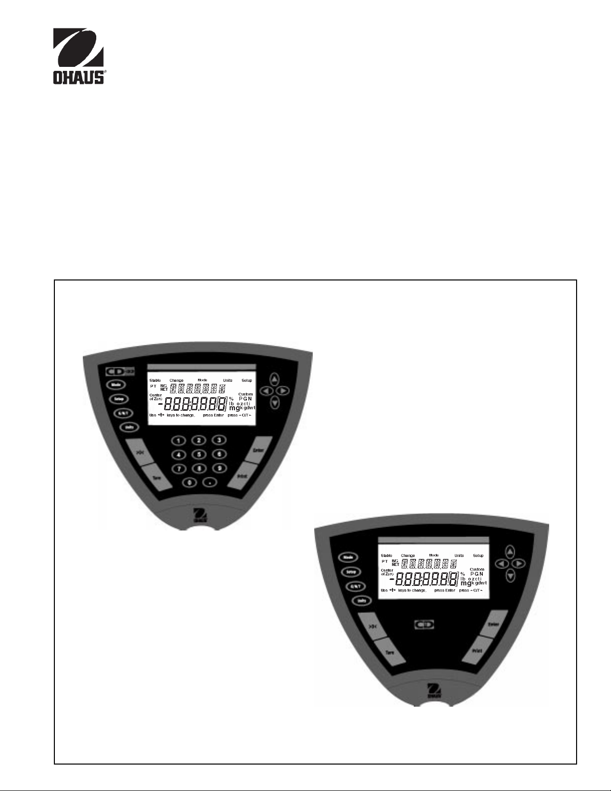
Models CD-31 and CD-33 Indicators
1
Page 2
CD Indicators
Ohaus Corporation, 29 Hanover Road, Florham Park, New Jersey, 07932, USA
Declaration of Conformity We, Ohaus Corporation, declare under our sole responsibility that the instrument models listed below marked with
“CE” - are in conformity with the directives and standards mentioned.
Konformitätserkärung Wir, die Ohaus Corporation, erklären in alleiniger Verantwortung, dass die untenstehenden Waagentypen, instrument
mit “CE” - mit den genannten Richtlinien und Normen übereinstimmen.
Déclaration de conformité Nous, Ohaus Corporation, déclarons sous notre seule responsabilité, que les types de instrument ci-dessous cité
- munis de la mention «CE» - sont conformes aux directives et aux normes mentionnées ci-après.
Declaración de Conformidad Nostras, Ohaus Corporation, declaramos bajo responsabilidad exclusiva que los modelos de instrumento
indicados a continuación - con el distintivo ,CE’ - están conformes con las directivas y normas citadas.
Dichiarazione di conformità Noi, Ohaus Corporation, U.S.A, dichiariamo sotto nostra unica responsabilità, che i tipi di strumento specificati di
seguito - contrassegnati con la marcatura “CE” - sono conformi alle direttive e norme citate.
Instrument Type/Waagentyp/Type de instrument/Modelo de instrumento/Tipo di strumento CD-31/CD-33 Indicators
Marked with: Directive Standard
Gekennzeichnet mit: Richtlinie Norm
Munis de la mention: Directive Norme
Con el distintivo: Directiva Norma
Contrassegnati con la Direttiva Norma
Marcatura:
EU 73/23 Low Voltage
EU 73/23 Niederspannung
EU 73/23 Basse tension
EU 73/23 Baja tensión
EU 73/23 Bassa tensione
EU 89/336, 92/31, 93/68
Electromagnetic compatibility
EU 89/336, 92/31, 93/68
Elektromagnetische Verträglichkeit
EU 89/336, 92/31, 93/68
Compatibilité électromagnétique
EU 89/336, 92/31, 93/68
Compatibilidad electromagnética
EU 89/336, 92/31, 93/68
Compatibilità elettromagnetica
IEC1010-1 & EN60950:1992 Safety Regulations
IEC1010-1 & EN60950:1992 Sicherheitsbestimmungen
IEC1010-1 & EN60950:1992 Consignes de sécurité
IEC1010-1 & EN60950:1992 Disposiciones sobre seguridad
IEC1010-1 & EN60950:1992 Prescrizioni . di sicurezza
EN55022:1987 Emissions
EN50082-1:1992 Immunity
NOTE: The displayed value may be adversely affected under
extreme electromagnetic influences, eg. when using a radio unit in the
immediate vicinity of the device. Once the interference has been
rectified, the product can once again be used for its intended purpose.
EN55022:1987 Funkstörungen
EN50082-1:1992 Immunität
Hinweis: Unter extremen elektromagnetischen Einflüssen z.B. bei
Betreiben eines Funkgerätes in unmittelbarer Nähe des Gerätes kann
eine Beeinflussung des Anzeigewertes verusacht werden. Nach Ende
des Störeinflusses ist das Produkt wieder bestimmungsgemäss
benutzbar.
EN55022:Emissions parasites
EN50082-1:1992 Immunité
Remarque: Dans des conditions d'influences électromagnètiques
extrêmes, par exemple en cas d'exploitation d'un appareil radio à
proximité immédiate de l'appareil la valeur d'affichage risque d'être
influencée. Une fois que l'influence parasite est terminée, le produit
peut être de nouveau utilisé de manière conforme aux prescriptions.
EN55022:1987 Radiointerferencias
EN50082-1:1992 Inmunidad
Nota: Bajo influencias electromagnèticas extremas, p.ej. cuando
funciona una radio en las inmediaciones del aparato, se pueden
alterar los valores del display. Cuando concluye el efecto perturbador,
el producto puede ser utilizado de nuevo, de acuerdo con lo
estipulado.
EN55022:1987 Radiointerferenze
EN50082-1:1992 Immunità
Nota: ll valore visualizzato può essere influenzato negativamente dalla
presenza di forti interferenze elettromagnetiche, per esempio quando
viene usata una radio in prossimità della bilancia. Eliminata la fonte
dell'interferenza, il prodotto può essere nuovamente utilizzato per le
funzioni cui è preposto.
2
Page 3

CD Indicators
NOTE: THIS EQUIPMENT HAS BEEN TESTED AND FOUND T O COMPL Y WITH THE LIMITS FOR A CLASS A DIGITAL
DEVICE, PURSUANT TO PART 15 OF THE FCC R ULES.
THESE LIMITS ARE DESIGNED T O PRO VIDE REASONABLE PRO TECTION AGAINST HARMFUL INTERFERENCE
WHEN THE EQUIPMENT IS OPERATED IN A COMMERCIAL ENVIRONMENT. THIS EQUIPMENT GENERATES,
USES, AND CAN RADIATE RADIO FREQ UENCY ENERGY AND , IF NO T INSTALLED AND USED IN ACCORDANCE
WITH THE INSTR UCTION MANUAL, MAY CAUSE HARMFUL INTERFERENCE TO RADIO COMMUNICATIONS. OPERATION OF THIS EQUIPMENT IN A RESIDENTIAL AREA IS LIKELY TO CAUSE HARMFUL INTERFERENCE IN
WHICH CASE THE USER WILL BE REQUIRED TO CORRECT THE INTERFERENCE AT HIS OWN EXPENSE.
THIS DIGITAL APPARATUS DOES NOT EXCEED THE CLASS A LIMITS FOR RADIO NOISE EMISSIONS FROM
DIGIT AL APPARA TUS AS SET OUT IN THE INTERFERENCE-CA USING EQUIPMENT STANDARD ENTITLED “DIGIT AL APPARA TUS”, ICES-003 OF THE DEPARTMENT OF COMMUNICATIONS .
CET APPAREIL NUMERIQUE RESPECTE LES LIMITES DE BRUITS RADIOELECTRIQUES APPLICABLES AUX
APPAREILS NUMERIQUES DE CLASSE A PRESCRITES DANS LA NORME SUR LE MATERIEL BROUILLEUR :
“APP AREILS NUMERIQUES”, NMB-003 EDICTEE PAR LE MINISTRE DES COMMUNICA TIONS.
Unauthorized changes or modifications to this equipment are not permitted.
Before plugging in the Indicator , make sure that the
voltage of the power adapter and plug match.
3
Page 4

CD Indicators
TABLE OF CONTENTS
OV ERVIEW OF CONTR OLS ........................................................................................................................ 1
OVER VIEW OF DISPLA Y INDICATORS ...................................................................................................... 2
1. GETTING TO KNOW Y OUR INDICA TOR ............................................................................................................ 3
1.1 Introduction3
2. INST ALLA TION ................................................................................................................................................... 3
2.1 Unpacking and Checking .................................................................................................................................... 3
2.2 Selecting the Location ........................................................................................................................................ 3
2.3 Connecting the Indicator to a Scale base ........................................................................................................... 4
2.4 Connecting the RS232 Interface .........................................................................................................................4
2.4.1 Hardware .................................................................................................................................................. 4
2.5 Connecting Power ............................................................................................................................................... 5
2.5.1 Cautionary Notes ...................................................................................................................................... 5
2.5.2 Turning On the Indicator ............................................................................................................................ 5
2.5.3 Po wer ON/OFF ......................................................................................................................................... 5
2.6 Scale Base Setup............................................................................................................................................... 6
3. SETTING UP Y OUR INDICATOR...................................................................................................................... 10
3.1 Setting Time and Date ...................................................................................................................................... 10
3.2 Readout ..................................................................................................................................................... 11
3.3 Good Manufacturing Practices (GMP) Data...................................................................................................... 13
3.4 Good Manufacturing Practices (GMP) Set........................................................................................................ 14
3.5 Print ..................................................................................................................................................... 15
3.6 RS232 ..................................................................................................................................................... 16
3.7 Legal for T rade (LFT)......................................................................................................................................... 17
3.8 Mode ..................................................................................................................................................... 18
3.9 Units ..................................................................................................................................................... 19
3.10 Global ..................................................................................................................................................... 19
3.11 Custom Unit ............................................................................................................................................... 21
3.12 Menu Lock-Out Protection .......................................................................................................................... 22
4
Page 5

CD Indicators
TABLE OF CONTENTS (Cont.)
4. OPERATING YOUR INDICATOR ....................................................................................................................... 23
4.1 Calibration23
4.1.1 Span Calibration ..................................................................................................................................... 2 4
4.1.2 User Calibration ...................................................................................................................................... 25
4.1.3 Linearity Calibration ................................................................................................................................ 26
4.1.4 Calibration Test ....................................................................................................................................... 37
4.1.5 Calibration GMP Printout ........................................................................................................................ 28
4.2 Weighing 29
4.2.1 Manual Taring.......................................................................................................................................... 2 9
4.2.2 Preset Taring ........................................................................................................................................... 30
4.3 Percent Weighing .............................................................................................................................................. 3 1
4.4 Parts Counting.................................................................................................................................................. 32
4.5 Animal Weighing ............................................................................................................................................... 33
4.6 Checkweigh34
4.7 Printing Data............................................................................................................................................... 35
4.7.1 RS232 Commands.................................................................................................................................. 35
4.7.2 Output Formats....................................................................................................................................... 35
5. CARE AND MAINTENANCE ............................................................................................................................ 38
5.1 T roub leshooting................................................................................................................................................. 38
5.2 Error Codes List................................................................................................................................................ 3 9
5.3 Service Information......................................................................................................... .................................. 40
5.4 Replacement Parts ........................................................................................................................................... 40
5.5 Accessories4 0
5.6 T echnical Data .................................................................................................................................................. 40
5
Page 6
CD Indicators
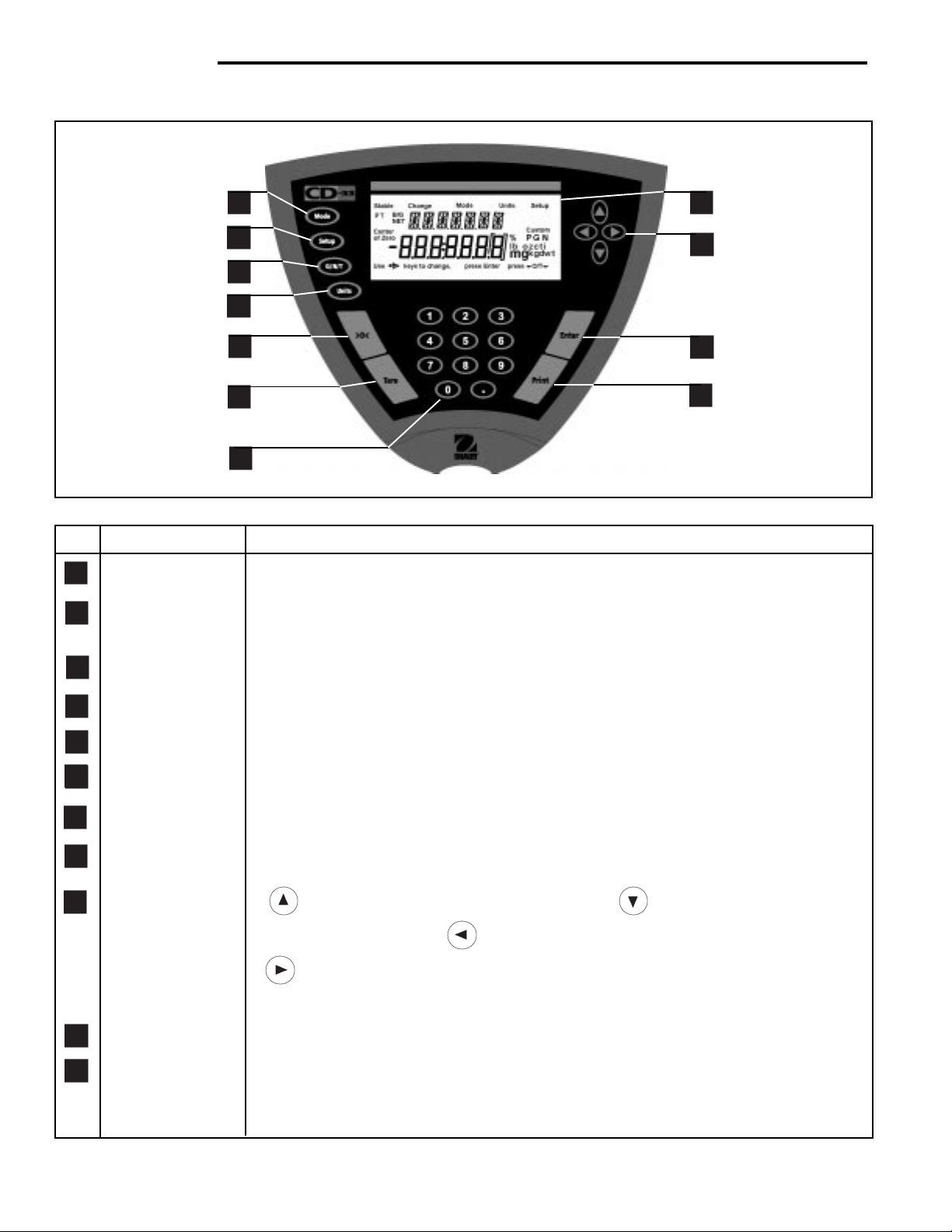
OVERVIEW OF CONTROLS
1
2
3
4
5
6
7
No. Designation Function
1 Mode button Selects standard weighing, percent, parts counting, check weighing and animal weighing.
2 Setup button Selects various submenus: scale, calibration, date, time, readout, GMP data, GMP set,
print, RS232, LFT, mode, units, global, custom.
8
9
10
11
3 G/N/T button Selects Gross, Net or Tare weights.
4 Units button Selects weighing units: grams, kilogr ams, pounds, custom, parts counting, percent.
5 >0< button When pressed, zero's scale.
6 T are button When pressed, performs tare function.
7 Numeric keypad 0 to 9 keys and decimal point keypad, used to enter numerical data on Model CD-33.
8 Display LCD display indicates weight, modes and setup information.
9 Arrow buttons when pressed, travels up through submenus. button when pressed, travels
down through submenus. button when pressed, travels to the left through menus.
button when pressed, travels to the right through menus. Arrow buttons are also
used to enter numerical data on Model CD-31.
10 Enter button When in menus, selects item on display. Also used to turn power on when in sleep mode.
11 Print button When pressed, prints data.
6
Page 7
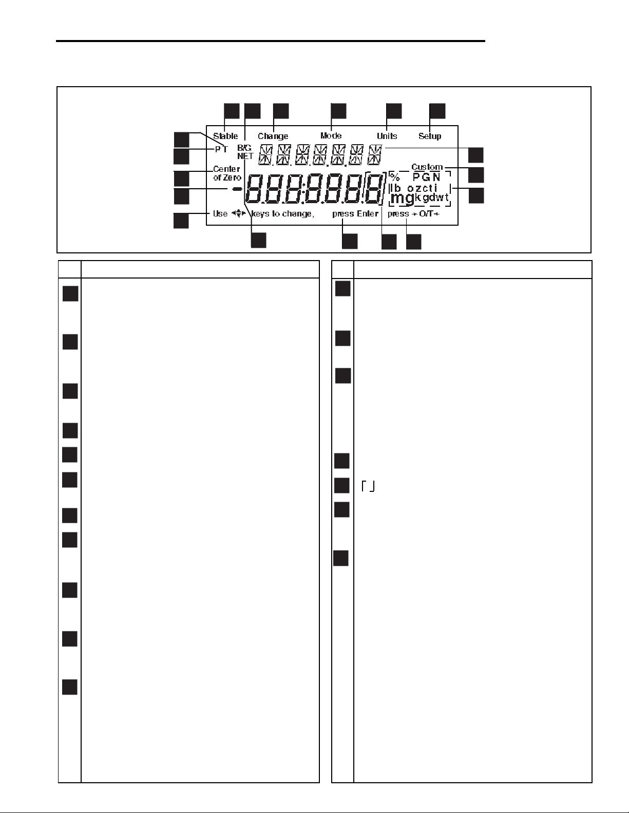
OVERVIEW OF DISPLAY INDICATORS
CD Indicators
6
5
4
3
2
1
No. Function
1 Use (Pointer Group) keys to c hange - used to
prompt the user while navigating through the
menu system.
2 Standard (7) segment numeric characters. Seven
characters are available and are used for displaying
weight values.
3 Center of Zero - Indicates display is within ± 1/4d
of zero.
4 P - Displayed if preset tare weight.
8
7
9
1718
No. Function
12 (British Flag) - Are (14) segment alpha numeric
13 Custom - The user can input a factor to meet
14 Symbols for weighing modes, include:
10
16
characters. Seven characters are used to present
features and functions.
unique unit measure applications.
g - Grams.
kg - Kilograms.
lb - Pounds.
PC - Parts counting.
% - Percent w eighing.
11
12
13
14
15
5 T - Displayed with tare weight.
6 Stable - Indicates that the measured value has
become stable.
7 B/G - Displayed with gross weight.
8 Change - Is displayed together with Mode, Units
or Setup signifying that a change to balance
settings is being performed.
9 Mode - Is displayed when the Mode button is
pressed. Allows the user to know what area of
the balance menu is being addressed.
10 Units - Is displayed when the Units button is
pressed. Allows the user to know what area of the
balance menu is being addressed.
11 Setup - Is displayed when the Setup button is
pressed. Allows the user to know what area of the
balance menu is being addressed.
15 Press >O/T< -This symbol is not used.
16 - This sysmbol is not used.
17 Press Enter - Used as a prompt to the user to
press the Enter button. The menu item displa y ed
is accepted/selected.
18 NET - Displayed with net weight.
7
Page 8

CD Indicators
1. GETTING TO KNOW YOUR INDICATOR
1.1Introduction
Thank you for deciding to purchase a CD-31/CD-33 Indicator from Ohaus. It offers a high level of operating convenience and useful functions to make accurate measurements. A unique LCD panel has a large 7 digit, 7 segment
display which indicates the weight value of an item being measured and a 7 digit British Flag display (14 segments)
which spells out items selected in the submenus. In addition, the display contains English text to indicate the status
of the scale. Arrow indicators in the display provide a prompt as to what panel buttons are to be pressed to initiate a
change. The maximum capacity which can be displa y ed on the Indicator is 199,999 pounds or kilograms. The
Indicator can be table mounted, wall mounted, or tower mounted.
The Indicator is designed to operate with a wide variety of Ohaus scale bases and other scale bases that contain up
to 4-350 ohm load cells.
Behind your instrument stands OHAUS , a leading manuf acturer of precision Indicators, Scales and Balances. An
Aftermarket Department with trained instrument technicians is dedicated to provide you with the fastest service
possible in the event y our instrument requires servicing. OHA US also has a Customer Service Department to answer
any inquiries regarding applications and accessories.
To ensure you make full use of the possibilities offered b y your CD-31/CD-33 Indicator , please read the manual
completely before installation and operation.
2. INSTALLATION
2.1 Unpacking and Checking
Open the package and remov e the instrument and the accessories. Chec k the completeness of the delivery. The
following accessories are part of the standard equipment of your new Indicator .
• Remove packing material from the instrument.
• Check the instrument for transport damage. Immediately inform your Ohaus dealer if you ha v e complaints or
parts are missing. Your Indicator package should contain:
• Indicator CD-31 or CD-33
• AC Adapter , 9 V dc, 500 ma output
• Instruction Manual
• Warranty card
• Capacity label
• Plain screwdriver
• Lead & wire calibration seal
• Cover plate and (2) screws
• Store all parts of the packaging. This packaging guarantees the best possib le protection f or the transport of your
instrument.
2.2 Selecting the Location
The Indicator should be used in an environment which is free from corrosives, vibration, and temperature or humidity
extremes. These factors will aff ect displa yed w eight readings . Scale bases used with the Indicator should be located
on a stable lev el surf ace and k ept a w a y from vibr ating sources such as large machinery. Maximum accuracy will be
achieved when the area is clean and vibration free.
8
Page 9
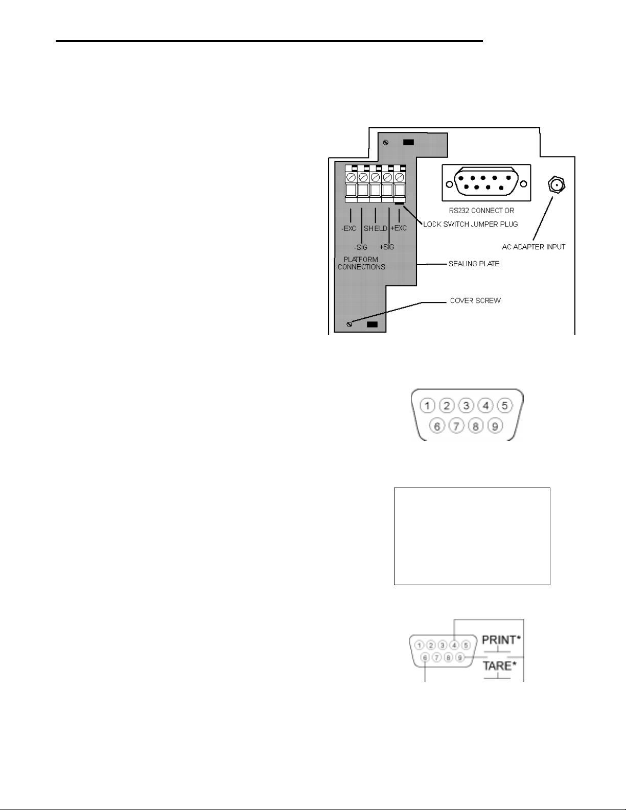
2. 3 Connecting the Indicator to a Scale Base
• Turn the Indicator over .
NOTE:Check the wiring instructions of your scale base.
• The Terminal Block located at the left side of the
access area is used to connect a scale base using
a 4-wire cable and ground. If a 6-wire cable is
supplied with the scale base, tie the +SENSE and
+EXC leads together and connect to the +EXC
connector. Tie the -SENSE and -EXC leads together
and connect it to the -EXC connector on the Indicator.
• Connect the wires to the T erminal Block. Tighten all
screws securely.
• To pro vide a strain relief , dress the wire cable from
the scale base in the channel provided on the
bottom of the indicator.
CD Indicators
• If the Indicator is not used in a legal for trade
application, install the sealing plate at the bottom of
the Indicator and secure with two screws as shown
on the illustration.
2.4 Connecting the RS232 Interface
CD-31/CD-33 Indicators are equipped with a standard
TM
IBM
compatible, bi-directional RS232 interface for
communication with printers and computers. When the
Indicator is connected directly to a printer or Programmable Logic Controller (PLC), displayed data can be
recorded at any time by simply pressing the PRINT
button.
Connecting the Indicator to a computer or PLC enables
you to operate several functions of the Indicator from the
computer, as well as receiv e data such as displa y ed
weight, weighing mode, stability status, etc.
2.4.1Hardware
A 9-pin “D” connector is located inside of the recessed
area at the bottom of the indicator. Pin connections are
shown in the adjacent illustration.
Connect an Ohaus RS232 cable to the Indicator. Refer to
paragraph 5.5 Accessories.
RS-232 Connector Pin Layout.
1 N/C
2 Data In (RXD)
3 Data Out (TXD)
4 Data Ter minal Ready (DTR)
5 Ground
6* Tare (Exter nal signal)
7 Request To Send (RTS)
8 Clear To Send (CTS)
9* Print (External signal)
Remote Tare Option
External PRINT and/or TARE switches may be installed
as shown in the diagram to the right. Momentary contact
switches must be used.
9
Page 10

CD Indicators
2.5 Connecting Power
Connect the AC Adapter supplied to the connector located at the bottom of the Indicator . Route the wire from the A C
Adapter through the channel in the bottom of the Indicator. This will reliev e stress on the connector and hold the wire
in place.
2.5.1 Cautionary Notes
• Models CD-31 and CD-33 Indicators must not be operated in hazardous areas.
• Before connecting the AC adapter, verify that the voltage printed on it corresponds to the local mains
voltage. If this is not the case, please contact your local Ohaus dealer.
• Model CD-31 and CD-33 Indicators may only be used in a dry environment.
2.5.2 Turning On the Indicator
NOTICE:
The socket/outlet must be installed near
the equipment and shall be easily accessible.
• Plug the AC adapter to an appropriate power supply . P ower is no w applied to the Indicator .
• The Indicator performs a self-test. This test is finished when the displa y indicates WEIGH.
.
2.5.3 Power ON/OFF
The CD-31 and CD-33 Indicators consume minimum power . The Indicator does not ha ve an ON/OFF button f or power .
It is recommended not to remove pow er from the Indicator to ensure longer lif e of the circuitry and display. If you
desire to use the sleep mode, refer to paragr aph 3.2 under Readout for settings . NO TE: Sleep mode when set on
removes power only from the displa y after 5 min utes. Power remains applied to the Indicator at all times when connected to a power source.
Stabilization
Before initially using the Indicator , allow time for it to adjust to its new environment. When the CD-31/CD-33 is first
plugged in, the recommended warm up period is five (5) minutes. The internal circuits of the Indicator are powered
whenever it is plugged into a power source
10
Page 11

CD Indicators
2.6 Scale Base Setup
In this section, you will enter the menu for the first time. Do not worry if you are unfamiliar with the function of the
buttons on the panel, the display provides the necessary coaching as you go along. Before the Indicator can be used,
the parameters for the scale base being used with the Indicator must be set first in order to calibrate and perform any
functions.
The indicator itself has three basic menus; each is selected by front panel buttons marked Mode, Units and Setup.
Mode Button
The Mode button, when pressed, permits the selection of 5 weighing modes which are: weigh, percent, count, animal
weighing and checkweigh. These modes are controlled by an ON or OFF selection made in the Setup menu under the
submenu Mode as displayed.
Units Button
The Units button, when pressed, allows the Indicator to display values in a selected measuring unit of either grams,
kilograms, pounds, custom, parts counting or percent.
Setup Button
The Setup button, when pressed, allows entry into 14 submenus which allows you to set the Indicator for specific
operating parameters. Each of the 14 submenus contain settings which are user selectable . The table which follows
the scale base setup illustrates the various submenus and the functions which are selectable. The items shown on
the menu, which are bolded, are the factory default settings. In other words, if you did not enter the Setup menu, the
Indicator would function in the basic manner shown by the various settings which are bolded. The setup submenus
shown are arranged in the order as displayed in the Indicator .
Scale Menu
The Scale menu is the first menu presented when the Setup button is pressed. This menu allows you to set the proper
parameters of the scale base such as zero setting, calibration unit, graduations, full scale capacity and to lock all
settings. The definitions are as follows:
• Zero - The percentage of capacity which the user is allowed to zero the scale base and can be set
to 2%,18% or 100%. If the weight on the scale base is greater than the selected percentage, the >0< button will not respond.
• Cal Unit - kg, lb are used to set the scale base capacity and calibrate the unit. If the display units are
the same as the Cal unit, then weight displayed on the Indicator will be a multiple of the
Grad setting.
• Grad - The display increment of the scale base can be set to .0005, .001, .005, .01, .02, .05, .1,
.2, .5, 1, 2, 5, 10, 20, 50, 100. The weight displayed on the scale will always be a m ultiple
of the Grad (graduation).
• Full Sc - This represents full scale base capacity and the user may enter 7 digits. Number may be
entered using the arrow or numeric buttons. This number must be betw een 1 and 199999.
Review the Indicator menus on the next page before proceeding.
11
Page 12
CD Indicators
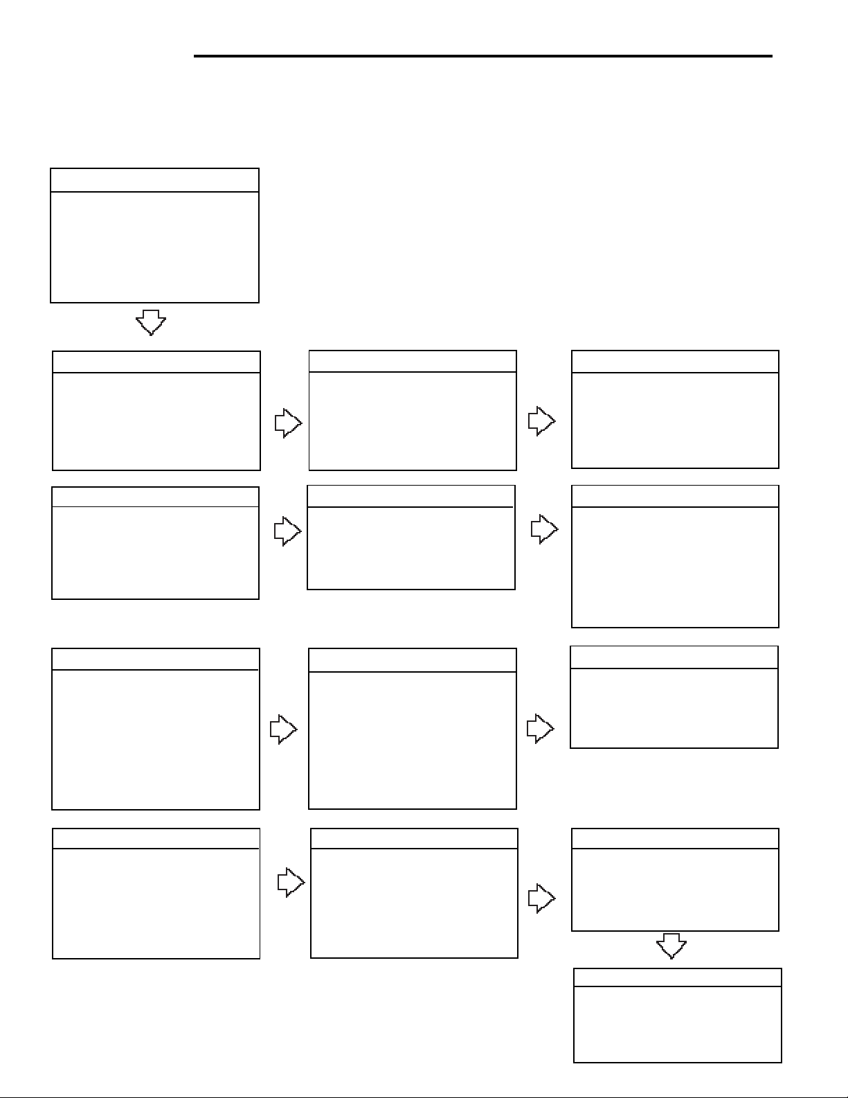
2.6 Scale Base Setup (Cont.)
SETUP SUBMENUS
SCALE
Zero 2%, 18%, 100%
Calunit kg, lb
Grad .0005, .001, .002,
.005, .01....100
Full SC Enter 7 digits
Lock ON/OFF
Exit
CALIBRATION
Span Calibration
User Calibration
Linearity Calibration
Calibration Test (No Lock)
Lock ON/OFF
Exit
READOUT
Stable .5d, 1d, 2d, 5d
Auto 0 OFF, .5d, 1d, 3d
Filter -0-, -1-, -2-, -3Sleep ON /OFF
Lock ON /OFF
Exit
PRINT
Auto Print OFF, Cont, Inter, On Stb
Interval Enter 1 seconds
Stable ON/OFF
Numeric ON/OFF
GMP Cont ON/OFF
GMP Tare ON/OFF
Reference ON/OFF
Lock O N /OFF
Exit
DATE
Type m/d/y
Set Date
Exit
GMP DATA
User Number Enter 7 digits
Project Number Enter 7 digits
Scale ID Enter 7 digits
Lock ON/OFF
Exit
RS232
Baud 300, 600, 1200, 2400, 4800,
9600
Parity None, -E-, -Odd-, -0-, -1Data 7 or 8
Stop 1 or 2
Lock ON/OFF
Exit
TIME
Type 12 Hour/24 Hour
Set Time
Exit
GMP SET
Time ON/OFF
Scale ID ON/OFF
User Number ON/OFF
Project Number ON/OFF
Difference ON/OFF
Name ON/OFF
Lock ON/OFF
Exit
LEGAL FOR TRADE
LFT Lock ON/OFF
(Locked using switch)
Exit
MODE
Weigh ON/OFF
Percent ON/OFF
Count ON/OFF
Animal ON/OFF
Checkweigh ON/OFF
Lock ON/OFF
Exit
UNITS
Grams ON/OFF
Kilo ON/OFF
Pounds ON/OFF
Custom ON/OFF
Lock ON/OFF
Exit
12
GLOBAL
List NO/YES
Reset NO/YES
Version Software No.
Lock ON/OFF
Exit
CUSTOM
Factor Enter 7 digits
Exponent Enter +3 to -3
LSD .5, 1, 2, 5, 10, 100
Lock ON/OFF
Exit
Page 13

CD Indicators
2.6 Scale Base Setup (Cont.)
Review the specifications of the scale base to be used with the Indicator. Make sure the settings you select in the
indicator are compatible with the scale base. Alternate displays are shown in this procedure to save space.
Procedure
• Press the Setup button, SCALE is displayed.
ZERO
Zero specifies the percentage of full capacity load (2%,
18% or 100%) that may be cleared by pressing >0<.
Limits may be required in certain applications.
NOTE: 2% Zero capacity is used f or hopper scales or
other large scales where accidental zero would lose the
current weight. Bench and counter scales normally use
100% Zero capacity . Legal f or tr ade applications use
2%.
• Press Enter button, ZERO is displayed.
• Press Enter button, ZERO 2% (default) is displayed.
• Press and select either 2%, 18% or 100%.
• Press Enter button, SA VED is momentarily display ed
then CALUNIT is displayed.
• Press Enter button, CALUNIT kg is displayed.
• Press and select either kg or lb, then press
Enter button, SA VED is momentarily displa yed then
GRAD .
• Press Enter button, GRAD .01 is displayed.
• Press and select desired setting from .0005
to 100 for scale graduation.
• Press Enter button, SAVED is momentarily display ed
and FULL SC is displayed.
• Press Enter button, FULL SC with a 7 digit number is
displayed, with the first digit flashing. Illustration
indicates a 40 kg scale setting.
• Press and or and enter the
desired scale base capacity when using Model CD-31.
Th e numerical keypad can be used for Model CD-33.
Remember that this number represents either pounds
or kilograms, whatever was previously set for cal unit.
• Press Enter button, SAVED is momentarilydisplayed
followed by LOCK.
13
Page 14
CD Indicators
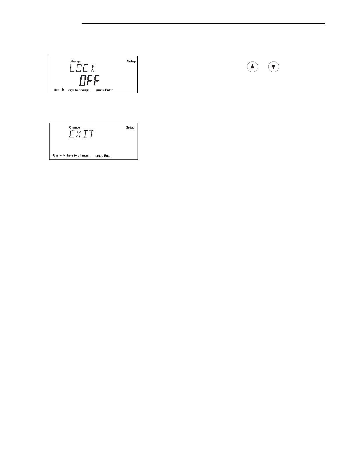
2.6 Scale Base Setup (Cont.)
• Press Enter button, LOCK OFF is displayed, select
either ON or OFF using or buttons, then
press Enter button SAVED is momentarilydisplayed
followed by EXIT.
When LOCK OFF= jumper on the bottom is in place,
Setup is unlocked.
When LOCK ON= jumper was removed, setup is
locked.
• Press Enter button, Indicator returns to a weigh mode.
The Indicator is now matched up with the scale base and
the Indicator parameters may now be set and calibrated.
14
Page 15
CD Indicators
3. SETTING UP YOUR INDICATOR
3. 1 Setting Date and Time
Your Indicator provides date and time data which can be viewed on a computer or printed out on an external printer.
When you put your new instrument into operation for the first time, you should enter the current date and the time.
These settings are retained as long as the Indicator remains connected to a power source.
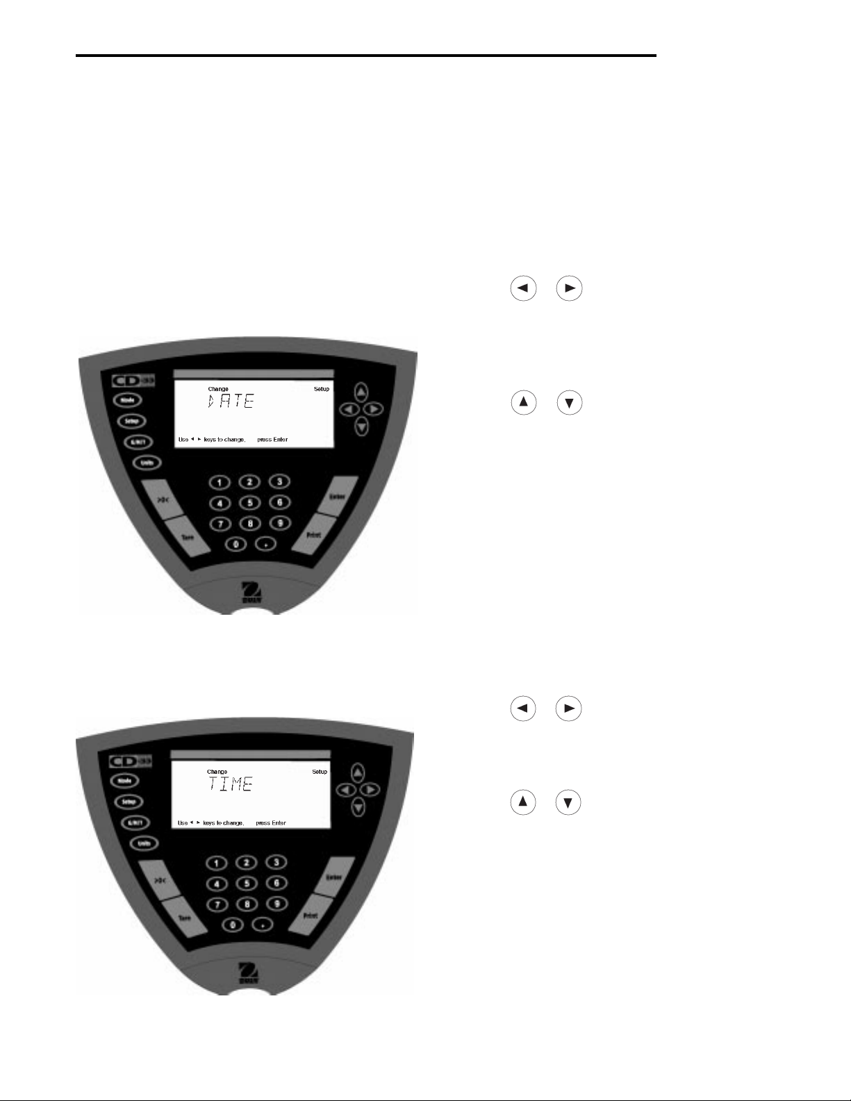
Date
Date is a feature which enables the Indicator to be set to
a U.S.A. date standard or European date standard. U .S .
standard has the month, date, followed by the y ear , each
separated by (/) in the printout. The European date
standard has the day first, followed by the month and
then the year; each separated by a period. The def ault
setting is U.S.A. Standard.
Procedure
• Press the Setup button, SCALE is displayed.
• Press or button and select Date from the
menu.
• Press Enter button, TYPE is display ed.
• Press Enter button, TYPE M d y, d M y, y M d, M y d,
y d M, or d y M is displayed.
• Press or button and select type of date.
• Press Enter button, SAVED is displayed, then SET is
displayed.
• Press Enter button, first digit of date is flashing.
• Using arrow buttons or numerical buttons, enter the
correct date.
• When the correct date is entered, press Enter button,
SA VED displa ys momentarily and EXIT appears.
• Press Enter button, Indicator returns to a weighing
mode.
Time
Time is a feature which enables the Indicator to be set to
the current time in either 12 hour or 24 hour periods. The
default setting is 12 hours.
Procedure
• Press the Setup button, SCALE is displayed.
• Press or button and select Time from the
menu.
• Press Enter button, TYPE is display ed.
• Press Enter button, TYPE 12 hr is display ed.
• Press or button and select 12 hr or 24 hr.
• Press Enter button, SAVED is displa yed momentarily
then SET is displayed.
• Press Enter button, SET with the time is flashing.
• Using arrow buttons or numerical buttons, enter the
correct time.
• When the correct time is entered, press Enter button,
SA VED displa ys momentarily and EXIT appears.
• Press Enter button, Indicator returns to a weighing
mode.
15
Page 16

CD Indicators
3.2 Readout
The Readout menu is used to adapt the Indicator to environmental conditions. It contains five submenus: Stable,
Auto 0, Filter, Sleep, Loc k and Exit. Lock enab les y ou to lock the settings . Review the settings av ailab le below
before proceeding.
Stability
The stability range specifies the weighing results and must be within a preset tolerance limit for a certain time to turn
the stability indicator ON. When a displa yed weight changes be yond the allo wab le range, the stability indicator turns
OFF, indicating an unstable condition. F actory default setting is sho wn in bold type.
.5 d Smallest range: stability indicator is ON only
when displayed weight is stable within .5 divisions.
1 d Normal range.
2 d Medium range.
5 d Largest range, stability indicator is ON even though displayed weight
changes slightly.
When the RS232 communication parameters are configured to print stable data only, the stability range also governs
data output. Displayed data will only be output if it is within the selected stability range.
Auto-0 (Auto-Zero)
Auto-0 minimizes the eff ects of temperature changes and shift on the zero reading. The Indicator maintains the zero
display until the threshold is exceeded. Factory default setting is shown in bold type.
OFFTurns Auto-Zero OFF.
.5 d Sets threshold to .5 divisions.
1 d Sets threshold to 1 division.
3 d Sets threshold to 3 divisions.
Filter
Filter compensates for vibration or excessive air currents. Default settings is shown in bold type.
-0- reduced stability, fastest stabilization time
-1- normal stability , normal stabilization time
-2- more stability, slow stabilization time.
-3- maximum stability, slowest stabilization time.
Sleep On/Off
When set ON, power will be removed from only the displa y in 5 min utes after last weighing. When set OFF, power
remains on all of the time to the Indicator circuitry and display. To turn power ON, press Enter.
Lock
Lock ON/OFF can only be changed when the hardware Lock Switch is set OFF/disabled (jumper on). A menu is
locked when the menu software lock is set ON and the physical Lock Switch is enabled. Lock (jumper removed), when
selected and turned on, locks all of the entries made under the Readout menu. In the locked condition, items may be
looked at in the menu but not changed. When set off, entries may be changed. OFF is the def ault setting.
NOTE: When Lock Switch jumper on the bottom of the Indicator is in place , Lock is OFF and Readout menu can be
changed. When Lock Switch jumper is remov ed, Lock is ON and Readout men u cannot be changed.
16
Page 17

3.2 Readout (Cont.)
CD Indicators
Procedure
• Press the Setup button, SCALE is displayed.
• Press button until READOUT is displayed.
• Press Enter button, STABLE is displayed.
• Press Enter button, STABLE .5d is displayed.
• Press or button and select either .5d, 1d, 2d,
or 5d. 1d is the default setting.
• Press Enter button, SA VED is momentarily display ed.
Display advances to A UTO 0.
• Press Enter button, AUTO 0 .5d is displa y ed.
• Press or button and select either .OFF, .5d,
1d, or 3d. .5d is the default setting.
• Press Enter button, SA VED is momentarily display ed.
Display advances to FILTER.
• Press Enter button, FILTER -1- is displayed.
• Press or button and select either .-0-, .-1-,
-2-, or -3-. -1- is the default setting.
• Press Enter button, SAVED is momentarily displa yed.
Display advances to SLEEP.
• Press Enter button, SLEEP OFF is displayed.
• Press or button and select either ON or OFF.
• Press Enter button, SAVED is display ed momentarily.
display advances to LOCK.
• Press Enter button, LOCK OFF is displayed.
• Press or button and select either ON or OFF.
• Press Enter button, SAVED is display ed momentarily.
display advances to EXIT.
• Press Enter button to save settings. Indicator returns
to weigh mode.
17
Page 18

CD Indicators
3.3 Good Manufacturing Practices (GMP) Data
The GMP Data submenu enables the storage of a user identification number (7 digits), a project number (7 digits), and
a Scale ID number (7 digits). When entered into the Indicator, the identification number, project number and Scale ID
are available when printing providing they are turned on in the GMP Set submenu. A lock setting is also available
which locks the settings.
Procedure
To select any of the items in the GMP Data menu,
proceed as follows:
• Press the Setup button, SCALE is displayed.
• Press or button until GMP DATA is displayed.
• Press Enter button, USER NO is displayed.
• Press Enter button to continue.
• Press or buttons or numerical
buttons and enter a 7 digit number for the user USER
NO number.
• Press Enter button to save setting, PROJ NO is displayed.
• Press Enter button to continue.
• Press or buttons or numerical
buttons and enter a 7 digit number for the project
number.
• Press Enter button to save setting, SCALE ID is dis-
played.
• Press Enter button to continue.
• Press or buttons or numerical
buttons and enter a 7 digit number for the balance ID
number.
• Press Enter button to continue, LOCK is displayed.
• Press Enter button. Using arrow buttons, select ON or
OFF. When Loc k Switch jumper is in place, LOCK
OFF = data can be changed. When Loc k Switch
jumper is removed, LOCK ON= data is locked and
cannot be changed.
• Press Enter button, EXIT is displayed, press Enter
button, Indicator saves settings and returns to weigh
mode.
18
Page 19

CD Indicators
3.4 Good Manufacturing Practices (GMP) Set
Good Manufacturing Practices (GMP) Set submenu allows the selection of: Time, Scale Identification Number , User
Identification Number, Project Number , Diff erence and Name data to be printed. When the selected items are set to
ON, these items are displayed. The default setting is OFF. When an e xternal printer is used, and all items are set ON
and the Indicator is calibrated, the printer will print out calibration data for audit trail purposes and will indicate date,
and time. (It should be noted that the User ID number and Project number must be entered in the GMP Data submenu
before printed data is available).
Procedure
To select any of the items in the GMP Set menu, proceed
as follows:
• Press the Setup button, SCALE is displayed.
• Press button until GMP SET is displayed.
• Press Enter button to save setting.
• Press or button until either TIME, SCALE
ID , USER NO, PROJ NO, DIFF, NAME, LOCK or
EXIT is displayed. Use the next four steps to
turn each entry ON or OFF and to advance to next
menu item.
• Press Enter button to enter submenu.
• Press or button and select either ON or
OFF.
• Press Enter button to save setting.
• Press or button to continue or EXIT.
• Press Enter button to save setting.
19
Page 20

CD Indicators
3.5 Print
The Print menu provides a number of options which can be turned ON or OFF. It contains 8 submenus: Auto Print,
Inter, Stable, Numeric, GMPCont, GMP Tare, Reference and Lock. See descriptions below .
Procedure
• Press the Setup button, SCALE is displayed.
• Press or button until PRINT is displayed.
• Press Enter button to continue.
• Press or button until either AUTOPRT,
INTER, ST ABLE, NUMERIC , GMPCONT, GMPTARE,
REFEREN, LOCK or EXIT is displayed.
• Press Enter button to continue.
• Press or button and select either menu
setting or ON or OFF.
• Press Enter button to save setting.
• Press or button to select next item or EXIT.
• Press Enter button to continue.
Auto Print Feature
When enabled, the Auto Print feature causes the Indicator to automatically output display data in one of three ways:
continuously, at user specified time intervals, or upon stability. Default settings are shown bold.
OFF when set on turns off the auto print feature
Cont when set on, outputs printed data continuously
Inter provides a user specified printing interval
On Stb provides printed data only when a stable reading is achieved
Interval
Can be set to provide a specified printing interval between 1 and 3600 seconds.
Print Stable Data Only
When set On, permits only stable display data to be output. OFF is the default setting.
Print Numeric Data Only
When Numeric Data Only function is turned ON, this allows the indicator to output numeric data only for RS232 output.
OFF is the default setting.
GMP Continuously
When the GMP Continuously function is set ON, it allows the Indicator to output the GMP selections each time a
weight value is printed to the printer. OFF is the def ault setting.
GMP Once After T are
When the GMP Tare function is set ON, it allows the Indicator to output the GMP selections once after tare when the
weight value is printed to the printer. OFF is the default setting.
Reference
When the Reference function is set ON, it prints the value of weight used as a ref erence in either P ercent and P arts
Counting modes. OFF is the default setting.
Lock
Lock ON/OFF can only be changed when the hardware Lock Switch is disabled (jumper on). A menu is locked when
the menu lock is set ON and the Lock Switch is enabled (jumper off). Lock when selected and turned on, locks all of
the entries made under the Print menu. In the locked condition, items may be looked at but not changed in the menu.
When set off, entries may be changed. OFF is the default setting.
20
Page 21

CD Indicators
3.6 RS232
The RS232 menu provides communication parameters which can be set to accommodate external printers or computers. It contains four submenus: Baud rate , Parity, Data and Lock. See descriptions below .
Procedure
• Press the Setup button, SCALE is displayed.
• Press or button until RS232 is displayed.
• Press Enter button.
• Press or button until either BAUD, PARITY,
DAT A, STOP, LOCK or EXIT is displayed.
• Press Enter button to save setting.
• Press or button and select the desired
menu setting.
• Press Enter button.
• Press or button to continue or EXIT.
• Press Enter button to save setting.
Baud Rate
This submenu is used to select the desired baud rate. There are six available baud rates to choose from: 300, 600,
1200, 2400, 4800 and 9600. The def ault setting is 2400.
Parity
Parity can be set to none,Odd, Even, 0, or 1. The default setting is None.
Data
Can be set to 7 or 8. Default is 7.
Stop
Stop bits can be set to 1 or 2. Default is 2.
Lock
Lock ON/OFF can only be changed when the hardware Lock Switch is set disabled (jumper on). A menu is locked
when the menu lock is set ON and the Lock Switch is enabled (jumper off). Lock when selected and turned on, locks
all of the entries made under the RS232 menu. In the locked condition, items may be looked at but not changed in the
menu. When set off , entries ma y be changed. OFF is the default setting.
21
Page 22

CD Indicators
3. 7 Legal for Trade (LFT)
Legal for Trade (LFT) is a software controlled option which can be set to LFT LOCK. When LFT LOCK is set ON,
certain items in the Calibration, Readout, Print, Mode and Units menus are automatically preset and locked. This is
done to permit the Indicator to operate in a legal for trade application and works in conjunction with a Lock Switch
(jumper). Def ault setting is UNLOCKED, which limits display resolution to 1:10,000. See def ault table.
Procedure
When LFTLOCK is set to ON, None of the settings in the
menus which are listed as Locked in the default table can
be altered.
The settings in the menus which are listed as Unlocked in
the default table may be altered if: A) The Locks witch
jumper is on (Lockswitch disabled) or B) The Lockswitch
jumper is off (Lockswitch enabled) and the Menulock is off.
When LFTLOCK is set OFF:
The settings of all menus may be altered if: A) The
Lockswitch jumper is on (Loc ks witch disab led); or B) The
Lockswitch jumper is off (Lockswitch enabled) and the
Menulock is off.
• Press the Setup button, SCALE is displayed.
• Press button repeately until LFT is displayed.
• Press Enter button, LFT LOCK is displayed.
• Press Enter button.
• Press or button and select either ON or OFF.
• Press Enter button, SAVED is momentarily displayed,
then EXIT is displayed.
DEF AUL T T ABLE
LFT and Lock Switch Menu lock Av ailable Settings
Scale Menu
Zero Locked 2%
Calibration Unit Locked lb or kg
Grad Locked 1:10,000 max.
Full Scale Locked ON
Lock Locked ON
Calibration Menu
Span, Linearity, User Locked
CalTest Unlocked
Readout Menu
Stability Unlocked .5d (limited to .5d and 1d)
Auto zero Unlocked .5d (limited to OFF and .5d)
Filter Level Unlocked -1GMP Data Menu Unlocked
GMP Selections Unlocked
Print Options Unlocked
RS232 Menu Unlocked
LFT Menu Lockswitch Locked
Mode menu Locked Weigh
Units Menu Locked Cal unit*
Global Menu Locked
Custom Menu Unlocked
• Press Enter button, Indicator returns to weigh mode.
NOTE: For legal f or trade applications, the indicator must
be physically sealed. Refer to section on LFT Sealing.
When the Indicator is first turned ON and LFT has been
previously set ON, the following display will appear if LFT
is set in the menu and the Lock Switch is set ON.
When the Indicator is first turned ON and LFT has been
previously set ON, the following display will appear if LFT
is set in the menu and Calibration menu is locked, and
the Lock Switch is enabled (jumper off).
CAL SAFE message appears when Lock Switch is
enabled (jumper off) and Calibration menu lock is ON.
If Print Numeric Data is turned ON, then Print Stable Data Only is
locked ON.
* Any unit which was enabled may be selected as a weighing unit. Default is the calibration unit. Custom unit is
disabled in LFT and can not be selected as a weighing unit.
22
Page 23

CD Indicators
3.8 Mode
The Mode submenu permits the selection of 6 modes which can be turned ON or OFF . These modes are: W eigh,
Percent, Count, Animal, Checkweigh and Loc k. W eigh is turned ON and all others have a def ault setting of OFF.
When any of the modes are turned ON, they can be selected for operation from the Mode button.
Procedure
• Press the Setup button, SCALE is displayed.
• Press or button until MODE is displayed.
• Press Enter button.
• Press or button until either WEIGH, PERCENT , COUNT, ANIMAL, CHECKWEIGH, LOCK or
EXIT is displayed.
• Press Enter button.
• Press or button and select either ON or
OFF.
• Press Enter button to save setting.
• Press or button to continue or EXIT.
• Press Enter button to save setting.
Weigh
The W eigh submenu is alw ays set to ON as a default.
Percent
Percent weighing permits you to place a ref erence load on the scale base platf orm, then view other loads as a percentage of the reference. Selection is made using the Mode button. The def ault setting is OFF.
Count
Counting is used when counting quantities of parts. Selection is made using the Mode button. The default setting is
OFF.
Animal
Animal weighing provides special settings to accommodate animal movements. Selection is made using the Mode
button. The def ault setting is OFF.
Checkweigh
Checkweigh mode permits you to weigh an item, set parameters such as minimum weight and over weight.
Subsquent items can be weighed against the criteria set in the Indicator. The parameters are set when in the Mode
operation and set to Checkweigh. The default setting is OFF.
Lock
Lock ON/OFF can only be changed when the hardware Lock Switch is disabled (jumper on). A menu is locked when
the menu lock is set ON and the Lock Switch is enabled (jumper off). Lock when selected and turned on, locks all of
the entries made under the Mode menu. In the locked condition, items may be looked at but not changed in the menu.
When set off, entries may be changed. OFF is the default setting.
23
Page 24

CD Indicators
3.9 Units
The Units submenu permits the selection of the measuring units which can be turned ON or OFF and locked.
Procedure
• Press the Setup button, SCALE is displayed.
• Press or button until UNITS is displayed.
• Press Enter button to continue.
• Press or button until desired measuring unit
is displayed.
• Press Enter button to continue.
• Press or button and select either ON or
OFF.
• Press Enter button to save setting.
• Press or button to select next item or EXIT.
• Press Enter button to continue.
Units
Measuring units settings are made using the Units button. This menu permits the measuring units to be turned ON or
OFF. The def ault setting is OFF for all units except kilograms which is set ON.
Lock
Lock when selected and turned ON, locks all of the entries made under the Units button. The def ault setting is OFF.
3.10 Global
This menu contains two functions which can be set to either a yes or no type of operation. These functions are: List,
and Reset. The def ault settings are NO. Global List is a convienent method of e xamining which parameters are set up
in the Indicator. The parameters do not show up on the displa y but print out when selected. The Global menu contains
the List function. When Version is selected, the software revision of the Indicator is displayed.
Procedure
• Press the Setup button, SCALE is displayed.
• Press or button until GLOBAL is displayed.
• Press Enter button to continue.
• Press or button until either LIST, RESET ,
VERSION, LOCK or EXIT is displayed.
• Press Enter button to continue.
• Press or button and select either YES or
NO for LIST and RESET. When either LOCK or EXIT
is selected, ON or OFF settings are available..
• Press Enter button to save setting.
• Press or button to select next item orEXIT.
• Press Enter button to save.
24
Page 25

CD Indicators
3.10 Global (Cont.)
List
This submenu can be used to output a listing of current menu settings via the RS232 interface. When YES is selected,
all menu settings will be output either to an external printer or computer. To use this feature, your Indicator must be
connected to a computer or printer. The def ault setting is OFF.
The partial sample shown, indicates the status in the
SAMPLE PRINTOUTS
menus.
CD-31\CD-33
xxxxxxxxx
Time= 12hr 03:19:51 PM
Date= m/d/y 12/01/99
Function = Weigh
ReadOut Menu
Stb= .5d
AZT= .5 d
Filter= 1
GMP Menu
Time/Date= On
Scale Id= On
User No.= On
Proj No.= On
DIFF= On
Name= On
Print Menu
Auto Print= On Stb.
Interval= 1
Stable Print= On
NU= On
GMP Cont = On
GMP on Tare = On
Print Ref= On
RS232 = 2400: N
LFT is Off
Mode Menu
WEIGH= On
PERCENT= On
COUNT= On
ANIMAL= On
CHECKWEIGH = On
EXP WGT= Off
Lock Switch is Off
Menu Locks
RS232= Off
READOUT= Off
GMPSET= Off
MODE= Off
UNITS= Off
PRINT= Off
GMP Data = Off
CAL= Off
GLOBAL= Off
CUSTOM= Off
SCALE=Off
Enabled Units:
g
kg
custm
C. Units:
1.000000
Reset
Reset when set to YES will reset the Indicator to factory default settings. The default setting is NO.
Version
Displays software re vision number f or servicing purposes. This number is installed with the Indicator.
Lock
Lock when selected and set to ON, locks all of the entries made under the Global menu. The def ault setting is OFF.
25
Page 26

CD Indicators
3.11 Custom Unit
Custom Unit is enabled when Custom Unit Setup under Units Menu is turned ON. This f eature can be used to create
your own custom weighing unit. It permits entering a conversion factor which the scale will use to convert kg to the
desired unit of measure.
Conversion Weight Weight
Factor x in = in
kg custom unit
Conversion factors are expressed in scientific notation and entered
into the balance in three parts:
• a number between 0.1 and 1.999999 called the mantissa
• a power of 10 called the exponent
• a least significant digit (LSD).
SCIENTIFIC NOTATION
Number
Between
Conv. 0.1 and P o wer Man-
Factor 1.999999 of 10 tissa Exp.
123.4 = .1234 x 1000 = .1234 x 10
12.34 = .1234 x 100 = .1234 x 10
1.234 = .1234 x 10 = .1234 x 10
.1234 = .1234 x 1 = .1234 x 10
.01234 = .1234 x .1 = .1234 x 10
.001234 = .1234 x .01 = .1234 x 10
.000123 = .123 x .001 = .123 x 10
EXPONENTS
E-3 Moves decimal point 3
places to the left.
E-2 Moves decimal point 2
places to the left.
E-1 Moves decimal point 1
place to the left.
E0 Leaves decimal point
in normal position.
E1 Moves decimal point 1
place to the right.
E2 Moves decimal point 2
places to the right.
E3 Moves decimal point 3
places to the right.
3
2
1
0
-1
-2
-3
Procedure
• Press the Setup button, Scale is displayed.
• Press or button until CUST OM is displayed.
• Press Enter button to save setting, FACTOR is
displayed.
• Press Enter button, the mantissa of the current conversion factor is displayed. This is a number between 0.1 and 1.999999 with the first digit flashing. For
conversion factors outside of this range, the exponent will be used to move the decimal point.
• Press or buttons or numerical
keypad and enter a 7 digit number for the conversion factor.
• Press Enter button, EXP (exponent) is displayed.
• Press Enter button, 0 (exponent) is displayed.
• Press or button and select exponent value
either -3, -2, -1, 0, 1, 2, or 3.
26
Page 27

CD Indicators
3.11 Custom Unit (Cont.)
3.12 Menu Lock-Out Protection
Access to the various menus can be disabled by inserting
the Lock Switch jumper located on the bottom of the
Indicator underneath the Terminal Block. See figure f or
location. The Lock Switch jumper when removed, locks
out all menus which have had LOCK turned ON. The
default setting for the Lock Switch jumper is OFF (jumper
on).
Type Approved/Legal for Trade
Indicator Sealing
All CD-31 and CD-33 Indicators may be sealed for type
approved/legal for trade applications. A sealing kit is
provided with the Indicator. The kit includes a lead seal
with wire, screws and cover as shown.
Procedure (Cont.)
• Press Enter button, SA VED is momementary dis-
played f ollow ed by LSD. There are 6 LSD (least
significant settings you can choose from (see table).
LSD’s
LSD .5 Adds one decimal place
display counts by 5’s.
LSD 1 Display counts by 1’s.
LSD 2 Display counts by 2’s.
LSD 5 Display counts by 5’s.
LSD 10 Display counts by 10’s.
LSD 100 Display counts by 100’s.
• Press Enter button, LSD 1 is displayed.
• Press or button and select LSD value.
• Press Enter button, LOCK is displayed.
• Press Enter button, LOCK OFF is displayed.
• Press or button and select ON or OFF.
• Press Enter button, EXIT is displayed.
• Press Enter button, Indicator returns to weigh mode.
For type approv ed Indicators, consult local Weights and
Measures officials to determine sealing method requirements.
After the Indicator has been set up properly , calibrated
and the menus are locked out (refer to paragraph 4.1
Calibration), proceed to seal the indicator.
For a lead and wire seal, place the sealing plate into
position and run sealing wire through holes in plastic
retainers. Run wire through lead seal and crimp closed as
shown. Alternate LFT paper seal should be positioned
half on the sealing plate and half on the plastic cover .
Indicator Connection Compartment Open Indicator Connection Compartment Sealed
27
Page 28

CD Indicators
4. OPERATING YOUR INDICATOR
4.1 Calibration
Model CD-31 and CD-33 Indicators offer a choice of four calibration methods: Span, User, Linearity, and CalT estTM.
•
Span
- Span calibration ensures that the Indicator reads correctly within specifications using a
weight value of 100% of capacity.
• User
• Linearity
• Cal Test
•
- User calibration is a method where the Indicator can be calibrated using a mass between 10%
and 100% of capacity and by entering that numeric value into the Indicator .
- Linearity calibration minimizes deviation between actual and displayed weights within the
Indicator's weighing range. Three weight values are used: zero , a weight value at or near
midpoint and full scale.
- User may enter calibration test point by entering that numeric v alue into the Indicator .. The
difference in weight is indicated.
Lock
- Can be set on or off. When set on, Span, User and Linearity are lock ed out and cannot be
used.
Calibration Menu Protection
NOTES:
• Calibration may be locked out to prevent unauthorized personnel from changing calibration. If calibration has been
locked out, you can only access Cal Test.
• To lock out calibration menu, after calibration, refer to the section titled paragraph 3.12, Menu Lock-Out Protection.
Calibration Masses
Before beginning calibration, make sure masses are available. If you begin calibration and realize calibration masses
are not availab le, e xit the menu. The Indicator will retain previously stored calibration data. Calibration should be
performed as necessary to ensure accurate weighing. Masses required to perform the procedures should be in
compliance with the requirements of the scale base being used with the Indicator.
NOTE:
Any of the calibration modes can be terminated
at any time
28
by pressing either the Mode, Units or Setup buttons.
Page 29

4.1.1 Span Calibration
Span calibration requires a mass equal to 100% of the scale base capacity.
Procedure
• Press the Setup button, SCALE is displayed.
• Press button until CAL is displayed.
• Press Enter button, CAL TYPE is displayed.
• Press Enter button, CAL TYPE SPAN is displayed.
• Press Enter button, CLR PAN is displayed. Clear
the pan.
• Press Enter button, WORKING is momentarily displayed, then PUT WT is displayed (capacity of base)
on the pan.
• Place specified calibration mass on pan. The illustration sample indicates 40 kilograms.
CD Indicators
• Press Enter button, WORKING is display ed. After a
few seconds CAL SET is displayed; the display then
returns to WEIGH mode.
• Span calibration is completed.
• Remove calibration mass from the pan.
29
Page 30

CD Indicators
4.1.2 User Calibration
User calibration is used when it is desired to calibrate the Indicator using a mass of known value from 10% to 100% of
the capacity of the scale base. T o use this calibr ation feature, proceed as follows:
Procedure
• Press the Setup button, SCALE is displayed.
• Press button UNTIL CAL is displayed.
• Press Enter button, CAL TYPE is displayed.
• Press Enter button, SPAN is displayed.
• Press button to select user calibration. CAL
TYPE USEr is displayed.
• Press Enter button; the display indicates the last
calibration mass value which was entered with the
first digit flashing. (Sampleillustrates 10kg).
• Press and or and enter the
desired mass value when using Model CD-31. The
numerical keypad can be used for Model CD-33. This
number must be at least 10% of the full span value.
• Press Enter button, CLR P AN is displa yed.
• Press Enter button,WORKING is momentarily displayed, then PUT WT 10 kg is displayed.
• Place specified calibration mass on pan.
• Press Enter button, WORKING is display ed. After a
few seconds CAL SET is displayed, the display then
returns to WEIGH mode and indicates mass on pan.
• Remove calibration mass from the pan.
• User calibration is completed.
(FLASHING)
30
Page 31

CD Indicators
4.1.3Linearity Calibration
Linearity calibration utilizes three calibration points; one at zero , center span and full span. This method minimizes
deviation between actual and display ed weights within the Indicator's weighing range. Three weight values are used;
zero, a weight v alue at or near midpoint of the Indicator's weighing range and a weight v alue at specified capacity.
Sample display illustrates a 40 kg scale base.
Procedure
• Press the Setup button, SCALE is displayed.
• Press button UNTIL CAL is displayed.
• Press Enter button, CAL TYPE is displayed.
• Press Enter button, SPAN is displayed.
• Press button to select linear calibration. CAL
TYPE Lin is displayed.
• Press Enter button, CLR P AN is displa yed.
• Press Enter button, WORKING is momentarily dis-
played, then PUT WT 20kg is displayed.
• Place specified calibration mass on pan.
• Press Enter button, WORKING is display ed. After a
few seconds, displa y changes to PUT WT 40kg.
The displayed weight is the full capacity of the
Indicator.
• Place specified calibration mass on pan.
• Press Enter button, WORKING, is displa yed. After a
few seconds, CAL SET is displayed; the display then
returns to WEIGH mode and indicates mass on pan.
• Remove calibration mass from the pan.
• Linearity calibration is completed.
31
Page 32

CD Indicators
4.1.4 Calibration Test
Calibration test feature allows a check of a known calibration mass against the last stored calibration information in the
indicator. Sample display illustrates a 40 kg scale base using a 10kg mass.
Procedure
• Press the Setup button, SCALE is displayed.
• Press button UNTIL CAL is displayed.
• Press Enter button, CAL TYPE is displayed.
• Press Enter button, SPAN is displayed.
• Press button to select calibration test,CAL
TYPE CALtESt is displayed.
• Press Enter button, TEST WT is display ed and the
last calibration mass value which was entered with the
first digit flashing. (Sampleillustrates 10kg).
• Press and or and enter the
desired mass value when using Model CD-31. The
numerical keypad can be used f or Model CD-33. This
number must be at least 10% of the full span value.
• Press Enter button, CLR P AN is displa yed.
• Press Enter button,WORKING is momentarily displayed, then PUT WT 10 kg is displayed.
• Place specified calibration mass on pan.
• Press Enter button, WORKING is display ed. After a
few seconds , WEIGH DIFF is displayed.The display
now indicates the actual difference in weight between
the previous weight value which was stored in the
Indicator. After approximately 8 seconds, the display
returns to the WEIGH mode and indicates the weight
on the pan.
• Remove calibration mass from the pan.
32
Page 33

CD Indicators
4.1.5 Calibration GMP Printout
If any option in the GMP Set Menu is turned On, GMP automatically prints data after calibration is completed.
Span Calibration Printout
When performing Span calibration with all GMP options
turned on, a printout is automatically made after the
calibration is completed.
Linearity Calibration Printout
When performing a Linearity calibration with all GMP
options turned on, a printout is automatically made after
the calibration is completed.
- - - - - SPAN CAL - - - - - 12/01/99 1:10:00 PM
Scale Id 1234
Cal: 40kg
Old: 39.99kg
Dif: 0.01kg
Wt.
Ref......................................
USER NO 2056853
PROJ NO 100012
Name........................................
- - - - - END - - - - -
- - - - - LIN CAL - - - - - 12/01/99 1:20:00 PM
Scale Id 1234
Cal: 40kg
Old: 39.99kg
Dif: 0.01kg
Wt.
Ref......................................
USER NO 2056853
PROJ NO 100012
Name........................................
Calibration Test Printout
When performing a Calibration Test with all GMP options
turned on, a printout is automatically made after the
calibration is completed.
- - - - - END - - - - -
- - - - - CAL TEST - - - - - 12/01/99 1:30:00 PM
Scale Id 1234
Cal: 10kg
Act: 10kg
Dif: 0.00kg
Wt.
Ref......................................
USER NO 2056853
PROJ NO 100012
Name........................................
- - - - - END - - - - -
33
Page 34

CD Indicators
4.2 Weighing
The Indicator is shipped with kilograms only enabled. When the Indicator is to be used with other Type Approved/Legal
for Trade units of measure, the desired unit must be enabled. Ref er to paragraph 3.9 to enable other measuring units.
The Indicator is equipped with a G/N/T button which allows the viewing of gross weight, net weight and tare weight. A
T are button allo ws taring the weight of container , and a separate >0< zero button, z ero's the Indicator display reading.
Weighing Procedure
• Press >0< to rezero the display.
• Press Units button to select measuring unit. If an
error code appears, refer to paragraph 5.2.
• Press or button for desired measuring unit.
• Press Enter button, Indicator is now ready for weigh-
ing.
• Press >0< to rezero the display.
• Place the object(s) or material to be weighed on the
pan. Example illustrates a 2kg weight.
• Wait for the Stable indicator to appear bef ore readin g the weight.
4.2.1 Manual Taring
When weighing material or objects that must be held in a container , manual taring stores the container weight in the
Indicator’s memory, separate from the weight of the material in the container.
When a container has been placed on the pan and tared, its weight is stored in memory . Adding material to the
container is shown as NET weight. The gross weight is a combination of the tared weight and the material. The G/N/T
button allows switching between GR OSS, NET and TARE weights.
Procedure
• Press >0< button with no load on the pan to set the
Indicator reading to zero.
• Place an empty container on the pan. Its B/G weight
is displayed.
• Press the Tare button, display blinks until stable
weight readings are received, then indicates NET
WEIGH 0.00. The container’ s w eight is stored in
memory.
• Add material to the container. As material is added,
its net weight is displayed.
• Removing the container and material from the pan will
cause the Indicator to display the container’s weight
as a negative number . The tared w eight will remain in
memory until the Tare b utton is pressed again or the
Indicator is turned off.
• Pressing Tare clears tare from memory .
34
Page 35

CD Indicators
4.2.2 Preset Taring
Preset taring is used to enter a tared weight via the numerical keypad. If a container's weight is known, the Indicator
may be preset using the numerical keypad to enter the w eight. When using this feature, a time constraint of 4 seconds
is imposed to start entering data, otherwise the Indicator defaults back to a weighing mode.
Procedure
• Press >0< button with no load on the pan to set the
Indicator reading to zero.
• Press the number 0 on the numeric keypad, the
display indicates P>TARE 00000.00 kg with the
second digit blinking. Using the keypad, enter the
desired tare weight. Remember the weight is either in
pounds or kilograms whatever w as set pre viously. If
the number is not entered, the display indicates an
ERROR CODE 2.1; this is normal. The Indicator
returns to a weighing mode automatically . If entered
correctly , the tare w eight is stored in the Indicator.
• Press Enter button, Indicator is now ready for weigh-
ing. The displa y indicates NET WEIGH and the
amount of tare weight as a negative number . The
illustration indicates a 2kg weight. The next two steps
are for an empty container and a full container .
T are weight
Net weigh - container tared
Container with material
• Place the empty container on the pan. If the weight
entered was correct, the display indicates 0.00 kg.
Material may be added to the container, the displa y
indicates the net weight.
• Place a container with material on the pan. The
display indicates NET WEIGH of the material only. The
weight of the container which was entered is automatically subtracted. Illustration indicates a 10kg of
material in a 2kg container.
• Each press of the G/N/T button will advance the
display to NET WEIGH (net w eight), B/G WEIGH
(gross weight) which includes the container's weight,
and PT WEIGH (preset tare weight of the container).
Th e tare weight remains in memory until the Tare b utton is pressed or the Indicator is unpluged from the
power source.
• Pressing Tare clears tare from memory .
Gross weight material and container
35
Page 36

CD Indicators
4. 3Percent Weighing
Percent W eighing is
permits you to place a reference load on the pan; then view other loads as a percentage of the ref erence. The load you
place on the pan as a reference may be displayed as any percentage you select from 5% to 100% (in 1% increments).
100% does not necessarily have to represent the reference load. Subsequent loads, displayed as a percentage of the
reference are limited only by the capacity of the scale base. The default setting is Ref erence 100%. Refer to paragraph 3.8 to enable percent weighing.
enabled only
when Percent is turned ON in the Mode submenu under Setup . P ercent weighing
Procedure
• Press the Mode button, WEIGH is display ed.
• Press or button until PERCENT is displayed.
• Press Enter button, PUT>PAN 100% or whatever was
set last time is displayed. If a container is used, the
Indicator can be tared at this point. The % display
momentarily blanks while the Indicator is taring out.
• Put the reference load on the pan.
• Press or button and select reference
weight percentage (Percent Range 5 to 100). Hold
button down for fast change.
(T are was entered)
• Press Enter button to save setting, WORKING is
displayed ... calculating reference weight. Indicator
displays reference weight for 5 seconds in selected
measuring unit, then displays the percentage.
• Remove the reference weight from the pan and replace it with another load. The second load is displayed as a percentage of the reference. Container
can be tared anytime during operation: container on
scale, press Tare button. When Tare was entered,
display always shows NET weight (G/N/T button
disabled).
NOTE: The PERCENT displa y (number of digits) is a
function of the accuracy of the Indicator and the size of
the reference weight. The display examples w ere with a
2kg mass used with an 40kg scale base.
36
Page 37

CD Indicators
4.4 Parts Counting
Parts Counting is
Mode button. In the parts counting mode, the Indicator displays the quantity of parts you place on the pan. Since the
Indicator determines the quantity based on the average weight of a single part, all parts must be reasonably uniform in
weight.
enabled only
when Count is turned ON in the Mode submenu under Setup and selected with the
Procedure
• Press the Mode button.
• Press or button until COUNT is displayed.
• Press Enter button to save setting, PUT>PAN 10 PC
is displayed (default setting), Indicator will retain last
sample size saved.
• Press Tare if taring is required. Container can be
tared anytime during operation; container on scale,
press Tare button. When Tare was entered, display
always shows NET weight (G/N/T button disabled).
• Press or button and select sample size.
Sample size is 5 to 1000 pieces.
(T are was entered)
• Place sample size on the pan.
• Press Enter button to continue, display indicates
WORKING.
Indicator displays the reference weight of an individual
piece part for 5 seconds and then displays the total
number of pieces on the pan.
• Remove the sample and place parts to be counted on
the pan. Indicator displays number of pieces.
• T o return to weighing mode, press MODE button,
COUNT is displayed.
• Press button until WEIGH is displayed, then
press Enter button. Indicator is now in a weighing
mode.
37
Page 38

CD Indicators
4. 5 Animal Weighing
Animal Weighing is
enabled only
when Animal is turned ON in the Mode submenu under Setup.
Procedure
• Press the Mode button, WEIGH is display ed.
• Press or button until ANIMAL is displayed.
• Press Enter button to continue, LEVEL is displayed.
• Press or button to change animal weighing
level, 0, 1, 2 or 3. 0 level represents an inactive
subject, 3 is used for a very active subject.
• Press Enter button to continue, A UT O is displa y ed.
• Press or button to select AUT O ON or OFF.
• Press Enter button to continue.
When the AUTO function is set ON, different subjects can
be weighed one after another without pressing any
buttons. When the Indicator displays READ Y, simply
place subject on pan.
Starting Animal Cycle
• Place animal container if used on pan.
• Press Tare to tare the container . Note: preset tare also
can be used.
• Place subject on pan.
• The animal cycle will automatically start if AUTO w as
set to ON.
• Press Enter button to start animal cycle if AUTO was
set to OFF.
During Animal Cycle
• Display shows countdown to AM0.
Completed Animal Cycle
• Indicator displays weight until subject is removed
from the pan. Display returns to ANIMAL READY if
Indicator was set to A UT O .
• T o return to weighing mode, press MODE button,
ANIMAL is displayed.
• Press button until WEIGH is displa y ed, then
press Enter button. Indicator in now in a weighing
mode.
38
Page 39

CD Indicators
4.6 Checkweigh
Checkweigh is
entering a minimum weight value and a maximum weight value though the numerical ke ypad or arrow b uttons. You can
establish minimum and maximum values f or repeitiv e weighing of identical objects. This is suited for production where
a large number of items have to be checked against preset parameters.
enabled only
when Checkweigh is turned ON in the Mode submenu under setup. Checkweigh permits
Procedure
• Press the Mode button, WEIGH is display ed.
• Press or button until CHECK W is displayed.
• Press Enter button to continue, MIN 0000000 is displayed with the first digit blinking.
• Using the numerical keypad or arrow buttons, enter
the minimum acceptable weight for the item being
checked. Sample illustrates 1.90kg.
• Press Enter button to continue, the display indicates
MAX 0000000 with the first digit blinking.
NOTE: W eights are not accepted unless entered as a
multiple of display increment.
• Using the numerical keypad or arrow buttons, enter
the maximum acceptable weight for the item being
checked. Sample illustrates 2.10kg
• Press Enter button to continue, UNDER is displayed
with no object on the pan. Place the item to be
checked on the pan. If the item is within the tolerance
you set, the display indicates OK with the weight of
the item. If the item is over weight, the display
indicates OVER with the weight displa y ed.
• To check similiar items, simply remove the first item
and place another item on the pan to check. It is not
neccessary to press any buttons to check additional items. Container can be tared anytime during
operation: container on scale, press Tare button.
When Tare was entered, display always shows NET
weight (G/N/T button disabled).
• T o return to weighing mode, press MODE button,
CHECK W is displa yed.
• Press button until WEIGH is displayed, then
press Enter button. Indicator in now in a weighing
mode.
(T are was entered)
39
Page 40

CD Indicators
4.7 Printing Data
Printing data to an external computer or printer requires that the communications parameters in the Setup menu, Print
options and communication parameters be set first. Ref er to paragr aph 3 Setting Up Your Indicator. When time, date ,
GMP Data, Print and RS232 data is set, the printout data will reflect whatever parameters are turned on.
Procedure
• Press the Print button. Printing to an external printer
or computer will occur each time the Print button is
pressed. If the autoprint feature is turned on, printing
can occur in a continuous fashion, at specified intervals or each time a stable reading is achieved.
Sample printout is shown below with time, date and
GMP data turned on and a weight of 2.0kg.
SAMPLE PRINTOUT
12/01/99 12:01:37 PM
Bal Id 0000001
USER NO 0000020
PROJ NO 0000010
Name..........................
2.00
Printouts are controlled by the GMP Set Menu and the
selection of GMP Cont. or GMP T are in the Print Menu.
4.7.1 RS232 Commands
All communication is accomplished using standard ASCII format. Characters shown in the following table are acknowledged by the Indicator . Inv alid command response "ES" error indicates the Indicator has not recognized the command.
Commands sent to the Indicator must be terminated with a carriage return (CR) or carriage return-line line feed (CRLF).
Data output by the Indicator is always terminated with a carriage return - line feed (CRLF).
4.7.2 Output Formats
Data output can be initiated in one of three ways: 1) By pressing PRINT; 2) Using the Auto Print feature; 3) Sending a
print command (“P”) from a computer.
The output format is illustrated in the RS232 command table which follows.
40
Page 41

4. 7 Printing Data (Cont.)
4.7.2 Output Formats (Cont.)
CommandCommand
Command
CommandCommand
CharacterCharacter
Character
CharacterCharacter
??
? Print current mode: g, kg, custm, %, #
??
nnnAnnnA
nnnA Set Auto Print feature to "nnnn".
nnnAnnnA
nnnn=0 Turns feature OFF
nnnn=S Output on stability
nnnn=C Output is continuous
nnnn=1-3600 Sets Auto Print interval
CC
C Begin span calibration.
CC
FF
F Print current function.
FF
xlxl
xl Set Averaging Filter to "x", where x = 0 to 3.
xlxl
If LFT, level 0 to 1.
0=minimum level
1=
2=
3= maximum level
LL
L Begin linearity calibration.
LL
xMxM
xM Places terminal in mode "x", where x = 1 to 4.
xMxM
If unit is not already enabled, command returns ES.
1=grams
2=kilograms
3= pounds
4= custom units
PP
P Print display data.
PP
xSLxSL
xSL Set stable data only printing TO "X", where x = 0 to 3.
xSLxSL
If LFT, x=0 or 1.
0=.5d
1= 1d
2= 2d
3=5d
TT
T Same effect as pressing Tare Key.
TT
NN
N Shows copyright notice.
NN
VV
V Print software version number.
VV
EscVEscV
EscV Print scale ID
EscVEscV
xZxZ
xZ Set Auto Zero to "x", where x=0 to 3.
xZxZ
If LFT, Auto Zero level from 0 to 1.
0=off
1=0.5d
2=1d
3=3d
x%x%
x% Set % reference weight. Uses real number "x" as current Percent Reference Weight.
x%x%
Weight must be entered in Calibration Units.
x#x#
x# Set PC reference weight. Uses real number "x" as current Parts reference Weight. Weight
x#x#
must be entered in Calibration Units.
EscREscR
EscR Resets setup and print menus to factory defaults.
EscREscR
CAUTION: This will reset RS232 configuration.
##
# Print current Parts Count Reference Weight in the most recently used Units.
##
%%
% Print current Percent Reference Weight in the most recently used Units.
%%
xFxF
xF Set current function to "x", where x=0 to 4.
xFxF
If mode is not already enabled, command returns ES.
0=None (normal weigh)
RS232 COMMAND T ABLE
DescriptionDescription
Description
DescriptionDescription
CD Indicators
41
Page 42

CD Indicators
4. 7 Printing Data (Cont.)
4.7.2 Output Formats (Cont.)
CommandCommand
Command
CommandCommand
CharacterCharacter
Character
CharacterCharacter
1=percent
2=parts counting
3=animal weighing
4= checkweigh
xAWxAW
xAW Set Animal Level to "x", where x= 0 to 3.
xAWxAW
0= minimum filtering
1=
2=
3= maximum filtering
xExE
xE Turn Auto restart in Animal mode on or off.
xExE
Where x=0 is off and x=1 is on.
xTxT
xT Set tare weight. Uses real number "x" as current tare weight. Weight must be entered in
xTxT
Calibration Units.
IDID
ID Print Current User ID String.
IDID
xIDxID
xID Program User ID String, 1-8 characters.
xIDxID
ACAC
AC Abort Calibration.
ACAC
xUCxUC
xUC Start User Calibration. Uses integer number "x" as calibration weight.
xUCxUC
LELE
LE Show last error code. Response: "Err: x.x".
LELE
xSxS
xS Turn Print Stable Only on or off.
xSxS
Where x=0 is off and x=1 is on.
TIMETIME
TIME Print current time. Note, a "?" will follow if time has not been set.
TIMETIME
mm/dd/yymm/dd/yy
mm/dd/yy Set date command and remove invalid date indicator.
mm/dd/yymm/dd/yy
SETDATESETDATE
SETDATE
SETDATESETDATE
hh:mm:sshh:mm:ss
hh:mm:ss Set time command and remove invalid time indicator. Time must be entered in 24 hr. format
hh:mm:sshh:mm:ss
SETTIMESETTIME
SETTIME
SETTIMESETTIME
DATEDATE
DATE Print current date. Note, a "?" will follow if date has not been set.
DATEDATE
SWSW
SW Shows Lockswitch status.
SWSW
ZZ
Z Same effect as pressing ">0<" Key.
ZZ
NGNG
NG Same effect as pressing the "G/N/T" Key. Cycles through Net, Gross, and tare displays if
NGNG
possible.
EscMEscM
EscM To print out a list of the scale selections.
EscMEscM
EE
E Will start animal cycle when in animal weighing mode.
EE
RS232 COMMAND T ABLE
DescriptionDescription
Description
DescriptionDescription
42
Page 43

CD Indicators
5 CARE AND MAINTENANCE
To keep the Indicator operating properly , it should be k ept clean and free from foreign material. If necessary, a cloth
dampened with a mild detergent may be used.
5.1 T roubleshooting
SYMPTOM
Unit will not turn on.
Incorrect weight reading.
Cannot display weight in desired
unit.
Unable to store menu settings/
changes.
RS232 interface not working.
PROBABLE CA USE(S)
Po wer cord not plugged in or properly
connected to Indicator.
Indicator was not re-zeroed before
weighing.
Indicator not properly calibrated.
Desired unit not enabled.
Enter was not selected.
Menu locked.
Print menu settings not properly set up.
Loose or improper cable connections.
REMEDY
Check power cord connections.
Press >0< with no weight on the
pan, then weigh item.
Recalibrate correctly .
Enable units in Setup menu.
Press Units button until desired
measuring unit is shown.
Press Enter when prompted.
Menu not locked properly.
V erify interf ace settings in RS232
menu correspond to those of
peripheral device.
Check cable connections.
Random segments displayed or
display locks up.
Unstable readings.
Error message display .
Cannot access weighing mode.
Microprocessor locks up.
Excessive air currents.
Vibration on platform surface.
Desired weighing mode is not enabled.
Unplug from the wall outlet and
plug in. If condition persists, unit
must be serviced.
Check environmental conditions.
Place scale base on a stable
surface or change averaging level.
See Error Codes list.
Enable weighing mode.
Press mode until desired weighing
mode is displayed.
43
Page 44

CD Indicators
5. 2 Error Codes List
Error Codes List
The following list describes the various error codes and which can appear on the display and the suggested remedy.
Tare Errors
2.0 Tare timeout - Indicator unstab le during tare attempt.
2.1 Preset tare timeout - (more than 4 seconds between key presses).
2.2 Zero timeout - Indicator unstable during zero attempt.
Calibration Errors
3.0 Improper or missing mass used for calibration. Recalibrate with correct masses.
User Errors
4.4 RS232 buffer full.
5.1 Scale settings below minimum resolution. (Full Scale/Graduations < 500).
5.2 T oo many divisions allow ed w/current Grad and Full Scale settings. Increase Grad size, reduce capacity, or
recalibrate.
5.3 Unit switching error - cannot display weight in selected unit based on current settings for Cal Unit or grad.
See chart for legal display units.
7.0 User entry out of bounds. -- v alue entered f or Hour , Minute , Month, or Da y is out of range.
7.1 F actor entered f or Custom Units <0.1 or > 1.999999.
7.2 Number outside of display capacity.
7.3 Value entered for preset tare is > Full Scale, or is not a m ultiple of the displa y increment (see chart below).
7.4 Value entered for Full Scale is > 1999999 or =0.
7.5 Value entered for User Calibration or Calibration Test Weight is > Full Scale or < 10% of Full Scale.
7.6 Value entered for Print Interval is < 1 or > 3600 seconds.
7.7 Value entered for Chec k Weigh point is > Full Scale, = 0 or is not a multiple of the display increment (Grad).
7.8 Value entered for minimum Check W eigh point > maximum Chec k W eigh point.
Over-Under Load Errors
8.2 Power-on zero out of range. Weight on scale base greater > z ero (2%, 18%, 100%) during power up).
8.3 Capacity exceeded. (weight on pan > Full Scale + display increments).
8.4 Underload condition on scale base (weight on pan < -5 display increments).
CheckSum Errors
9.1 Bad factory checksum. If error persists, have the Indicator serviced.
9.8 User calibration data failed checksum.
44
Page 45

CD Indicators
5.3 Service Information
If the Troubleshooting section does not resolve or describe your problem, you will need to contact an authorized Ohaus
Service Agent. For Service assistance in the United States, please call Aftermarket, Ohaus Corporation toll-free at
(800) 526-0659. An Ohaus Product Service Specialist will be available to help you.
5.4 Replacement parts
Description Ohaus Part No.
AC Adapter North America, 100-132 V ac, 60 Hz 80500435
AC Adapter Continental Europe, 196-253 V ac, 50 Hz 80500436
AC Adapter UK, 196-264 V ac, 50 Hz 80500437
This product is intended to be supplied by a UL Listed Direct-Plug-In P ower unit marked "Class 2" and rated 9V dc , 500mA.
5.5 Accessories
Description Ohaus Part No.
Adjustable Column 80250632
Wall Mounting Brack et 80250633
Scale Base Mounting Plate 80250634
RS232 Interface Cable/Printer 80500432
RS232 Interface Cable/PC 25 Pin 80500431
RS232 Interface Cable/PC 9 Pin 80500433
Printer AS142
5.6 Technical Data
Standard Equipment of CD-31 and CD-33 Indicators
• Indicator power input 9 V dc , 0.5 A
Materials
• Housing GE C6200 Cycoloy plastic.
• Keypad/display overlay polyester
Protection
• Not protected against dust and water .
• Installation category: Class III
MODELMODEL
MODEL
MODELMODEL
Capacity up to 199,999 (Lb or Kg)
Graduation lb/kg 0.0005 - 100
Displayed Resolution 1:10,000 LFT or 1:50,000 (Non LFT)
Weighing modes lb, kg, g
Functions weighing, parts counting, animal weighing, percent, checkweighing
Over range capacity Max capacity + 5 divisions
Stabilization time 1 to 4 seconds, depends on filter selection
Auto-zero tracking capture range OFF, 0.5, 1, or 3 divisions
Zeroing range 2%, 18%, or 100% of capacity
Internal resolution 1:400,000
Span calibration 10 to 100% of capacity
Load cell excitation voltage 5V dc
Load cell input sensitivity 2 or 3mV/V
Load cell drive 4 x 350 ohm cells
Display LCD 2 line; weight and prompt message
Power AC Adapter only
Keyboard 12 function keys 12 function + 11 numeric keys
Time and Date yes
Overall dimensions (WxDxH) in mm 254 x 19.68 x 7.92
Net weight 0.65kg
Shipping weight 0.95kg
CD-31 CD-31
CD-31
CD-31 CD-31
Ambient conditions
The technical data are valid under the following ambient
conditions:
• Operating temperature -10°C to 45°C/14°F to113°F
• Storage temperature -40°C to 70°C/-40°F to158°F
• Relative humidity 10%.......95%, noncondensing
• Height above sea level up to 4000m
CD-33 CD-33
CD-33
CD-33 CD-33
45
Page 46

CD Indicators
Ohaus products are warranted against defects in materials and workmanship from the date of delivery through the duration of the warranty period. During the warranty period, Ohaus will repair , or, at its
option, replace any component(s) that proves to be defective at no charge, provided that the product
is returned, freight prepaid, to Ohaus.
This warranty does not apply if the product has been damaged by accident or misuse, exposed to
radioactive or corrosive materials, has foreign material penetrating to the inside of the product, or as
a result of service or modification by other than Ohaus. In lieu of a properly returned warranty
registration card, the warranty period shall begin on the date of shipment to the authorized dealer. No
other express or implied warranty is given by Ohaus Corporation. Ohaus Corporation shall not be
liable for any consequential damages.
As warranty legislation differs from state to state and country to country, please contact Ohaus or
your local Ohaus dealer for further details.
LIMITED WARRANTY
46
Page 47

CD Indicators
Ohaus Corporation
29 Hanover Road,
Florham Park, NJ 07932, USA
Tel: (973) 377-9000,
Fax: (973) 593-0359
With offices worldwide.
P/N 80'250'639 R1099 © Ohaus Corporation 1999, all rights reserved.
47
 Loading...