

Page 1
Model CD-11 Indicator
Instruction Manual
Indicador Modelo CD-11
Manual de instrucciones
Indicateur modèle CD-11
Manuel d’instruction
*
Page 2

Page 3
3
Ohaus Corporation, 19A Chapin Road, P.O. Box 2033 Pine Brook, New Jersey, 07058, USA
Declaration of Conformity We, Ohaus Corporation, declare under our sole responsibility that the balance models listed below marked with
“CE” - are in conformity with the directives and standards mentioned.
Declaración de Conformidad
indicados a continuación - con el distintivo ,CE’ - están conformes con las directivas y normas citadas.
Déclaration de conformité Nous, Ohaus Corporation, déclarons sous notre seule responsabilité, que les types de balance ci-dessous cité
- munis de la mention «CE» - sont conformes aux directives et aux normes mentionnées ci-après.
Model/Modelo/Modèle CD-11
EC Marking: EC Directive Applicable Standards
Marcado EC Directive EC Normas aplicables
Marquage CE Directive CE Normes applicable
Nosotros, Ohaus Corporation, declaramos bajo responsabilidad exclusiva que los modelos de balanzas
73/23/EEC EN60950-1:2001
Low Voltage
Baja tensión
Basse tension
89/336/EEC EN61326-1: 1997 + A1:98 + A2:01 +A3:03
Electromagnetic compatibility
Compatibilidad electromagnética
Compatibilité électromagnétique
For non-automatic weighing instruments used in an Article 1, 2.(a) application, additional metrological marking according to Annex
IV of Council directive 90/384/EEC must be attached to the instrument
Para instrumentos de pesaje no automático usados en una aplicación descrita en el Artículo 1, 2.(a), se debe colocar sobre el
instrumento una marcación metrológica adicional de acuerdo con el Anexo IV de la Directriz del Consejo 90/384/EEC.
Pour les instruments de pesage non-automatiques utilisés dans une application Article 1, 2.(a), un repérage métrologique
additionnel conforme à l’Annexe IV de la Directive 90/384/EEC du Conseil doit être présent sur l’instrument.
90/384/EEC EN45501:1992
year
Non Automatic Weighing Instruments
Para balanzas no automátäcas
010
Balances à fonctionnement non automatique
1) 2)
M
1) Applies only to certified non-automatic weighing instruments
Aplicable solamente a instrumentos de pesaje aprobados de funcionamiento no automático
S’applique uniquement aux instruments de pesage à fonctionnement non automatique approuvés
2) Valid only for CW-11 terminals in connection with approved load cells
Valable seulement pour les indicateurs CW-11 connectés à des cellules de pesée approuvées.
Válido solamente para terminales CW-11 en conexión con células de carga aprobadas
Date: May, 5, 2006
Ted Xia
President
Ohaus Corporation
Pine Brook, NJ USA
Urs Muller
General Manager
Ohaus Europe
Greifensee, Switzerland
Page 4
Important notice for verified weighing instruments
Weighing Instruments verified at the place of manufacture bear one of the preceding mark on the packing label and
the green ‘M’ (metrology) sticker on the descriptive plate. They may be put into service immediately.
Weighing Instruments to be verified in two stages have no green ‘M’ (metrology) on the descriptive plate and bear one
of the preceding identification mark on the packing label. The second stage of the initial verification must be carried
out by the approved service organization of the authorized representative within the EC or by the national weight &
measures (W+M) authorities.
The first stage of the initial verification has been carried out at the manufacturers work. It comprises all tests according to the adopted
European standard EN 45501:1992, paragraph 8.2.2.
If national regulations limit the validity period of the verification, the user of the weighing instrument must strictly observe the re-verification
period and inform
the respective W+M authorities.
Notificación importante para instrumentos de pesaje verificados
Los instrumentos de pesaje verificados en el sitio de fabricación llevan una de las marcas precedentes en el rótulo del
empaque y la etiqueta de la ‘M’ verde (metrología) en la placa descriptiva. Estos instrumentos se pueden poner en
funcionamiento inmediatamente.
Los instrumentos de pesaje a ser verificados en dos etapas no tienen ninguna ‘M’ verde (metrología) en la placa
descriptiva, y presentan una de las marcas de identificación precedentes sobre el rótulo del empaque. La segunda
etapa de la verificación inicial debe ser llevada a cabo por la organización de servicio aprobada del representante
autorizado dentro de la CE o por las autoridades nacionales de pesos y medidas.
La primera etapa de la verificación inicial ha sido llevada a cabo en el sitio de fabricación. Ésta comprende todas las pruebas
estipuladas por el estándar europeo adoptado: EN 45501:1992, párrafo 8.2.2.
Si las normas nacionales limitan el periodo de validez de la verificación, el usuario del instrumento de pesaje debe seguir estrictamente
el periodo de re-verificación e informar a las correspondientes autoridades de pesos y medidas.
Avis important pour les instruments de pesage vérifiés
Les instruments de pesage vérifiés sur le site de fabrication portent l’une des marques précédentes sur l’étiquette de
l’emballage avec un autocollant M (pour Métrologie) en vert sur la plaque descriptive. Ces instruments peuvent être
immédiatement mis en service.
Les instruments de pesage à vérifier en deux étapes ne portent pas d’autocollant M (pour Métrologie) en vert sur la
plaque descriptive et portent l’une des marques d’identification précédentes sur l’étiquette de l’emballage. La deuxième
étape de la vérification initiale doit être exécutée par l’organisation de service homologuée du représentant agréé au
sein de la CE ou par les autorités nationales de poids et mesures.
La première étape de la vérification initiale a été exécutée sur le site du fabricant. Elle se compose des tests requis par la norme
européenne EN45501:1992, paragraphe 8.2.2.
Si des règlements nationaux limitent la durée de validité de la vérification, il incombe à l’utilisateur dudit instrument de pesage de
respecter strictement la période de re-vérification et d’informer les autorités de poids et mesures respectives.
Page 5
Disposal
In conformance with the European Directive 2002/96 EC on Waste Electrical and Electronic Equipment (WEEE) this
device may not be disposed of in domestic waste. This also applies to countries outside the EU, per their specific
requirements.
Please dispose of this product in accordance with local regulations at the collecting point specified for electrical and
electronic equipment.
If you have any questions, please contact the responsible authority or the distributor from which you purchased this
device.
Should this device be passed on to other parties (for private or professional use), the content of this regulation
must also be related.
Thank you for your contribution to environmental protection.
Eliminación de residuos
De conformidad con las exigencias de la directiva europea 2002/96 CE sobre residuos de aparatos eléctricos y
electrónicos (RAEE), este equipo no puede eliminarse como basura doméstica. Esta prohibición es asimismo
válida para los países que no pertenecen a la UE cuyas normativas nacionales en vigor así lo reflejan.
Elimine este producto, según las disposiciones locales, mediante el sistema de recogida selectiva de aparatos
eléctricos y electrónicos.
Si tiene alguna pregunta al respecto, diríjase a las autoridades responsables o al distribuidor que le proporcionó el
equipo.
Si transfiere este equipo (por ejemplo, para la continuación de su uso con fines privados, comerciales o
industriales), deberá transferir con él esta disposición.
Muchas gracias por su contribución a la conservación medioambiental.
Elimination
En conformité avec les exigences de la directive européenne 2002/96 CE relative aux déchets d'équipements
électriques et électroniques (DEEE), cet appareil ne doit pas être éliminé avec les déchets ménagers. Logiquement,
ceci est aussi valable pour les pays en dehors de l'UE conformément aux règlementations nationales en vigueur.
Veuillez éliminer cet appareil conformément aux prescriptions locales dans un conteneur séparé pour appareils
électriques et électroniques.
Pour toute question, adressez-vous aux autorités compétentes ou au revendeur chez qui vous avez acheté cet
appareil.
En cas de remise de cet appareil (p. ex. pour une utilisation privée ou artisanale/industrielle), cette prescription doit
être transmise en substance.
Merci pour votre contribution à la protection de l'environnement.
Page 6

FCC Note
This equipment has been tested and found to comply with the limits for a Class A digital device, pursuant to Part 15 of the FCC Rules.
These limits are designed to provide reasonable protection against harmful interference in a residential installation. This equipment
generates, uses and can radiate radio frequency energy and, if not installed and used in accordance with the instructions, may cause
harmful interference to radio communications. However, there is no guarantee that interference will not occur in a particular installation. If
this equipment does cause harmful interference to radio or television reception, which can be determined by turning the equipment off and
on, the user is encouraged to try to correct the interference by one or more of the following measures:
• Reorient or relocate the receiving antenna.
• Increase the separation between the equipment and receiver.
• Connect the equipment into an outlet on a circuit different from that to which the receiver is connected.
• Consult the dealer or an experienced radio/TV technician for help.
Industry Canada Note
This Class B digital apparatus complies with the Canadian ICES-003.
Cet appareil numérique de la classe B est conforme à la norme NMB-003 du Canada.
ISO 9001 Registration
In 1994, Ohaus Corporation, USA, was awarded a certificate of registration to ISO 9001 by Bureau Veritus Quality International (BVQI),
confirming that the Ohaus quality management system is compliant with the ISO 9001 standard’s requirements. On May 15, 2003,
Ohaus Corporation, USA, was re-registered to the ISO 9001:2000 standard.
Registro ISO 9001
En 1994, Bureau Veritus Quality International (BVQI) le otorgó a Ohaus Corporation, EE.UU., un certificado de registro ISO 9001 el cual
confirma que el sistema administrativo de calidad de Ohaus cumple con los requerimientos del estándar ISO 9001. En mayo 15 del
2003, Ohaus Corporation, EE.UU., fue registrada nuevamente al estándar ISO 9001:2000.
Enregistrement ISO 9001
En 1994, le Bureau Veritus Quality International (BVQI) a octroyé la certification d’enregistrement ISO 9001 à Ohaus Corporation, ÉtatsUnis d’Amérique, confirmant que le système de gestion de la qualité Ohaus était conforme aux conditions normalisées de l’ISO 9001. Le
15 mai 2003, Ohaus Corporation, États-Unis d’Amérique, a été ré-enregistrée à la norme ISO 9001:2000.
Page 7

CD-11 Indicator
EN-1
TABLE OF CONTENTS
OVERVIEW OF CONTROLS AND INDICATOR FUNCTIONS ................................................................................................. 3
1. GETTING TO KNOW YOUR INDICATOR ..................................................................................................................... 4
1.1 Introduction ....................................................................................................................................................... 4
1.2 Features......... ..................................................................................................................................................... 4
1.3 Safety precautions ................................................................................................................................................ 4
2. INSTALLATION ...................................................................................................................................................... 5
2.1 Unpacking and Checking ....................................................................................................................................... 5
2.2 Selecting the Location ........................................................................................................................................... 5
2.3 Connecting the Indicator to a Scale Base ................................................................................................................ 5
2.4 Connecting the RS232 Interface.............................................................................................................................. 7
2.5 Connecting Power ................................................................................................................................................. 7
2.5.1 AC Adapter ................................................................................................................................................. 7
2.5.2 Battery Installation ...................................................................................................................................... 7
2.5.3 Switching on the Indicator ........................................................................................................................... 8
2.6 Initial Setup ....................................................................................................................................................... 8
2.6.1 Control Functions ........................................................................................................................................ 8
2.6.2 Menu Structure ........................................................................................................................................... 9
2.6.3 Load Parameters....................................................................................................................................... 10
2.6.4 Setup Menu .............................................................................................................................................. 11
2.6.5 Readout Menu .......................................................................................................................................... 13
2.6.6 Print menu ............................................................................................................................................... 17
2.6.7 Lockout Menu ........................................................................................................................................... 19
3. CALIBRATION AND SEALING ................................................................................................................................. 21
3.1 Legal for Trade (LFT) Operation and LFT Sealing ................................................................................................... 25
4. OPERATION ..................................................................................................................................................... 26
4.1 Turning On Indicator ........................................................................................................................................... 26
4.2 Turning Off Indicator ........................................................................................................................................... 26
4.3 Zero Operation .................................................................................................................................................... 26
4.4 Tare Operation .................................................................................................................................................... 26
4.5 Gross/Net/Tare Recall Operation ........................................................................................................................... 27
Page 8

EN-2
CD-11 Indicator
TABLE OF CONTENTS (Cont.)
4.6 Clear Tare Operation ........................................................................................................................................... 27
4.7 Unit Switch Operation .......................................................................................................................................... 27
4.8 Parts Counting Operation ..................................................................................................................................... 28
4.9 Establishing the Average Piece Weight (APW) ....................................................................................................... 28
4.10 Returning to a Weighing Mode ........................................................................................................................... 29
4.11 Returning to a Preset APW ................................................................................................................................. 29
4.12 Display Hold Modes .......................................................................................................................................... 29
4.12.1 Manual Display Hold (dHMAn)................................................................................................................. 29
4.12.2 Semi-automatic Display Hold (dHSEM) ..................................................................................................... 30
4.12.3 Automatic Display Hold (dHAuto) ............................................................................................................. 31
4.13 RS232 Commands ............................................................................................................................................ 31
4.14 Printing Data .................................................................................................................................................... 32
5. CARE AND MAINTENANCE ................................................................................................................................... 33
5.1 Troubleshooting.................................................................................................................................................. 33
5.2 Error Codes List .................................................................................................................................................. 35
5.3 Service Information ............................................................................................................................................. 35
5.4 Replacement Parts .............................................................................................................................................. 35
5.5 Accessories ..................................................................................................................................................... 35
5.6 Technical Data ................................................................................................................................................... 35
Page 9
CD-11 Indicator
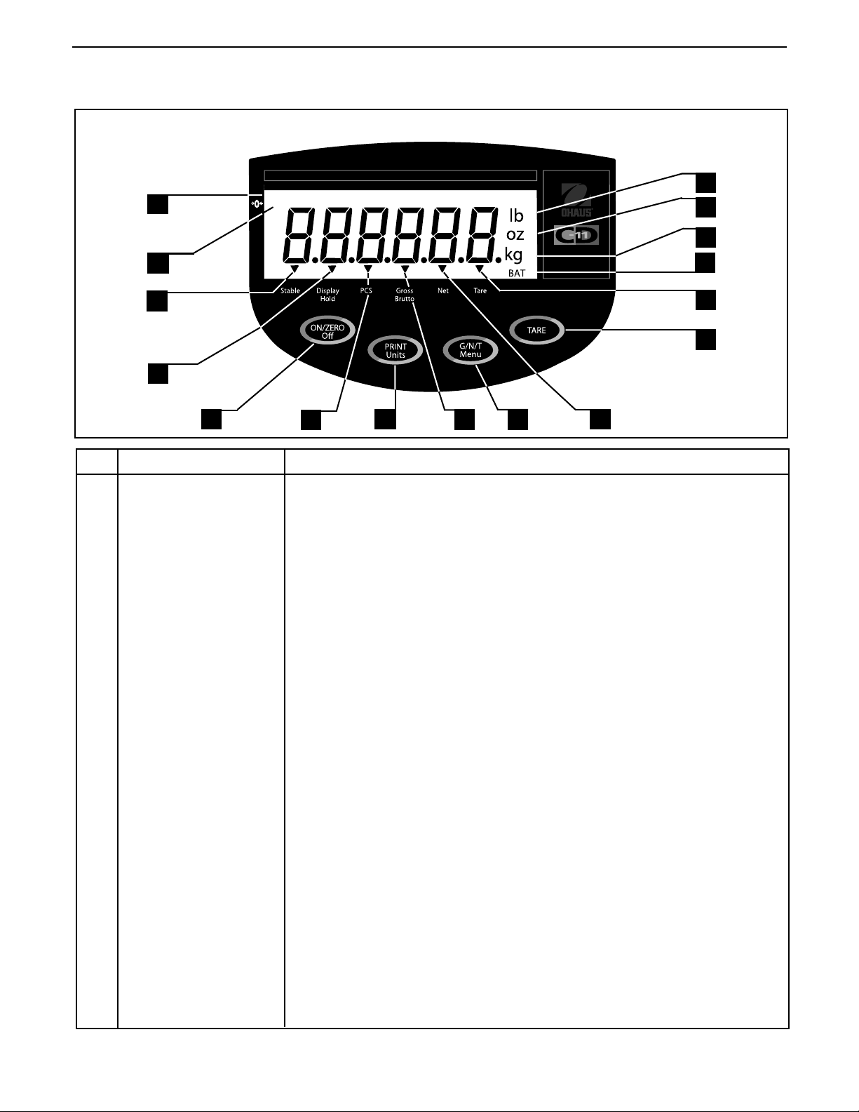
OVERVIEW OF CONTROLS AND INDICATOR FUNCTIONS
1
2 13
*
EN-3
16
15
14
3
12
11
4
5
No. Designation No. Designation
No. Designation
No. Designation No. Designation
1 Display LCD display, indicates weight, modes and setup information.
2 Center of Zero LCD indicator prompt, indicates center of zero when within +/- 0.25d.
3 Stable LCD indicator prompt, indicates that the measured value has become stable.
4 Display Hold LCD indicator prompt, indicates display hold is active.
Off
5 ON/ZERO/
6 Pcs LCD indicator prompt, indicates parts counting function is active.
7 PRINT/
button Turns Indicator on or off. Secondary use, provides zero function.
Units
button Short press, prints data which is displayed on the Indicator.
6
FunctionFunction
Function
FunctionFunction
Long press, changes unit of measure or mode.
When in menus, each press advances through the menus.
When in submenus or establishing Average Piece Weights, each press
toggles through settings.
7
8
9
10
8 Gross Brutto LCD indicator prompt, indicates gross weight.
Menu
9 G/N/T/
10 Net LCD indicator prompt indicates net weight.
11 TARE button When pressed, enters tare value into memory.
12 Tare LCD indicator prompt indicates tare weight.
13 BAT LCD indicator prompt, indicates low battery.
14 kg LCD indicator, when lit, indicates weight in kilograms.
g LCD indicator, when lit, indicates weight in grams.
15 oz LCD indicator, when lit, indicates weight in ounces.
16 lb LCD indicator, when lit, indicates weight in pounds.
button Recalls Gross/Net/Tare. Long press allows entry into menus.
When in menus, accepts the settings.
when in parts counting mode, long press sets up Average Piece Weight.
When establishing print interval, increments through the settings.
Page 10

EN-4
CD-11 Indicator
1. GETTING TO KNOW YOUR INDICATOR
1.1 Introduction
Thank you for deciding to purchase a CD-11 Indicator from Ohaus. The Ohaus CD-11 Indicator is a rugged,
reliable, electronic weight indicator designed for easy operation.
Behind your instrument stands OHAUS, a leading manufacturer of precision Indicators, Scales and Balances.
An Aftermarket Department with trained instrument technicians is dedicated to providing you with the fastest
service possible in the event your instrument requires servicing. OHAUS also has a Customer Service Department to answer any inquiries regarding applications and accessories.
To ensure you make full use of the possibilities offered by your CD-11 Indicator, please read the manual
completely before installation and operation.
1.2 Features
Major features include:
• 6 digits, 7-segments, 25 mm high digits; backlit LCD display
• 4 function membrane switch
• Supports up to four (4) 350 ohm analog load cells
• Up to 20,000d displayed resolution
• Flexible unit switching: lb/kg/oz/g
• Capacities from 5 to 20,000 lb/kg
• AC power adapter or 6 Alkaline "C" battery operation
• Power-saving Auto Shut-off timer
• Low battery warning
• Standard built-in RS-232 interface
• Parts Counting or Display Hold modes
• Available table, wall or tower mounting accessories
1.3 Safety Precautions
Model CD-11 Indicator
must not be operated in hazardous areas.must not be operated in hazardous areas.
must not be operated in hazardous areas.
must not be operated in hazardous areas.must not be operated in hazardous areas.
Before connecting the AC adapter, verify that the voltage printed on it corresponds to the local mains voltage.
If this is not the case, please contact your local Ohaus dealer.
Model CD-11 Indicator may only be used in a dry environment.
Page 11

CD-11 Indicator
EN-5
2. INSTALLATION
2.1 Unpacking and Checking
Open the package and remove the instrument and the accessories. Check the completeness of the delivery.
The following accessories are part of the standard equipment of your new Indicator.
Remove packing material from the instrument.
Check the instrument for transport damage. Immediately inform your Ohaus dealer if you have complaints or
parts are missing. Your Indicator package should contain:
• Indicator CD-11
• AC Adapter
• Warranty card
• Capacity label
• Screw driver (for terminal connections)
• Instruction Manual
• Sealing Kit
• RS232 connector
Store all parts of the packaging. This packaging guarantees the best possible protection for the transport of
your instrument.
2.2 Selecting the Location
The Indicator should be used in an environment which is free from corrosives, vibration, temperature or
humidity extremes. These factors will affect displayed weight readings. Scale bases used with the Indicator
should be located on a stable level surface and kept away from vibrating sources such as large machinery.
Maximum accuracy will be achieved when the area is clean and vibration free.
2.3 Connecting the Indicator to a Scale Base
Turn the Indicator over and using a Phillips screw driver, remove the four screws which secure the rear cover.
Two screws are under the battery cover.
Remove the rear cover.
Pass the load cell cable through the liquid tight connector on the left side of the housing.
Refer to the color code of the load cell cable and connect the wires to Terminal Strip J4. Tighten all screws
securely.
Page 12
EN-6
J
2.3 Connecting the Indicator to a Scale Base (Cont.)
CD-11 Indicator
1
5
J5
3
2
5
6
DISPLAY
J3
9
1
J6
1
4
J7
1
JUMP 1
JUMP 2
CAL
J4
12 3 4 5 67
+EXE +SEN +SIG CGND -SIG -SEN -EXE
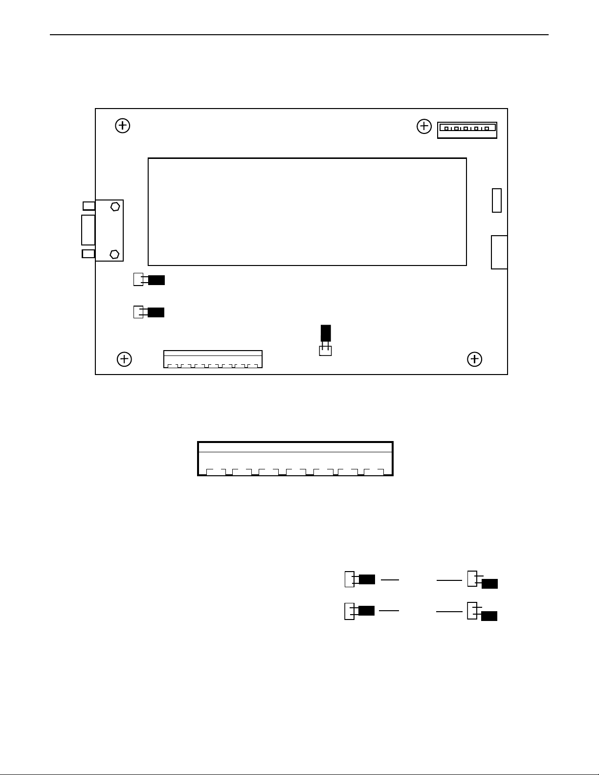
Printed Circuit Board Connector Locations.
12 3 4 5 67
4
+EXE +SEN +SIG CGND -SIG -SEN -EXE
Connector J4 Terminations.
For load cells without sense capability (4-wire), Jump 1
and Jump 2 must be shorted as shown in the illustration.
For load cells with sense capability (6-wire), Jump 1
and Jump 2 must be open.
4-Wire
Jumper Connections.
JUMP 1
JUMP 2
6-Wire
Jumper Connections.
Page 13
CD-11 Indicator
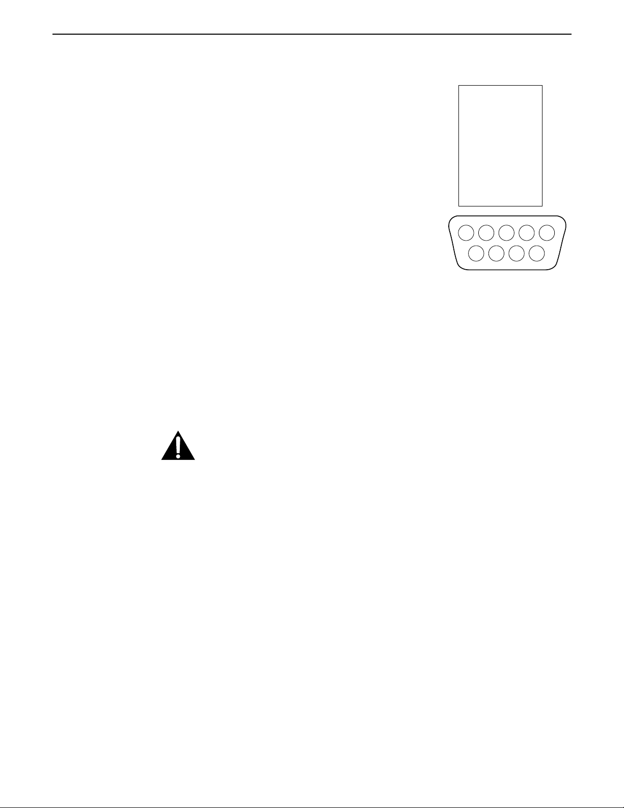
2.4 Connecting the RS232 Interface
CD-11 Indicators are equipped with a standard IBM
tional RS232 interface for communication with printers and computers. When
the Indicator is connected directly to a printer or a PC, displayed data can be
recorded at any time by simply pressing the Print/
Connecting the Indicator to a computer enables you to operate several functions of the Indicator from the computer, as well as receive data such as
displayed weight, weighing mode, stability status, etc.
TM
compatible, bi-direc-
Units
button.
EN-7
1 N/C
2 RXD
3 TXD
4 N/C
5 GND
6 N/C
7 N/C
8 N/C
9 N/C
Hardware
A 9-pin female “D” connector located on the left side of the indicator is provided for interfacing to other devices. Pin connections are shown in the adjacent illustration.
45
3
8
9
RS-232 Connector Pin Layout.
1
2
6
7
2.5 Connecting Power
The CD-11 Indicator may be operated using the AC Adapter supplied, or 6 Alkaline C-type batteries (not supplied).
2.5.1 AC Adapter
Connect the AC Adapter connector to the receptacle located at the right-hand side of the Indicator and plug the
adapter into a convenient outlet.
NOTICE:
The socket/outlet must be installed near
the equipment and shall be easily accessible.
2.5.2 Battery Installation
Open the battery cover on the bottom of the housing.
Insert 6 Alkaline C-type batteries into the two battery sleeves (3 in each sleeve) making sure the batteries are all
facing in the same direction.
Place the batteries into the two slots in the housing. Orient the batteries so that the positive (+) ends are against
the reeds and the negative (-) ends rest against the springs.
Page 14

EN-8
CD-11 Indicator
2.5.2 Battery Installation (Cont.)
NOTE: It is recommended that when the CD-11 is operated from batteries, the Auto-Off Timer feature be turned
on to extend battery life.
2.5.3 Switching On the Indicator
Once the Indicator and Scale Base are connected and installed, follow the setup procedure outlined below.
Power On/Off
With the Indicator connected to an appropriate power supply, press the ON/ZERO
performs a self-test, displays the software revision momentarily and then goes to a weighing mode.
At this point, the Indicator is on and ready for initial setup.
Off
button. The Indicator
Stabilization
Before initially using the Indicator, allow time for it to adjust to its new environment. Recommended warm up
period is five (5) minutes.
2.6 Initial Setup
The CD-11 Indicator is equipped with menus which permit certain functions to be locked out (not changed)
during operation. If locking out changes to the setup selections, access the CAL jumper located on the circuit
board following the setup procedure. Once all setup procedures are completed, reassemble the Indicator. For
first time setup, step through all menus and set the parameters as desired. As the last step, enter the CAL menu
and calibrate the system.
The Indicator has five menus; CAL (Calibration), SEtuP (Setup), rEAd (Read) , Print (Printing) and LOCSW
(Lockswitch) which are entered by pressing and holding the G/N/T/
releasing it. The display then switches to CAL.
To access the rest of the menus, the PRINT/
reached.
Units
button is repeatedly pressed until the desired menu is
Menu
button until MEnu is displayed, then
2.6.1 Control Functions
During setup, the following buttons are used.
Units
PRINT/
Change between menus horizontally or change sub-menu parameters.
Button
G/N/T/
Menu
Button
Press and hold to enter menu. Enters menu and steps through sub-menus vertically.
Tare Button
Change print interval settings.
Page 15
CD-11 Indicator
1
1
1
1
1
1
1
1
1
1
1
1
1
1
1
1
1
1
1
1
1
1
1
1
1
1
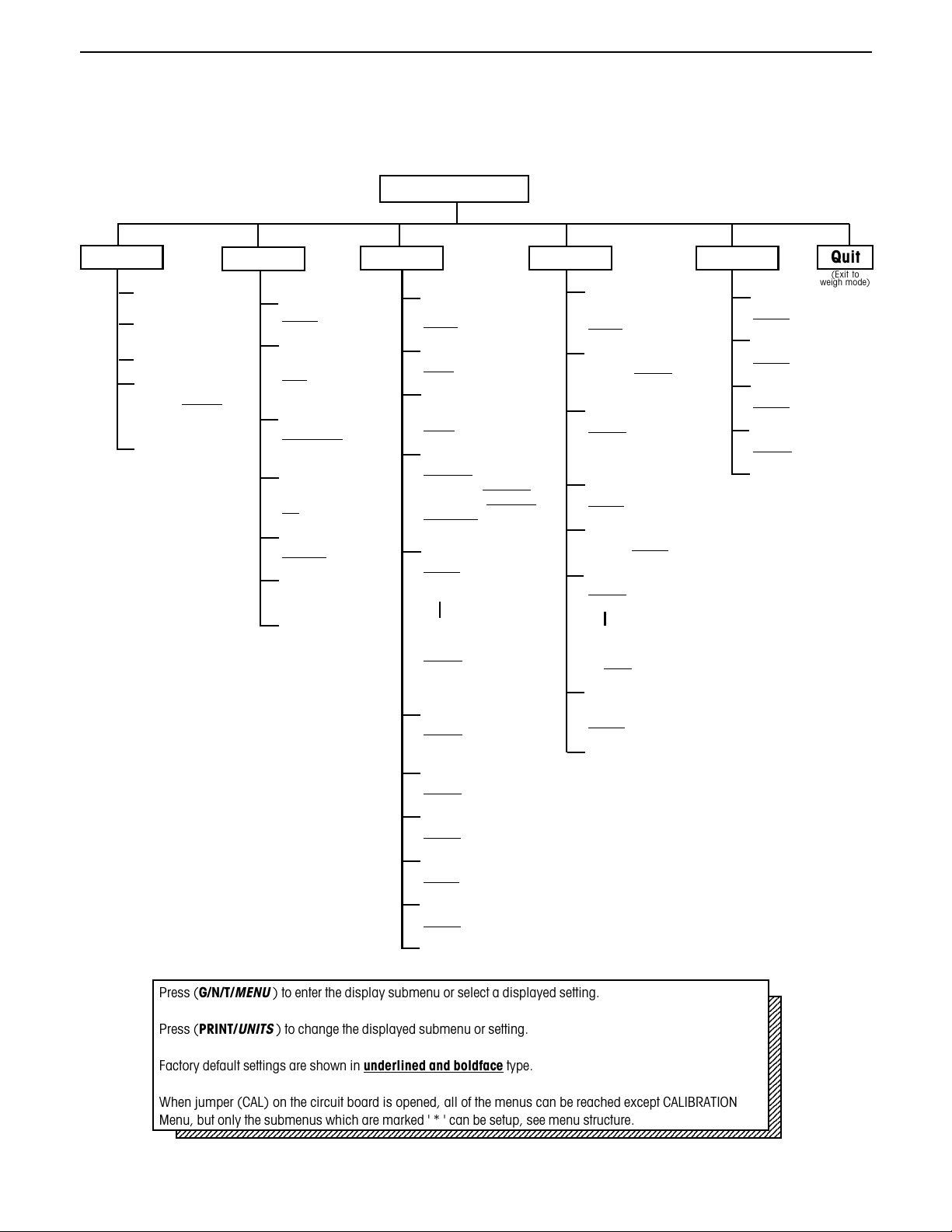
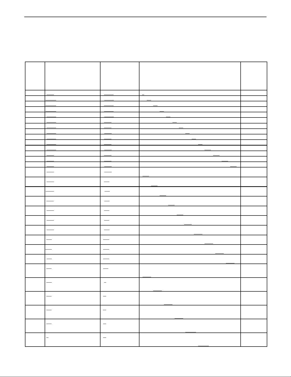
2.6.2 Menu Structure
The following table illustrates the menu structure in the CD-11 Indicator.
MAIN MENU
EN-9
CAL
CALIBRATION
SPAN Y
LIN Y
GEO (Value)
GEO 0...gEO 12...
GEO 31
Save Settings
SAVE
SEt uP rEAd Print LOCSW
Legal for Trade
LFtOn
,,
, LFtCan
,,
LFtOFF,
Zero (Range)
0 2 (2%),
0 18 (18%),
0 100 (100%)
Calibration Unit
CAL Un kg,
CAL Un lb
Full Scale
capacity
F 5, to....... F20000
Graduation Size
gd0.001, to ....gd 20
Calibration Point
CP 5, to....C20000
Save Settings
SAVE
* Reset rEAd menu to
factory defaults
rESEtn (no), rESEtY (yes)
* Averaging Level
AL LO, AL HI
* Stability Level
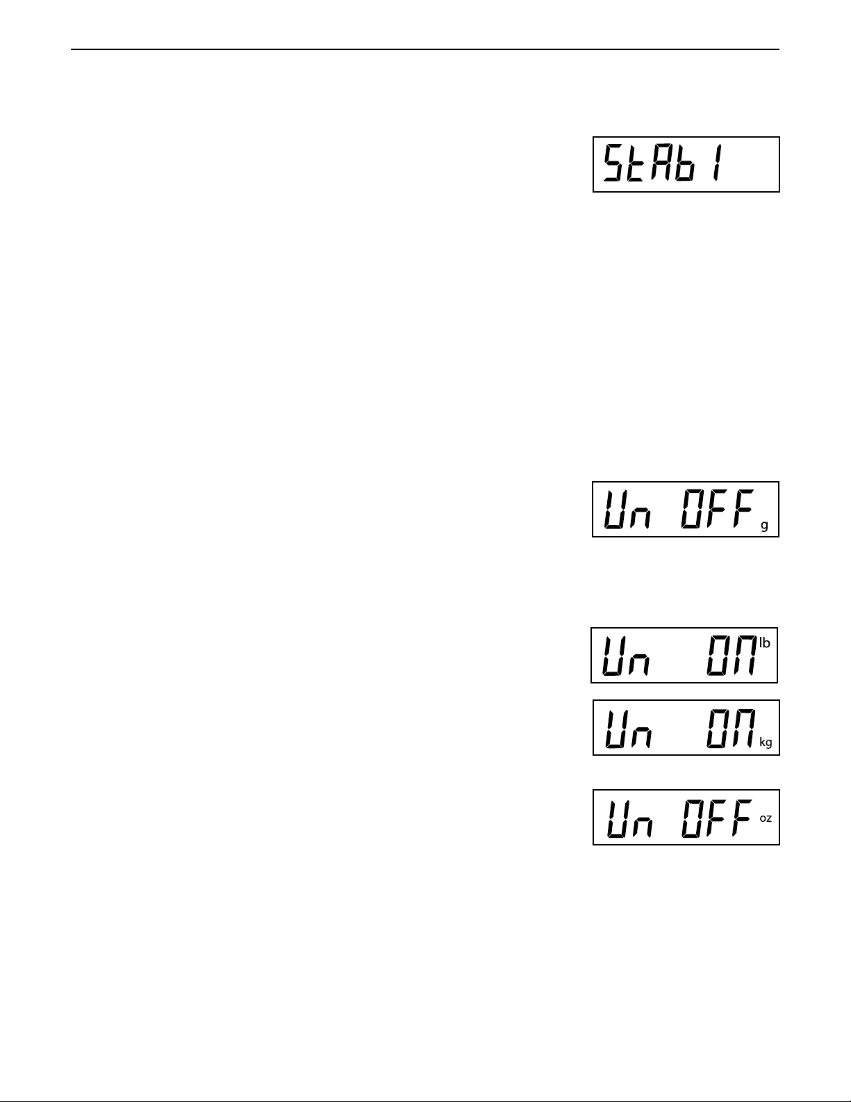
StAb0.5 (0.5d),
StAb1 (1d), StAb3 (3d)
*Unit of Measure
Un OFF g, Un On g,
Un OFF lb, Un On lb,
Un OFF kg, Un On kg,
Un OFF oz, Un On oz,
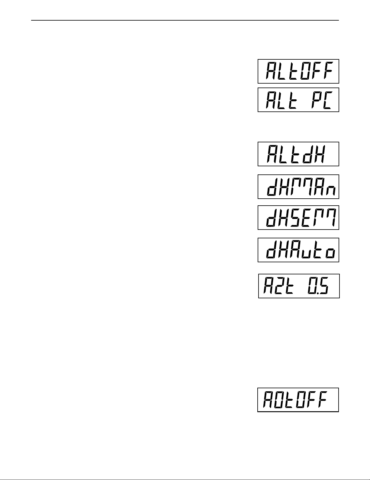
Alternate Mode
ALtOFF, (none)
ALtPC (Parts counting),
ALtdH (Display hold)
(If ALtdH is selected, set
display hold type)
dHMAn (manual),
dHSEM (semi-automatic),
dHAuto (Automatic)
*Auto Zero Tracking
AZt 0.5 (0.5d), AZt 1 (1d),
AZt 3 (3d)
*Auto Off Timer
AOtOFF, AOt On
* Reset Print menu to
Factory defaults
rESEtn (no), rESEtY (yes)
* Baud Rate
bd1200, bd2400, bd4800,
bd9600, bd19,200
*Parity
PAr nO (none),
PAr Odd (odd),
PAr E (even)
*Data Length
dAtA 7, dAtA 8
*Stop Bit
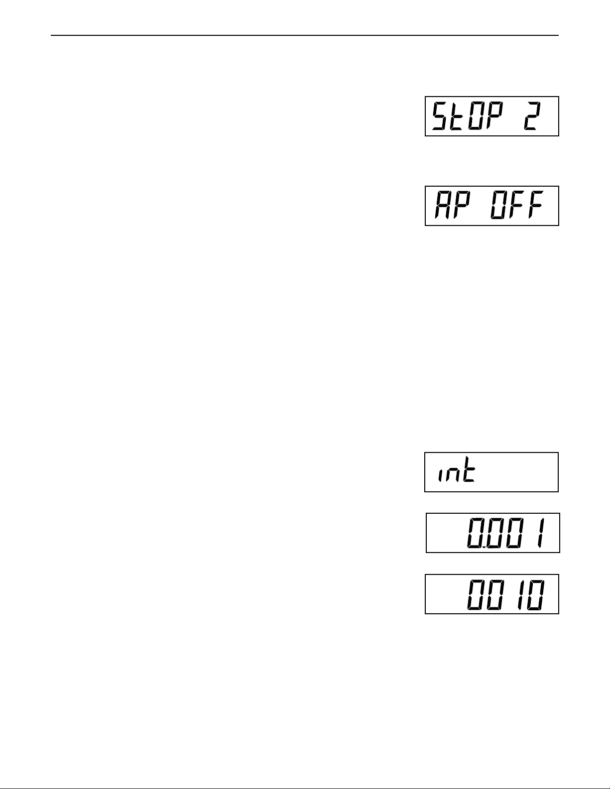
StOP 1, StOP 2
Auto Print mode
AP OFF, APCont, AP Int,
AP StbL
If AP Int is selected, set
Auto print interval
Int 0001 to 3600
Only print data when
stable
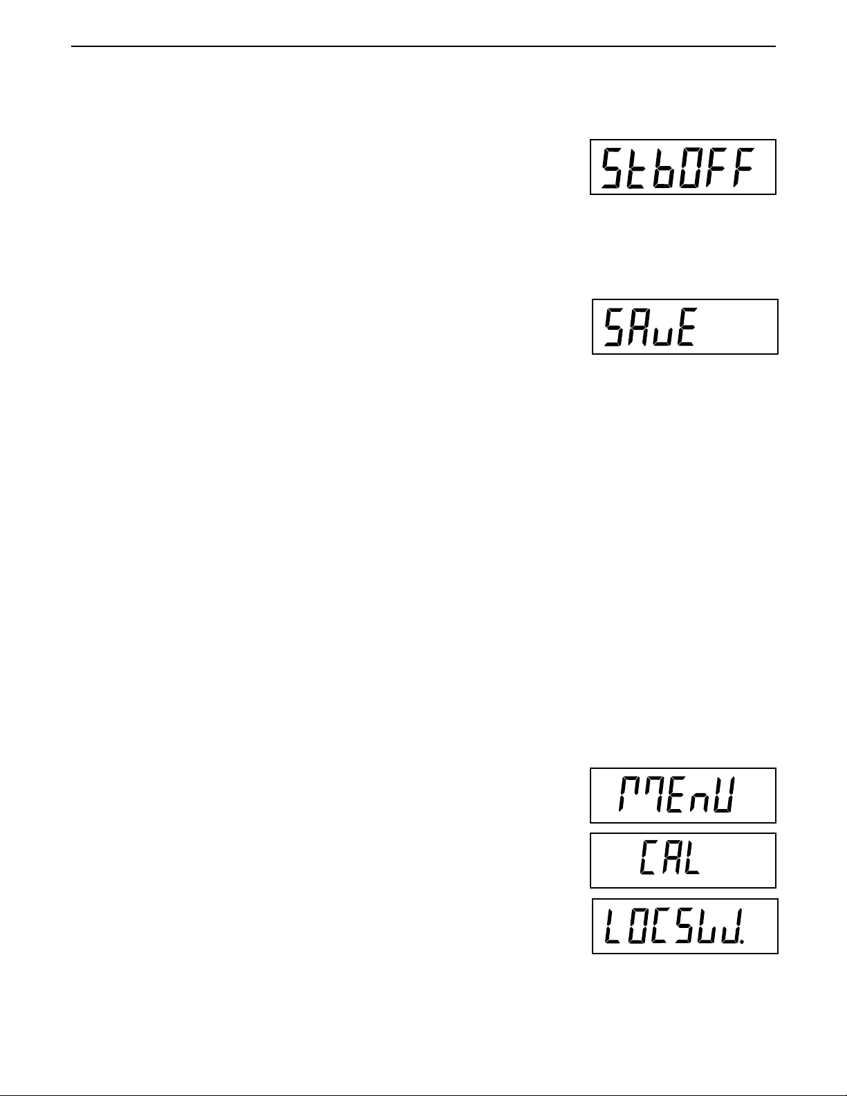
StbOFF, Stb On
* Save Settings
SAVE
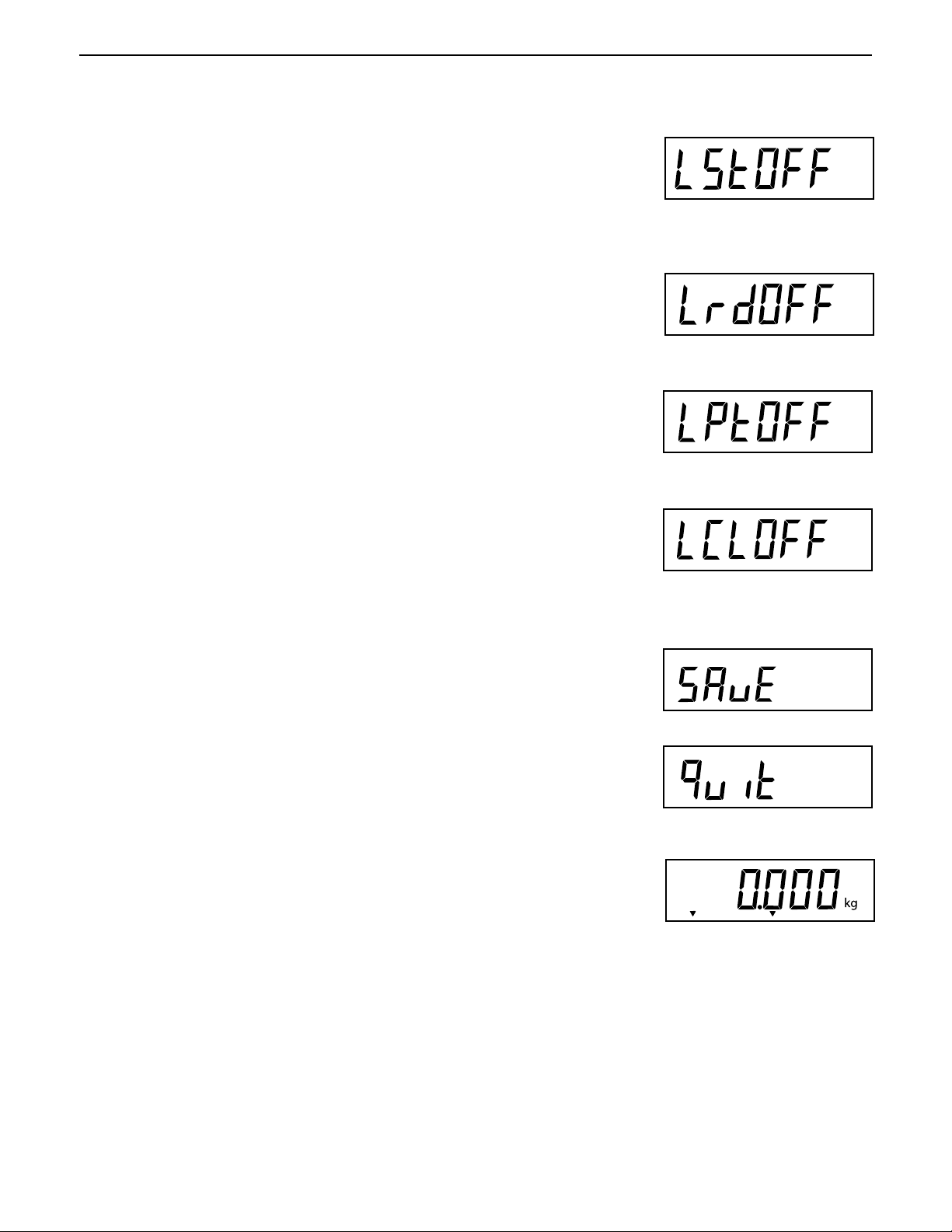
Quit
(Exit to
weigh mode)
Lock SEtUP menu
LStOFF, LST On
* Lock rEAd menu
LrdOFF, Lrd On
* Lock Print menu
LPtOFF, LPtOn
Lock CAL menu
LCLOFF, LCL On
* Save Settings
SAVE
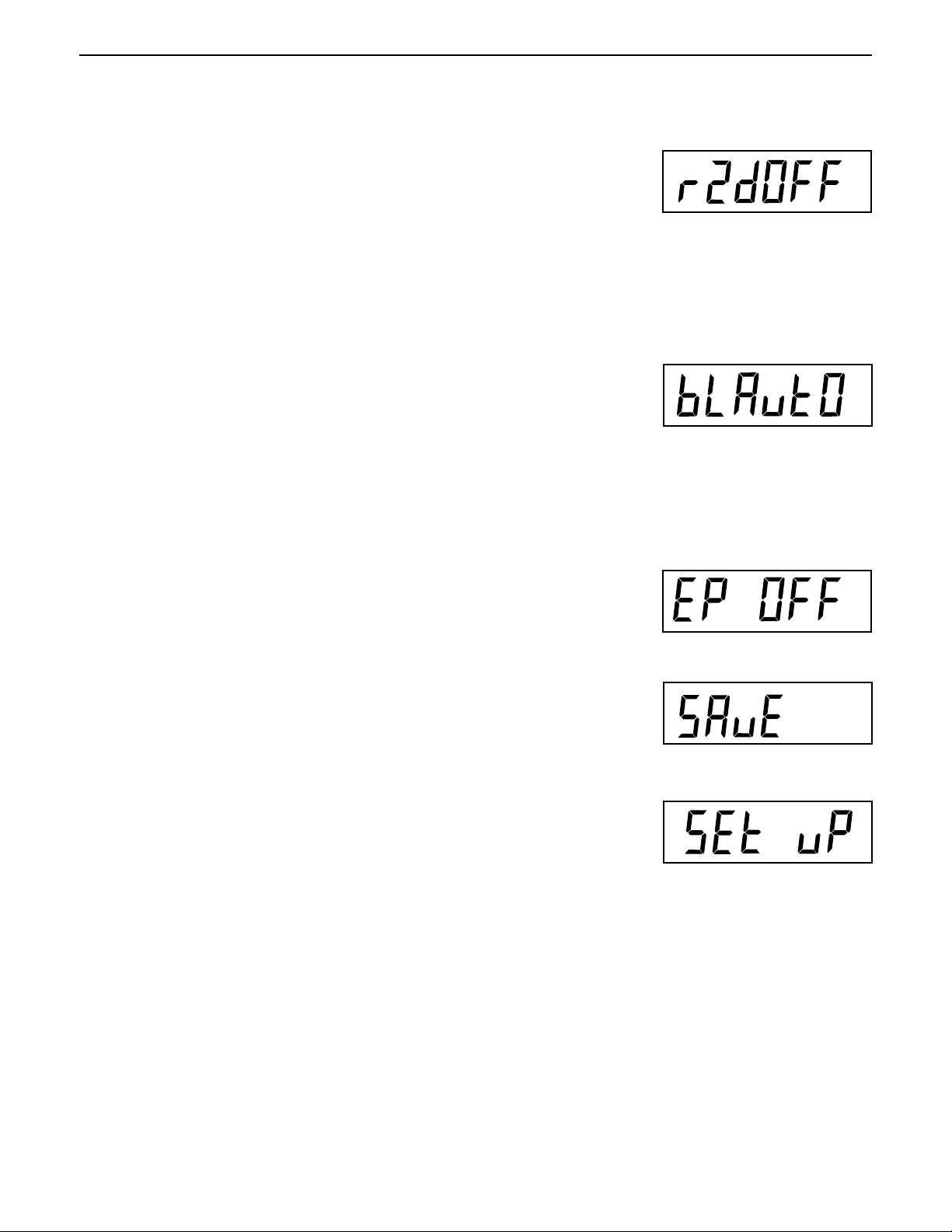
*Retain Zero Data
rZdOFF, rZd On
Backlight
bLAuto, bL On, bL OFF
EP (Service mode)
EP OFF or EP On
* Save Settings
SAVE
Press (G/N/T/
2345678901234567890123456789012123456789012345678901234567890121234567890123456789012345678901212345678901234567890
2345678901234567890123456789012123456789012345678901234567890121234567890123456789012345678901212345678901234567890
2345678901234567890123456789012123456789012345678901234567890121234567890123456789012345678901212345678901234567890
2345678901234567890123456789012123456789012345678901234567890121234567890123456789012345678901212345678901234567890
2345678901234567890123456789012123456789012345678901234567890121234567890123456789012345678901212345678901234567890
2345678901234567890123456789012123456789012345678901234567890121234567890123456789012345678901212345678901234567890
2345678901234567890123456789012123456789012345678901234567890121234567890123456789012345678901212345678901234567890
Press (PRINT/
2345678901234567890123456789012123456789012345678901234567890121234567890123456789012345678901212345678901234567890
2345678901234567890123456789012123456789012345678901234567890121234567890123456789012345678901212345678901234567890
2345678901234567890123456789012123456789012345678901234567890121234567890123456789012345678901212345678901234567890
2345678901234567890123456789012123456789012345678901234567890121234567890123456789012345678901212345678901234567890
2345678901234567890123456789012123456789012345678901234567890121234567890123456789012345678901212345678901234567890
2345678901234567890123456789012123456789012345678901234567890121234567890123456789012345678901212345678901234567890
2345678901234567890123456789012123456789012345678901234567890121234567890123456789012345678901212345678901234567890
Factory default settings are shown in underlined and boldface type.
2345678901234567890123456789012123456789012345678901234567890121234567890123456789012345678901212345678901234567890
2345678901234567890123456789012123456789012345678901234567890121234567890123456789012345678901212345678901234567890
2345678901234567890123456789012123456789012345678901234567890121234567890123456789012345678901212345678901234567890
2345678901234567890123456789012123456789012345678901234567890121234567890123456789012345678901212345678901234567890
2345678901234567890123456789012123456789012345678901234567890121234567890123456789012345678901212345678901234567890
2345678901234567890123456789012123456789012345678901234567890121234567890123456789012345678901212345678901234567890
2345678901234567890123456789012123456789012345678901234567890121234567890123456789012345678901212345678901234567890
When jumper (CAL) on the circuit board is opened, all of the menus can be reached except CALIBRATION
2345678901234567890123456789012123456789012345678901234567890121234567890123456789012345678901212345678901234567890
2345678901234567890123456789012123456789012345678901234567890121234567890123456789012345678901212345678901234567890
2345678901234567890123456789012123456789012345678901234567890121234567890123456789012345678901212345678901234567890
Menu, but only the submenus which are marked ' * ' can be setup, see menu structure.
2345678901234567890123456789012123456789012345678901234567890121234567890123456789012345678901212345678901234567890
2345678901234567890123456789012123456789012345678901234567890121234567890123456789012345678901212345678901234567890
MENU
) to enter the display submenu or select a displayed setting.
UNITS
) to change the displayed submenu or setting.
Page 16
EN-10
CD-11 Indicator
2.6.3 Load Cell Setup Parameters
Review the specifications of the scale base to be used with the Indicator. Make sure the settings you select in
the indicator are compatible with the scale base. The Capacity (full scale), readability (graduation size) and
calibration point (Span and Linearity) selections are shown in the setup table below.
Full Scale Graduation Size Graduation Size Span Calibration Point Linearity
Capacity with LFT OFF with LFT On and (CPxxxx) Calibration
(Fxxxxx) (gdxxxx) LFT CAn Points
( not user
selectable)
5 0.001, 0.002, 0.005 0.001, 0.002, 0.005 5 2 & 5
10 0.001, 0.002, 0.005, 0.01 0.002, 0.005, 0.01 5, 10 5 & 10
15 0.001, 0.002, 0.005, 0.01 0.005, 0.01 5, 10, 15 5 & 15
20 0.001, 0.002, 0.005, 0.01, 0.02 0.005, 0.01, 0.02 5, 10, 15, 20 10 & 20
25 0.002, 0.005, 0.01, 0.02 0.005, 0.01, 0.02 5, 10, 15, 20, 25 10 & 25
30 0.002, 0.005, 0.01, 0.02 0.01, 0.02 5, 10, 15, 20, 25, 30 15 & 30
40 0.002, 0.005, 0.01, 0.02 0.01, 0.02 5, 10, 15, 20, 25, 30, 40 20 & 40
50 0.005, 0.01, 0.02, 0.05 0.01, 0.02, 0.05 5, 10, 15, 20, 25, 30, 40, 50 25 & 50
60 0.005, 0.01, 0.02, 0.05 0.02, 0.05 5, 10, 15, 20, 25, 30, 40, 50, 60 30 & 60
75 0.005, 0.01, 0.02, 0.05 0.02, 0.05 5, 10, 15, 20, 25, 30, 40, 50, 60, 75 30 & 75
100 0.005, 0.01, 0.02, 0.05, 0.1 0.02, 0.05, 0.1 5, 10, 15, 20, 25, 30, 40, 50, 60, 75, 100 50 & 100
120 0.01, 0.02, 0.05, 0.1 0.05, 0.1 5, 10, 15, 20, 25, 30, 40, 50, 60, 75, 100, 120 60 & 120
150 0.01, 0.02, 0.05, 0.1 0.05, 0.1 5, 10, 15, 20, 25, 30, 40, 50, 60, 75, 100, 120, 150 75 & 150
200 0.01, 0.02, 0.05, 0.1, 0.2 0.05, 0.1, 0.2 5, 10, 15, 20, 25, 30, 40, 50, 60, 75, 100, 120, 150, 200 100 & 200
250 0.02, 0.05, 0.1, 0.2 0.05, 0.1, 0.2 5, 10, 15, 20, 25, 30, 40, 50, 60, 75, 100, 120, 150, 200, 120 & 250
300 0.02, 0.05, 0.1, 0.2 0.1, 0.2 5, 10, 15, 20, 25, 30, 40, 50, 60, 75, 100, 120, 150, 200, 150 & 300
400 0.02, 0.05, 0.1, 0.2 0.1, 0.2 5, 10, 15, 20, 25, 30, 40, 50, 60, 75, 100, 120, 150, 200, 200 & 400
500 0.05, 0.1, 0.2, 0.5 0.1, 0.2, 0.5 5, 10, 15, 20, 25, 30, 40, 50, 60, 75, 100, 120, 150, 200, 250 & 500
600 0.05, 0.1, 0.2, 0.5 0.2, 0.5 5, 10, 15, 20, 25, 30, 40, 50, 60, 75, 100, 120, 150, 200, 300 & 600
750 0.05, 0.1, 0.2, 0.5 0.2, 0.5 5, 10, 15, 20, 25, 30, 40, 50, 60, 75, 100, 120, 150, 200, 300 & 750
1000 0.05, 0.1, 0.2, 0.5, 1 0.2, 0.5, 1 5, 10, 15, 20, 25, 30, 40, 50, 60, 75, 100, 120, 150, 200, 500 & 1000
1200 0.1, 0.2, 0.5, 1 0.5, 1 5, 10, 15, 20, 25, 30, 40, 50, 60, 75, 100, 120, 150, 200, 600 & 1200
1500 0.1, 0.2, 0.5, 1 0.5, 1 5, 10, 15, 20, 25, 30, 40, 50, 60, 75, 100, 120, 150, 200, 750 & 1500
2000 0.1, 0.2, 0.5, 1, 2 0.5, 1, 2 5, 10, 15, 20, 25, 30, 40, 50, 60, 75, 100, 120, 150, 200, 1000 & 2000
2500 0.2, 0.5, 1, 2 0.5, 1, 2 5, 10, 15, 20, 25, 30, 40, 50, 60, 75, 100, 120, 150, 200, 1200 & 2500
3000 0.2, 0.5, 1, 2 1, 2 5, 10, 15, 20, 25, 30, 40, 50, 60, 75, 100, 120, 150, 200, 1500 & 3000
5000 0.5, 1, 2, 5 1, 2, 5 5, 10, 15, 20, 25, 30, 40, 50, 60, 75, 100, 120, 150, 200, 2500 & 5000
7500 0.5, 1, 2, 5 2, 5 5, 10, 15, 20, 25, 30, 40, 50, 60, 75, 100, 120, 150, 200, 3000 & 7500
10000 0.5, 1, 2, 5, 10 2, 5, 10 5, 10, 15, 20, 25, 30, 40, 50, 60, 75, 100, 120, 150, 200, 5000 & 10000
20000 1, 2, 5, 10, 20 5, 10, 20 5, 10, 15, 20, 25, 30, 40, 50, 60, 75, 100, 120, 150, 200, 10000 & 20000
250
250, 300
250, 300, 400
250, 300, 400, 500
250, 300, 400, 500, 600
250, 300, 400, 500, 600, 750
250, 300, 400, 500, 600, 750, 1000
250, 300, 400, 500, 600, 750, 1000, 1200
250, 300, 400, 500, 600, 750, 1000, 1200, 1500
250, 300, 400, 500, 600, 750, 1000, 1200, 1500, 2000
250, 300, 400, 500, 600, 750, 1000, 1200, 1500, 2000,
2500
250, 300, 400, 500, 600, 750, 1000, 1200, 1500, 2000,
2500, 3000
250, 300, 400, 500, 600, 750, 1000, 1200, 1500, 2000,
2500, 3000, 5000
250, 300, 400, 500, 600, 750, 1000, 1200, 1500, 2000,
2500, 3000, 5000, 7500
250, 300, 400, 500, 600, 750, 1000, 1200, 1500, 2000,
2500, 3000, 5000, 7500, 10000
250, 300, 400, 500, 600, 750, 1000, 1200, 1500, 2000,
2500, 3000, 5000, 7500, 10000, 20000
Page 17
CD-11 Indicator
2.6.4 Setup Menu
The CD-11 Indicator SEtuP Menu
parameters to match the Indicator. Do not attempt to calibrate the Indicator before initially setting up the
SEtuP Menu. All other menus should be entered and set up the first time the Indicator is used.
Procedure
must be entered the first time
the Indicator is used to set the scale base
EN-11
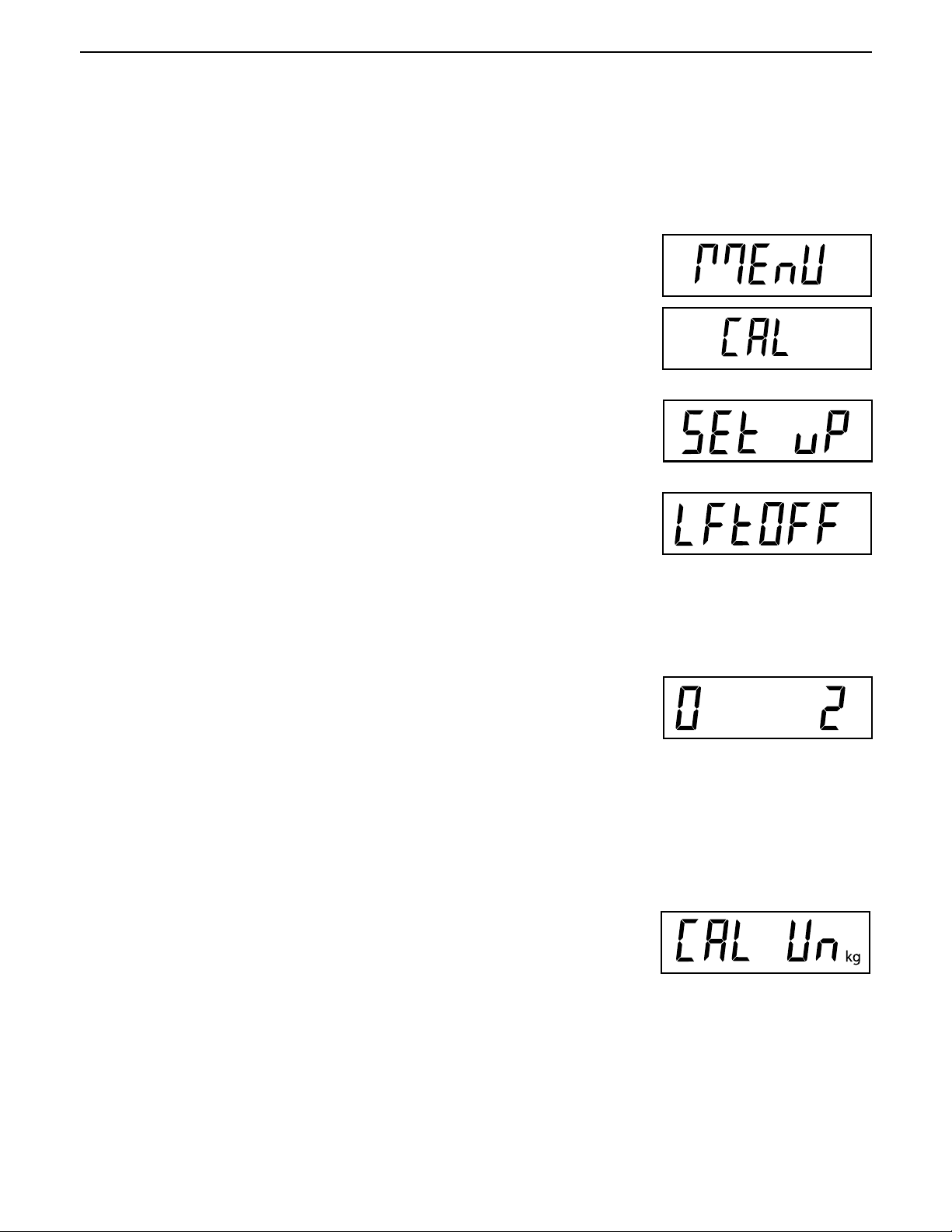
With the Indicator ON, press and hold the
displayed. When the G/N/T/
CAL jumper on the PC board is in place. When the CAL jumper is removed, the
Indicator will not permit calibration. This jumper should be in place initially.
Press the
Press the G/N/T/
are:
Press the PRINT/
Press G/N/T/
are:
2%: zero operating range is -2% to +2%.
18%: zero operating range is -2% to +18%,
100%: zero operating range is -2% to +100%.
PRINT/
Units
Menu
'ON' - LFT (Legal for Trade) is ON
'OFF' - LFT is OFF.
'CAn' - LFT is set for Canada
Units
Menu
button, 0 2 is displayed. This is the Zero setting. Selections
Menu
button is released, CAL is displayed if the
button, SEtuP is displayed.
button, LFtOFF is displayed. Legal for trade selections
button until desired LFT setting is reached.
G/N/T/
Menu
button until MEnU is
: :
NOTE
: If LFT is ON, only 2% and 18% are available.
: :
Press the PRINT/
Press the G/N/T/
unit setting. Selections are:
'lb' - calibration unit is lb
'kg' - calibration unit is kg.
Press the PRINT/
Units
button until desired zero setting is reached.
Menu
button, CAL Un kg is displayed. This is the calibration
Units
button until desired calibration unit setting is reached.
Page 18
EN-12
2.6.4 Setup Menu (Cont.)
Procedure
CD-11 Indicator
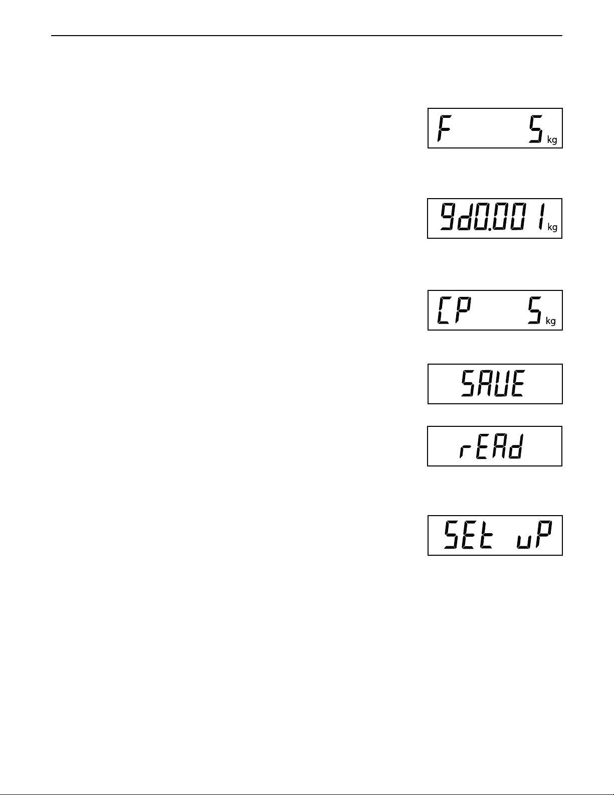
Press the G/N/T/
setting. xx= value last set. Available selections are are shown in the Setup
Table in section 2.6.3.
Press the PRINT/
Press the G/N/T/
size setting. Available selections are shown in the Setup Table in section
2.6.3.
Press the PRINT/
Press the G/N/T/
calibration point setting. The range is from 5kg/lb to 100% Full scale capacity.
Press the PRINT/
Press the G/N/T/
Menu
F xx is displayed
Units
button until desired capacity value is reached.
Menu
button, gd0.001 is displayed. This is the graduation
Units
button until desired graduation value is reached.
Menu
button, CP 5 kg is displayed. This is the full scale
Units
button until desired calibration value is reached.
Menu
button to end this block, SAVE is displayed.
..
. This is the full scale capacity
..
Press the G/N/T/
rEAD is displayed. The Indicator is now matched up with the scale base and
the Indicator parameters may now be set and calibrated.
Press the PRINT/
changes.
or
Menu
button to save the menu setup setting. The next menu
Units
button to return to the SEtuP menu without saving
Page 19
CD-11 Indicator
EN-13
2.6.5 Readout Menu
The Readout menu is used to adapt the Indicator to environmental conditions and set various features that
include: averaging level, stability level, measuring units, parts counting, display hold, auto zero tracking, timer,
retain zero data, backlight and a factory service mode. Review all of the settings available before proceeding.
Procedure
To select any of the items in the Readout menu, proceed as follows:
NOTE: If entering from the preceeding menu, disregard the first step.
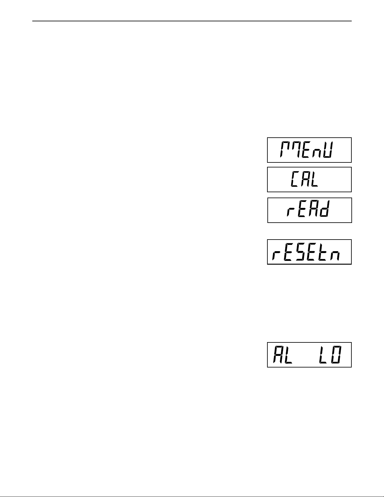
With the Indicator ON, press and hold the
displayed. When the G/N/T/
press the
Press the G/N/T/
rEAd menu to factory defaults.
Press the PRINT/
PRINT/
rESEtn = no, does not reset settings.
rESEty= yes, will reset the entire readout menu to factory defaults as
follows:
AL Lo, StAb 1, UnOff g, Un On kg, Un On Lb, Un Off oz, Alt Off, AZt 0.5,
AOt Off, rZd Off, bLAuto and EP OFF (service mode).
Units
button until rEAd is displayed.
Menu
button, rESEtn is displayed. This allows resetting the
Units
button for selections N or Y.
Menu
button is released, CAL is displayed, then
G/N/T/
Menu
button until MEnU is
AVERAGING LEVEL
Press the G/N/T/
settings. Selections are:
'Lo' - Less processing, less stability and faster stabilization time.
'Hi' - More processing, greater stability and slower stabilization time.
Averaging level compensates for vibration or excessive air currents on the
scale base. During operation, the Indicator continually takes weight readings
from the load cell. Successive readings are then digitally processed to achieve
a stabilized display. Using this feature specifies how much processing is
needed.
Press the PRINT/
Menu
button, AL LO is displayed. This is the averaging level
(This is the default setting)
Units
button until desired averaging level setting is reached.
Page 20
EN-14
2.6.5 Readout Menu (Cont.)
STABILITY
Press the G/N/T/
Selections are:
0.5d Smallest range: stability indicator is ON only when displayed
weight is within .5 division.
1d Normal stability (this is the default setting). Fixed for LFT.
3d Higher stability, less sensitive.
The stability range specifies the weighing results and must be within a preset
tolerance limit for a certain time to turn the stability indicator ON. When a
displayed weight changes beyond the allowable range, the stability indicator
turns OFF, indicating an unstable condition.
Menu
button, StAb1 is displayed. This is the stability setting.
CD-11 Indicator
Press the PRINT/
Units
button until desired stability setting is reached.
UNITS SELECTION
Press the G/N/T/
setting.
NOTE: g unit is not available for full scale capacities 100kg and above.
Press the PRINT/
setting.
Press the G/N/T/
setting. This will be displayed when CAL UNIT kg was selected. When lb was
selected as calibration unit, kg will display.
Press the PRINT/
Press the G/N/T/
setting.
Menu
button, Un OFF g is displayed. This is the unit gram
Units
button for selections ON or OFF. OFF is the default
Menu
button, Un ON lb is displayed. This is the unit pound
Units
button for selections ON or OFF. ON is the default setting.
Menu
button, Un OFF oz is displayed. This is the unit ounce
Press the PRINT/
setting.
Units
button for selections ON or OFF. OFF is the default
Page 21
CD-11 Indicator
2.6.5 Readout Menu (Cont.)
ALTERNATE MODE - not available with LFT ON or CAN
Press the G/N/T/
setting.
Selections are: OFF Standard weighing (this is the default setting)
Press the PRINT/
Alternate Mode enables either simple parts counting or display hold functions.
When ALtdH (display hold) is selected, a choice of manual, semi-automatic
or automatic settings are available. The alternate mode can be turned off so
that neither mode is available. It is not possible to have both modes activated
at the same time. For a complete description of alternate modes, refer to
Section 4 Operation.
Menu
button, ALtOFF is displayed. This is the alternate mode
PC Parts Counting
DH Display Hold - Man (manual)
Semi (semi-automatic)
Auto (automatic)
Units
button until desired alternate mode setting is reached.
EN-15
AUTO ZERO
Press the G/N/T/
Threshold setting. Selections are:
0.5d Sets threshold to 0.5 divisions. (this is the default setting)
1d Sets threshold to 1 division.
3d Sets threshold to 3 divisions.
Auto Zero minimizes the effects of temperature changes and small disturbances on the zero reading. The Indicator maintains the zero display until the
threshold is exceeded.
Press the PRINT/
reached.
Menu
button, AZt 0.5 is displayed. This is the Auto Zero
Units
button until desired auto zero threshold setting is
AUTO OFF TIMER
Press the G/N/T/
setting. When set ON, the Indicator will shut off automatically after 5 minutes
has elapsed on the condition that no button is pressed and the scale base
platform is stable during that period.
Press the PRINT/
Menu
button, AOtOFF is displayed. This is the Auto Off Timer
Units
button for selections ON or OFF. OFF is the default setting.
Page 22
EN-16
2.6.5 Readout Menu (Cont.)
RETAIN ZERO DATA
Press the G/N/T/
Data setting. When set On, the Indicator stores the current zero point and
restores it on the power-up.
button, Un rZdOFF is displayed. This is the Retain Zero
Menu
CD-11 Indicator
Press the PRINT/
setting.
button for selections ON or OFF. OFF is the default
Units
LCD BACK LIGHT
Press the G/N/T/
setting. Selections are:
Auto Turns off the backlight in 5 seconds (this is the default setting)
ON Backlight is on continuously
OFF Backlight does not turn on
Press the PRINT/
MENU
button, bLAutO is displayed. This is the LCD backlight
Units
button until desired LCD backlight setting is reached.
EP
This is a service function and is not a user-operated feature. OFF is the default
setting.
Not available with LFT ON or CAN.
SAVE
Press the G/N/T/
MENU
button to end this block, SAVE is displayed.
MENU
Press the G/N/T/
menu Print is displayed.
Press the PRINT/
changes.
NOTE: If initial setup, go to the next paragraph. To exit from the SEtuP menu,
press the PRINT/
the G/N/T/
MENU
button to save the readout menu settings. The next
or
Units
button to go back to the SEtuP menu without saving
Units
button to skip to PRINT then to LOCKSW, then Quit. Press
button to go back to the weighing mode.
Page 23
CD-11 Indicator
EN-17
2.6.6 Print Menu
The Print menu provides data communication settings. It contains 9 submenus: Reset, Baud rate, Parity, Data
Length, Stop Bits, Auto Print, Interval, Stable and Save.
Procedure
To select any of the items in the Print menu, proceed as follows:
NOTE: If entering from the preceeding menu, disregard the first step.
With the Indicator ON, press and hold the
displayed. When the G/N/T/
press the
Press the G/N/T/
Print menu to factory defaults. rESETn = no, does not reset settings.
rESETy=yes, will reset the entire Print menu to factory defaults as follows:
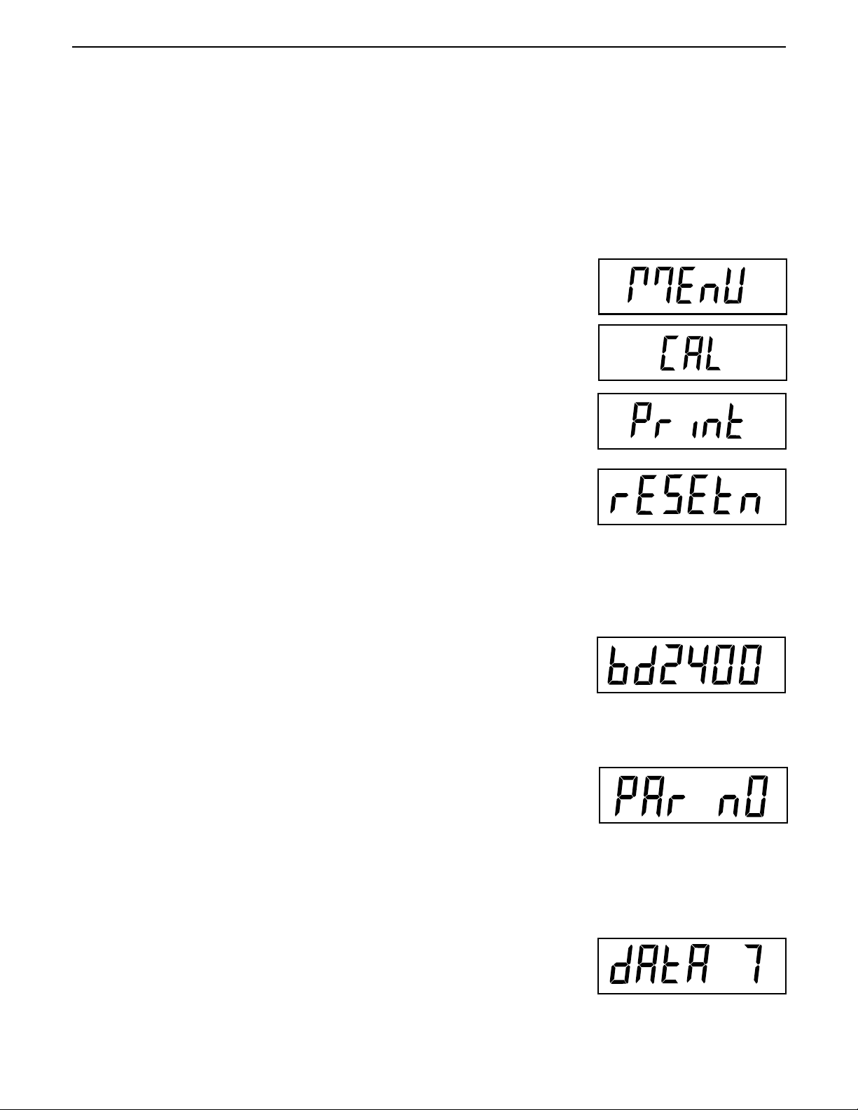
Press the PRINT/
Press the G/N/T/
Selections are: 1200, 2400, 4800, 9600 and 19,200. 2400 is the default
setting.
PRINT/
Baud rate =2400, parity =none, data length=7, stop bit=2, Auto
Print=AP OFF, if interval is selected=.0001, Stable Print= StbOFF.
Units
button until Print is displayed.
Menu
button, rESEtn is displayed. This allows resetting the
Units
button for selections N or Y.
Menu
button, bd2400 displayed. This is the baud rate setting.
Menu
button is released, CAL is displayed, then
G/N/T/
Menu
button until MEnU is
Press the PRINT/
Press the G/N/T/
Selections are:
PAr nO=none (this is the default setting)
PAr Odd=odd
PAr E=even
Press the PRINT
Press the G/N/T/
setting.
Press the PRINT/
dAtA 7.
Units
button until the desired baud rate is reached.
Menu
button, PAr nO is displayed. This is the parity bit setting.
Units
button until desired parity bit setting is reached.
Menu
button, dAtA 7 is displayed. This is the data length
Units
button for selections dAtA 7 or dAtA 8. Default setting is
Page 24
EN-18
2.6.6 Print Menu (Cont.)
CD-11 Indicator
Press the G/N/T/
Press the PRINT/
StOP 2.
Menu
button, StOP 2 is displayed. This is the stop bit setting.
Units
button for selections StOP 1 or StOP 2. Default setting is
AUTO PRINT
Press the G/N/T/
This is the Auto print setting which enables data to a printer or PC to be printed
automatically. Selection are:
OFF (this is the default setting)
Cont Prints data continuously
Int Prints data on user selected intervals
Stbl Print first stable non-zero value after each change in weighing
value.
Press the PRINT/
Menu
button, AP OFF is displayed.
Units
button until desired auto print setting is reached.
INTERVAL PRINTING
When interval has been selected in the previous step, an interval from 1 to
3600 seconds can be set. If Interval was not selected, this submenu does not
appear.
Press the G/N/T/
display appears which allows the interval time in seconds to be set.
Pressing the PRINT/
the TARE button increments the active digit from 0 to 9.
Sample at right indicates 10 seconds.
NOTE: 0000 not valid.
Menu
button, int is displayed. After a few seconds, a second
Units
button advances the zero from left to right. Pressing
Page 25
CD-11 Indicator
2.6.6 Print Menu (Cont.)
STABLE
Press the G/N/T/
When set to Stb ON, allows only stable weight values to be printed. When set
Stb OFF, prints immediate value with stability indication. In LFT, fixed to Stb ON.
Menu
button, Stb OFF is displayed.
EN-19
Press the PRINT/
OFF.
Units
button for selections Stb ON or Stb OFF. Default setting is
SAVE
Press the G/N/T/
Press the G/N/T/
LOCSW is displayed.
Press the PRINT/
NOTE:If initial setup, go to the next paragraph. To exit from the SEtuP, press
the PRINT/
button to go back to the weighing mode.
Menu
Menu
Units
button to skip to LOCKSW, then Quit. Press the G/N/T/
button to end this block, SAVE is displayed.
button to save the Print menu settings. The next menu
or
Units
button to go back to the rEAd menu without saving.
Menu
2.6.7 Lockout Menu
The Lockout menu (LOCSW) allows the user to lock and unlock the settings in the CAL, SEtuP, rEAd, and Print
menus to prevent tampering or accidental changes. When used in conjunction with the Lock Switch (jumper)
on the printed circuit board, the CAL, SEtuP, rEAd and Print menus can be read only and not changed.
Procedure
To select any of the items in the LOCSW menu, proceed as follows:
NOTE: If entering from the preceeding menu, disregard the first step.
With the Indicator ON, press and hold the
displayed. When the G/N/T/
press the PRINT/
Units
Menu
button is released, CAL is displayed, then
button until LOCSW is displayed.
G/N/T/
Menu
button until MEnU is
Page 26
EN-20
*
2.6.7 Lockout Menu (Cont.)
CD-11 Indicator
Press the G/N/T/
Menu
button, LStOFF is displayed. This permits locking the
SEtuP menu. LStOFF is unlocked, LSt On is read only (locked). This menu is
hidden if the CAL jumper is off.
Press the
Press the G/N/T/
PRINT/
Units
Menu
button for selections LSt ON or LStOFF.
button, LrdOFF displayed. This permits locking the rEAd
menu. LrdOFF is unlocked, Lrd On is read only (locked).
Press the PRINT/
Press the G/N/T/
Units
button for selections Lrd On or LrdOFF.
Menu
button, LPtOFF is displayed. This permits locking the
Print menu. LPtOFF is unlocked, LPtOn is read only (locked).
Press the PRINT/
Press the G/N/T/
Units
Menu
button for selections LPtOn or LPtOFF.
button, LCLOFF is displayed. This permits locking the
Calibration menu. LCLOFF is unlocked, LCL On is read only (locked). This
menu is hidden if the CAL jumper is off.
Press the PRINT/
Press the G/N/T/
Press the G/N/T/
Units
Menu
Menu
button for selections LCL On or LCLOFF.
button to end this block, SAVE is displayed.
button to save the lockout menu settings. The next
menu Quit is displayed.
or
Press the PRINT/
After saving the lockout menu settings, press the PRINT/
CAL or press the G/N/T/
Units
button to go back to the lockout menu without saving.
Units
button to go to
Menu
button to return to a weighing mode.
NOTE: At this point, the Indicator must be calibrated and the jumper removed
from the CAL connector in order to lock the menus. The top cover of the Indicator should be free to gain access to the CAL jumper.
>0<>0<
>0<
>0<>0<
Stable
Gross
Brutto
Page 27
CD-11 Indicator
EN-21
3. CALIBRATION AND SEALING
Model CD-11 Indicator requires span calibration before using. Span calibration ensures that the Indicator
reads correctly within specifications. For best results, calibrate at or near full capacity. Calibration unit can be
set to either kg or lb.
NOTE: When the Indicator is used in Legal for Trade or legally controlled applications, the calibration
menu is locked out and is not accessible.
tion.
Before beginning calibration, make sure masses are available. If you begin calibration and realize calibration
masses are not available, exit the menu. The Indicator will retain previously stored calibration data. Calibration should be performed as necessary to ensure accurate weighing. Masses required to perform the procedures should be in compliance with the requirements of the scale base being used with the Indicator.
You have a choice of either span or linearity calibration. Span calibration checks zero and full span calibration points. Linearity calibration checks zero, mid span and full span points.
Procedure
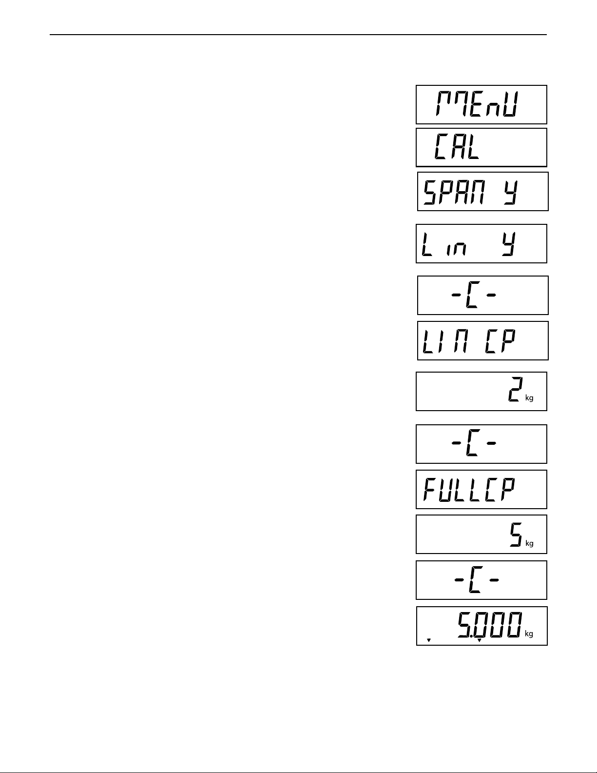
SPAN CALIBRATION
With the Indicator ON, press and hold the
displayed. When the
G/N/T/
Menu
button is released, CAL is displayed.
This is to prevent unauthorized personnel from changing calibra-
G/N/T/
Menu
button until MEnU is
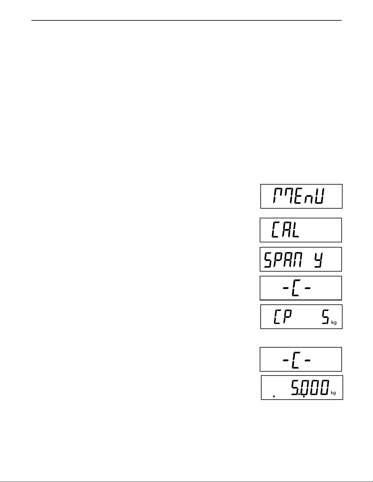
Press the G/N/T/
Press the G/N/T/
during this period as it establishes a zero point. After a few seconds, the
requested weight value is displayed. The sample illustration indicates a 5kg
weight value (Cal Point CP was set for 5kg).
Place the indicated mass on the platform. Keep the platform stable during this
period.
Press the G/N/T/
reading and then displays the weight of the mass.
If the calibration was successful, the calibration weight is displayed and the
calibration data is saved automatically. If unsuccessful, refer to the troubleshooting section.
Remove calibration masses from the platform.
NOTE: If the Indicator is to be used for legal for trade or legally controlled applications, it must be calibrated and
the jumper removed from the CAL connector in order to lock the menus. The top cover of the Indicator should be
free to gain access to the CAL jumper. Refer to section 3.1 for sealing for legal for trade use.
Menu
button, SPAN Y is displayed.
Menu
button, -C- is displayed. The scale base
Menu
button, -C- is displayed while the Indicator stores the
MUST
be stable
Stable
Gross
Brutto
Page 28
EN-22
Procedure
LINEARITY CALIBRATION
With the Indicator ON, press and hold the
displayed. When the
G/N/T/
Menu
button is released, CAL is displayed.
button G/N/T/
Menu
CD-11 Indicator
until MEnU is
Press the G/N/T/
Press the PRINT/
Press the G/N/T/
Menu
button, SPAN Y is displayed.
Units
button, Lin Y is displayed.
Menu
button, -C- is displayed. The scale base
MUST
be stable
during this period as it establishes a zero point. After a few seconds, the display flashes LIN CP twice and the requested weight value is displayed. The
sample illustration indicates a 2kg center point for a 5kg scale.
Place the indicated mass on the platform. Keep the platform stable during this
period.
Press the G/N/T/
button, -C- is displayed. The scale base
MUST
be stable
Menu
during this period as it establishes a center point. After a few seconds, the display flashes FULLCP twice and the requested weight value is displayed.
Menu
Place the indicated mass on the platform and press the G/N/T/
button -C-
is displayed.
If linearity calibration was successful, the calibration weight is displayed and
the calibration data is saved automatically. If unsuccessful, refer to the troubleshooting section.
Stable
Gross
Brutto
Remove calibration masses from platform.
NOTE: If the Indicator is to be used for legal for trade or legally controlled applications, it must be calibrated
and the jumper removed from the CAL connector in order to lock out the menus. The top cover of the Indicator
should be free to gain access to the CAL jumper. Refer to section 3.1 for sealing for legal for trade use.
Page 29
CD-11 Indicator
GEOGRAPHICAL FACTOR (For Europe Only)
EN-23
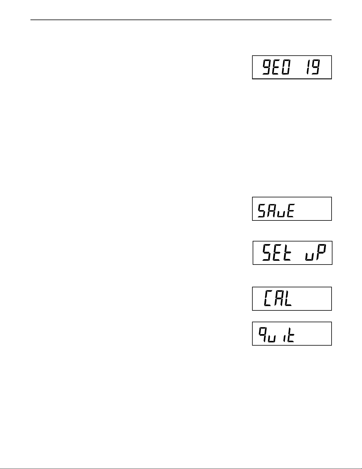
Press the G/N/T/
graphical adjustment value.
The geo factor includes settings from 0 to 31 and is used to compensate for
varying gravity at different geographical areas (complete geographical adjustment settings are listed in the following table).
Only an authorized manufacturer’s representative or certified verification
Changing the geographical setting alters the calibration values.
Press the Print/
reached. The factory default setting is gEO 19
SAVE
Press the G/N/T/
Menu
button, gEO 19 is displayed. This is the current geo-
NOTE:
personnel may make these changes.
Units
button until the desired geographical adjustment value is
Menu
button to end this block, SAVE is displayed.
Press the G/N/T/Menu button to save the geographical factor setting. The next
menu SEt uP is displayed.
or
Units
Press the Print/
changes to the geographical setting.
QUIT
To exit from the CAL menu, press the Print/
Then press the G/N/T/
button to go back to the CAL menu without saving
Units
button to advance to Quit.
Menu
button to go back to the weighing mode.
Page 30

EN-24
CD-11 Indicator
GEOGRAPHICAL FACTOR (cont.)
GEOGRAPHICAL ADJUSTMENT VALUES
Elevation above sea level in meters
0 325 650 975 1300 1625 1950 2275 2600 2925 3250
Geographical latitude in 325 650 975 1300 1625 1950 2275 2 6 00 2925 3250 3575
the northern or southern Elevation above sea level in feet
hemisphere in degrees 0 106 0 2130 3200 4260 5330 6400 7460 8530 9600 10660
and minutes 1060 2130 3200 4260 5330 6400 7460 8530 9600 10660 11730
0°0'-5°46’ 5 4 4 3 3 2 2 1 1 0 0
5°46'-9°52’ 5 5 4 4 3 3 2 2 1 1 0
9°52'-12°44’ 6 5 5 4 4 3 3 2 2 1 1
12°44'-15°6’ 6 6 5 5 4 4 3 3 2 2 1
15°6'-17°10’ 7 6 6 5 5 4 4 3 3 2 2
17°10'-19°2’ 7 7 6 6 5 5 4 4 3 3 2
19°2'-20°45’ 8 7 7 6 6 5 5 4 4 3 3
20°45'-22°22’ 8 8 7 7 6 6 5 5 4 4 3
22°22'-23°54’ 9 8 8 7 7 6 6 5 5 4 4
23°54'-25°21’ 9 9 8 8 7 7 6 6 5 5 4
25°21'-26°45’ 10 9 9 8 8 7 7 6 6 5 5
26°45'-28°6’ 10 10 9 9 8 8 7 7 6 6 5
28°6'-29°25’ 11 10 10 9 9 8 8 7 7 6 6
29°25'-30°41’ 11 11 10 10 9 9 8 8 7 7 6
30°41'-31°56’ 12 11 11 10 10 9 9 8 8 7 7
31°56'-33°9’ 12 12 11 11 10 10 9 9 8 8 7
33°9'-34°21’ 13 12 12 11 11 10 10 9 9 8 8
34°21' - 35° 31' 13 13 12 12 11 11 10 10 9 9 8
35°31' - 36° 41' 14 13 13 12 12 11 11 10 10 9 9
36°41' - 37° 50' 14 14 13 13 12 12 11 11 10 10 9
37°50' - 38° 58' 15 14 14 13 13 12 12 11 11 10 10
38°58' - 40° 5' 15 15 14 14 13 13 12 12 11 11 10
40° 5' - 41° 12' 16 15 15 14 14 13 13 12 12 11 11
41°12' - 42° 19' 16 16 15 15 14 14 13 13 12 12 11
42°19' - 43° 26' 17 16 16 15 15 14 14 13 13 12 12
43°26' - 44° 32' 17 17 16 16 15 15 14 14 13 13 12
44°32' - 45° 38' 18 17 17 16 16 15 15 14 14 13 13
45°38' - 46° 45' 18 18 17 17 16 16 15 15 14 14 13
46°45' - 47° 51' 19 18 18 17 17 16 16 15 15 14 14
47°51' - 48° 58' 19 19 18 18 17 17 16 16 15 15 14
48°58' - 50° 6' 20 19 19 18 18 17 17 16 16 15 15
50° 6' - 51° 13' 20 20 19 19 18 18 17 17 16 16 15
51°13' - 52° 22' 21 20 20 19 19 18 18 17 17 16 16
52°22' - 53° 31' 21 21 20 20 19 19 18 18 17 17 16
53°31' - 54° 41' 22 21 21 20 20 19 19 18 18 17 17
54°41' - 55° 52' 22 22 21 21 20 20 19 19 18 18 17
55°52' - 57° 4' 23 22 22 21 21 20 20 19 19 18 18
57° 4' - 58° 17' 23 23 22 22 21 21 20 20 19 19 18
58°17' - 59° 32' 24 23 23 22 22 21 21 20 20 19 19
59°32' - 60° 49' 24 24 23 23 22 22 21 21 20 20 19
60°49' - 62° 9' 25 24 24 23 23 22 22 21 21 20 20
62° 9' - 63° 30' 25 25 24 24 23 23 22 22 21 21 20
63°30' - 64° 55' 26 25 25 24 24 23 23 22 22 21 21
64°55' - 66° 24' 26 26 25 25 24 24 23 23 22 22 21
66°24' - 67° 57' 27 26 26 25 25 24 24 23 23 22 22
67°57' - 69° 35' 27 27 26 26 25 25 24 24 23 23 22
69°35' - 71° 21' 28 27 27 26 26 25 25 24 24 23 23
71°21' - 73° 16' 28 28 27 27 26 26 25 25 24 24 23
73°16' - 75° 24' 29 28 28 27 27 26 26 25 25 24 24
75°24' - 77° 52' 29 29 28 28 27 27 26 26 25 25 24
77°52' - 80° 56' 30 29 29 28 28 27 27 26 26 25 25
80°56' - 85° 45' 30 30 29 29 28 28 27 27 26 26 25
85°45' - 90° 00' 31 30 30 29 29 28 28 27 27 26 26
Page 31

CD-11 Indicator
EN-25
3.1 Legal for Trade (LFT) Operation and Sealing
Before this product can be used in legal-for-trade or legally controlled applications, it must be inspected in
accordance with local weights and measures or approval agency regulations. It is the responsibility of the
purchaser to ensure that all pertinent legal requirements are met. Please contact your local weights and measures office or authorized manufacturer's representative for further details.
Legal for Trade (LFT) operation is possible through a software controlled
LOCSW menu which can be set to lock out the CAL, SEtuP, rEAd, and Print
menus by setting the lock settings to ON. When the menus have been locked
and the Indicator has been calibrated, the Indicator can be used to operate in
a legal for trade application after sealing. The software settings work in
conjunction with a Lock Switch ( CAL jumper) located on the PC board. The
Indicator MUST
be calibrated prior to performing this procedure.
Procedure
Perform the procedure in section 2.6.7 and set all menu items ON. This
effectively locks all menus from being changed but can be viewed.
Remove the front cover from the Indicator to expose the PC board and tilt it
back. Be careful as the cover is connected to the PC board by a flexible
cable.
Refer to the illustrations on the right and note the position of the CAL jumper.
The first illustration shows the jumper in place. To lock out the menus,
remove the jumper and position it on one pin as shown in the second
illustration. This removes the jumper and stores it in the event it has to be repositioned.
1
J5
5
6
9
1
J3
JUMP 1
JUMP 2
J4
1234 567
+EXE +SEN +SIG CGND -SIG -SEN -EXE
DISPLAY
CAL
J6
J7
PC Board Connections.
J4
1234 567
+EXE +SEN +SIG CGND -SIG -SEN -EXE
CAL
CAL Jumper Shown in Stored or
ON Position.
5
3
2
1
4
1
Replace the four cover screws and one sealing screw.
Replace the batteries and battery cover.
After the Indicator has been tested and found to comply with local applicable
regulations by local approving personnel, it may be sealed as follows:
LEAD AND WIRE SEAL
Replace the pan head screw with the hex socket security screw and washer in
the plastic bag containing the accessories. See illustration at right. Place
wire seal through the hole as shown and compress lead seal in place.
PAPER SEAL
If an audit trail or paper seal will be used, install the pan head screw to the
case and place seal over the screw area. The sealing area is located on the
bottom of the case in a recessed area.
LEAD SEAL
HEX SOCKET HEAD SCREW
PAPER SEAL
PAPER SEAL
Sealing Methods
Page 32

EN-26
*
*
CD-11 Indicator
4. OPERATION
Before using the Indicator, make sure it has been properly set up and calibrated. Refer to Sections 2 and 3 and
the Overview of Controls and Indicator Functions to review settings.
4.1 Turning On Indicator
Press the ON ZERO/
Off
button until the LCD display
appears. The display momentarily displays segment
check, the software version of the Indicator and then goes
into a weighing mode. The weighing mode and decimal
point position may be different depending on the setup of
the Indicator.
4.2 Turning Off Indicator
To turn the Indicator off, press and hold the ON ZERO/
Stable Display
ON/ZERO
Off
Hold
2II
PCS Gross
button until OFF is displayed.
4.3 Zero Operation
Press the ON ZERO/
by indicating the selected measuring unit followed by a zeroed display.
NOTE: Stable cursor must be lit to accept zero operation.
Place item to be weighed on the scale platform. The display indicates a sample
of 5kg, gross weight.
Off
button to zero the Indicator. The display acknowledges
Net Tare
Brutto
PRINT
8QLWV
>0<>0<
>0<
>0<>0<
Stable Gross
G/N/T
0HQX
TARE
Brutto
Stable
Gross
Brutto
4.4 Tare Operation
When weighing material or objects that must be held in a container, taring
stores the container weight in the Indicator’s memory. To store the container
weight, proceed as follows:
Place the container on the scale. Sample shown is 2kg.
Press the TARE button. Scale is tared and shows Net weight.
Stable
NOTE: Stable cursor must be lit to accept tare operation.
If the tare weight is removed from the scale, the Net weight is displayed as a
negative value
Stable
Stable
Gross
Brutto
Net
Net
Page 33

CD-11 Indicator
*
4.5 Gross/Net/Tare Recall Operation
When a container has been placed on the platform and tared, it's weight is
stored in memory. Adding material to the container is shown as NET weight.
The gross weight is a combination of the tared weight and the material. The
G/N/T/
Repeatedly press the G/N/T/
readings. The sample illustrations indicate a tare weight of 2kg simulating a
container, a net weight of 3kg which would be the material in the container
and a gross weight of 5kg which is the total weight of the container and
material. After a few seconds, the display will return to a NET weight.
Menu
button allows switching between GROSS, NET and TARE weights.
Menu
button to cycle through Gross, Tare and Net
Stable
Stable
Gross
Brutto
EN-27
Tare
4.6 Clear Tare Operation
To clear the tared weight stored in memory, proceed as follows:
With no load on the scale base, press the TARE button.
4.7 Unit Switch Operation
To switch measuring units, proceed as follows:
Press and hold PRINT/
ing unit. Depending on which units are enabled in the menu, you have a
choice of g, lb, kg or oz. The display sample indicates 3kg load changed to
lbs.
Units
button until display changes to selected measur-
>0<>0<
>0<
>0<>0<
Stable
Stable
Stable
Stable
Gross
Brutto
Gross
Brutto
Net
Net
Stable
Gross
Brutto
Page 34

EN-28
*
4.8 Parts Counting Operation
CD-11 Indicator
Parts counting is enabled only when selected in the rEAd menu (refer to
section 2.6.5). In the parts counting mode, the Indicator displays the quantity of parts placed on the platform. The Indicator determines the quantity
based on the average weight of a single part. All parts must be uniform in
weight for accurate measurements.
4.9 Establishing the Average Piece Weight (APW)
Press and hold the PRINT/
Press and hold the
G/N/T/
about 1 second, then SEt 5 is displayed.
Units
button until the PCS cursor is displayed.
Menu
until SEtPCS is displayed. This is displayed for
>0<>0<
>0<
>0<>0<
Stable
Stable
PCS
PCS
PCS
PCS
Gross
Brutto
Gross
Brutto
Gross
Brutto
Select an alternate sample size by pressing and holding the PRINT/
Units
button. Choices are 5, 10, 20, and 50. Place count samples on platform.
Press the G/N/T/
Menu
button to accept current sample. The new APW is
established. Place parts on platform or in a container to count. If a container
is used, be sure to tare the empty container first.
Additional samples may be added to the platform as long as the same sample
weight intially entered is used with the samples being weighed.
Stable
Stable
Stable
Stable
PCS
PCS
PCS
PCS
Gross
Brutto
Gross
Brutto
Gross
Brutto
Gross
Brutto
Page 35

CD-11 Indicator
*
*
4.10 Returning to a Weighing Mode
EN-29
Press the PRINT/
Units
button until the display indicates the desired measuring
unit either kg, lb, g or oz.
4.11 Returning to a Preset APW
If the APW has been calculated previously, the Indicator stores the value in
memory. Proceed as follows to use a previously set APW:
Press and hold the PRINT/
Place samples on the platform. The display indicates the number of pieces
based on the previously entered data. Sample shown at right indicates 100
pieces.
WHEN POWER IS TURNED OFF, APW
WILL ALWAYS RETURN TO THE PREVIOUSLY STORED APW.
button until PCS cursor is displayed.
Units
CAUTION
>0<>0<
>0<
>0<>0<
>0<>0<
>0<
>0<>0<
Stable
Stable
Stable
PCS
PCS
Gross
Brutto
Gross
Brutto
Gross
Brutto
4.12 Display Hold Modes
The Display Hold mode is enabled by entering the Alternate mode sub-menu in
the rEAd menu. The Alternate mode selections are: ALtOFF, ALt PC, ALt dH.
To enable the Display Hold mode, select ALt dH.
When ALt dH (display hold) is selected, the following choices are available:
dHMAn (manual display hold), dHSEM (semi-automatic display hold), and
dHAuto (automatic display hold). dHMan is the default setting. These choices
are displayed only if ALt dH is selected.
The Display Hold mode allows the maximum stable weight value to be held on
the display and sent to a peripheral device prior to being cleared.
The Display Hold types operate as described below:
4.12.1Manual Display Hold (dHMAn)
To activate the Manual Display Hold mode, press and hold the PRINT/
button until the LCD cursor lights above the Display Hold text on the panel.
The cursor will blink to indicate that the scale is ready. Display shown at right
indicates an empty platform.
Units
>0<>0<
>0<
>0<>0<
*
Stable
Display
Hold
Gross
Brutto
Page 36

EN-30
*
4.12.1 Manual Display Hold (dHMAn) (Cont.)
When a load exceeding 5d (divisions) above zero is placed on the scale, the
highest stable weight reading will be frozen on the display and the cursor will
stop blinking. Example 5kg.
If an additional load exceeding 5d above the current Display Hold value is
added to the scale (example 10kg), the value will be replaced by the new
Display Hold value.
A short press of the PRINT/
Units
button sends the Display Hold value to the
RS232, the display is unfrozen, the scale returns to the normal weighing mode
and the Display Hold cursor turns off. The Display Hold value can also be
cleared, without sending the value to the RS232, by turning the scale off.
4.12.2 Semi-automatic Display Hold (dHSEM)
When dHSEM is selected, the Semi-Automatic Display Hold mode becomes
active immediately upon exiting the SEtuP menu. In this case, the display hold
operation starts automatically and is cleared manually.
>0<>0<
>0<
>0<>0<
Stable
Stable
Stable
Stable
CD-11 Indicator
Display
Hold
Display
Hold
Display
Hold
Gross
Brutto
Gross
Brutto
Gross
Brutto
Gross
Brutto
When a load exceeding 5d above zero is placed on the platform, the highest
stable weight reading will be frozen on the display and the cursor will stop
blinking. Example 5kg.
If an additional load exceeding 5d above the current Display Hold value is
added to the scale (example 10kg), the value will be replaced by the new
Display Hold value.
After the load is removed to within 5d of zero, a short press of the PRINT/
Units
button sends the Display Hold value to the RS232, the display is unfrozen, the
scale returns to the ready mode and the Display Hold cursor resumes blinking.
The Display Hold value can also be cleared, without sending the value to the
RS232, by turning the scale off.
Stable
Stable
*
Stable
Display
Hold
Display
Hold
Display
Hold
Gross
Brutto
Gross
Brutto
Gross
Brutto
Page 37

CD-11 Indicator
4.12.3 Automatic Display Hold (dHAuto)
When dHAuto is selected, the Automatic Display Hold mode becomes active
immediately upon exiting the SetuP menu. In this case, the display hold
operation is started and cleared automatically. When the load on the platform
is within 5d of zero, the scale is in the ready mode with the Display Hold cursor
blinking.
When a load exceeding 5d above zero is placed on the platform, the highest
stable weight reading will be frozen on the display and the Display Hold cursor
will stop blinking. Example 5kg.
If an additional weight exceeding 5d above the current Display Hold value is
added to the scale (example 10kg), the value will be replaced by the new
Display Hold value.
When the load is removed to within 5d of zero, the Display Hold value is sent to
the RS232, the display is unfrozen, the scale returns to the ready mode and the
Display Hold cursor resumes blinking. The Indicator retains the current weight
display until a new load exceeding 5d of zero is placed on the platform. The
Display Hold value can also be cleared, without sending the value to the
RS232, by turning the scale off.
>0<>0<
>0<
>0<>0<
*
Stable
Stable
Stable
Stable
Display
Hold
Display
Hold
Display
Hold
Display
Hold
Gross
Brutto
Gross
Brutto
Gross
Brutto
Gross
Brutto
EN-31
4.13 RS232 Commands
All communication is accomplished using standard ASCII format. Characters shown in the following table are
acknowledged by the Indicator. Invalid command response "ES" error indicates the Indicator has not recognized the command. Commands sent to the Indicator must be terminated with a carriage return (CR) or carriage return-line feed (CRLF). Data output by the Indicator is always terminated with a carriage return - line feed
(CRLF). See section 2.6.6 for RS232 and Print Setup.
Data output can be initiated in one of two ways:
1. By pressing the PRINT/
2. Sending a print command (“P”) from a computer.
Output Formats
The output format is as follows:
Weight* Spaces Unit Stable Legend CR LF
Length: 9 1 3 1 1 1 1
* Displayed weight sent right justified with lead zero blanking. Nine characters (fixed) include:
- decimal point (1)
- weight (7 max)
- polarity (1) : blank if positive
- floating negative (1)
Units
button, or
blank=stable G,N,T
"?"= not stable
Page 38

EN-32
4.13 RS232 Commands (Cont.)
RS232 USER COMMAND TABLE
Command
Character Description
? Print current mode: kg, g, lb, oz.
P Same as pressing PRINT button.
T Same as pressing TARE button.
Z Same as pressing ZERO button.
xS Print Stable only. Where x=0 Off, and x=1 On
ASAS
AS Automatically send data when stable after motion.
ASAS
xxxxS Send at interval. Where xxxx=1 to 3600 seconds.
CS Send as fast as possible (continuous print)
M Increment to next enabled unit
CD-11 Indicator
NOTE: To turn auto printing, interval printing or continuous printing off, send 1S or 0S to reset normal printing
mode.
4.14 Printing Data
Printing data to an external computer or printer requires that the communication parameters in the Print menu be
set first. Refer to paragraph 2.6.6 Print Menu for proper set up.
To print data, press the PRINT/
NOTE: If the PRINT/
without sending the print data.
Units
Units
button. The display acknowledges by momentarily blinking off.
button is held down too long, the display will advance to another measuring unit
Page 39

CD-11 Indicator
EN-33
5 CARE AND MAINTENANCE
To keep the Indicator operating properly, the housing should be kept clean and free from foreign material. If
necessary, a cloth dampened with a mild detergent may be used.
5.1 Troubleshooting
SYMPTOM
Unit will not turn on.
PROBABLE CAUSE(S)
Adapter not plugged in or properly
connected.
Batteries dead or not properly
installed.
Membrane switch failure.
REMEDY
Check ac power.
Check AC adapter connections.
Make sure adapter connector
is plugged securely on the
Indicator.
Check battery connector.
Check orientation of the
batteries.
Replace batteries.
Check functions of membrane
switch.
Cannot zero Indicator, or will not
zero when turned on.
Center of Zero display indicator
erratic or does not appear with
no load on scale base.
Load on scale base exceeds
allowable zero % entered in ZERO
parameter of Setup menu.
Retain Zero Data is enabled in
scale menu.
Scale base motion or disturbances exceed center of zero
criteria.
Remove load on scale base to
less than entered zero %.
Change allowable zero % in
ZERO parameter of Setup
menu.
Normal operation when this
feature is disabled.
Remove disturbances or
reduce motion.
Increase AZT level in readout
menu.
Increase averaging level in
readout menu.
Page 40

EN-34
5 CARE AND MAINTENANCE (Cont.)
5.1 Troubleshooting (Cont.)
CD-11 Indicator
SYMPTOM
Cannot display weight in desired
weighing unit.
RS232 not working.
Unable to calibrate unit.
PROBABLE CAUSE(S)
Desired unit not set to ON in Readout
menu.
RS232 communication parameters
set up incorrectly.
Improper or loose cable connections.
Scale base disconnected.
SETUP Lockout switch set to ON and
jump CAL on the circuit board set to
open position.
REMEDY
Enable desired unit in Readout
menu. See section 2.6.5
Conversion too large (typically
in g).
Verify communication parameters.
Check cable connections.
Check connections.
Set LCL to OFF in the LocSW
menu, and set Jump CAL on
the circuit board to short
position. Refer to sections 2.3
and 2.6.7.
Incorrect value for calibration mass.
Use correct calibration mass.
Page 41

CD-11 Indicator
EN-35
5.2 Error Codes List
The following list describes the various error codes and which can appear on the display and the suggested
remedy.
LoBat Indicates weak batteries. Approximately 20 minutes of operating time remain.
Error 1 Indicates an overload condition.
Error 2 Indicates an underload condition.
Error 7 EEPROM data incorrect.
Error 14 Zero exceeds
Err 21 Calibration data does not match current full scale, Grad and Cal Point settings. Settings must
be restored or the Indicator must be recalibrated using the current settings.
ZERO% and cannot be zeroed.
5.3 Service Information
If the Troubleshooting section does not resolve or describe your problem, you will need to contact an authorized
Ohaus Service Agent. For Service assistance in the United States, please call Aftermarket, Ohaus Corporation tollfree at (800) 526-0659. An Ohaus Product Service Specialist will be available to help you.
5.4 Replacement parts
Description Ohaus Part No.
AC Adapter North America, 100-132 V ac, 60 Hz 80500435
AC Adapter Continental Europe, 196-253 V ac, 50 Hz 80500436
AC Adapter UK, 196-264 V ac, 50 Hz 80500437
5.5 Accessories
Description Ohaus Part No.
Adjustable Column 71135127
Wall Mounting Bracket 71152686
Scale Base Mounting Plate 80250686
RS232 Interface Cable/Printer SF42 80500537
RS232 Interface Cable/blunt end 80500430
RS232 Interface Cable/PC 25 Pin 80500431
RS232 Interface Cable/PC 9 Pin 80500433
Printer SF42
5.6 Technical Data
Materials
Housing GEC6200 Cycoloy plastic.
Keypad/display overlay polyester
Ambient conditions
The technical data is valid under the following ambient conditions:
Ambient temperature -10°C to 40°C/ 14°F to104°F
Relative humidity 10%.......95%, noncondensing
Height above sea level up to 4000m
Page 42

EN-36
5.6 Technical Data (Cont.)
Capacity (lb or kg)* 5 to 20,000 ...........
Graduation (readability) lb or kg* 0.001 to 20
Maximum Displayed Resolution 1: 20,000
LFT Resolution 1:5000
Weighing Units* lb, kg, oz, g**
Functions* Parts counting, Display hold
Over Range Capacity Maximum Capacity +9d
Stabilization Time < 3 seconds
Auto-Zero Tracking* Off, 0.5, 1, or 3 divisions
Zeroing Range* 2%, 18%, or 100% of capacity
Span Calibration* 5kg/lb to 100% of scale base capacity
Weighing System Analog strain gauge load cell
Load Cell Excitation Voltage 5V dc
Load Cell Input Sensitivity Up to 3mV/V
Load Cell Drive 4 x 350 ohm load cells
Display 1 in./2.5 cm digit height ...........
Power AC 120 or 230 V ac and 240 Vac, 43-63 Hz or 6 alkaline C-type batteries
Typical Battery Life up to100 hours with one 350 ohm load cell
Operating Temperature -10°C to 40°C (14°F to 104°F)
Keyboard 4 function membrane switches
Dimensions (WxDxH) (in/cm) 8.25 x 6.75 x 3/20.0 x 17.2 x 7.7
Shipping Packing Dimensions (in/cm) 13 x 9 x 5/32 x 22.5 x 12.5
Net Weight (lb/kg) 1.3/0.6
Shipping Weight (lb/kg) 3/1.5
CD-11 Indicator
1.5 in./3.8 cm high x 4.9 in./12.5 cm wide backlit LCD
* User selectable
** g unit not available for full scale capacities 100kg and above.
Legal for Trade/Type approvals: NTEP, Canada Weights and Measures, CE/OIML
Page 43

CD-11 Indicator
Ohaus products are warranted against defects in materials and workmanship from the date of
delivery through the duration of the warranty period. During the warranty period Ohaus will
repair, or, at its option, replace any component(s) that proves to be defective at no charge,
provided that the product is returned, freight prepaid, to Ohaus.
This warranty does not apply if the product has been damaged by accident or misuse,
exposed to radioactive or corrosive materials, has foreign material penetrating to the inside of
the product, or as a result of service or modification by other than Ohaus. In lieu of a properly
returned warranty registration card, the warranty period shall begin on the date of shipment to
the authorized dealer. No other express or implied warranty is given by Ohaus Corporation.
Ohaus Corporation shall not be liable for any consequential damages.
EN-37
LIMITED WARRANTY
As warranty legislation differs from state to state and country to country, please contact Ohaus
or your local Ohaus dealer for further details.
Page 44

EN-38
CD-11 Indicator
Page 45

Indicador CD-11
ES-1
TABLA DE CONTENIDOS
REVISIÓN DE LOS CONTROLES Y LAS FUNCIONES INDICADORAS ................................................................................... 3
1. CONOCIMIENTO DE SU INDICADOR ....................................................................................................................... 4
1.1 Introducción ....................................................................................................................................................... 4
1.2 Características......... ............................................................................................................................................ 4
1.3 Precauciones de seguridad ................................................................................................................................... 4
2. INSTALACIÓN ....................................................................................................................................................... 5
2.1 Desempaque y revisión ......................................................................................................................................... 5
2.2 Selección de la ubicación ..................................................................................................................................... 5
2.3 Conexión del indicador a la base de la báscula ..................................................................................................... 5
2.4 Conexión de la interfase RS232 ............................................................................................................................. 7
2.5 Conexión a corriente ............................................................................................................................................. 7
2.5.1 Adaptador de corriente alterna ..................................................................................................................... 7
2.5.2 Instalación de pilas .................................................................................................................................... 7
2.5.3 Encendido del indicador ............................................................................................................................. 8
2.6 Ajuste inicial ....................................................................................................................................................... 8
2.6.1 Funciones de control .................................................................................................................................. 8
2.6.2 Estructura del menú .................................................................................................................................... 9
2.6.3 Parámetros de carga ................................................................................................................................ 10
2.6.4 Menú de ajuste ......................................................................................................................................... 11
2.6.5 Menú de lectura ........................................................................................................................................ 13
2.6.6 Menú de impresión ................................................................................................................................... 17
2.6.7 Menú de bloqueo ...................................................................................................................................... 19
3. CALIBRACIÓN Y SELLADO .................................................................................................................................... 21
3.1 Operación Legal Para el Comercio (LPC) y sellado LPC ......................................................................................... 25
4. OPERACIÓN ..................................................................................................................................................... 26
4.1 Encendido del indicador ..................................................................................................................................... 26
4.2 Apagado del indicador........................................................................................................................................ 26
4.3 Operación del cero.............................................................................................................................................. 26
4.4 Operación de tara ............................................................................................................................................... 26
4.5 Operación de memoria bruto/neto/tara ................................................................................................................. 27
Page 46

ES-2
Indicador CD-11
TABLA DE CONTENIDOS (Cont.)
4.6 Operación de borrado de tara ............................................................................................................................. 27
4.7 Operación del interruptor de unidades .................................................................................................................. 27
4.8 Operación del conteo de partes ........................................................................................................................... 28
4.9 Establecimiento del Peso Promedio por Pieza (PPP).............................................................................................. 28
4.10 Devuelta a la modalidad de peso....................................................................................................................... 29
4.11 Devuelta a un PPP preajustado .......................................................................................................................... 29
4.12 Modalidades de sostén de lectura ...................................................................................................................... 29
4.12.1 Sostén de lectura manual (dHMAn).......................................................................................................... 29
4.12.2 Sostén de lectura semiautomático (dHSEM) .............................................................................................. 30
4.12.3 Sostén de lectura automático (dHAuto) .................................................................................................... 31
4.13 Comandos RS232 ............................................................................................................................................. 31
4.14 Impresión de datos ........................................................................................................................................... 32
5. CUIDADO Y MANTENIMIENTO .............................................................................................................................. 33
5.1 Detección de problemas ...................................................................................................................................... 33
5.2 Listado de códigos de error ................................................................................................................................. 35
5.3 Información sobre servicio .................................................................................................................................. 35
5.4 Partes de repuesto .............................................................................................................................................. 35
5.5 Accesorios ..................................................................................................................................................... 35
5.6 Datos técnicos.................................................................................................................................................... 35
Page 47

Indicador CD-11
REVISIÓN DE LOS CONTROLES Y LAS FUNCIONES INDICADORAS
1
2 13
*
ES-3
16
15
14
3
12
11
4
5
No. Designación No. Designación
No. Designación
No. Designación No. Designación
1 Display Lector LCD, indica peso, modalidades e información sobre ajuste.
2 Zero center Apunte del indicador LCD, indica centro del cero cuando está a +/- 0.25d.
3 Stable Apunte del indicador LCD, indica que el valor medido se ha estabilizado.
4 Display hold Apunte del indicador LCD, indica que el sostén de lectura está activo.
5 Botón ON/ZERO/
6 Pcs Apunte del indicador LCD, indica que la función de conteo de partes está activa.
7 Botón PRINT/
Off
Units
6
FunciónFunción
Función
FunciónFunción
Enciende o apaga el indicador. Uso secundario, suministra función de cero.
Pulsación corta, imprime datos que se muestran en el indicador.
Pulsación larga, cambia la unidad de medida o la modalidad.
Cuando en menús, cada pulsación avanza a través de los menús.
7
8
9
10
Cuando en submenús o estableciendo pesos promedio por pieza, cada pulsación
avanza a través de los ajustes.
8 Gross Brutto Apunte del indicador LCD, indica peso bruto.
9 Botón G/N/T/
10 Net Apunte del indicador LCD indica peso neto.
11 Botón TARE Al presionarlo, introduce valor de tara a la memoria.
12 Tare Apunte del indicador LCD indica peso de tara.
13 BAT Apunte del indicador LCD, indica descarga de pila.
14 kg Indicador LCD, cuando encendido, indica peso en kilogramos.
g Indicador LCD, cuando encendido, indica peso en gramos.
15 oz Indicador LCD, cuando encendido, indica peso en onzas.
16 lb Indicador LCD, cuando encendido, indica peso en libras.
Menu
Memoria de bruto/neto/tara. Pulsación larga permite entrada a menús.
Cuando en menús, acepta los ajustes.
Cuando en modalidad de conteo de partes, pulsación larga ajusta el peso promedio
por pieza.
Al establecer intervalo de impresión, incrementa a través de los ajustes.
Page 48

ES-4
Indicador CD-11
1. CONOCIMIENTO DE SU INDICADOR
1.1 Introducción
Gracias por decidirse a comprar un indicador CD-11 de Ohaus. El indicador CD-11 de Ohaus es un indicador
electrónico de peso resistente y confiable, diseñado para una operación fácil.
Como respaldo de su instrumento se encuentra OHAUS, un fabricante líder de indicadores, básculas y
balanzas de precisión. Un Departamento de Postventa con técnicos entrenados en el instrumental está
dedicado a suministrarle el servicio más rápido posible en el caso de que su instrumento requiera
mantenimiento. OHAUS también tiene un Departamento de Servicio al Cliente para responder a los
interrogantes respecto a aplicaciones y accesorios.
Para asegurar que usted haga el máximo uso de las posibilidades que le ofrece su indicador CD-11, por favor
lea la totalidad del manual antes de su instalación y operación.
1.2 Características
Características principales:
• 6 dígitos, 7-segmentos, dígitos de 25 mm de alto; lector LCD retroiluminado
• Interruptor de membrana de 4 funciones
• Mantiene hasta cuatro (4) celdas de carga análogas de 350 ohm
• Resolución de hasta 20,000d
• Cambio flexible de unidades: lb/kg/oz/g
• Capacidades de 5 a 20,000 lb/kg
• Adaptador de corriente alterna u operación con 6 pilas alcalinas tipo «C»
• Temporizador de apagado automático para ahorro de energía
• Advertencia de descarga de pilas
• Interfase RS-232 estándar incorporada
• Modalidades de conteo de partes o sostén de lectura
• Accesorios disponibles para montaje sobre mesa, en pared o en torre
1.3 Precauciones de seguridad
El indicador modelo CD-11
no se debe operar en áreas peligrosas.no se debe operar en áreas peligrosas.
no se debe operar en áreas peligrosas.
no se debe operar en áreas peligrosas.no se debe operar en áreas peligrosas.
Antes de conectar el adaptador de corriente alterna, verifique que el voltaje impreso corresponde al voltaje
disponible a nivel local. Si este no es el caso, por favor consulte a su distribuidor local Ohaus.
El Indicador modelo CD-11 sólo se puede utilizar en un ambiente seco.
Page 49

Indicador CD-11
ES-5
2. INSTALACIÓN
2.1 Desempaque y revisión
Abra el empaque y retire el instrumento y los accesorios. Revise que el envío esté completo. Los siguientes
accesorios hacen parte del equipo estándar de su indicador nuevo.
Retire los materiales de envoltura del instrumento.
Revise el instrumento con respecto a daños por envío. Infórmele inmediatamente a su distribuidor Ohaus si
tiene algún reclamo o faltan partes. El paquete del indicador debe contener:
• Indicador CD-11
• Adaptador de corriente alterna
• Tarjeta de garantía
• Rótulo de capacidad
• Destornillador (para las conexiones del terminal)
• Manual de instrucciones
• Juego de sellado
• Conector RS232
Guarde todas las partes del empaque. Este empaque garantiza la mejor protección posible para el transporte
de su instrumento.
2.2 Selección de la ubicación
El indicador se debe usar en un ambiente libre de sustancias corrosivas, vibraciones, y extremos de
temperatura y humedad. Estos factores afectan las lecturas de peso. Las bases de báscula utilizadas con el
indicador deben estar ubicadas en superficies planas y estables, y se deben mantener alejadas de fuentes de
vibración tales como maquinaria pesada. La máxima precisión se logrará cuando el área de ubicación está
limpia y libre de vibraciones.
2.3 Conexión del indicador a la base de la báscula
Voltee el indicador y con un destornillador de estrella retire los cuatro tornillos que aseguran la cubierta
trasera. Dos tornillos están debajo de la cubierta de las pilas.
Retire la cubierta trasera.
Pase el cable de la celda de carga a través del conector hermético del lado izquierdo del empaque.
Consulte el código de colores del cable de la celda de carga y conecte los cables a la tira terminal J4. Apriete
bien todos los tornillos.
Page 50

ES-6
J
Indicador CD-11
2.3 Conexión del indicador a la base de la báscula (Cont.)
1
5
J5
3
2
5
6
DISPLAY
J3
9
1
J6
1
4
J7
1
JUMP 1
JUMP 2
CAL
J4
12 3 4 5 67
+EXE +SEN +SIG CGND -SIG -SEN -EXE
Ubicación de los conectores del panel de circuitos impreso.
12 3 4 5 67
4
+EXE +SEN +SIG CGND -SIG -SEN -EXE
Terminaciones J4 del conector.
Para celdas de carga sin capacidad sensorial (4
cables), se debe establecer un corto entre el cable 1 y
el 2 como lo muestra la ilustración.
Para celdas de carga con capacidad sensorial (6
cables), los cables 1 y 2 deben estar abiertos.
Conexiones de
4 cables.
JUMP 1
JUMP 2
Conexiones de
6 cables.
Page 51

Indicador CD-11
2.4 Conexión de la interfase RS232
ES-7
Los indicadores CD-11 están equipados con una interfase bidireccional
RS232, estándar y compatible con IBM
y computadoras. Cuando el indicador está conectado directamente a una
impresora o a un PC, los datos leídos se pueden grabar en cualquier
momento simplemente al oprimir el botón Print/
El conectar el indicador a una computadora le permite operar ciertas
funciones del indicador desde la computadora, así como recibir información
tal como peso registrado, modalidad de peso, situación de estabilidad, etc.
TM
, para comunicación con impresoras
Units
.
Hardware
Se suministra un conector “D” hembra, de 9 pines, ubicado al lado izquierdo
del indicador, que actúa como interfase con otros equipos. Las conexiones
de los pines se muestran en la ilustración adyacente.
1 N/C
2 RXD
3 TXD
4 N/C
5 GND
6 N/C
7 N/C
8 N/C
9 N/C
1
45
9
Distribución de pines del
conector RS-232.
2
3
6
7
8
2.5 Conexión a corriente
El indicador CD-11 se puede operar mediante un adaptador de corriente alterna que se suministra, o con 6
pilas alcalinas tipo C (no suministradas).
2.5.1 Adaptador de corriente alterna
Conecte el adaptador de corriente alterna al receptáculo ubicado al lado derecho del indicador y conecte el
adaptador a una salida de corriente apropiada.
NOTA: La salida de corriente debe estar instalada
cerca al equipo y debe ser de acceso fácil.
2.5.2 Instalación de pilas
Abra la cubierta de las pilas ubicada en la parte inferior del encaje.
Introduzca 6 pilas alcalinas tipo C en los dos receptáculos de pilas (3 en cada receptáculo), asegurándose de
que todas las pilas estén en la misma dirección.
Coloque las pilas en los dos compartimentos del encaje. Coloque las pilas de manera que los polos positivos
(+) estén contra las lengüetas, y los negativos (-) se apoyen contra los resortes.
Page 52

ES-8
Indicador CD-11
2.5.2 Instalación de pilas (Cont.)
NOTA: Se recomienda que cuando el CD-11 sea operado con pilas, se active la modalidad de temporizador
para apagado automático, para prolongar la duración de las pilas.
2.5.3 Encendido del indicador
Una vez se haya conectado e instalado el indicador y la base de la báscula, siga las instrucciones de ajuste
que se describen a continuación.
PoEncendido / Apagado
Con el indicador conectado a una fuente de corriente apropiada, presione el botón ON/ZERO
realiza un auto-examen, muestra la revisión de software momentáneamente y luego pasa a la modalidad de
peso. En este punto, el indicador está encendido y está listo para el ajuste inicial.
Estabilización
Inicialmente, antes de usar el indicador, déle tiempo para que se ajuste a su nuevo ambiente. El tiempo
recomendado de calentamiento es de cinco (5) minutos.
Off
. El indicador
2.6 Ajuste inicial
El indicador CD-11 está equipado con menús que permiten bloquear (no cambiar) ciertas funciones durante
su operación. Al bloquear cambios de las selecciones a ajustar, puede acceder al cable CAL ubicado en el
panel de circuitos siguiendo las instrucciones a continuación. Una vez se hayan completado los
procedimientos de ajuste, vuelva a armar el indicador. Para el primer ajuste, avance a través de todos los
menús y ajuste los parámetros como desee. Como último paso, entre al menú CAL y calibre el sistema.
El indicador tiene cinco menús; CAL (Calibración), SEtuP (Ajuste), rEAd (Lectura) , Print (Imprimir) y LOCSW
(Bloquear interruptor), a los cuales se entra presionando y sosteniendo el botón G/N/T/
aparezca Menu, y luego soltándolo. El lector pasa entonces a CAL.
Para acceder a los demás menús, se oprime varias veces el botón PRINT/
Units
hasta llegar al menú deseado.
2.6.1 Funciones de control
Durante el ajuste se utilizan los siguientes botones.
Botón PRINT/
Cambia entre menús horizontalmente o cambia parámetros de submenús.
Botón G/N/T/
Presione y sostenga para entrar el menú. Introduce el menú y recorre verticalmente los submenús.
Units
Menu
Menu
hasta que
Botón de tara.
Cambia los intervalos de impresión.
Page 53

Indicador CD-11
3
3
3
3
3
3
3
3
3
3
3
3
3
3
3
3
3
3
3
3
3
3
3
3
3
3
3
3
3
3
3
3
3
3
3
3
3
3
3
3
3
3
3
3
3
3
3
3
3
2.6.2 Estructura del menú
La siguiente tabla ilustra la estructura de menús del indicador CD-11.
MENÚ PRINCIPAL
ES-9
CAL
CALIBRATION
SPAN Y
LIN Y
GEO (Valor)
GEO 0...gEO 12...
GEO 31
Guardar ajustes
SAVE
SEt uP rEAd Print LOCSW
Legal para el comercio
LFtOn
,,
, LFtCan
,,
LFtOFF,
Cero (Rango)
0 2 (2%),
0 18 (18%),
0 100 (100%)
Unidad de calibración
CAL Un kg,
CAL Un lb
Capacidad completa
de la báscula
F 5, a....... F20000
Tamaño de
graduaciones
gd0.001, a ....gd 20
Punto de calibración
CP 5, a....C20000
Guardar ajustes
SAVE
* Reajustar el menú rEAd a
los patrones de fábrica
rESEtn (no), rESEtY (sí)
* Nivel de promedio
AL LO, AL HI
* Nivel de estabilidad
StAb0.5 (0.5d),
StAb1 (1d), StAb3 (3d)
*Unidad de medida
Un OFF g, Un On g,
Un OFF lb, Un On lb,
Un OFF kg, Un On kg,
Un OFF oz, Un On oz,
Modalidad alterna
ALtOFF, (ninguna)
ALtPC (Conteo de partes),
ALtdH (Sostén de lectura)
(Si se selecciona ALtdH,
ajuste el tipo de sostén de
lectura)
dHMAn (manual),
dHSEM (semiautomático),
dHAuto (Automático)
*Seguimiento automático
del cero
AZt 0.5 (0.5d), AZt 1 (1d),
AZt 3 (3d)
*Temporizador de
apagado automático
AOtOFF, AOt On
* Reajustar menú de
impresión a los patrones de
fábrica
rESEtn (no), rESEtY (sí)
* Tasa de baudios
bd1200, bd2400, bd4800,
bd9600, bd19,200
*Paridad
PAr nO (ninguna),
PAr Odd (impar),
PAr E (par)
*Longitud de datos
dAtA 7, dAtA 8
*Bit de parada
StOP 1, StOP 2
Modalidad de impresión
automática
AP OFF, APCont, AP Ent,
AP StbL
Si se selecciona If AP Int ,
ajuste el intervalo de
impresión automática
Ent 0001 a 3600
Sólo imprimir datos cuando
alcanza estabilidad
StbOFF, Stb On
* Guardar ajustes
SAVE
Quit
(Salida a modalidad
de peso)
Menú SEtuP de bloqueo
LStOFF, LST On
* Menú rEAd de
bloqueo
LrdOFF, Lrd On
* Menú Print de bloqueo
LPtOFF, LPtOn
Menú CAL de bloqueo
LCLOFF, LCL On
* Guardar ajustes
SAVE
Presione (G/N/T/
23456789012345678901234567890121234567890123456789012
23456789012345678901234567890121234567890123456789012
23456789012345678901234567890121234567890123456789012
23456789012345678901234567890121234567890123456789012
de lectura o seleccionar un ajuste leído.
23456789012345678901234567890121234567890123456789012
23456789012345678901234567890121234567890123456789012
23456789012345678901234567890121234567890123456789012
23456789012345678901234567890121234567890123456789012
23456789012345678901234567890121234567890123456789012
23456789012345678901234567890121234567890123456789012
23456789012345678901234567890121234567890123456789012
Presione (PRINT/
23456789012345678901234567890121234567890123456789012
23456789012345678901234567890121234567890123456789012
23456789012345678901234567890121234567890123456789012
subemnú o ajuste leído.
23456789012345678901234567890121234567890123456789012
23456789012345678901234567890121234567890123456789012
23456789012345678901234567890121234567890123456789012
23456789012345678901234567890121234567890123456789012
23456789012345678901234567890121234567890123456789012
23456789012345678901234567890121234567890123456789012
23456789012345678901234567890121234567890123456789012
Los ajustes de fábrica se muestran subrayados y
23456789012345678901234567890121234567890123456789012
23456789012345678901234567890121234567890123456789012
23456789012345678901234567890121234567890123456789012
23456789012345678901234567890121234567890123456789012
en negrilla.
23456789012345678901234567890121234567890123456789012
23456789012345678901234567890121234567890123456789012
23456789012345678901234567890121234567890123456789012
23456789012345678901234567890121234567890123456789012
23456789012345678901234567890121234567890123456789012
23456789012345678901234567890121234567890123456789012
23456789012345678901234567890121234567890123456789012
Cuando se abre el cable (CAL) del panel de
23456789012345678901234567890121234567890123456789012
23456789012345678901234567890121234567890123456789012
23456789012345678901234567890121234567890123456789012
circuitos, se pueden alcanzar todos los menús
23456789012345678901234567890121234567890123456789012
23456789012345678901234567890121234567890123456789012
23456789012345678901234567890121234567890123456789012
excepto el menú de Calibración, pero sólo se
23456789012345678901234567890121234567890123456789012
23456789012345678901234567890121234567890123456789012
23456789012345678901234567890121234567890123456789012
23456789012345678901234567890121234567890123456789012
pueden ajustar los submenús marcados con ‘ * ‘
23456789012345678901234567890121234567890123456789012
23456789012345678901234567890121234567890123456789012
23456789012345678901234567890121234567890123456789012
; ver la estructura del menú.
23456789012345678901234567890121234567890123456789012
23456789012345678901234567890121234567890123456789012
23456789012345678901234567890121234567890123456789012
23456789012345678901234567890121234567890123456789012
MENU
) para entrar al submenú
UNITS
) para cambiar el
*Retención de datos del
cero
rZdOFF, rZd On
Retroiluminación
bLAuto, bL On, bL OFF
EP (Modalidad de servicio)
EP OFF o EP On
* Guardar ajustes
SAVE
Page 54

ES-10
Indicador CD-11
2.6.3 Parámetros de ajuste de la celda de carga
Revise las especificaciones de la base de la báscula que se usará con el indicador. Asegúrese de que los
ajustes que seleccione en el indicador son compatibles con la base de la báscula. Las selecciones de
Capacidad (escala completa), legibilidad (tamaño de graduación) y punto de calibración (Rango y
Linealidad) se muestran en la tabla de ajustes a continuación.
Escala Tamaño de graduación Tamaño de Punto de calibración de rango
completa con LPC OFF graduación con (CPxxxx)
Capacidad (gdxxxx) LPC On y LPC CAn
(Fxxxxx)
5 0,001, 0,002, 0,005 0,001, 0,002, 0,005 5 2 & 5
10 0,001, 0,002, 0,005, 0,01 0,002, 0,005, 0,01 5, 10 5 & 10
15 0,001, 0,002, 0,005, 0,01 0,005, 0,01 5, 10, 15 5 & 15
20 0,001, 0,002, 0,005, 0,01, 0,02 0,005, 0,01, 0,02 5, 10, 15, 20 10 & 20
25 0,002, 0,005, 0,01, 0,02 0,005, 0,01, 0,02 5, 10, 15, 20, 25 10 & 25
30 0,002, 0,005, 0,01, 0,02 0,01, 0,02 5, 10, 15, 20, 25, 30 15 & 30
40 0,002, 0,005, 0,01, 0,02 0,01, 0,02 5, 10, 15, 20, 25, 30, 40 20 & 40
50 0,005, 0,01, 0,02, 0,05 0,01, 0,02, 0,05 5, 10, 15, 20, 25, 30, 40, 50 25 & 50
60 0,005, 0,01, 0,02, 0,05 0,02, 0,05 5, 10, 15, 20, 25, 30, 40, 50, 60 30 & 60
75 0,005, 0,01, 0,02, 0,05 0,02, 0,05 5, 10, 15, 20, 25, 30, 40, 50, 60, 75 30 & 75
100 0,005, 0,01, 0,02, 0,05, 0,1 0,02, 0,05, 0,1 5, 10, 15, 20, 25, 30, 40, 50, 60, 75, 100 50 & 100
120 0,01, 0,02, 0,05, 0,1 0,05, 0,1 5, 10, 15, 20, 25, 30, 40, 50, 60, 75, 100, 120 60 & 120
150 0,01, 0,02, 0,05, 0,1 0,05, 0,1 5, 10, 15, 20, 25, 30, 40, 50, 60, 75, 100, 120, 150 75 & 150
200 0,01, 0,02, 0,05, 0,1, 0,2 0,05, 0,1, 0,2 5, 10, 15, 20, 25, 30, 40, 50, 60, 75, 100, 120, 150, 200 100 & 200
250 0,02, 0,05, 0,1, 0,2 0,05, 0,1, 0,2 5, 10, 15, 20, 25, 30, 40, 50, 60, 75, 100, 120, 150, 200, 120 & 250
250
300 0,02, 0,05, 0,1, 0,2 0,1, 0,2 5, 10, 15, 20, 25, 30, 40, 50, 60, 75, 100, 120, 150, 200, 150 & 300
250, 300
400 0,02, 0,05, 0,1, 0,2 0,1, 0,2 5, 10, 15, 20, 25, 30, 40, 50, 60, 75, 100, 120, 150, 200, 200 & 400
250, 300, 400
500 0,05, 0,1, 0,2, 0,5 0,1, 0,2, 0,5 5, 10, 15, 20, 25, 30, 40, 50, 60, 75, 100, 120, 150, 200, 250 & 500
250, 300, 400, 500
600 0,05, 0,1, 0,2, 0,5 0,2, 0,5 5, 10, 15, 20, 25, 30, 40, 50, 60, 75, 100, 120, 150, 200, 300 & 600
250, 300, 400, 500, 600
750 0,05, 0,1, 0,2, 0,5 0,2, 0,5 5, 10, 15, 20, 25, 30, 40, 50, 60, 75, 100, 120, 150, 200, 300 & 750
250, 300, 400, 500, 600, 750
1000 0,05, 0,1, 0,2, 0,5, 1 0,2, 0,5, 1 5, 10, 15, 20, 25, 30, 40, 50, 60, 75, 100, 120, 150, 200, 500 & 1000
250, 300, 400, 500, 600, 750, 1000
1200 0,1, 0,2, 0,5, 1 0,5, 1 5, 10, 15, 20, 25, 30, 40, 50, 60, 75, 100, 120, 150, 200, 600 & 1200
250, 300, 400, 500, 600, 750, 1000, 1200
1500 0,1, 0,2, 0,5, 1 0,5, 1 5, 10, 15, 20, 25, 30, 40, 50, 60, 75, 100, 120, 150, 200, 750 & 1500
250, 300, 400, 500, 600, 750, 1000, 1200, 1500
2000 0,1, 0,2, 0,5, 1, 2 0,5, 1, 2 5, 10, 15, 20, 25, 30, 40, 50, 60, 75, 100, 120, 150, 200, 1000 & 2000
250, 300, 400, 500, 600, 750, 1000, 1200, 1500, 2000
2500 0,2, 0,5, 1, 2 0,5, 1, 2 5, 10, 15, 20, 25, 30, 40, 50, 60, 75, 100, 120, 150, 200, 1200 & 2500
250, 300, 400, 500, 600, 750, 1000, 1200, 1500, 2000,
2500
3000 0,2, 0,5, 1, 2 1, 2 5, 10, 15, 20, 25, 30, 40, 50, 60, 75, 100, 120, 150, 200, 1500 & 3000
250, 300, 400, 500, 600, 750, 1000, 1200, 1500, 2000,
2500, 3000
5000 0,5, 1, 2, 5 1, 2, 5 5, 10, 15, 20, 25, 30, 40, 50, 60, 75, 100, 120, 150, 200, 2500 & 5000
250, 300, 400, 500, 600, 750, 1000, 1200, 1500, 2000,
2500, 3000, 5000
7500 0,5, 1, 2, 5 2, 5 5, 10, 15, 20, 25, 30, 40, 50, 60, 75, 100, 120, 150, 200, 3000 & 7500
250, 300, 400, 500, 600, 750, 1000, 1200, 1500, 2000,
2500, 3000, 5000, 7500
10000 0,5, 1, 2, 5, 10 2, 5, 10 5, 10, 15, 20, 25, 30, 40, 50, 60, 75, 100, 120, 150, 200, 5000 & 10000
250, 300, 400, 500, 600, 750, 1000, 1200, 1500, 2000,
2500, 3000, 5000, 7500, 10000
20000 1, 2, 5, 10, 20 5, 10, 20 5, 10, 15, 20, 25, 30, 40, 50, 60, 75, 100, 120, 150, 200, 10000 & 20000
250, 300, 400, 500, 600, 750, 1000, 1200, 1500, 2000,
2500, 3000, 5000, 7500, 10000, 20000
Puntos de
calibración
de linealidad
(no se puede
seleccionar por
el usuario)
Page 55

Indicador CD-11
ES-11
2.6.4 Menú de ajuste
El menú SEtuP del indicador CD-11
parámetros de la base de la báscula concuerden con el indicador. No intente calibrar el indicador antes de
ajustar inicialmente el menú SEtuP. Todos los demás menús se deben introducir y ajustar la primera vez que
se utilice el indicador.
Procedimiento
se debe introducir la primera vez
que se utilice el indicador para que los
Con el indicador encendido, presione y sostenga el botón
que aparezca MEnU. Cuando se libere el botón G/N/T/
el cable CAL en el panel del PC está en su sitio. Cuando se retira el cable CAL,
el indicador no permitirá la calibración. El cable debe estar inicialmente en su
sitio.
Presione el botón
Presione el botón G/N/T/
para el comercio son:
Presione el botón PRINT/
Presione el botón G/N/T/
Las selecciones son:
2%: rango de operación del cero es de -2% a +2%.
18%: rango de operación del cero es de -2% a +18%,
100%: rango de operación del cero es de -2% a +100%.
PRINT/
‘ON’ - LPC (Legal para el comercio) está encendido
‘OFF’ - LPC está apagado.
‘CAn’ - LPC está ajustado para Canadá
Units
, se muestra SEtuP.
Menu
, se muestraLFtOFF. Las selecciones legales
Units
hasta alcanzar el ajuste LPC deseado.
Menu
, se muestra 0 2. Este es el ajuste del cero.
G/N/T/
Menu
Menu
aparecerá CAL si
hasta
NOTA:
Si LPC está encendido, sólo 2% y 18% están disponibles.
Presione el botón PRINT/
Presione el botón G/N/T/
las unidades de calibración. Las selecciones son:
‘lb’ - la unidad de calibración es lb
‘kg’ - la unidad de calibración es kg.
Presione el botón PRINT/
calibración deseado.
Units
hasta alcanzar el ajuste del cero deseado.
Menu
, se muestra CAL Un kg. Este es el ajuste de
Units
hasta alcanzar el ajuste de unidades de
Page 56

ES-12
2.6.4 Menú de ajuste (Cont.)
Procedimiento
Indicador CD-11
Presione el botón G/N/T/
completa. xx= último ajuste de valor. Las selecciones disponibles se
muestran en la Tabla de Ajustes de la sección 2.6.3.
Presione el botón PRINT/
Presione el botón G/N/T/
tamaño de graduación. Las selecciones disponibles se muestran en la Tabla
de Ajustes de la sección 2.6.3.
Presione el botón PRINT/
Presione el botón G/N/T/
punto de calibración de escala completa. El rango va de 5kg/lb a 100% de
capacidad de escala completa.
Presione el botón PRINT/
Presione el botón G/N/T/
Menu
, se muestra
Units
hasta alcanzar el valor de capacidad deseado.
Menu
, se muestra gd0.001. Este es el ajuste del
Units
hasta alcanzar el valor de graduación deseado.
Menu
, se muestra CP 5 kg. Este es el ajuste del
Units
hasta alcanzar el valor de calibración deseado.
Menu
para finalizar este bloque, se muestra SAVE.
F xx
..
. Este es el ajuste de escala
..
Presione el botón G/N/T/
siguiente menú, rEAD. El indicador está ahora coordinado con la base de la
báscula y los parámetros del indicador se pueden ahora ajustar y calibrar.
o
Presione el botón PRINT/
cambios.
Menu
para guardar el ajuste del menú. Se muestra el
Units
para volver al menú SEtuP sin guardar los
Page 57

Indicador CD-11
ES-13
2.6.5 Menú de lectura
El menú de lectura se utiliza para adaptar el indicador a las condiciones ambientales y para ajustar varias
opciones, incluyendo: nivel de promedio, nivel de estabilidad, unidades de medida, conteo de partes, sostén
de lectura, seguimiento automático del cero, temporizador, retención de datos del cero, retroiluminación y una
modalidad de servicio de fábrica. Revise todos los ajustes disponibles antes de proceder.
Procedimiento
Para seleccionar cualquiera de las opciones del menú de lectura, proceda de
la siguiente manera:
NOTA: Si viene del menú anterior, omita el primer paso.
Con el indicador encendido, presione y sostenga el botón G/N/T/
que aparezca MEnU. Cuando se suelta el botón G/N/T/
luego presione el botón PRINT/
Presione el botón G/N/T/
menú rEAd a los patrones de fábrica.
rESEtn = no, no reajusta los patrones.
rESEty= sí, reajustará la totalidad del menú de lectura a los patrones de
fábrica de la siguiente manera:
AL Lo, StAb 1, UnOff g, Un On kg, Un On Lb, Un Off oz, Alt Off, AZt 0.5,
AOt Off, rZd Off, bLAuto y EP OFF (modalidad de servicio).
Presione el botón PRINT/
Menu
Units
hasta que aparezca rEAd.
, se muestra rESEtn. Esto permite reajustar el
Units
para seleccionar Sí o No.
Menu
, se muestra CAL,
NIVEL DE PROMEDIO
Presione el botón G/N/T/
de promedio. Las selecciones son:
‘Lo’ - Menos procesamiento, menor estabilidad y tiempo de
estabilización más rápido.
‘Hi’ - Más procesamiento, mayor estabilidad y tiempo de
estabilización más lento.
(Este es el patrón de fábrica)
Menu
, se muestra AL LO. Este es el ajuste del nivel
Menu
hasta
El nivel de promedio compensa contra vibraciones o exceso de corrientes de
aire en la base de la báscula. Durante la operación, el indicador toma
continuamente lecturas de peso de la celda de carga. Las lecturas sucesivas
posteriormente se procesan digitalmente, para lograr una lectura estabilizada.
El usar esta opción especifica cuánto procesamiento se requiere.
Presione el botón PRINT/
deseado.
Units
hasta alcanzar el ajuste del nivel de promedio
Page 58

ES-14
2.6.5 Menú de lectura (Cont.)
ESTABILIDAD
Presione el botón G/N/T/
estabilidad. Las selecciones son:
0.5d El menor rango: el indicador de estabilidad está encendido
sólo cuando el peso leído está dentro de una división de .5.
1d Estabilidad normal (este es el patrón de fábrica). Fijo para
LPC.
3d Mayor estabilidad, menor sensibilidad.
El rango de estabilidad especifica los resultados de peso y debe estar dentro
de un límite de tolerancia preajustada por cierto tiempo para encender el
indicador de estabilidad. Cuando un peso leído cambia más allá del rango
permitido, el indicador de estabilidad se apaga, indicando una condición
inestable.
Menu
, se muestra StAb1. Este es el ajuste de
Indicador CD-11
Presione el botón PRINT/
Units
hasta alcanzar el ajuste de estabilidad deseado.
SELECCIÓN DE UNIDADES
Presione el botón G/N/T/
unidad de gramos.
NOTA: la unidad de gramos no está disponible para capacidades de escala
completa de 100kg y más.
Presione el botón PRINT/
Apagado es el patrón de fábrica.
Presione el botón G/N/T/
unidad de libras. Esto será leído cuando se ha seleccionado CAL UNIT kg.
Cuando se seleccionan libras como unidad de calibración, se leerá
kilogramos.
Presione el botón PRINT/
Encendido es el patrón de fábrica.
Menu
, se muestra Un OFF g. Este ajuste determina la
Units
para seleccionar encendido o apagado.
Menu
, se muestra Un ON lb. Este ajuste determina la
Units
para seleccionar encendido o apagado.
Presione el botón G/N/T/
la unidad de onzas.
Presione el botón PRINT/
Apagado es el patrón de fábrica.
Menu
, se muestra Un OFF oz. Este ajuste determina
Units
para seleccionar encendido o apagado.
Page 59

Indicador CD-11
2.6.5 Menú de lectura (Cont.)
MODALIDAD ALTERNA - no disponible con LPC encendido o CAN
Presione el botón G/N/T/
modalidad alterna.
Las selecciones son: OFF Pesado estándar (este es el patrón de fábrica)
Menu
, se muestra ALtOFF. Este es el ajuste de
PC Conteo de partes
DH Sostén de lectura - Man (manual)
Semi (semiautomático)
Auto (automático)
ES-15
Presione el botón PRINT/
deseado.
La modalidad alterna permite ya sea el conteo simple de partes o las
funciones de sostén de lectura. Cuando se selecciona ALtdH (sostén de
lectura), se puede escoger entre los ajustes manual, semiautomático o
automático. La modalidad alterna se puede apagar para que ninguna
modalidad quede disponible. No es posible tener ambas modalidades
activadas al tiempo. Para una descripción completa de las modalidades
alternas, consulte la Sección 4 de Operación.
Units
hasta alcanzar el ajuste de modalidad alterna
CERO AUTOMÁTICO
Presione el botón G/N/T/
umbral del cero automático. Las selecciones son:
0.5d Ajusta el umbral a 0.5 divisiones. (Este es el patrón de fábrica)
1d Ajusta el umbral a 1 división.
3d Ajusta el umbral a 3 divisiones.
El cero automático minimiza los efectos producidos por cambios de
temperatura y pequeños disturbios sobre la lectura del cero. El indicador
mantiene el lector del cero hasta que el umbral haya sido excedido.
Menu
, se muestra AZt 0.5. Este es el ajuste del
Presione el botón PRINT/
automático deseado.
Units
hasta alcanzar el ajuste del umbral del cero
TEMPORIZADOR DE APAGADO AUTOMÁTICO
Presione el botón G/N/T/
temporizador de apagado automático. Cuando está encendido, el indicador se
apagará automáticamente después de que hayan pasado 5 minutos sin que se
haya oprimido algún botón y si la plataforma de la base de la báscula
permanece estable durante ese período.
Presione el botón PRINT/
Apagado es el patrón de fábrica.
Menu
, se muestra AOtOFF. Este es el ajuste del
Units
para seleccionar encendido o apagado.
Page 60

ES-16
2.6.5 Menú de lectura (Cont.)
RETENCIÓN DE DATOS DEL CERO
Presione el botón G/N/T/
retención de datos del cero. Cuando está encendido, el indicador almacena el
punto del cero actual y lo restaura al activarlo.
Menu
, se muestra Un rZdOFF. Este es el ajuste de la
Indicador CD-11
Presione el botón PRINT/
Apagado es el patrón de fábrica.
para seleccionar encendido o apagado.
Units
RETROILUMINACIÓN LCD
Presione el botón G/N/T/
retroiluminación LCD. Las selecciones son:
Auto Apaga la retroiluminación en 5 segundos (este es el patrón de
fábrica)
ON La retroiluminación permanece encendida continuamente
OFF La retroiluminación no se enciende
Presione el botón PRINT/
LCD deseado.
MENU
, se muestra bLAutO. Este es el ajuste de la
Units
hasta alcanzar el ajuste de la retroiluminación
EP
Esta es una función de servicio y no es una opción operada por el usuario. El
patrón de fábrica es apagada. No disponible con LPC encendido o CAN.
GUARDAR (SAVE)
Presione el botón G/N/T/
MENU
para finalizar este bloque, se muestra SAVE.
MENU
Presione el botón G/N/T/
Se muestra el siguiente menú, Imprimir.
Presione el botón PRINT/
cambios.
NOTA: Si se trata del ajuste inicial, continúe con el siguiente párrafo. Para salir
del menú SEtuP, presione el botón PRINT/
LOCKSW, y luego Quit. Presione el botón G/N/T/
modalidad de peso.
para guardar los ajustes del menú de lectura.
o
Units
para volver al menú SEtuP sin guardar los
Units
para saltar a PRINT, luego a
MENU
para volver a la
Page 61

Indicador CD-11
ES-17
2.6.6 Menú de impresión
El menú de impresión suministra los ajustes para comunicación de datos. Contiene 9 submenús: Reajuste,
Tasa de baudios, Paridad, Longitud de datos, Bits de parada, Impresión automática, Intervalo, Estable y
Guardar.
Procedimiento
Para seleccionar cualquiera de las opciones del menú de impresión, proceda
de la siguiente manera:
NOTA: Si viene del menú anterior, omita el primer paso.
Con el indicador encendido, presione y sostenga el botón G/N/T/
que aparezca MEnU. Cuando se suelta el botón G/N/T/
luego presione el botón PRINT/
Presione el botón G/N/T/
menú Print a los patrones de fábrica. rESEtn = no, no reajusta los patrones.
rESEty= sí, reajustará la totalidad del menú Print a los patrones de fábrica de
la siguiente manera:
Tasa de baudios =2400, paridad =ninguna, longitud de datos =7, bit de
parada=2, Impresión automática=AP OFF, si el intervalo seleccionado=.0001,
Impresión estable= StbOFF.
Presione el botón PRINT/
Presione el botón G/N/T/
tasa de baudios. Las selecciones son: 1200, 2400, 4800, 9600 y 19,200.
2400 es el patrón de fábrica.
Presione el botón PRINT/
Menu
Menu
Units
hasta que aparezca Print.
, se muestra rESEtn. Esto permite el reajustar el
Units
para seleccionar Sí o No.
, se muestra bd2400. Este es el ajuste de la
Units
hasta alcanzar la tasa de baudios deseada.
Menu
Menu
hasta
, se muestra CAL,
Presione el botón G/N/T/
paridad de bits.
Las selecciones son:
PAr nO=ninguna (este es el patrón de fábrica)
PAr Odd=impar
PAr E=par
Presione el botón PRINT/
Presione el botón G/N/T/
longitud de datos.
Presione el botón PRINT/
fábrica es dAtA 7.
Menu
, se muestra PAr nO. Este es el ajuste de
Units
hasta alcanzar la paridad de bits deseada.
Menu
, se muestra dAtA 7. Este es el ajuste de la
Units
para seleccionar dAtA 7 o dAtA 8. El patrón de
Page 62

ES-18
2.6.6 Menú de impresión (Cont.)
Indicador CD-11
Presione el botón G/N/T/
parada.
Presione el botón PRINT/
de fábrica es StOP 2.
Menu
, se muestra StOP 2. Este es el ajuste de bit de
Units
para seleccionar StOP 1 o StOP 2. El patrón
IMPRESIÓN AUTOMÁTICA
Presione el botón G/N/T/
Este es el ajuste de impresión automática, que permite enviar datos a una
impresora o a un PC para que sean impresos automáticamente. Las
selecciones son:
OFF (este es el patrón de fábrica)
Cont Imprime datos de manera continua
Int Imprime datos según intervalos seleccionados por el usuario
Stbl Imprime el primer valor estable no-cero luego de cada cambio en
el valor de peso.
Presione el botón PRINT/
automática deseado.
Menu
, se muestra AP OFF.
Units
hasta alcanzar el ajuste de impresión
IMPRESIÓN POR INTERVALOS
Cuando se ha seleccionado el intervalo en el paso anterior, se puede ajustar
un intervalo de 1 a 3600 segundos. Si el intervalo no fue seleccionado, este
submenú no aparece.
Presione el botón G/N/T/
aparece una segunda lectura que permite ajustar el intervalo de tiempo en
segundos.
Presionar el botón PRINT/
Presionar el botón TARE incrementa el dígito activo de 0 a 9.
El ejemplo a la derecha indica 10 segundos.
NOTA: 0000 no es válido.
Menu
, se aparece int. Luego de algunos segundos,
Units
hace avanzar el cero de izquierda a derecha.
Page 63

Indicador CD-11
2.6.6 Menú de impresión (Cont.)
ESTABLE
Presione el botón G/N/T/
Cuando se ajusta a Stb ON, sólo permite la impresión de valores de peso
estables. Cuando se ajusta a Stb OFF, imprime el valor inmediato con
indicación de estabilidad. En LPC, está fijado a Stb ON.
Menu
, se muestra Stb OFF.
ES-19
Presione el botón PRINT/
fábrica es OFF.
Units
para seleccionar Stb ON o Stb OFF. El patrón de
GUARDAR
Presione el botón G/N/T/
Presione el botón G/N/T/
Impresión. Se muestra el siguiente menú, LOCSW.
Presione el botón PRINT/
NOTA: Si se trata del ajuste inicial, continúe con el siguiente párrafo. Para salir
del menú SEtuP, presione el botón PRINT/
Quit. Presione el botón G/N/T/
Menu
para finalizar este bloque, se muestra SAVE.
Menu
para guardar los ajustes del menú de
or
o
Units
para volver al menú rEAd sin guardar.
Units
para saltar a LOCKSW, y luego
MENU
para volver a la modalidad de peso.
2.6.7 Menú de bloqueo
El menú de bloqueo (LOCSW) le permite al usuario bloquear y desbloquear los ajustes de los menús CAL,
SEtuP, rEAd y de impresión, para prevenir daños o cambios accidentales. Cuando se lo usa en conjunto con
el interruptor de bloqueo (cable) en el panel de circuitos impresos, los menús CAL, SEtuP, rEAd y de impresión
sólo se pueden leer, y no se pueden modificar.
Procedimiento
Para seleccionar cualquiera de las opciones del menú LOCSW, proceda de la
siguiente manera:
NOTA: Si viene del menú anterior, omita el primer paso.
Con el indicador encendido, presione y sostenga el botón G/N/T/
que aparezca MEnU. Cuando se suelta el botón G/N/T/
CAL, luego presione el botón PRINT/
Units
hasta que aparezca LOCSW.
Menu
Menu
hasta
, se muestra
Page 64

ES-20
*
2.6.7 Menú de bloqueo (Cont.)
Indicador CD-11
Presione el botón G/N/T/
Menu
, se muestra LStOFF. Esto permite bloquear el
menú SEtuP. LStOFF está desbloqueado, y LSt On sólo se puede leer
(bloqueado). Este menú está escondido si el cable CAL está apagado.
Presione el botón
Presione el botón G/N/T/
PRINT/
Units
para seleccionar LSt ON o LStOFF.
Menu
, se muestra LrdOFF. Esto permite bloquear el
menú rEAd. LrdOFF está desbloqueado, y Lrd On sólo se puede leer
(bloqueado).
Presione el botón PRINT/
Presione el botón G/N/T/
Units
para seleccionar Lrd On o LrdOFF.
Menu
, se muestra LPtOFF. Esto permite bloquear el
menú de impresión. LPtOFF está desbloqueado, y LPtOn sólo se puede leer
(bloqueado).
Presione el botón PRINT/
Presione el botón G/N/T/
Units
para seleccionar LPtOn o LPtOFF.
Menu
, se muestra LCLOFF. Esto permite bloquear el
menú de calibración. LCLOFF está desbloqueado, y LCL On sólo se puede leer
(bloqueado). Este menú está escondido si el cable CAL está apagado.
Presione el botón PRINT/
Presione el botón G/N/T/
Presione el botón G/N/T/
Units
para seleccionar LCL On o LCLOFF.
Menu
para finalizar este bloque, se muestra SAVE.
Menu
para guardar los ajustes del menú de bloqueo.
Se muestra el siguiente menú, Quit.
o
Presione el botón PRINT/
Units
para volver al menú de bloqueo sin guardar los
cambios.
Luego de guardar los cambios del menú de bloqueo, presione el botón PRINT/
Units
para pasar a CAL o presione el botón G/N/T/
Menu
para volver a la
modalidad de peso.
NOTA: En este punto, el indicador debe estar calibrado y el cable retirado del
conector CAL, para así bloquear los menús. La tapa superior del indicador
debe estar suelta para tener acceso al cable CAL.
>0<>0<
>0<
>0<>0<
Stable
Gross
Bruto
Page 65

Indicador CD-11
3.CALIBRACIÓN Y SELLADO3.CALIBRACIÓN Y SELLADO
3.CALIBRACIÓN Y SELLADO
3.CALIBRACIÓN Y SELLADO3.CALIBRACIÓN Y SELLADO
El indicador modelo CD-11 requiere una calibración de rango antes de usarse. La calibración de rango
asegura que el indicador lea correctamente dentro de las especificaciones. Para mejores resultados, calibre
con máxima o casi máxima capacidad. Las unidades de calibración se pueden ajustar a kg o lb.
NOTA: Cuando el indicador se utilice para aplicaciones legales para el comercio o aquellas legalmente
controladas, el menú de calibración se bloquea y no es accesible.
personal no autorizado modifique la calibración.
Antes de comenzar la calibración, asegúrese de que hayan masas disponibles. Si comienza la calibración y
luego se da cuenta de que no hay masas disponibles, salga del menú. El indicador mantendrá los datos de
calibración almacenados previamente. La calibración se debe realizar cuantas veces sea necesario para
asegurar la precisión al pesar. Las masas requeridas para realizar estos procedimientos deben cumplir con
los requerimientos de la base de la báscula que se esté utilizando con el indicador.
Usted tiene la opción de llevar a cabo una calibración de rango o una calibración lineal. La calibración de
rango revisa los puntos del cero y de la calibración de rango completa. La calibración lineal revisa los
puntos del cero, del rango medio y de la calibración de rango completo.
Procedimiento
CALIBRACIÓN DE RANGO
Con el indicador encendido, presione y sostenga el botón
que aparezca MEnU. Cuando se libere el botón G/N/T/
G/N/T/
Menu
aparecerá CAL.
Esto es importante para prevenir que
Menu
hasta
ES-21
Presione el botón G/N/T/
Presione el botón G/N/T/
permanecer estable durante este período, mientras establece un punto cero.
Luego de algunos segundos, se leerá el valor del peso requerido. La
ilustración de muestra indica un valor de peso de 5kg (el Cal PointCP fue
ajustado para 5kg).
Coloque la masa indicada sobre la plataforma. Mantenga la plataforma
estable durante este período.
Presione el botón G/N/T/
la lectura y luego lee el peso de la masa.
Si la calibración fue exitosa, se muestra el peso de calibración y los datos de
calibración se almacenan automáticamente. Si no fue exitosa, consulte la
sección de detección de problemas.
Retire las masas de calibración de la plataforma.
Menu
, se muestra SPAN Y.
Menu
, se muestra -C- . La base de la báscula
Menu
, se muestra -C- mientras el indicador almacena
DEBE
Stable
Gross
Bruto
NOTA: Si el indicador será utilizado para aplicaciones legales para el comercio o aquellas legalmente
controladas, se lo debe calibrar y el cable se debe retirar del conector CAL, para así bloquear los menús. La
tapa superior del indicador debe estar suelta para tener acceso al cable CAL. Consulte la sección 3.1 con
respecto a sellado para uso legal para el comercio.
Page 66

ES-22
Procedimiento
CALIBRACIÓN LINEAL
Con el indicador encendido, presione y sostenga el botón
que aparezca MEnU. Cuando se libere el botón G/N/T/
Menu
G/N/T/
Menu
aparecerá CAL.
Indicador CD-11
hasta
Presione el botón G/N/T/
Presione el botón PRINT/
Presione el botón G/N/T/
Menu
, se muestra SPAN Y.
Units
, se muestra Lin Y.
Menu
, se muestra -C- . La base de la báscula
DEBE
permanecer estable durante este período, mientras establece un punto cero.
Luego de algunos segundos, el lector relampaguea LIN CP dos veces, y se
leerá el valor del peso requerido. La ilustración de muestra indica un punto
central de 2kg para una báscula de 5 kg.
Coloque la masa indicada sobre la plataforma. Mantenga la plataforma
estable durante este período.
Presione el botón G/N/T/
, se muestra -C- . La base de la báscula
DEBE
Menu
permanecer estable durante este período, mientras establece un punto central.
Luego de algunos segundos, el lector relampaguea FULLCP dos veces y se
muestra el valor del peso requerido.
Coloque la masa indicada sobre la plataforma y presione el botón G/N/T/
Menu
, se muestra -C-.
Si la calibración lineal fue exitosa, se muestra el peso de calibración y los
datos de calibración se almacenan automáticamente. Si no fue exitosa,
consulte la sección de detección de problemas.
Retire las masas de calibración de la plataforma.
Stable
Gross
Bruto
NOTA: Si el indicador será utilizado para aplicaciones legales para el comercio o aquellas legalmente
controladas, se lo debe calibrar y el cable se debe retirar del conector CAL, para así bloquear los menús. La
tapa superior del indicador debe estar suelta para tener acceso al cable CAL. Consulte la sección 3.1 con
respecto al sellado para uso legal para el comercio.
Page 67

Indicador CD-11
FACTOR GEOGRÁFICO (Sólo para Europa)
ES-23
Presione el botón G/N/T/
ajuste geográfico.
El factor geográfico incluye ajustes de 0 a 31 y se utiliza para compensar las
variaciones de gravedad según la ubicación de diferentes áreas geográficas
(en la siguiente tabla se da un listado completo de los ajustes geográficos).
Sólo un representante autorizado del fabricante o el personal de
verificación certificado pueden realizar estos cambios.
El modificar el ajuste geográfico altera los valores de calibración.
Presione el botón Print/
deseado. El patrón de fábrica es gEO 19
GUARDAR
Presione el botón G/N/T/
Menu
, se muestra gEO 19. Este es el valor actual de
NOTA:
Units
hasta alcanzar el valor de ajuste geográfico
Menu
para finalizar este bloque, se muestra SAVE.
Presione el botón G/N/T/Menu para guardar el ajuste del factor geográfico. Se
muestra el siguiente menú, SEtuP.
o
Units
Presione el botón Print/
cambios efectuados al ajuste geográfico.
FINALIZAR
Para salir del menú CAL, presione el botón Print/
Luego presione el botón G/N/T/
para volver al menú CAL sin guardar los
Units
para avanzar a Quit.
Menu
para volver a la modalidad de peso.
Page 68

ES-24
Indicador CD-11
FACTOR GEOGRÁFICO (cont.)
FACTORES PARA AJUSTE GEOGRÁFICO
Altitud sobre el nivel del mar en metros
Latitud geográfica en
el hemisferio norte o
sur en grados y
minutos
0°0'-5°46’ 5 4 4 3 3 2 2 1 1 0 0
5°46'-9°52’ 5 5 4 4 3 3 2 2 1 1 0
9°52'-12°44’ 6 5 5 4 4 3 3 2 2 1 1
12°44'-15°6’ 6 6 5 5 4 4 3 3 2 2 1
15°6'-17°10’ 7 6 6 5 5 4 4 3 3 2 2
17°10'-19°2’ 7 7 6 6 5 5 4 4 3 3 2
19°2'-20°45’ 8 7 7 6 6 5 5 4 4 3 3
20°45'-22°22’ 8 8 7 7 6 6 5 5 4 4 3
22°22'-23°54’ 9 8 8 7 7 6 6 5 5 4 4
23°54'-25°21’ 9 9 8 8 7 7 6 6 5 5 4
25°21'-26°45’ 10 9 9 8 8 7 7 6 6 5 5
26°45'-28°6’ 10 10 9 9 8 8 7 7 6 6 5
28°6'-29°25’ 11 10 10 9 9 8 8 7 7 6 6
29°25'-30°41’ 11 11 10 10 9 9 8 8 7 7 6
30°41'-31°56’ 12 11 11 10 10 9 9 8 8 7 7
31°56'-33°9’ 12 12 11 11 10 10 9 9 8 8 7
33°9'-34°21’ 13 12 12 11 11 10 10 9 9 8 8
34°21' - 35° 31' 13 13 12 12 11 11 10 10 9 9 8
35°31' - 36° 41' 14 13 13 12 12 11 11 10 10 9 9
36°41' - 37° 50' 14 14 13 13 12 12 11 11 10 10 9
37°50' - 38° 58' 15 14 14 13 13 12 12 11 11 10 10
38°58' - 40° 5' 15 15 14 14 13 13 12 12 11 11 10
40° 5' - 41° 12' 16 15 15 14 14 13 13 12 12 11 11
41°12' - 42° 19' 16 16 15 15 14 14 13 13 12 12 11
42°19' - 43° 26' 17 16 16 15 15 14 14 13 13 12 12
43°26' - 44° 32' 17 17 16 16 15 15 14 14 13 13 12
44°32' - 45° 38' 18 17 17 16 16 15 15 14 14 13 13
45°38' - 46° 45' 18 18 17 17 16 16 15 15 14 14 13
46°45' - 47° 51' 19 18 18 17 17 16 16 15 15 14 14
47°51' - 48° 58' 19 19 18 18 17 17 16 16 15 15 14
48°58' - 50° 6' 20 19 19 18 18 17 17 16 16 15 15
50° 6' - 51° 13' 20 20 19 19 18 18 17 17 16 16 15
51°13' - 52° 22' 21 20 20 19 19 18 18 17 17 16 16
52°22' - 53° 31' 21 21 20 20 19 19 18 18 17 17 16
53°31' - 54° 41' 22 21 21 20 20 19 19 18 18 17 17
54°41' - 55° 52' 22 22 21 21 20 20 19 19 18 18 17
55°52' - 57° 4' 23 22 22 21 21 20 20 19 19 18 18
57° 4' - 58° 17' 23 23 22 22 21 21 20 20 19 19 18
58°17' - 59° 32' 24 23 23 22 22 21 21 20 20 19 19
59°32' - 60° 49' 24 24 23 23 22 22 21 21 20 20 19
60°49' - 62° 9' 25 24 24 23 23 22 22 21 21 20 20
62° 9' - 63° 30' 25 25 24 24 23 23 22 22 21 21 20
63°30' - 64° 55' 26 25 25 24 24 23 23 22 22 21 21
64°55' - 66° 24' 26 26 25 25 24 24 23 23 22 22 21
66°24' - 67° 57' 27 26 26 25 25 24 24 23 23 22 22
67°57' - 69° 35' 27 27 26 26 25 25 24 24 23 23 22
69°35' - 71° 21' 28 27 27 26 26 25 25 24 24 23 23
71°21' - 73° 16' 28 28 27 27 26 26 25 25 24 24 23
73°16' - 75° 24' 29 28 28 27 27 26 26 25 25 24 24
75°24' - 77° 52' 29 29 28 28 27 27 26 26 25 25 24
77°52' - 80° 56' 30 29 29 28 28 27 27 26 26 25 25
80°56' - 85° 45' 30 30 29 29 28 28 27 27 26 26 25
85°45' - 90° 00' 31 30 30 29 29 28 28 27 27 26 26
0 325 650 975 1300 1625 1950 2275 2600 2925 3250
325 650 975 1300 1625 1950 2275 2600 2925 3250 3575
Altitud sobre el nivel del mar en pies
0 1060 2130 3200 4260 5330 6400 7460 8530 9600 10660
1060 2130 3200 4260 5330 6400 7460 8530 9600 10660 11730
Page 69

Indicador CD-11
ES-25
3.1 Operación Legal Para el Comercio (LPC) y sellado
Antes de que este producto se pueda utilizar en aplicaciones legales para el comercio o aquellas legalmente
controladas, debe ser inspeccionado de acuerdo a los reglamentos locales de pesos y medidas o de las
agencias de aprobación. Es la responsabilidad del comprador el asegurar que se cumpla con todos los
requerimientos legales pertinentes. Para mayores detalles, por favor consulte a su oficina local de pesos y
medidas o a un representante autorizado por el fabricante.
La operación legal para el comercio (LPC) es posible mediante un menú
LOCSW controlado por software, el cual se puede ajustar para que bloquee
los menús CAL, SEtuP, rEAd y de Impresión, encendiendo el ajuste de los
bloqueos. Cuando se han bloqueado los menús y el indicador ha sido
calibrado, el indicador se puede utilizar para aplicaciones legales para el
comercio luego de haber sido sellado. Los ajustes del software funcionan en
conjunto con un Interruptor de Bloqueo (cable CAL) ubicado en el panel del
PC. El indicador DEBE
ser calibrado antes de realizar este procedimiento.
Procedimiento
Realice el procedimiento de la sección 2.6.7 y active (ON) todas las
opciones del menú. Así se bloquean efectivamente todos los menús, si bien
se pueden ver.
5
6
J3
9
1
JUMP 1
JUMP 2
1234 567
+EXE +SEN +SIG CGND -SIG -SEN -EXE
Conexiones del panel del PC.
DISPLAY
J4
CAL
1
5
J5
3
2
J6
1
4
J7
1
Retire la cubierta frontal del indicador para descubrir el panel del PC, e
inclínelo hacia atrás. Tenga cuidado ya que la cubierta está conectada al
panel del PC mediante un cable flexible.
Consulte las ilustraciones de la derecha y observe la posición del cable CAL.
La primera ilustración muestra el cable en su sitio. Para bloquear los menús,
retire el cable y ubíquelo en un pin, como lo muestra la segunda ilustración.
Esto retira el cable y lo almacena por si acaso es necesario reubicarlo.
Coloque los cuatro tornillos de la cubierta y el tornillo de sellado.
Reemplace las pilas y la cubierta de las pilas.
Una vez se haya probado el indicador y se haya determinado que cumple
con las reglas indicadas por el personal de aprobación local, se lo puede
sellar de la siguiente manera:
SELLADO DE CABLES
Reemplace el tornillo superior del plato con el tornillo hexagonal y la
arandela de seguridad en la bolsa de plástico que contiene los accesorios.
Ver la ilustración a la derecha. Coloque el sellado de cables a través del
agujero como se muestra y comprima el sellado en su sitio.
J4
1234 567
+EXE +SEN +SIG CGND -SIG -SEN -EXE
CAL
Cable CAL en posición de
almacenamiento o de
encendida.
LEAD SEAL
SELLADO DE CABLE TORNILLO HEXAGONAL DE
HEX SOCKET HEAD SCREW
SEGURIDAD
SELLADO DE PAPEL
Si se va a utilizar una guía o un sellado de papel, instale el tornillo superior
del plato al encaje y coloque el sellado sobre el área del tornillo. El área de
sellado está ubicada en la parte inferior del encaje, en un área aislada.
PAPER SEAL
SELLADO DE PAPEL
PAPER SEAL
Métodos de sellado
Page 70

ES-26
*
*
Indicador CD-11
4. OPERACIÓN
Antes de usar el indicador, asegúrese de que ha sido ajustado y calibrado adecuadamente. Consulte las
secciones 2 y 3, así como la Revisión de Controles y de Funciones del Indicador, para revisar los ajustes.
4.1 Encendido del indicador
Presione el botón ON ZERO/
Off
hasta que aparezca el lector
LCD. El lector mostrará momentáneamente la revisión del
segmento y la versión de software del indicador, y luego
pasará a la modalidad de peso. La modalidad de peso y
la posición del punto decimal pueden ser diferentes
dependiendo del ajuste del indicador.
Stable Display
Hold
ON/ZERO
2II
4.2 Apagado del indicador
Para apagar el indicador, presione y sostenga el botón ON
ZERO/
Off
hasta que aparezca OFF.
4.3 Operación del cero
Presione el botón ON ZERO/
acepta al indicar la unidad de medida seleccionada, seguida por una lectura
de cero.
NOTA: El cursor de estabilidad debe estar encendido para aceptar la
operación del cero.
Coloque el artículo que se va a pesar sobre la plataforma de la báscula. El
lector indica una muestra de 5kg de peso bruto.
Off
para colocar el indicador en cero. El lector lo
PCS Gross
Brutto
PRINT
8QLWV
>0<>0<
>0<
>0<>0<
Net Tare
G/N/T
0HQX
Stable Gross
Stable
Bruto
Gross
Bruto
TARE
4.4 Operación de tara
Al pesar materiales u objetos que se deben mantener dentro de un
contenedor, la tara almacena el peso del contenedor en la memoria del
indicador. Para almacenar el peso del contenedor, proceda de la siguiente
manera:
Coloque el contenedor sobre la báscula. El ejemplo que se muestra es de
Stable
2kg.
Presione el botón TARE. La báscula queda tarada e indica el peso neto.
NOTA: El cursor de estabilidad debe estar encendido para aceptar la
Stable
operación de tara.
Si el peso de tara se retira de la báscula, el peso neto se muestra como un
valor negativo.
Stable
Gross
Bruto
Neto
Neto
Page 71

Indicador CD-11
*
4.5 Operación de memoria bruto/neto/tara
Cuando se ha colocado y tarado un contenedor sobre la plataforma, su peso
se almacena en la memoria. El añadir materiales al contenedor se muestra
como un peso NETO. El peso bruto es la combinación del peso tarado y del
material. El botón G/N/T/
y de TARA.
Menu
permite cambiar entre los pesos BRUTO, NETO
Stable
Gross
Brutta
ES-27
Presione repetidamente el botón G/N/T/
Menu
para recorrer las lecturas del
ciclo Bruto, Tara y Neto. Las ilustraciones de ejemplo indican un peso de tara
de 2kg de un contenedor, un peso neto de 3kg que sería el material dentro del
contenedor, y un peso bruto de 5kg que sería el peso total del contenedor y el
material. Luego de algunos segundos, el lector volverá al peso NETO.
4.6 Operación de borrado de tara
Para borrar un peso de tara almacenado en memoria, proceda de la siguiente
manera:
Sin peso alguno sobre la base de la báscula, presione el botón TARE.
4.7 Operación del interruptor de unidades
>0<>0<
>0<
>0<>0<
Stable
Stable
Stable
Stable
Gross
Bruto
Tare
Neto
Neto
Para cambiar entre unidades de medida, proceda de la siguiente manera:
Presione y sostenga el botón PRINT/
Units
hasta que el lector cambie a la
unidad de medida seleccionada. Dependiendo de las unidades habilitadas
en el menú, tendrá la opción de g, lb, kg u oz. El lector de ejemplo indica
una carga de 3kg modificada a lbs.
Stable
Stable
Gross
Bruto
Gross
Bruto
Page 72

ES-28
*
4.8 Operación del conteo de partes
Indicador CD-11
El conteo de partes es habilitado sólo cuando se lo selecciona en el menú
>0<>0<
>0<
>0<>0<
rEAd (consulte la sección 2.6.5). En la modalidad de conteo de partes, el
indicador muestra la cantidad de partes colocadas sobre la plataforma. El
indicador determina la cantidad basado en el peso promedio de una sola
Stable
parte. Todas las partes deben ser de un peso uniforme para obtener
medidas precisas.
4.9 Establecimiento del Peso Promedio por Pieza (PPP)
Presione y sostenga el botón PRINT/
Presione y sostenga el botón
G/N/T/
se muestra por aproximadamente 1 segundo, luego se muestraSEt 5.
Seleccione un tamaño de muestra alterno, presionando y sosteniendo el botón
PRINT/
Units
. Las opciones son 5, 10, 20, y 50. Coloque las muestras de
conteo sobre la plataforma.
Units
hasta que se muestre el cursor PCS.
Menu
hasta que se muestre SEtPCS. Esto
Stable
Stable
PCS
PCS
PCS
PCS
PCS
Gross
Brutto
Gross
Bruto
Gross
Bruto
Gross
Bruto
PCS
PCS
Gross
Bruto
Gross
Bruto
Presione el botón G/N/T/
Menu
para aceptar la muestra actual. Se establece el
Stable
Stable
nuevo PPP. Para contar, coloque las partes sobre la plataforma o en un
contenedor. Si se utiliza un contenedor, asegúrese de haber tarado primero el
contenedor.
PCS
Stable
Gross
Bruto
Se pueden añadir muestras adicionales a la plataforma siempre y cuando se
use el mismo peso de muestra introducido inicialmente con las muestras que
se están pesando.
Page 73

Indicador CD-11
*
4.10 Devuelta a la modalidad de peso
ES-29
Presione el botón PRINT/
Units
hasta que el lector indique la unidad de
medida deseada, ya sea kg, lb, g u oz.
4.11 Devuelta a un PPP preajustado
Si se ha calculado el PPP anteriormente, el indicador almacena el valor en la
memoria. Para usar un valor PPP previamente ajustado, proceda de la
siguiente manera:
Presione y sostenga el botón PRINT/
Coloque las muestras sobre la plataforma. El lector indica el número de piezas
basado en los datos previamente introducidos. El ejemplo a la derecha indica
100 piezas.
PRECAUCIÓN
CUANDO SE APAGA LA CORRIENTE, EL PPP SIEMPRE VOLVERÁ AL VALOR
PREVIAMENTE ALMACENADO.
hasta que se muestre el cursor PCS.
Units
>0<>0<
>0<
>0<>0<
>0<>0<
>0<
>0<>0<
*
Stable
Stable
Stable
PCS
PCS
Gross
Brutto
Gross
Bruto
Gross
Bruto
4.12 Modalidades de sostén de lectura
La modalidad de sostén de lectura es habilitada al introducir el submenú de
modalidad alterna en el menú rEAd. Las selecciones de la modalidad alterna
son: ALtOFF, ALt PC, ALt dH.
Para habilitar la modalidad de sostén de lectura, seleccione ALt dH.
Cuando se selecciona ALt dH (sostén de lectura), las siguientes opciones
quedan disponibles: dHMAn (sostén de lectura manual), dHSEM (sostén de
lectura semiautomático), y dHAuto (sostén de lectura automático). dHMan es
el patrón de fábrica. Estas opciones se presentan sólo si se selecciona ALt
dH.
La modalidad de sostén de lectura permite que el valor de peso estable
máximo se mantenga en el lector y sea enviado a un aparato periférico, antes
de ser borrado.
Los tipos de sostén de lectura operan de la siguiente manera:
4.12.1Sostén de lectura manual (dHMAn)
Para activar la modalidad de sostén de lectura manual, presione y sostenga el
botón PRINT/
sostén de lectura del panel. El cursor destellará para indicar que la báscula
está lista. El lector que se muestra a la derecha indica una plataforma vacía.
Units
hasta que el cursor LCD se encienda sobre el texto del
>0<>0<
>0<
>0<>0<
*
Stable
Lector
Sostén
Gross
Bruto
Page 74

ES-30
4.12.1 Sostén de lectura manual (dHMAn) (Cont.)
Cuando una carga que excede 5d (divisiones) por encima de cero se coloca
sobre la báscula, la lectura de peso estable más alta se bloqueará en el lector,
y el cursor dejará de destellar. Ejemplo: 5kg.
Si otra carga que excede por 5d el valor actual de sostén de lectura se añade
a la báscula (ejemplo 10kg), el valor será reemplazado por un nuevo valor de
sostén de lectura.
Oprimir rápidamente el botón PRINT/
RS232, el lector se desbloquea, la báscula vuelve a la modalidad normal de
peso, y el cursor del sostén de lectura se apaga. El valor de sostén de lectura
también se puede borrar, sin enviar el valor al RS232, si se apaga la báscula.
Units
envía el valor de sostén de lectura al
Stable
Stable
Stable
Indicador CD-11
Lector
Sostén
Lector
Sostén
Gross
Bruto
Gross
Bruto
Gross
Bruto
4.12.2 Sostén de lectura semiautomático (dHSEM)
Cuando se selecciona dHSEM, la modalidad de sostén de lectura
semiautomático se activa inmediatamente al salir del menú SEtuP. En este
caso, la operación de sostén de lectura comienza automáticamente y se borra
manualmente.
Cuando una carga que excede 5d por encima de cero se coloca sobre la
báscula, la lectura de peso estable más alta se bloqueará en el lector, y el
cursor dejará de destellar. Ejemplo: 5kg.
Si otra carga que excede por 5d el valor actual de sostén de lectura se añade
a la báscula (ejemplo 10kg), el valor será reemplazado por un nuevo valor de
sostén de lectura.
Luego de que la carga se retira dentro de un límite de 5d del cero, el oprimir
rápidamente el botón PRINT/
el lector se desbloquea, la báscula vuelve a la modalidad activa y el cursor de
sostén de lectura vuelve a destellar.
El valor de sostén de lectura también se puede borrar, sin enviar el valor al
RS232, si se apaga la báscula.
Units
envía el valor de sostén de lectura al RS232,
>0<>0<
>0<
>0<>0<
*
Stable
Stable
Stable
*
Stable
Lector
Sostén
Lector
Sostén
Lector
Sostén
Lector
Sostén
Gross
Bruto
Gross
Bruto
Gross
Bruto
Gross
Bruto
Page 75

Indicador CD-11
4.12.3 Sostén de lectura automático (dHAuto)
Cuando se selecciona dHAuto, la modalidad de sostén de lectura automático
se activa inmediatamente al salir del menú SEtuP. En este caso, la operación
de sostén de lectura comienza automáticamente y se borra automáticamente.
Cuando la carga sobre la plataforma está dentro de un rango de 5d del cero,
la báscula queda en la modalidad activa con el cursor de sostén de lectura
destellando.
Cuando una carga que excede 5d por encima de cero se coloca sobre la
báscula, la lectura de peso estable más alta se bloqueará en el lector, y el
cursor de sostén de lectura dejará de destellar. Ejemplo: 5kg.
>0<>0<
>0<
>0<>0<
*
Stable
Display
Hold
Gross
Brutto
ES-31
Si otra carga que excede por 5d el valor actual de sostén de lectura se añade
Stable
Display
Hold
Gross
Brutto
a la báscula (ejemplo 10kg), el valor será reemplazado por un nuevo valor de
sostén de lectura.
Luego de que la carga se retira dentro de un límite de 5d del cero, el valor de
Stable
Gross
Brutto
sostén de lectura es enviado al RS232, el lector se desbloquea, la báscula
vuelve a la modalidad activa y el cursor de sostén de lectura vuelve a destellar.
El indicador retiene la actual lectura de peso hasta que una nueva carga que
exceda el cero por 5d se coloque sobre la plataforma. El valor de sostén de
lectura también se puede borrar, sin enviar el valor al RS232, si se apaga la
Stable
Display
Hold
Gross
Brutto
báscula.
4.13 Comandos RS232
Toda comunicación se logra usando el formato ASCII estándar. Los caracteres que se muestran en la
siguiente tabla son reconocidos por el indicador. La respuesta de comando inválido, error “ES”, señala que el
indicador no ha reconocido el comando. Los comandos enviados al indicador deben estar terminados por
un retorno (CR) o un retorno y una línea (CRLF). La salida de datos por el indicador siempre termina con un
retorno y una línea (CRLF). Consulte la sección 2.6.6 para la RS232 y el ajuste de impresión.
La salida de datos se puede iniciar de una de dos maneras:
1. Oprimiendo el botón PRINT/
2. Enviando un comando de impresión (“P”) desde una computadora.
Units
, o
Formatos de salida
El formato de salida es así:
Peso* Espacios Unidad Estable Leyenda CR LF
Longitud: 9 1 3 1 1 1 1
blanco=estable G,N,T
«?»= no estable
* El peso leído se envía justificado a la derecha, con el cero líder destellando. Los nueve caracteres (fijos)
incluyen:
- punto decimal (1)
- peso (máx 7)
- polaridad (1) : en blanco si positiva
- negativo flotante (1)
Page 76

ES-32
4.13 Comandos RS232 (Cont.)
TABLA DE COMANDOS RS232 DEL USUARIO
Caracter del
Comando Descripción
? Modalidad actual de impresión: kg, g, lb, oz.
P Igual a oprimir el botón PRINT.
T Igual a oprimir el botón TARE.
Z Igual a oprimir el botón ZERO.
xS Imprimir sólo estable. Donde x=0 apagado, y x=1 encendido
ASAS
AS Enviar datos automáticamente cuando se estabiliza luego del movimiento.
ASAS
xxxxS Enviar por intervalo. Donde xxxx=1 a 3600 segundos.
CS Enviar lo más rápido posible (impresión continua)
M Incrementar a la siguiente unidad habilitada
Indicador CD-11
NOTA: Para apagar la impresión automática, la impresión por intervalo o la impresión continua, envíe 1S o 0S
para reajustar la modalidad de impresión normal.
4.14 Impresión de datos
La impresión de datos en una computadora o impresora externa, requiere que se ajusten inicialmente los
parámetros de comunicación del menú de impresión. Consulte el párrafo 2.6.6 sobre el menú de impresión
para un ajuste adecuado.
Para imprimir datos, presione el botón PRINT/
NOTA: Si se sostiene demasiado tiempo el botón PRINT/
enviar los datos a imprimir.
Units
. El lector lo acepta, destellando momentáneamente.
Units,
el lector avanzará a otra unidad de medida sin
Page 77

Indicador CD-11
ES-33
5 CUIDADO Y MANTENIMIENTO
Para que el indicador se mantenga funcionando apropiadamente, se debe mantener el encaje limpio y libre de
suciedades. Si es necesario, se puede usar un trapo humedecido con un detergente suave.
5.1 Detección de problemas
SÍNTOMA
La unidad no se enciende.
CAUSA(S) PROBABLE(S)
El adaptador mp está incorrectamente
enchufado o conectado.
Las pilas están descargadas o no
están correctamente instaladas.
Falla del interruptor de membrana.
SOLUCIÓN
Revise la corriente alterna.
Revise las conexiones del
adaptador de corriente alterna.
Asegúrese de que el conector del
adaptador está enchufado
firmemente en el indicador.
Revise el conector de las pilas.
Revise la posición de las pilas.
Cambie las pilas.
Revise las funciones del
interruptor de membrana.
El indicador no puede lograr el
cero, o no lo logra al encenderlo.
Centro del lector del cero errático o
no aparece con carga alguna en la
base de la báscula.
La carga sobre la base de la báscula
excede el % de cero permitido
introducido en el parámetro ZERO del
menú de ajuste.
La retención de datos del cero está
habilitada en el menú de la báscula.
Movilidad en la base de la báscula o
disturbios que exceden los criterios
del centro del cero.
Retduzca la carga sobre la base
de la báscula a menos del % de
cero introducido.
Cambie el % de cero permitido en
el parámetro ZERO del menú de
ajuste.
Operación normal cuando está
opción está inhabilitada.
Elimine los disturbios o reduzca
la movilidad.
Aumente el nivel de AZT en el
menú de lectura.
Aumente el nivel de promedio en
el menú de lectura.
Page 78

ES-34
5 CUIDADO Y MANTENIMIENTO (Cont.)
5.1 Detección de problemas (Cont.)
Indicador CD-11
SÍNTOMA
No puede mostrar el peso en la
unidad de peso deseada.
RS232 no funciona.
Incapaz de calibrar unidades.
CAUSA(S) PROBABLE(S)
La unidad deseada no está ajustada a
ON en el menú de lectura.
Los parámetros de comunicación de la
RS232 están incorrectamente ajustados.
Hay conexiones de cables inadecuadas o
flojas.
Base de la báscula desconectada.
Interruptor de bloqueo SETUP Lockout
ajustado a ON y cable CAL del panel de
circuitos ajustado a posición abierta.
Valor incorrecto para la masa de
calibración.
SOLUCIÓN
Habilite la unidad deseada en el
menú de lectura. Ver sección
2.6.5
Conversión demasiado grande
(normalmente en gramos).
Verifique los parámetros de
comunicación.
Revise las conexiones de los
cables.
Revise las conexiones.
Ajuste el LCL a OFF en el menú
LocSW, y ajuste el cable CAL del
panel de circuitos a posición de
corto. Consulte las secciones 2.3
y 2.6.7.
Use una masa de calibración
correcta.
Page 79

Indicador CD-11
ES-35
5.2 Listado de códigos de error
La siguiente lista describe los diversos códigos de error y cuáles pueden aparecer en el lector, así como su
posible solución.
LoBat Indica descarga de las pilas. Restan aproximadamente 20 minutos de funcionamiento.
Error 1 Indica una condición de sobrecarga.
Error 2 Indica una condición de carga baja.
Error 7 Datos EEPROM incorrectos.
Error 14 El cero excede el
Err 21 Los datos de calibración no concuerdan con los ajustes de la escala completa actual, la
graduación o el punto de calibración. Los ajustes deben restaurarse o el indicador se debe
volver a calibrar a los ajustes actuales.
ZERO% y no se puede colocar en cero.
5.3 Información sobre servicio
Si la sección de determinación de problemas no resuelve o describe su problema, necesitará consultar a un
agente autorizado de servicio Ohaus. Para servicios de ayuda en los Estados Unidos, por favor llame a la
sección Aftermarket de Ohaus Corporation al número gratuito (800) 526-0659. Un especialista en servicio para
productos de Ohaus estará disponible para ayudarlo.
5.4 Partes de repuesto
Descripción No. de parte Ohaus
Adaptador de corriente alterna, Norteamérica, 100-132 V ac, 60 Hz 80500435
Adaptador de corriente alterna, Europa continental, 196-253 V ac, 50 Hz 80500436
Adaptador de corriente alterna, Reino Unido, 196-264 V ac, 50 Hz 80500437
5.5 Accesorios
Descripción No. de parte Ohaus
Columna ajustable 71135127
Abrazadera para montaje en pared 71152686
Placa para montaje de base de báscula 80250686
Cable de interfase RS232/Impresora SF42 80500537
Cable de interfase RS232, punta roma 80500430
Cable de interfase RS232/PC 25 Pines 80500431
Cable de interfase RS232/PC 9 Pines 80500433
Impresora SF42
5.6 Datos técnicos
Materiales
Encaje GEC6200 de plástico cycoloy.
Poliéster de cobertura para teclado/lector
Condiciones ambientales
Los datos técnicos son válidos para las siguientes condiciones ambientales:
Temperatura ambiente -10°C a 40°C/ 14°F a 104°F
Humedad relativa 10%.......95%, no condensante
Altitud sobre el nivel del mar Hasta 4000m
Page 80

ES-36
5.6 Datos técnicos (Cont.)
Capacidad (lb o kg)* 5 a 20,000 ............
Graduación (legibilidad) lb o kg* 0.001 a 20
Resolución máxima registrada 1: 20,000
Resolución LPC 1:5000
Unidades de peso* lb, kg, oz, g**
Funciones* Conteo de partes, sostén de lectura
Capacidad sobre rango Capacidad máxima +9d
Tiempo de estabilización < 3 segundos
Seguimiento del cero automático* Off, 0.5, 1, o 3 divisiones
Rango del cero* 2%, 18%, o 100% de la capacidad
Calibración de rango* 5kg/lb a 100% de la capacidad de la base de la báscula
Sistema de peso Celda de carga de calibración análoga
Voltaje de excitación de 5V dc
Sensibilidad de entrada de Hasta 3mV/V ............
la celda de carga
Unidad de la celda de carga Celdas de carga de 4 x 350 ohm
Lector Alto de dígitos de 1 in./2.5 cm
Corriente Corriente alterna de 120 o 230 V y 240 Vac, 43-63 Hz o 6 pilas
Vida útil promedio de las pilas Hasta 100 horas con una celda de carga de 350 ohm
Temperatura de funcionamiento -10°C a 40°C (14°F a 104°F)
Teclado interruptores de membrana de 4 funciones
Dimensiones (AnxProfxAl) (in/cm) 8.25 x 6.75 x 3/20.0 x 17.2 x 7.7
Dimensiones del empaque de envío 13 x 9 x 5/32 x 22.5 x 12.5 ...........
(in/cm)
Peso neto (lb/kg) 1.3/0.6
Peso del envío (lb/kg) 3/1.5
Indicador CD-11
LCD retroiluminado de 1.5 in./3.8 cm alto x 4.9 in./12.5 cm ancho
alcalinas tipo C
* Seleccionable por el usuario
** Unidad de gramos no disponible para capacidades de escala completa de 100kg y más.
Legal para el comercio/Tipos aprobados: NTEP, Pesos y Medidas de Canadá, CE/OIML
Page 81

Indicador CD-11
Los productos Ohaus están garantizados contra defectos de materiales y manufactura desde la
fecha de entrega hasta la duración del período de garantía. Durante el período de garantía, Ohaus
reparará o, si así opta, reemplazará cualquier (cualesquiera) componente(s) que se encuentren
defectuosos, sin cargo alguno, siempre y cuando el producto sea devuelto, envío prepagado, a
Ohaus.
Esta garantía no se aplica si el producto ha sido dañado por accidente, mal uso, exposición a
materiales radioactivos o corrosivos, presencia de materiales extraños que han penetrado al interior
del producto, o como resultado de un servicio o modificación ajeno a Ohaus. En lugar de una
tarjeta de registro de garantía debidamente devuelta, el período de garantía comenzará con la fecha
de envío al distribuidor autorizado. Ohaus Corporation no ofrece ninguna otra garantía, expresa ni
implícita. Ohaus Corporation no será responsable de ningún daño consecuente.
ES-37
GARANTÍA LIMITADA
Debido a que la legislación sobre garantías varía de estado a estado y de país a país, por favor
consulte a Ohaus o a su distribuidor local de Ohaus para mayores detalles.
Page 82

ES-38
Indicador CD-11
Page 83

Indicateur CD-11
FR-1
TABLE DES MATIÈRES
PRÉSENTATION DES COMMANDES ET DES FONCTIONS DE L’INDICATEUR....................................................................... 3
1. FAMILIARISATION AVEC L’INDICATEUR ................................................................................................................... 4
1.1 Introduction ....................................................................................................................................................... 4
1.2 Caractéristiques......... .......................................................................................................................................... 4
1.3 Consignes de sécurité ........................................................................................................................................... 4
2. INSTALLATION ...................................................................................................................................................... 5
2.1 Déballage et inspection ......................................................................................................................................... 5
2.2 Sélection de l’emplacement ................................................................................................................................... 5
2.3 Connexion de l’indicateur à la base d’une balance ................................................................................................. 5
2.4 Connexion de l’interface RS232.............................................................................................................................. 7
2.5 Branchement ....................................................................................................................................................... 7
2.5.1 Adaptateur c.a. ........................................................................................................................................... 7
2.5.2 Installation de la pile .................................................................................................................................. 7
2.5.3 Mise sous tension de l’indicateur ................................................................................................................. 8
2.6 Réglage initial ...................................................................................................................................................... 8
2.6.1 Fonctions de commande ............................................................................................................................. 8
2.6.2 Structure de menu ....................................................................................................................................... 9
2.6.3 Paramètres de charge ............................................................................................................................... 10
2.6.4 Menu Setup .............................................................................................................................................. 11
2.6.5 Menu Readout .......................................................................................................................................... 13
2.6.6 Menu Print ................................................................................................................................................ 17
2.6.7 Menu Lockout ........................................................................................................................................... 19
3. ÉTALONNAGE ET SCELLEMENT............................................................................................................................. 21
3.1 Fonctionnement et scellement de la version légale à usage commercial .................................................................. 25
4. FONCTIONNEMENT.............................................................................................................................................. 26
4.1 Mise en marche de l’indicateur ............................................................................................................................ 26
4.2 Mise à l’arrêt de l’indicateur ................................................................................................................................. 26
4.3 Opération Zéro .................................................................................................................................................... 26
4.4 Opération Tare .................................................................................................................................................... 26
4.5 Opération Rappel brut/net/tare ............................................................................................................................. 27
Page 84

FR-2
Indicateur CD-11
TABLE DES MATIÈRES (suite)
4.6 Annulation de la tare........................................................................................................................................... 27
4.7 Changement d’unité ............................................................................................................................................ 27
4.8 Comptage des pièces .......................................................................................................................................... 28
4.9 Définition du poids moyen des pièces (APW) ....................................................................................................... 28
4.10 Retour au mode de pesage ................................................................................................................................ 29
4,11 Retour à un poids moyen des pièces préréglé ..................................................................................................... 29
4.12 Modes de maintien d’affichage........................................................................................................................... 29
4.12.1 Maintien d’affichage manuel (dHMAn) ...................................................................................................... 29
4.12.2 Maintien d’affichage semi-automatique (dHSEM) ....................................................................................... 30
4.12.3 Maintien d’affichage automatique (dHAuto) .............................................................................................. 31
4.13 Commandes RS232 ........................................................................................................................................... 31
4.14 Impression des données ................................................................................................................................... 32
5. ENTRETIEN ET MAINTENANCE .............................................................................................................................. 33
5.1 Dépannage ..................................................................................................................................................... 33
5.2 Liste des codes d’erreur....................................................................................................................................... 35
5.3 Information sur le service .................................................................................................................................... 35
5.4 Pièces de rechange ............................................................................................................................................. 35
5.5 Accessoires ..................................................................................................................................................... 35
5.6 Données techniques ............................................................................................................................................ 35
Page 85

Indicateur CD-11
PRÉSENTATION DES COMMANDES ET DES FONCTIONS DE L’INDICATEUR
1
2 13
*
FR-3
16
15
14
3
12
11
4
5
oo
o
oo
N N
DésignationDésignation
N
Désignation
N N
DésignationDésignation
1 Display Affichage LCD, indique le poids, les modes et le réglage.
2 Center of Zero Invite de l’indicateur LCD, indique le centre de zéro lorsqu’il est entre +/- 0,25 d.
3 Stable Invite de l’indicateur LCD, indique que la valeur mesurée est désormais Stable.
4 Display Hold Invite de l’indicateur LCD, indique que le maintien de l’affichage est actif.
5 Bouton ON/ZERO/
6 Pcs Invite de l’indicateur LCD, indique que la fonction de comptage des pièces est activée.
7 Bouton PRINT/
Off
Units
6
FonctionFonction
Fonction
FonctionFonction
Permet de mettre en marche/à l’arrêt l’indicateur. Autre utilisation, fournit la fonction zéro.
Appui rapide, imprime les données qui sont affichées sur l’indicateur.
Appui long, change l’unité de mesure ou le mode.
Dans les menus, chaque fois que le bouton est appuyé, le menu défile.
Dans les sous-menus ou lors de la définition des Poids moyens de pièce, chaque appui permet de
faire défiler les valeurs.
7
8
9
10
8 Gross Brutto Invite de l’indicateur LCD, indique le poids brut.
9 Bouton G/N/T/
10 Net Invite de l’indicateur LCD, indique le poids net.
11 Bouton TARE Ce bouton appuyé permet la saisie de la valeur de tare en mémoire.
12 Tare Invite de l’indicateur LCD, indique le poids de tare.
13 BAT Invite de l’indicateur LCD, indique le niveau bas de la pile.
14 kg L’indicateur LCD, allumé, indique le poids en kilo.
g L’indicateur LCD, allumé, indique le poids en grammes.
15 oz L’indicateur LCD, allumé, indique le poids en onces.
16 lb L’indicateur LCD, allumé, indique le poids en livres.
Menu
Rappelle brut/net/tare. Un appui prolongé permet les entrées dans les menus.
Dans les menus, valide les valeurs.
En mode de comptage de pièce, un appui long permet de régler le poids moyen des pièces.
Lors de la définition de l’intervalle d’impression, permet d’incrémenter les valeurs.
Page 86

FR-4
Indicateur CD-11
1. FAMILIARISATION AVEC L’INDICATEUR
1.1 Introduction
Nous vous remercions de votre achat d’un indicateur CD-11 de Ohaus. L’indicateur Ohaus CD-11 est un
indicateur de poids électronique, solide et fiable spécialement conçu pour faciliter le pesage.
Cet instrument est un produit de qualité fabriqué par OHAUS, un des plus grands fabricants d’indicateurs, de
balances et de bascules de précision. Un Service après-vente composé de techniciens qualifiés a pour mission de vous fournir le service le plus rapide au cas où votre instrument ait besoin d’entretien. OHAUS possède
également un Service clientèle chargé de répondre toutes les questions que vous pourriez vous poser sur les
applications et les accessoires.
Pour garantir que vous exploitiez au maximum toutes les possibilités de votre indicateur CD-11, prière de lire le
manuel dans sa totalité avant l’installation et la mise en marche.
1.2 Caractéristiques
Les caractéristiques principales sont :
• 6 chiffres, 7 segments, hauteur des chiffres de 25 mm, affichage LCD rétroéclairé
• Touche tactile à 4 fonctions
• Prend en charge jusqu’à quatre (four) cellules de charge analogique de 350 ohms
• Résolution affichée jusqu’à 20 000 d
• Changement d’unités flexible : lb/kg/oz/g
• Capacités de 5 à 20 000 lb/kg
• Fonctionnement avec adaptateur c.a. ou 6 piles alcalines C
• Minuterie pour coupure automatique permettant d’économiser l’énergie
• Avertissement du niveau bas de la pile
• Interface standard RS-232 intégrée
• Modes de maintien d’affichage ou de comptage des pièces
• Accessoires pour montage sur table, mur ou tour disponibles
1.3 Mesures de sécurité
Ne pas utiliser l’indicateur modèle CD-11Ne pas utiliser l’indicateur modèle CD-11
Ne pas utiliser l’indicateur modèle CD-11
Ne pas utiliser l’indicateur modèle CD-11Ne pas utiliser l’indicateur modèle CD-11
dans les zones dangereuses.dans les zones dangereuses.
dans les zones dangereuses.
dans les zones dangereuses.dans les zones dangereuses.
Avant de connecter l’adaptateur c.a. vérifier que la tension indiquée correspond à celles du secteur local.
Si ce n’est pas le cas, prière de contacter votre revendeur Ohaus.
Utilisez l’indicateur modèle CD-11 uniquement dans un environnement sec.
Page 87

Indicateur CD-11
FR-5
2. INSTALLATION
2.1 Déballage et inspection
Ouvrez l’emballage et sortez l’instrument ainsi que les accessoires. Vérifiez que la livraison est complète. Les
accessoires suivants font partie de l’équipement standard de votre nouvel indicateur.
Enlevez les matériaux d’emballage de l’instrument.
Inspectez l’état de l’instrument pour détecter toute sorte de dommage résultant du transport. Contactez immédiatement votre revendeur Ohaus si vous avez des réclamations à faire ou que des pièces manquent. Le
carton d’emballage de votre indicateur doit contenir les composants suivants.
• Indicateur CD-11
• Adaptateur c.a.
• Carte de garantie
• Étiquette de capacité
• Tournevis (pour les connexions des bornes)
• Manuel d’instruction
• Kit de scellement
• Connecteur RS232
Placez les matériaux d’emballage. Ces matériaux garantissent la meilleure protection possible en cas de
transport nécessaire de l’instrument.
2.2 Sélection de l’emplacement
L’indicateur doit être utilisé dans un environnement dépourvus de corrosifs, vibrations, sans températures ou
humidité extrêmes. Ces facteurs affecteront la lecture des poids. Les bases de balance utilisées avec l’indicateur doivent se trouver sur une surface nivelée stable, loin de sources de vibration telles que de grosses
machines. Vous obtiendrez une précision maximale lorsque la zone est propre et sans vibrations.
2.3 Connexion de l’indicateur à la base d’une balance
Retournez l’indicateur et à l’aide d’un tournevis Phillips, enlevez les quatre vis maintenant le couvercle arrière.
Deux vis sont situées sous le couvercle de la pile.
Enlevez le couvercle arrière.
Passez le câble de la cellule de charge par le connecteur étanche sur le côté gauche du boîtier.
Reportez-vous au code couleur du câble de la cellule de charge et connectez les fils au bornier J4. Serrez bien
toutes les vis.
Page 88

FR-6
J
Indicateur CD-11
2.3 Connexion de l’indicateur à la base d’une balance (suite)
1
5
J5
3
2
AFFICHAGE
5
6
DISPLAY
J3
9
1
J6
1
4
J7
1
CAVALIER 1
JUMP 1
CAVALIER 2
JUMP 2
CAL
J4
12 3 4 5 67
+EXE +SEN +SIG CGND -SIG -SEN -EXE
Emplacements des connecteurs sur la carte à circuit imprimé
12 3 4 5 67
4
+EXE +SEN +SIG CGND -SIG -SEN -EXE
Raccordements du connecteur J4.
Pour les cellules de charge sans capacité de détection
(4 fils), les cavaliers 1 et 2 doivent être court-circuités
selon l’illustration.
Pour les cellules de charge avec capacité de détection
(6 fils), les cavaliers 1 et 2 doivent être ouverts.
Connexions des
cavaliers à 4 fils.
JUMP 1
JUMP 2
Connexions des
cavaliers à 6 fils.
Page 89

Indicateur CD-11
2.4 Connexion de l’interface RS232
FR-7
Les indicateurs CD-11 sont munis d’une interface bi-directionnelle RS232 compatible avec IBM
ordinateurs. Lorsque l’indicateur est connecté directement à une imprimante ou
un ordinateur, les données affichées peuvent être enregistrées à volonté. Pour ce
faire, il suffit d’appuyer sur le bouton Print/
La connexion de l’indicateur à un ordinateur vous permet d’exploiter plusieurs
fonctions de l’indicateur depuis l’ordinateur ainsi que de recevoir des données
telles que celles que le poids affiché, le mode de pesage, l’état de la stabilité, etc.
TM
permettant la communication entre les imprimantes et les
Units
.
Matériel
Un connecteur femelle de type D à 9 broches, situé sur le côté gauche de
l’indicateur, est destiné à l’interface avec les autres dispositifs. Les connexions
des broches sont illustrées sur la figure adjacente.
1 N/C
2 RXD
3 TXD
4 N/C
5 GND
6 N/C
7 N/C
8 N/C
9 N/C
1
45
9
Agencement des broches
de connecteur RS-232.
2
3
6
7
8
2.5 Branchement
L’indicateur CD-11 peut être utilisé avec l’adaptateur c.a. fourni ou 6 piles alcalines de type C (non fournies).
2.5.1 Adaptateur c.a.
Branchez le connecteur de l’adaptateur c.a. dans la prise située sur le côté droit de l’indicateur et branchez
ensuite l’adaptateur dans une prise.
AVIS : La prise doit être installée près du
matériel et son accès doit en être facile.
2.5.2 Installation de la pile
Ouvrez le couvercle de la pile situé en bas du boîtier.
Insérez 6 piles alcalines de type C dans les deux compartiments de pile (3 dans chacun d’eux) en veillant à ce
que les piles soient dirigées dans la même direction.
Placez les piles dans les deux fentes du boîtier. Orientez les piles de sorte que les extrémités positives (+) se
trouvent contre les lames et les extrémités négatives (-) se trouvent contre les ressorts.
Page 90

FR-8
Indicateur CD-11
2.5.2 Installation de la pile (suite)
REMARQUE : Lorsque l’indicateur CD-11 fonctionne sur piles, il est recommandé d’activer la fonction Auto-Off
Timer (Minuterie pour coupure automatique) afin de prolonger la vie utile de la pile.
2.5.3 Mise sous tension de l’indicateur
Après avoir connecté et installé l’indicateur et la base de la balance, procédez au réglage selon les étapes
suivantes.
Mise sous/hors tension
Avec l’indicateur connecté à une alimentation appropriée, appuyez sur le bouton ON/ZERO
effectue un auto-test, affiche ensuite le niveau de la révision du logiciel et passe en mode de pesage. À ce
stade, l’indicateur est en marche et prêt au réglage initial.
Stabilisation
Avant d’utiliser l’indicateur, attendez quelques instants pour lui permettre de s’adapter au nouvel environnement. Il est recommandé d’attendre environ cinq (5) minutes.
Off.
L’indicateur
2.6 Réglage initial
L’indicateur CD-11 est doté de menus permettant de verrouiller certaines fonctions pendant le fonctionnement.
Si le verrouillage change les sélections de réglage, accédez au cavalier CAL situé sur la carte de circuit imprimé
en suivant la procédure de réglage. Après avoir effectué toutes les procédures de réglage, réassemblez l’indicateur. Pour le réglage initial, passez par tous les menus et définissez les paramètres selon vos besoins. Pour
la dernière étape, activez le menu CAL et étalonnez le système.
L’indicateur comprend cinq menus; CAL (Étalonnage), SEtuP (Réglage), rEAd (Lecture), Print (Impression) et
LOCSW (Commutateur de verrouillage) que vous activez en appuyant sur le bouton G/N/T/
maintenant enfoncé jusqu’à ce que MEnu s’affiche. Une fois, affiché, relâchez le bouton. L’affichage passe
ensuite à CAL.
Pour accéder au reste des menus, appuyez plusieurs fois sur le bouton PRINT/
souhaité s’affiche.
Units
2.6.1 Fonctions de commande
Au cours de l’installation, les boutons suivants sont utilisés.
PRINT/
Permet de passer horizontalement d’un menu à l’autre ou de modifier les paramètres des sous-menus.
Units
Menu
et en le
jusqu’à ce que le menu
Menu
G/N/T/
Appuyez et maintenez le bouton enfoncé pour activer le menu. Permet d’activer le menu et de passer verticalement d’un sous-menu à l’autre.
TARE
Permet de modifier le réglage des intervalles d’impression.
Page 91

Indicateur CD-11
0
0
0
0
0
0
0
0
0
0
0
0
0
0
0
0
0
0
0
0
0
0
0
0
0
0
0
0
0
0
0
0
0
0
0
0
0
0
0
0
0
0
0
0
0
0
0
0
0
0
0
0
0
2.6.2 Structure du menu
Le tableau suivant illustre la structure de menu dans l’indicateur CD-11.
MENU PRINCIPAL
FR-9
CAL (ÉTAL)
CALIBRATION
SPAN Y
LIN Y
GEO (Valeur)
GEO 0...gEO 12...
GEO 31
Enregistrer
paramètres
SAVE
SEt uP
(Réglage)
(Lecture)
Légal à usage
commercial
LFtOn
,,
, LFtCan
,,
LFtOFF,
Zero (Plage)
0 2 (2%),
0 18 (18%),
0 100 (100%)
Unités d’étalonnage :
CAL Un kg,
CAL Un lb
Capacité max
balance
F 5, à....... F20000
Taille repère
gd0.001, à ....gd 20
Point d’étalonnage
CP 5, à....C20000
Enregistrer paramètres
SAVE
rEAd
* Réinitialiser menu rEAd
aux valeurs par défaut
rESEtn (non), rESEtY (oui)
* Niveau moyenne
AL LO, AL HI
* Niveau de stabilité
StAb0.5 (0.5d),
StAb1 (1d), StAb3 (3d)
* Unité de mesure
Un OFF g, Un On g,
Un OFF lb, Un On lb,
Un OFF kg, Un On kg,
Un OFF oz, Un On oz,
Mode alternatif
ALtOFF, (aucun)
ALtPC (comptage pièces),
ALtdH (Maintien affichage)
(Si ALtdH est sélectionné,
définir le type de maintien
de l’affichage)
dHMAn (manuel),
dHSEM (semi-automatique),
dHAuto (automatique)
Print
(IMPR)
* Réinitialiser menu Print
aux valeurs par défaut
rESEtn (non), rESEtY (oui)
* Débit en bauds
bd1200,
bd4800, bd9600,
bd19,200
* Parité
PAr nO (aucun),
PAr Odd (impair),
PAr E (pair)
* Longueur données
dAtA 7, dAtA 8
* Bits d’arrêt
StOP 1, StOP 2
Mode auto impression
AP OFF, APCont, AP Int,
AP StbL
Si AP Int est sélectionné,
définir l’intervalle d’autoimpression
Int 0001 à 3600
bd2400,
LOCSW
(VERR)
Verrouiller menu SEtUP
LStOFF, LST On
*Verrouiller menu rEAd
LrdOFF, Lrd On
* Verrouiller menu Print
LPtOFF, LPtOn
Verrouiller menu CAL
LCLOFF, LCL On
* Enregistrer paramètres
SAVE
Quit
(Quitter)
(Sortie vers
mode de pesage)
Appuyez sur (G/N/T/
23456789012345678901234567890121234567890123456789
23456789012345678901234567890121234567890123456789
23456789012345678901234567890121234567890123456789
23456789012345678901234567890121234567890123456789
menu ou sélectionnez le paramètre affiché.
23456789012345678901234567890121234567890123456789
23456789012345678901234567890121234567890123456789
23456789012345678901234567890121234567890123456789
23456789012345678901234567890121234567890123456789
23456789012345678901234567890121234567890123456789
23456789012345678901234567890121234567890123456789
23456789012345678901234567890121234567890123456789
Appuyez sur (PRINT/
23456789012345678901234567890121234567890123456789
23456789012345678901234567890121234567890123456789
23456789012345678901234567890121234567890123456789
23456789012345678901234567890121234567890123456789
sous-menu affiché ou le paramètre affiché.
23456789012345678901234567890121234567890123456789
23456789012345678901234567890121234567890123456789
23456789012345678901234567890121234567890123456789
23456789012345678901234567890121234567890123456789
23456789012345678901234567890121234567890123456789
23456789012345678901234567890121234567890123456789
23456789012345678901234567890121234567890123456789
Les valeurs par défaut sont indiquées en
23456789012345678901234567890121234567890123456789
23456789012345678901234567890121234567890123456789
23456789012345678901234567890121234567890123456789
caractères
Lorsque le cavalier (CAL) sur la carte de circuit
imprimé est ouvert, vous pouvez accédez à tous
les menus sauf au menu CALIBRATION
(Étalonnage), mais uniquement les sousmenus marqués « * » peuvent être définis (voir
la structure de menu).
soulignés et
23456789012345678901234567890121234567890123456789
23456789012345678901234567890121234567890123456789
23456789012345678901234567890121234567890123456789
23456789012345678901234567890121234567890123456789
23456789012345678901234567890121234567890123456789
23456789012345678901234567890121234567890123456789
23456789012345678901234567890121234567890123456789
23456789012345678901234567890121234567890123456789
23456789012345678901234567890121234567890123456789
23456789012345678901234567890121234567890123456789
23456789012345678901234567890121234567890123456789
23456789012345678901234567890121234567890123456789
23456789012345678901234567890121234567890123456789
23456789012345678901234567890121234567890123456789
23456789012345678901234567890121234567890123456789
23456789012345678901234567890121234567890123456789
23456789012345678901234567890121234567890123456789
23456789012345678901234567890121234567890123456789
23456789012345678901234567890121234567890123456789
23456789012345678901234567890121234567890123456789
23456789012345678901234567890121234567890123456789
23456789012345678901234567890121234567890123456789
23456789012345678901234567890121234567890123456789
23456789012345678901234567890121234567890123456789
23456789012345678901234567890121234567890123456789
23456789012345678901234567890121234567890123456789
23456789012345678901234567890121234567890123456789
23456789012345678901234567890121234567890123456789
MENU
) pour activer le sous-
UNITS
) pour changer le
grasgras
gras.
grasgras
* Suivi auto zéro
AZt 0.5 (0.5d), AZt 1 (1d),
AZt 3 (3d)
* Minuterie pour coupure
automatique
AOtOFF, AOt On
* Conservation des
données zéro
rZdOFF, rZd On
Rétroéclairage
bLAuto, bL On, bL OFF
EP (Mode Service)
EP OFF ou EP On
* Enregistrer paramètres
SAVE
Impression données
uniquement avec stabilité
StbOFF, Stb On
* Enregistrer paramètres
SAVE
Page 92

FR-10
Indicateur CD-11
2.6.3 Paramètres de réglage de cellule de charge
Passez en revue les spécifications de la base de la balance qui sera utilisée avec l’indicateur. Veillez à ce que les paramètres que vous sélectionnez sur l’indicateur soient compatibles avec la base de la balance. Les sélections relatives à la
capacité maximale de la balance, la lecture (taille de repères) et au point d’étalonnage (portée et linéarité) sont indiquées
dans le tableau ci-dessous.
Capacité Taille repère Taille repère Point d’étalonnage de portée
max de la avec LFT OFF avec LFT On et (CPxxxx)
balance (gdxxxx) LFT CAn
(Fxxxxx)
5 0,001, 0,002, 0,005 0,001, 0,002, 0,005 5 2 & 5
10 0,001, 0,002, 0,005, 0,01 0,002, 0,005, 0,01 5, 10 5 & 10
15 0,001, 0,002, 0,005, 0,01 0,005, 0,01 5, 10, 15 5 & 15
20 0,001, 0,002, 0,005, 0,01, 0,02 0,005, 0,01, 0,02 5, 10, 15, 20 10 & 20
25 0,002, 0,005, 0,01, 0,02 0,005, 0,01, 0,02 5, 10, 15, 20, 25 10 & 25
30 0,002, 0,005, 0,01, 0,02 0,01, 0,02 5, 10, 15, 20, 25, 30 15 & 30
40 0,002, 0,005, 0,01, 0,02 0,01, 0,02 5, 10, 15, 20, 25, 30, 40 20 & 40
50 0,005, 0,01, 0,02, 0,05 0,01, 0,02, 0,05 5, 10, 15, 20, 25, 30, 40, 50 25 & 50
60 0,005, 0,01, 0,02, 0,05 0,02, 0,05 5, 10, 15, 20, 25, 30, 40, 50, 60 30 & 60
75 0,005, 0,01, 0,02, 0,05 0,02, 0,05 5, 10, 15, 20, 25, 30, 40, 50, 60, 75 30 & 75
100 0,005, 0,01, 0,02, 0,05, 0,1 0,02, 0,05, 0,1 5, 10, 15, 20, 25, 30, 40, 50, 60, 75, 100 50 & 100
120 0,01, 0,02, 0,05, 0,1 0,05, 0,1 5, 10, 15, 20, 25, 30, 40, 50, 60, 75, 100, 120 60 & 120
150 0,01, 0,02, 0,05, 0,1 0,05, 0,1 5, 10, 15, 20, 25, 30, 40, 50, 60, 75, 100, 120, 150 75 & 150
200 0,01, 0,02, 0,05, 0,1, 0,2 0,05, 0,1, 0,2 5, 10, 15, 20, 25, 30, 40, 50, 60, 75, 100, 120, 150, 200 100 & 200
250 0,02, 0,05, 0,1, 0,2 0,05, 0,1, 0,2 5, 10, 15, 20, 25, 30, 40, 50, 60, 75, 100, 120, 150, 200, 120 & 250
250
300 0,02, 0,05, 0,1, 0,2 0,1, 0,2 5, 10, 15, 20, 25, 30, 40, 50, 60, 75, 100, 120, 150, 200, 150 & 300
250, 300
400 0,02, 0,05, 0,1, 0,2 0,1, 0,2 5, 10, 15, 20, 25, 30, 40, 50, 60, 75, 100, 120, 150, 200, 200 & 400
250, 300, 400
500 0,05, 0,1, 0,2, 0,5 0,1, 0,2, 0,5 5, 10, 15, 20, 25, 30, 40, 50, 60, 75, 100, 120, 150, 200, 250 & 500
250, 300, 400, 500
600 0,05, 0,1, 0,2, 0,5 0,2, 0,5 5, 10, 15, 20, 25, 30, 40, 50, 60, 75, 100, 120, 150, 200, 300 & 600
250, 300, 400, 500, 600
750 0,05, 0,1, 0,2, 0,5 0,2, 0,5 5, 10, 15, 20, 25, 30, 40, 50, 60, 75, 100, 120, 150, 200, 300 & 750
250, 300, 400, 500, 600, 750
1000 0,05, 0,1, 0,2, 0,5, 1 0,2, 0,5, 1 5, 10, 15, 20, 25, 30, 40, 50, 60, 75, 100, 120, 150, 200, 500 & 1000
250, 300, 400, 500, 600, 750, 1000
1200 0,1, 0,2, 0,5, 1 0,5, 1 5, 10, 15, 20, 25, 30, 40, 50, 60, 75, 100, 120, 150, 200, 600 & 1200
250, 300, 400, 500, 600, 750, 1000, 1200
1500 0,1, 0,2, 0,5, 1 0,5, 1 5, 10, 15, 20, 25, 30, 40, 50, 60, 75, 100, 120, 150, 200, 750 & 1500
250, 300, 400, 500, 600, 750, 1000, 1200, 1500
2000 0,1, 0,2, 0,5, 1, 2 0,5, 1, 2 5, 10, 15, 20, 25, 30, 40, 50, 60, 75, 100, 120, 150, 200, 1000 & 2000
250, 300, 400, 500, 600, 750, 1000, 1200, 1500, 2000
2500 0,2, 0,5, 1, 2 0,5, 1, 2 5, 10, 15, 20, 25, 30, 40, 50, 60, 75, 100, 120, 150, 200, 1200 & 2500
250, 300, 400, 500, 600, 750, 1000, 1200, 1500, 2000,
2500
3000 0,2, 0,5, 1, 2 1, 2 5, 10, 15, 20, 25, 30, 40, 50, 60, 75, 100, 120, 150, 200, 1500 & 3000
250, 300, 400, 500, 600, 750, 1000, 1200, 1500, 2000,
2500, 3000
5000 0,5, 1, 2, 5 1, 2, 5 5, 10, 15, 20, 25, 30, 40, 50, 60, 75, 100, 120, 150, 200, 2500 & 5000
250, 300, 400, 500, 600, 750, 1000, 1200, 1500, 2000,
2500, 3000, 5000
7500 0,5, 1, 2, 5 2, 5 5, 10, 15, 20, 25, 30, 40, 50, 60, 75, 100, 120, 150, 200, 3000 & 7500
250, 300, 400, 500, 600, 750, 1000, 1200, 1500, 2000,
2500, 3000, 5000, 7500
10000 0,5, 1, 2, 5, 10 2, 5, 10 5, 10, 15, 20, 25, 30, 40, 50, 60, 75, 100, 120, 150, 200, 5000 & 10000
250, 300, 400, 500, 600, 750, 1000, 1200, 1500, 2000,
2500, 3000, 5000, 7500, 10000
20000 1, 2, 5, 10, 20 5, 10, 20 5, 10, 15, 20, 25, 30, 40, 50, 60, 75, 100, 120, 150, 200, 10000 & 20000
250, 300, 400, 500, 600, 750, 1000, 1200, 1500, 2000,
2500, 3000, 5000, 7500, 10000, 20000
Point
d’étalonnage
de linéarité
(n’est pas
sélectionné par
l’utilisateur)
Page 93

Indicateur CD-11
FR-11
2.6.4 Menu Setup (Configuration)
Le menu SEtuP de l’indicateur CD-11
pondre les paramètres de base de la balance avec l’indicateur. N’essayez pas d’étalonner l’indicateur avant
d’avoir défini les paramètres dans le menu SEtuP. Vous devez en outre définir tous les autres menus lorsque
l’indicateur est utilisé pour la première fois.
Procédure
Avec l’indicateur en marche, appuyez sur le bouton G/N/T/
le enfoncé jusqu’à ce que le MEnU soit affiché. Lorsque le bouton G/N/T/
est relâché, l’option CAL s’affiche si le cavalier CAL de la carte est installée.
Lorsque le cavalier CAL est enlevé, l’indicateur ne peut pas être étalonné. Ce
cavalier doit initialement être en place.
doit être activé la première fois
Menu
et maintenez-
que l’indicateur est utilisé pour faire corres-
Menu
Appuyez sur le bouton PRINT/
Appuyez sur le bouton G/N/T/
légales à usage commercial sont les suivantes.
ON - L’option LFT (légal à usage commerciale) est activée
OFF - L’option LFT est désactivée.
CAn - L’option LFT est définie pour le Canada
Appuyez sur le bouton PRINT/
s’affiche.
Appuyez sur le bouton G/N/T/
zéro. Les sélections sont les suivantes.
2%: La plage opérationnelle de zéro est entre -2 % et +2 %.
18%: La plage opérationnelle de zéro est entre -2 % et +18 %.
100%: La plage opérationnelle de zéro est entre -2 % et +100 %.
REMARQUE : Si l’option LFT est activée, seuls les sélections 2 % et 18 %
sont disponibles.
Units,
Menu
Units
Menu
l’option SEtuP s’affiche.
, l’option LFtOFF s’affiche. Les sélections
jusqu’à ce que le paramètre LFT souhaité
, l’option 02 s’affiche. Il s’agit du paramètre
Appuyez sur le bouton PRINT/
s’affiche.
Appuyez sur le bouton G/N/T/
paramètre de l’unité d’étalonnage. Les sélections sont les suivantes.
lb - l’unité d’étalonnage est en livres.
kg - l’unité d’étalonnage est en kilos.
Appuyez sur le bouton PRINT/
tée s’affiche.
Units
jusqu’à ce que le paramètre zéro souhaité
Menu
, l’option CAL Un Kg s’affiche. Il s’agit du
Units
jusqu’à ce que l’unité d’étalonnage souhai-
Page 94

FR-12
2.6.4 Menu Setup (suite)
Procédure
Indicateur CD-11
Appuyez sur le bouton G/N/T/
mètre de la capacité maximale de la balance avec xx représentant la dernière
valeur définie. Les sélections disponibles sont indiquées dans le tableau de
configuration de la section 2.6.3.
Appuyez sur le bouton PRINT/
souhaitée s’affiche.
Appuyez sur le bouton G/N/T/
paramètre de la taille de repère. Les sélections disponibles sont indiquées
dans le tableau de réglage de la section 2.6.3.
Appuyez sur le bouton PRINT/
tée s’affiche.
Appuyez sur le bouton G/N/T/
paramètre du point d’étalonnage de la balance. La plage acceptable de la
capacité maximale de la balance se situe entre 5 kg/lb et 100 %.
Appuyez sur le bouton PRINT/
souhaitée s’affiche.
Menu
, l’option F xx s’affiche. Il s’agit du para-
Units
jusqu’à ce que la valeur de la capacité
Menu
, l’option gd0.001 s’affiche. Il s’agit du
Units
jusqu’à ce que la valeur du repère souhai-
Menu
, l’option CP 5 kg s’affiche. Il s’agit du
Units
jusqu’à ce que la valeur de l’étalonnage
Menu
Appuyez sur le bouton G/N/T/
Appuyez sur le bouton G/N/T/
ration du menu. Le menu suivant rEAD s’affiche. L’indicateur correspond
maintenant à la base de la balance. Vous pouvez en régler les paramètres et
les étalonner.
ou
Appuyez sur le bouton PRINT/
trer de modifications.
pour terminer ce bloc, SAVE s’affiche.
Menu
pour enregistrer le paramétrage de configu-
Units
pour revenir au menu SEtuP sans enregis-
Page 95

Indicateur CD-11
FR-13
2.6.5 Menu Readout (lecture)
Le menu Readout permet d’adapter l’indicateur aux conditions ambiantes et de définir les diverses caractéristiques qui sont entre autres : niveau de moyenne, niveau de stabilité, unités de mesure, comptage des pièces,
maintien de l’affichage, suivi automatique de zéro, minuterie, conservation des données de zéro, rétroéclairage
et mode de service usine. Passez en revue tous les paramètres disponibles avant de poursuivre.
Procédure
Pour sélectionner l’un des éléments du menu Readout, procédez comme suit.
REMARQUE : Si vous activez le menu Readout du menu précédent, ignorez la
première étape.
Menu
Avec l’indicateur en marche, appuyez sur le bouton G/N/T/
le enfoncé jusqu’à ce que le MEnU soit affiché. Lorsque le bouton G/N/T/
est relâché, l’option CAL s’affiche. Appuyez ensuite le bouton PRINT/
jusqu’à ce que rEAd s’affiche.
et maintenez-
Menu
Units
Menu
Appuyez sur le bouton G/N/T/
restaurer les paramètres par défaut du menu rEAd.
rESEtn = non, pas de restauration des paramètres.
rESEty= oui, les paramètres par défaut du menu de lecture seront
restaurés ainsi :
AL Lo, StAb 1, UnOff g, Un On kg, Un On Lb, Un Off oz, Alt Off, AZt 0.5,
AOt Off, rZd Off, bLAuto et EP OFF (mode service).
Appuyez sur le bouton PRINT/
, l’option rESEtn s’affiche. Vous pouvez
Units
pour la sélection de N ou de Y.
NIVEAU DE MOYENNE
Appuyez sur le bouton G/N/T/
paramètre du niveau de moyenne. Les sélections sont les suivantes.
Lo - Moins de traitement, moins de stabilité et un temps de stabilisation
plus rapide.
Hi - Plus de traitement, stabilité accrue et un temps de stabilisation
plus lent.
Il s’agit du paramétrage par défaut.
Le niveau de moyenne compense pour les vibrations ou les courants d’air
excessifs sur la base de la balance. Pendant le fonctionnement, l’indicateur
doit continuellement effectuer des relevés de poids à partir de la cellule de
charge. Les relevés successifs sont ensuite traités numériquement afin de
garantir un affichage stable. Cette fonction permet de déterminer le niveau de
traitement.
Menu
, l’option AL LO s’affiche. Il s’agit du
Appuyez sur le bouton PRINT/
moyenne souhaité s’affiche.
Units
jusqu’à ce que le paramètre de niveau de
Page 96

FR-14
2.6.5 Menu Readout (suite)
STABILITÉ
Appuyez sur le bouton G/N/T/
paramètre de la stabilité. Les sélections sont les suivantes.
0.5d La plage minimale : l’indicateur de stabilité n’est activé que
lorsque le poids affiché se trouve dans les 0,5 divisions.
1d Stabilité normale (paramètre par défaut). Fixé pour LFT.
3d Stabilité supérieure, sensibilité inférieure.
La plage de stabilité indique les résultats de pesage et doit se trouver dans la
limite de tolérance prédéfinie pendant un certain temps afin d’activer l’indicateur de stabilité. Lorsqu’un poids affiché change au-delà de la plage
permissible, l’indicateur de stabilité est désactivé signalant une condition
instable.
Appuyez sur le bouton PRINT/
souhaité s’affiche.
Menu
, l’option StAb1 s’affiche. Il s’agit du
Units
jusqu’à ce que le paramètre de stabilité
Indicateur CD-11
SÉLÉCTION D’UNITÉS
Appuyez sur le bouton G/N/T/
paramètre de l’unité du gramme.
REMARQUE : L’unité du gramme (g) n’est pas disponible pour les capacités
de balance maximale de 100 kg et plus.
Appuyez sur le bouton PRINT/
représente le paramètre par défaut.
Appuyez sur le bouton G/N/T/
paramètre de l’unité de la livre. Cette option s’affiche lorsque CAL UNIT kg est
sélectionnée. Lorsque lb est sélectionné comme unité d’étalonnage, kg
s’affiche.
Appuyez sur le bouton PRINT/
représente le paramètre par défaut.
Appuyez sur le bouton G/N/T/
paramètre de l’unité de l’once.
Menu
, l’option Un OFF g s’affiche. Il s’agit du
Units
pour la sélection de ON ou OFF. OFF
Menu
, l’option Un ON lb s’affiche. Il s’agit du
Units
pour la sélection de ON ou OFF. ON
Menu
, l’option Un OFF oz s’affiche. Il s’agit du
Appuyez sur le bouton PRINT/
représente le paramètre par défaut.
Units
pour la sélection de ON ou OFF. OFF
Page 97

Indicateur CD-11
2.6.5 Menu Readout (suite)
MODE ALTERNATIF - non disponible avec LFT ON ou CAN
Appuyez sur le bouton G/N/T/
alternatif. Les sélections sont les suivantes.
OFF Pesage standard (paramètre par défaut)
PC Comptage des pièces
DH Maintien affichage - Man (manuel)
Menu
, l’option ALtOFF s’affiche. Il s’agit du paramètre du mode
Semi (semi-automatique)
Auto (automatique)
FR-15
Appuyez sur le bouton PRINT/
alternatif souhaité s’affiche.
Le mode alternatif active les fonctions de comptage des pièces ou de maintien
de l’affichage. Lorsque l’option ALtdH (maintien de l’affichage) est sélectionnée, vous pouvez choisir entre les paramètres suivants : manuel, semiautomatique ou automatique. Le mode alternatif peut être désactivé inhibant
les deux modes. Vous ne pouvez pas activer les deux modes en même
temps. Voir la section 4 - Fonctionnement pour de plus amples informations
sur les modes alternatifs.
Units
jusqu’à ce que le paramètre du mode
ZÉRO AUTOMATIQUE
Appuyez sur le bouton G/N/T/
paramètre de seuil du zéro automatique. Les sélections sont les suivantes.
0.5d Définit le seuil à 0,5 divisions. Il s’agit du paramétrage par défaut.
1d Définit le seuil à une (1) division.
3d Définit le seuil à trois (3) divisions.
Le zéro automatique permet de réduire l’impact des changements de température et de faibles interférences sur la lecture de zéro. L’indicateur maintient
l’affichage de zéro jusqu’à ce que le seuil soit dépassé.
Menu
, l’option AZt 0.5 s’affiche. Il s’agit du
Units
Appuyez sur le bouton PRINT/
zéro automatique souhaité s’affiche.
jusqu’à ce que le paramètre du seuil du
MINUTERIE POUR COUPURE AUTOMATIQUE
Appuyez sur le bouton G/N/T/
paramètre de la minuterie de coupure automatique. Lorsque cette option est
activée, l’indicateur s’arrête automatiquement après 5 minutes sous condition
qu’aucun bouton n’ait été appuyé et que la plate-forme de la base de la
balance soit stable pendant cette période.
Appuyez sur le bouton PRINT/
représente le paramètre par défaut.
Menu
, l’option AOtOFF s’affiche. Il s’agit du
Units
pour la sélection de ON ou OFF. OFF
Page 98

FR-16
2.6.5 Menu Readout (suite)
CONSERVATION DES DONNÉES ZÉRO
Appuyez sur le bouton G/N/T/
paramètre Conservation des données de zéro. Lorsque cette option est activée,
l’indicateur enregistre le point de zéro courant et le restaure à la mise en marche.
Menu
, l’option Un rZdOFF s’affiche. Il s’agit du
Indicateur CD-11
Appuyez sur le bouton PRINT/
représente le paramètre par défaut.
Units
pour la sélection de ON ou OFF. OFF
RÉTROÉCLAIRAGE LCD
Appuyez sur le bouton G/N/T/
paramètre du rétroéclairage LCD. Les sélections sont les suivantes.
Auto Désactive le rétroéclairage en 5 secondes (paramètre par défaut)
ON Le rétroéclairage est toujours allumé
OFF Le rétroéclairage ne s’allume pas
Appuyez sur le bouton PRINT/
rétroéclairage LCD souhaité s’affiche.
Menu
, l’option bLAutO s’affiche. Il s’agit du
Units
jusqu’à ce que le paramètre du
EP
Il s’agit d’une fonction de service qui n’est pas disponible à l’utilisateur. OFF
représente le paramètre par défaut.
Non disponible avec LFT ON ou CAN
ENREGISTRER
Appuyez sur le bouton G/N/T/
Menu
pour terminer ce bloc, SAVE s’affiche.
Menu
Appuyez sur le bouton G/N/T/
Readout (lecture). Le menu suivant Print s’affiche.
Appuyez sur le bouton PRINT/
trer de modifications.
REMARQUE : Si vous effectuez un premier réglage, passez au paragraphe
suivant. Pour quitter le menu SEtuP, appuyez sur le bouton PRINT/
passer à PRINT puis à LOCKSW, et enfin à Quit. Appuyez sur le bouton G/N/T/
Menu
pour revenir au mode de pesage.
pour enregistrer le paramétrage du menu
ou
Units
pour revenir au menu SEtuP sans enregis-
Units
pour
Page 99

Indicateur CD-11
FR-17
2.6.6 Menu Print
Le menu Print (imprimer) permet de définir le paramétrage pour l’échange des données. Il est doté de 9 sousmenus : Reset (Réinitialiser), Baud rate (Débit en bauds), Parity (Parité), Data Length (Longueur des données), Stop Bits (Bits d’arrêt), Auto Print (Auto-impression), Interval, Stable et Save (Enregistrer).
Procédure
Pour sélectionner l’un des éléments du menu Print, procédez comme suit.
REMARQUE : Si vous activez le menu Readout du menu précédent, ignorez la première étape.
Avec l’indicateur en marche, appuyez sur le bouton G/N/T/
le enfoncé jusqu’à ce que le MEnU soit affiché. Lorsque le bouton G/N/T/
est relâché, l’option CAL s’affiche. Appuyez ensuite le bouton PRINT/
jusqu’à ce que Print s’affiche.
Menu
Appuyez sur le bouton G/N/T/
ainsi restaurer les valeurs par défaut du menu Print. Si l’option rESETn = non,
les valeurs par défaut ne sont pas restaurées. Si l’option rESETy=oui, les
valeurs par défaut du menu Print seront restaurées ainsi :
Baud rate =2400, parity =aucun, data length=7, stop bit=2, Auto
Print=AP OFF, si l’intervalle est sélectionné=.0001, Stable Print= StbOFF.
Appuyez sur le bouton PRINT/
Appuyez sur le bouton G/N/T/
paramètre du débit en bauds. Les sélections sont les suivantes. 1200, 2400,
4800, 9600 et 19,200. La valeur 2400 représente le paramètre par défaut.
Appuyez sur le bouton PRINT/
s’affiche.
, l’option rESEtn s’affiche. Vous pouvez
Units
pour la sélection de N ou de Y.
Menu
, l’option bd2400 s’affiche. Il s’agit du
Units
jusqu’à ce que le débit en bauds souhaité
Menu
et maintenez-
Menu
Units
Appuyez sur le bouton G/N/T/
paramètre de bit de parité.
Les sélections sont les suivantes.
PAr nO=aucun. Il s’agit du paramétrage par défaut.
PAr Odd=impair
PAr E=pair
Appuyez sur le bouton PRINT/
souhaité s’affiche.
Appuyez sur le bouton G/N/T/
mètre de la longueur de données.
Appuyez sur le bouton PRINT/
paramètre par défaut est dAtA 7.
Menu
Units
Menu
Units
, l’option PAr nO s’affiche. Il s’agit du
jusqu’à ce que le paramètre de parité
, l’option dAtA 7 s’affiche. Il s’agit du para-
pour sélectionner dAtA 7 ou dAtA 8. Le
Page 100

FR-18
2.6.6 Menu Print (suite)
Indicateur CD-11
Appuyez sur le bouton G/N/T/
paramètre de bit d’arrêt.
Appuyez sur le bouton PRINT/
paramètre par défaut est StOP 2.
Menu
, l’option StOP 2 s’affiche. Il s’agit du
Units
pour la sélection de StOP. 1 ou StOP 2. Le
AUTO IMPRESSION
Appuyez sur le bouton G/N/T/
Il s’agit du paramètre d’auto-impression qui permet d’envoyer les données vers
l’imprimante ou l’ordinateur pour une impression automatique. Les sélections
sont les suivantes.
OFF Il s’agit du paramétrage par défaut.
Cont Imprime les données continuellement
Int Imprime les données aux intervalles sélectionnés par l’utilisateur
Stbl Imprime la première valeur non-zéro stable après chaque change
ment de la valeur de pesage.
Appuyez sur le bouton PRINT/
impression souhaité s’affiche.
Menu
, l’option AP OFF s’affiche.
Units
jusqu’à ce que le paramètre d’auto-
IMPRESSION PAR INTERVALLE
Lorsqu’un intervalle a été sélectionné au cours de l’étape précédente, une
valeur entre 1 et 3 600 secondes peut être définie. Si aucun intervalle n’a été
sélectionné, ce sous-menu ne s’affiche pas.
Appuyez sur le bouton G/N/T/
secondes, un deuxième affichage apparaît permettant de définir l’intervalle en
secondes.
Lorsque vous appuyez sur le bouton PRINT/
che vers la droite. Lorsque vous appuyez sur le bouton TARE, le chiffre actif
est incrémenté de 0 à 9.
L’exemple à droite indique 10 secondes.
REMARQUE : 0000 n’est pas valide.
Menu
, l’option int s’affiche. Après quelques
Units,
le zéro avance de la gau-
 Loading...