


S
Specification
UART WiFi Module
GWF-KM22
(2.4GHz 802.11 b/g/n)
Ver: 1.2
2014-10-17

Contents
1. Introduction............................................................................................................................................................... 1
1.1 Profile................................................................................................................................................................1
1.2 Features............................................................................................................................................................. 1
1.3 Block diagram...................................................................................................................................................2
1.4 Outline...............................................................................................................................................................3
1.5 Specification..................................................................................................................................................... 4
1.6 Pinout configuration......................................................................................................................................... 6
1.7 Characteristics................................................................................................................................................... 7
2. Reminds to hardware design................................................................................................................................. 8
2.1 Application........................................................................................................................................................ 8
2.2 GPIO Descriptions............................................................................................................................................ 8
2.2.1 LED Display......................................................................................................................................9
2.3 UART interface................................................................................................................................................. 9
2.4 Power supply.....................................................................................................................................................9
2.6 Dimensions................................................................................................................................................... 13
2.7 Clear place to use the module.................................................................................................................. 13
3.Software descriptions.............................................................................................................................................14
3.1 AT command.................................................................................................................................................14
4.Certificate and Approval.........................................................................................................................................15
5.Disclaimer.................................................................................................................................................................15

Figures and tables
Table 1-1 General Specification.................................................................................................................................. 3
Table 1-2 Pin configuration......................................................................................................................................... 5
Table 1-3 Absolute Max Rating................................................................................................................................... 6
Table 1-4 DC Characteristics.......................................................................................................................................6
Table 2-1 UART interface............................................................................................................................................7
Table 2-2 Power input.................................................................................................................................................. 8
Table 5-1 Certificates and Approval.......................................................................................................................... 15
Fig. 1-1 Block diagram-An onboard antenna used......................................................................................................2
Fig. 1-2 Outline reference picture................................................................................................................................3
Fig. 1-3 Pin definition overview..................................................................................................................................5
Fig. 2-1 To use external MCU ................................................................................................................................... 6
Fig. 2 -2 Reference design of GPIO pins......................................................................................................................7
Fig. 2-3 Reference design for external LED connection............................................................................................. 7
Fig. 2-4 UART reference connection diagram............................................................................................................ 9
Fig. 2-5 Ref pic with onboard antenna........................................................................................................................ 9
Fig. 2-6 Dimensions...................................................................................................................................................10
Fig. 2-7 Clear space needed..................................................................................................................................... 11
1. Introduction
1.1 Profile
The GWF-KM22 module operates in 2.4GHz ISM frequency band with low power consumption; it
applies a highly integrated MAC/BBP in the MT7681 chipset, support IEEE的802.11b/g/n standards with
1T1R technology.
This module supports TCP/IP, UDP protocol ,its low cost and low power consumption, easy using
characteristics make the wireless connection become easy and reliable.
The single side components mounted module provide 1 UART interface and 4 GPIO ports. The optional
on-board or external antenna easy the downstream RF hardware technology requirement. A set of future
provided serial AT commands can simplify software design, thus a normal, simple, cheap MCU can be
used to control the WiFi module easily.
The module includes a number of TCP/IP-based connectivity protocols enabling a low-cost,
low-complexity system to contain full-featured internet connectivity and reliable information exchange.
This module is mainly used in a multitude of smart home appliances and consumer electronics such as
remote control, thermostats, power socket, WIFI audio transmission, LED control, wireless sensor, etc
and other applications.
1.2 Features
Supports 2.4GHz, 802.11b/g/n Client and AP mode
Internal MCU development SDK supported.
Smart WiFi configuration supported.
Provide 1 UART and 4 GPIO ports.
Support WEP,WPA2 encryption mode
Selection Client and AP mode
RF ON/OFF control, Sleep mode power management.
Optional onboard antenna .
1
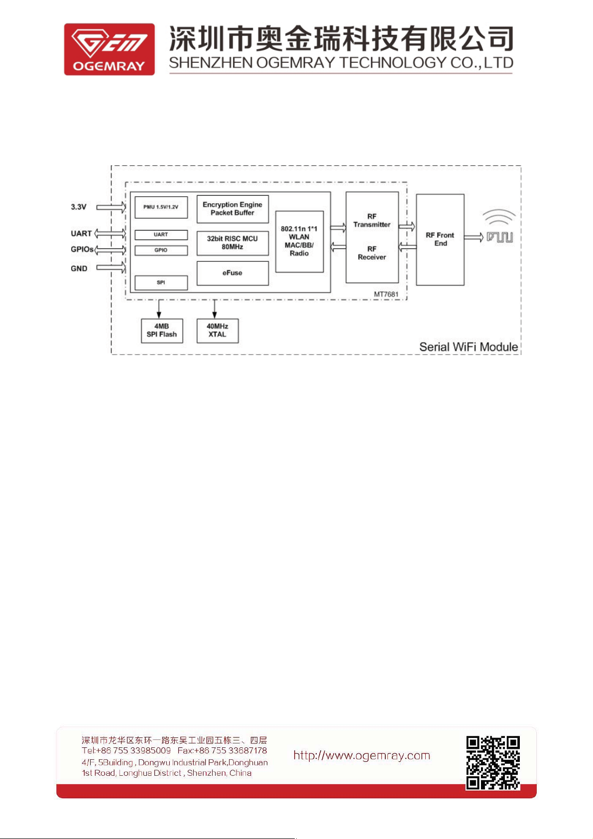
1.3 Block diagram
Fig. 1- 1 Block diagram--The onboard antenna used
2
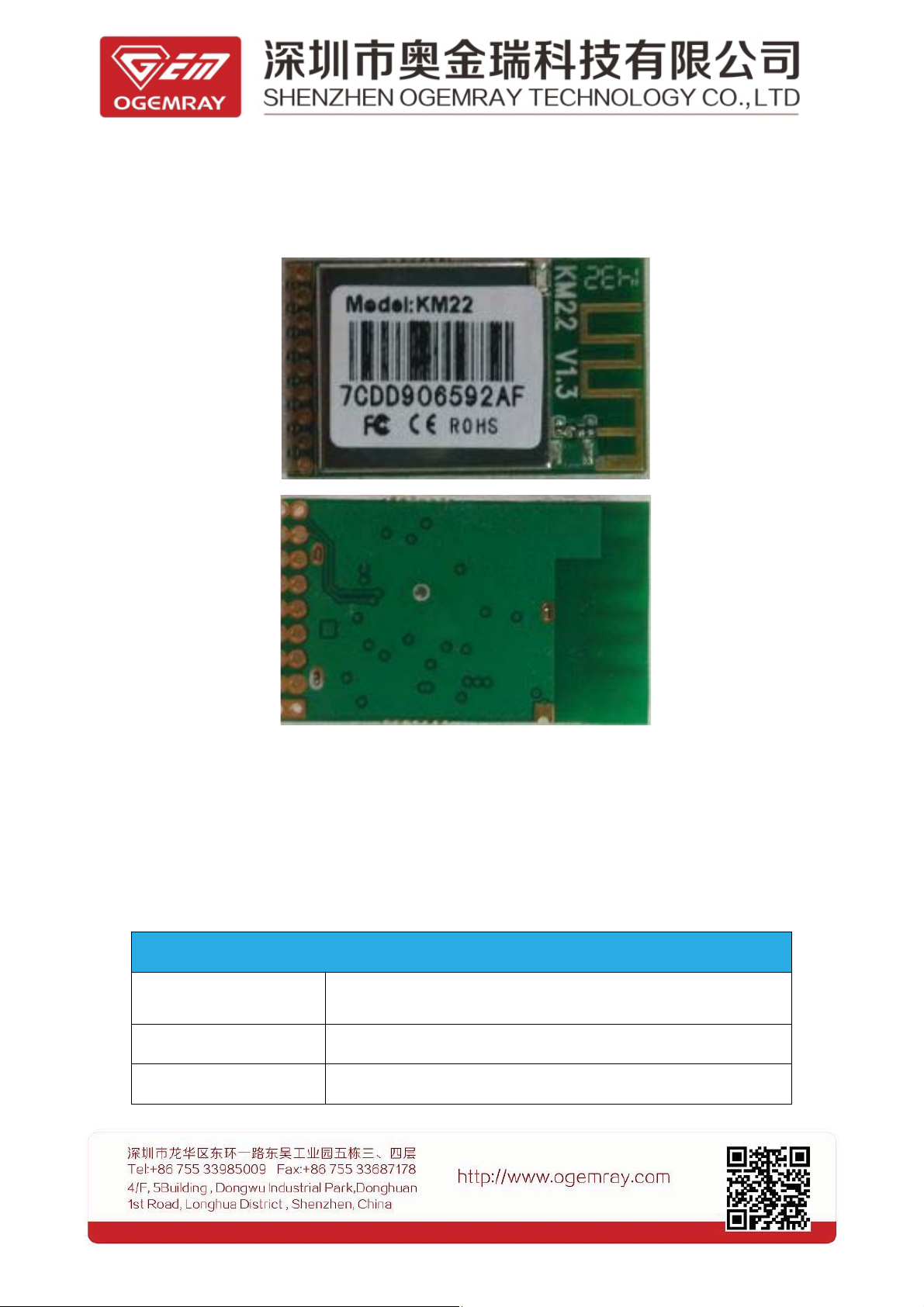
1.4 Outline
1.5 Specification
Table1 1–1 General Specification
Protocol and interface
WiFi Protocol IEEE 802.11b/g/n
Data interface 1 UART, Max data rate:115200bps
I/O ports 4 GPIO
Fig. 1- 2 Outline reference picture
3

LED display Link/Activity display
Memory size
External SPI Flash 4Mbit
WiFi Features
WiFi mode Client / Soft AP mode
Encryption
WPA2-PSK,WEP ( more will be available later)
WiFi RF Characteristics
Frequency ISM band, 2412~2462MHz.
802.11b (CCK) 11Mbps: 19.5+/-1dBm
Tx power
802.11g (OFDM) 54Mbps: 21.5+/-1dBm
(Peak value)
802.11n(HT20@MCS7),20.5+/-1dBm
802.11b: -86+/-1dBm;
Rx sensitivity
802.11g: -72+/-1dBm,
802.11n (HT20), -68+/-1dBm;
Operation Voltage and Current (Typical)
Power supply 3.3+/-0.05 VDC
1.1mA Sleep mode
6mA RX listen mode
15mA RX power saving, DTIM=1
Current
70mA RX Active、MCS7
220mA 802.11g (OFDM) 54Mbps
210mA
245mA 802.11b (CCK) 11Mbps
Operation Condition
Operating temperature -10ºC to +60ºC
Storage temperature -20ºC to +80ºC
802.11n (HT20@MCS7)
4

Operating humidity 20% to 80%
Physical
Size 30*18mm
Weight 2.4g
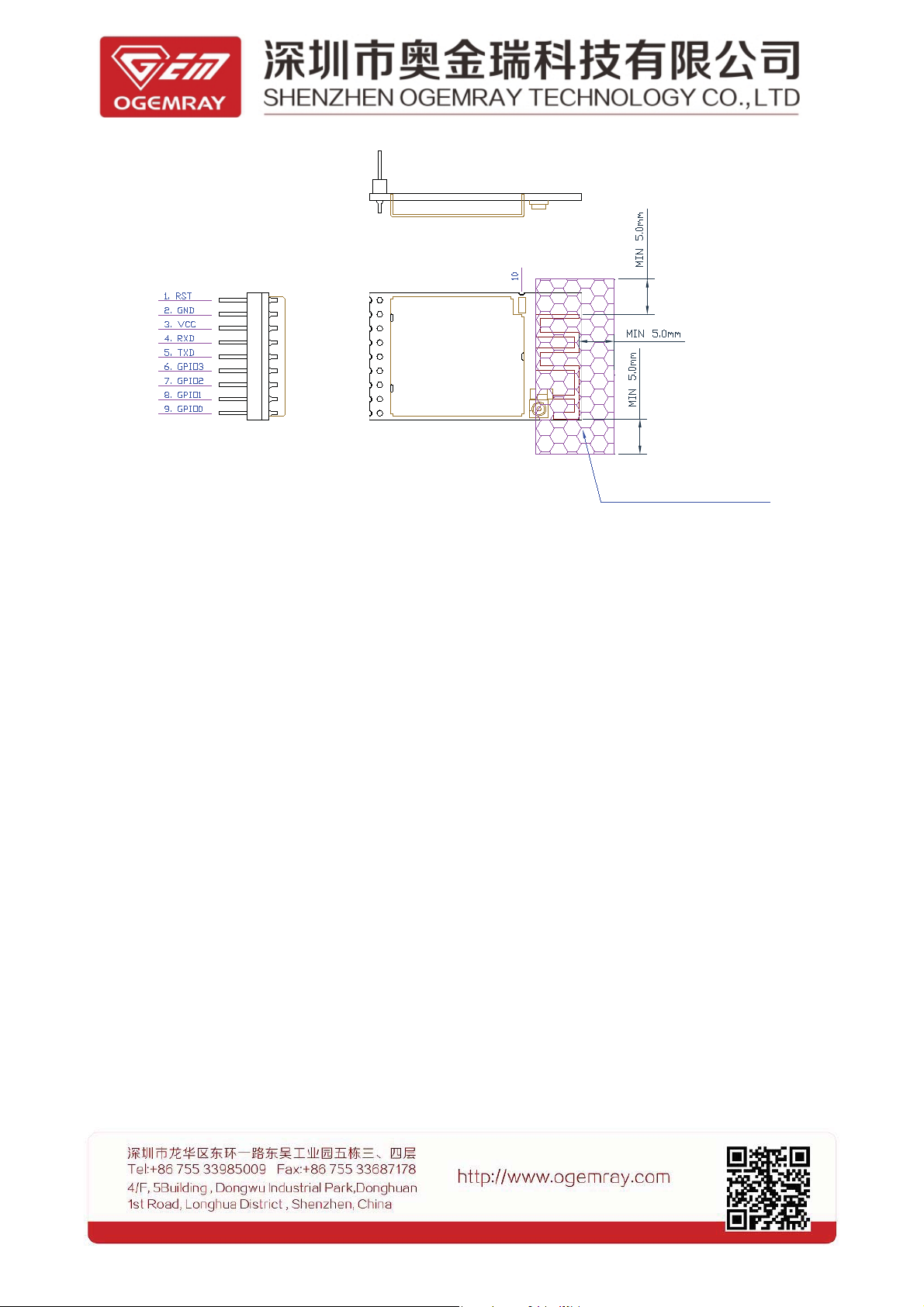
1.6 Pinout configuration
Shield Case
Table1 1–2 Pin configuration
Pin Name Description
1 RST External reset active low
2GND GND
LED
Shield Case
Fig. 1- 3 Pin definition overview
5

3VCC 3.3V
4 RXD UART_RXD(UART Receive data)
5 TXD UART_TXD(UART transmit data)
6 GPIO3 GPIO3
7 GPIO2 GPIO2
8 GPIO1 GPIO1
9 GPIO0 GPIO0
10 NC Not Connection
Notes: 1. GPIO0〜3 can be pulled up to low or high
2. For the time being only UART/GPIO supported
3. Pin 10 must ben’t connected
4、GPIO1 has been reserved for a AT command mode switching, high level is the AT
command mode, low level is pure data model
1.7 Characteristics
Table 1- 3 Absolute Max Rating
Symbol Description Max rating Unit
VCC 3.3V power input -0.3~3.6 V
VESD ESD protection (HBM) 2000 V
Table 1- 4 DC Characteristic
Symbol Description Condition Min Typ Max Unit
3.3VD Power supply 3.3V 2.97 3.3 3.63 V
V
IL
V
IH
Input low voltage
Input low voltage 2.0 3.3 3.63 V
-0.28 N/A 0.6 V
LVTTL
V
T-
V
T+
V
OL
V
OH
R
PU
R
PD
Negative trigger 0.68 N/A 1.36 V
Positive trigger 1.36 N/A 1.7 V
Output low voltage IIOLI=1.6~14mA -0.28 N/A 0.4 V
Output high voltage IIOHI=1.6~14mA 2.4 N/A 3.63 V
Input pull-up
resistance
Input pull-down
resistance
PU=high,PD=low
PU=low,PD=high
6
40 N/A 190 KΩ
40 N/A 190 KΩ

2. Reminds to hardware design
2.1 Application
The module is designed with an UART interface, it support TCP/IP protocol, users
can use the UART port to transfer data via WiFi connection to other internet devices.
Fig. 2-1 To use external MCU
2.2 GPIO Descriptions
The KM22 module designed with 4 GPIO port , the fastest interrupt request time is about 1ms。
Each GPIO port can be individually configured as an input or output via software. To stabilize the
interface communication, you can add a pull-push circuit as below:
Fig. 2- 2 Reference design of GPIO pins
Notes: The supply voltage is 3.3V for this module. The default voltage setting of GPIO is also 3.3V.
Should other voltage system be applied, a voltage converter must be used.
Remarks: the GPIO3 was default assigned for LED display, if this port must be used for other
7

purpose; please specify the requirement when ordering, so that the onboard LED can be removed
during production.
2.2.1 LED Display
When an external LED to be used, a recommended connection shows as below:
Fig. 2- 3 Reference design for external LED connection
* the 470 ohm resistor can be changed to a value depends on the brightness of the LED.
2.3 UART interface
UART interface
Pin Pin name I/O Instruction
4 RXD I UART_RXD(UART Receive data)
5 TXD O UART_TXD (UART transmit data)
Table 2- 1 UART interface
The Super terminal or Tera or SecureCRT tool can be sued to test or debug the UART。
The UART setting is 115200,8-N-1; A reference design connection like:
Fig. 2- 4 UART reference connection diagram
8

2.4 Power supply
Table 2- 2 pin configuration
pin Symbol Description
2 GND Ground
3 3.3VD 3.3Vpower input
Since the module needs clean and low ripple 3.3V DC power supply, please properly design the power
supply to this module, otherwise the RF performance of the module might be deteriorated.
2.5 RF output
A、onboard antenna
Fig. 2-5 Reference pic with onboard antenna
9

2.6 Dimensions
Shield Case
LED
Shield Case
Fig. 2-6 Dimensions
2.7 Clear place to use the module
The following drawing shows a recommended footprint which can be a reference for a
main PCB design.
The clear space requirement for onboard antenna is suit for either pin header or
semi-holes connection application.
10
Shield Case
:
Shield Case
Fig. 2-7 Clear space needed
Note: Pin 10 must ben’t connected
3.Software descriptions
LED
Metallic Clear Area
Right now, to develop customized application, the SDK software pack provided by the chipset
manufacturer MTK is recommended to use. Other kind of software supported is not available yet.
3.1 AT command
This module applies the chipset MT7681, it has its own internal MCU which can be used to fulfill
some sort of software functions. For most of users, to simplify the technology requirement of
software programming, an external cheap or simple MCU might be used. In this kind of application,
the internal MCU of MT7681 will be limited and can’t be approached by normal users.
When an external MCU is selected, several future integrated AT commands may be provided
and useful to expedite the software design rather than spend much time to know the kernel Linux
driver of the MT7681
The command format
AT#Command -Parameters +enter
11

Command Parameters Descriptions
Ver none Display ver
Reboot none Reboot
Default none Load default
Smtconn none Start smart connection mode
Conn_AP -sSSID -pPassword Connect ap
Uart_Wifi
Mac none Display the device MAC
GPIO -p(pin) -w(0/1) -r(0/1) Write/Read GPIO
WMode -w(0/1) Switch to AP/STA mode
Puredata none Enter the pure data mode
-n(0/1) -m(0/1) -i(ip-addr) -l(local
port) -r(remort port)
Open TCP/UDP Server/Client
4.Certificate and Approval
Table 4- 1 Certificates and Approval
Certificates Remarks
FCC part15 Not ready yet
CE Not ready yet
RoHS Not ready yet
5.Disclaimer
THESE MATERIALS AND INFORMATION ARE PROVIDED “AS IS” WITHOUT WARRANTYOF ANY
KIND, EITHER EXPRESS OR IMPLIED , INCLUDING BUT NOT LIMITED TO, THEIMPLIED
WARRANTIES OF MERCHANTABILITY, FITNESS FOR A PARTICULAR PURPOSEOR
12

NON-INFRINGEMENT.
We use reasonable efforts to include accurate and up-to-date information on this document; it does not,
however, make any representations as to its accuracy or completeness of the information, text, graphics,
links or other items contained within these materials. Your use of this Document is at your own risk.
Ogemray, its suppliers, and other parties involved in creating and delivering this Document’s contents
shall not be liable for any special, indirect, incidental, or consequential damages, including without
limitation, lost revenues or lost profits.
FCC Statement
This device complies with Part 15 of the FCC Rules. Operation is subject to the following two conditions:
(1) this device may not cause harmful interference, and (2) this device must accept any interference
received, including interference that may cause undesired operation.
Caution!
Any changes or modifications not expressly approved by the party responsible for compliance could
void the user's authority to operate the equipment.
FCC Radiation Exposure Statement
The modular can be installed or integrated in mobile or fix devices only. This modular cannot be installed
in any portable device, for example, USB dongle like transmitters is forbidden.
This modular complies with FCC RF radiation exposure limits set forth for an uncontrolled environment.
This transmitter must not be co-located or operating in conjunction with any other antenna or transmitter.
This modular must be installed and operated with a minimum distance of 20 cm between the radiator an
duserbody.
If the FCC identification number is not visible when the module is installed inside another device, then th
e outside of the device into which the module is installed must also display a label referring to the enclos
ed module. This exterior label can use wording such as the following: Contains Transmitter Module FCC
ID: YWTWF7681KMX or Contains FCC ID: YWTWF7681KMX
when the module is installed inside another device, the user manual of this device must contain below w
arning statements;
1. This device complies with Part 15 of the FCC Rules. Operation is subject to the following two condition
s:
(1) This device may not cause harmful interference.
(2) This device must accept any interference received, including interference that may cause undesired o
peration.
13

2. Changes or modifications not expressly approved by the party responsible for compliance could void t
he user's authority to operate the equipment.
The devices must be installed and used in strict accordance with the manufacturer's instructions as desc
ribed in the user documentation that comes with the product.
14
 Loading...