


All rights reserved by Shenzhen Ogemray Technology Co., Ltd.
GWF-KM26
Product Specification
(2.4GHz/72.2Mbps 802.11 b/g/n)
ITEM:GWF-KM26
VERSION:V1.0
DATE:2016-11-15
The content can’t be modified without permission in this document
Historical Releases
Version
Modified Content
Writer
Auditing
date
Department
V1.0
the first version
Jasmine
Ning Qing
2016-11-15
Product dept.

Catalogue
1. Product Introduction
1.1 Overview
1.2 Features
1.3 Product Diagram
1.4 Appearance
1.5 Specification
1.6 Interface Definition
1.7 Electrical Features
1.8 Digital Port Features
2. Hardware Design Notice
2.1 Application Diagram
2.2 GPIO
2.3 UART
2.4 Design requirement of practical application
2.4.1 Reset Sequence
2.5 Power Supply Interface
2.6 RF Input and Output Interface
2.7 Dimension
2.8 No wiring area
3. Approval and Certification
4. Disclaimer
...........................................................................................................................................................
............................................................................................................................................................
..................................................................................................................................................................
................................................................................................................................................................
.............................................................................................................................................................
..............................................................................................................................................
...............................................................................................................................................
.......................................................................................................................................................
......................................................................................................................................................
...........................................................................................................................................
.............................................................................................................................................
.........................................................................................................................................
.........................................................................................................................................
.........................................................................................................................................
...................................................................................................................................
...................................................................................................................................
........................................................................................................................
.......................................................................................................................................................
.................................................................................................................................................
....................................................................................................................................
..................................................................................................
1
1
2
3
3
4
6
8
8
9
9
9
10
10
10
11
11
14
15
15
16

Figure Catalogue
Figure 1- 1 GWF-KM26
Figure 1- 2 ESP8266EX Functional block diagram
Figure 1- 3 GWF-KM26 Front View
Figure 1- 4 Dimension
Figure 1- 5 Pin
Figure 2- 1 Application Diagram
Figure 2- 2 GPIO reference design
Figure 2- 3 LED reference design
Figure 2- 4 UART reference design
Figure 2- 5 KM26 external reset sequence
Figure 2- 7 On-board antenna
Figure 2- 8 Antenna pattern
Figure 2- 9 Dimens
Figure 2- 10 No wiring area
.........................................................................................................................................................
............................................................................................................................................
.........................................................................................................................
.............................................................................................................................................
.............................................................................................................................
..........................................................................................................................
..........................................................................................................................
.......................................................................................................................
...........................................................................................................
..............................................................................................................................
.................................................................................................................................
................................................................................................................................................
..................................................................................................................................
Table Catalogue
..................................................................................................
2
3
3
4
6
9
9
10
10
11
12
12
14
15
Table 1- 1 GWF-KM26 Specification
Table 1- 2 GWF-KM26 Pin Definition
Table 1- 3 Pin Mode
Table 1- 4 Pin Instruction
Table 1- 5 Electrical features
Table 1- 6 Data port features
Table 2- 1 UART pin definition
Table 2- 2 Power supply pin definition
Table 3- 1 Approval and Certification
................................................................................................................................................
........................................................................................................................................
.......................................................................................................................
...................................................................................................................................
..................................................................................................................................
..............................................................................................................................
......................................................................................................................
.................................................................................................................
...................................................................................................................
4
6
7
7
8
8
10
11
15

1. Product Introduction
1.1 Overview
GWF-KM26 adopted ESP8266EX platform, the chip work at 2.4G frequency. ESP8266EX is
among the most integrated Wi-Fi chips in the industry. Measuring just 5mm*5mm, ESP8266EX
requires minimal external circuitry and integrates a 32-bit Tensilica MCU, which features extra low
power consumption and 16-bit RISC, the main frequency support 80MHz and 160MHz. With RTOS,
it integrate WiFi MAC/BB/RF/PA/LNA/on-board antenna.
GWF-KM26 support IEEE802.11 b/g/n standard. Using TCP/IP complete protocol stack, user
can use the module to add WiFi network function, it will also establish independent network
controller.
ESP8266EX is a high-efficiency SOC, it offer the unprecedented practicality by low cost, which
offer unlimited possibilities for WiFi technology applied to other control system.
ESP8266EX is a complete and self-contained WiFi solutions, it can not only run independently,
but also work when carried on other host MCU. If ESP8266EX is loaded application as the only
application processor, it will be set up from external flash. Built-in with high speed buffer memory,
it is conductive to enhance system performance and reduce RAM demand.
In other case, ESP8266EX take charge of accessing to WiFi adapter, we can add it to any MCU
design, it is easy and convenient. Just need to thorough SPI/SDIO interface or I2C/UART interface.
Great capacity for management and memory function make it integrate sensors or other
application by GPIO, which occupy the least system resource.
With highly integrated on-chip features and minimal external discrete component count, the
chip offers reliability, compactness and robustness critical in end products.
1.2 Features
Support 2.4GHz, 802.11b/g/n
Integrate Tensilica L106 low consumption 32-bit MCU, the main frequency support
Built-in 10-bit high-precision ADC.
TCP/IP protocol stack.
Integrate TR switch, balun, LNA, power amplifier and matching network.
With PLL, AVR and power management part, 20 dBm output power in 802.11b mode.
A-MPDU, A-MSDU,0.4 s protection interval.
Support WPA/WPA2 Security mode.
Support AT remote upgrade and OTA upgrade.
Support STA/AP/STA+AP work mode
Support Smart-Config function(Android& iOS device)
HSPI,UART, I2C,I2S,IR Remote Control, PWM, GPIO
Deep sleep current is 10 μA , turn-off current is less than 5 μA .
Wake up, connect and transfer data in 2ms.
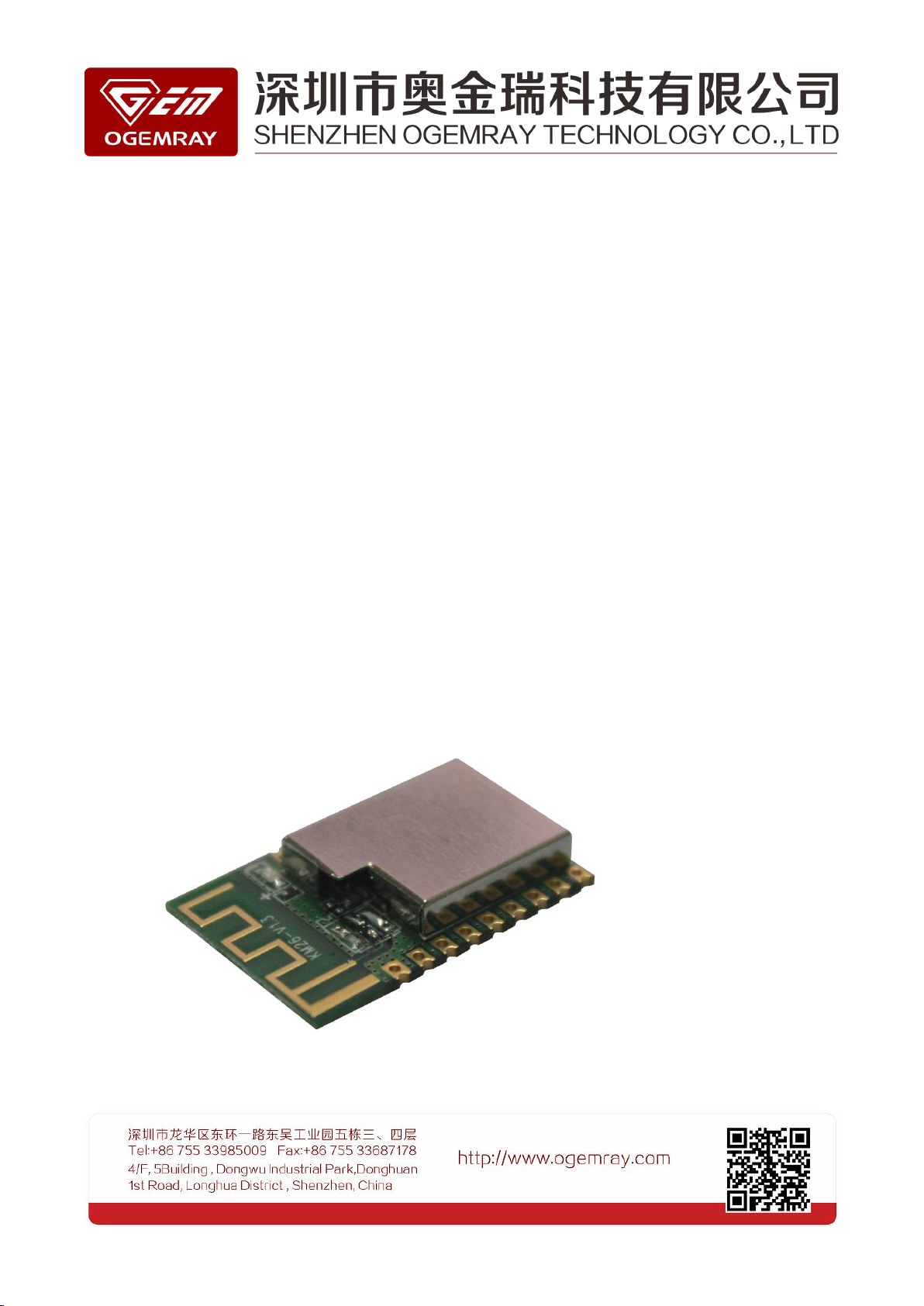
Figure 1- 1 GWF-KM26
80MHz and 160MHz. With RTOS.
1.3 Product Diagram
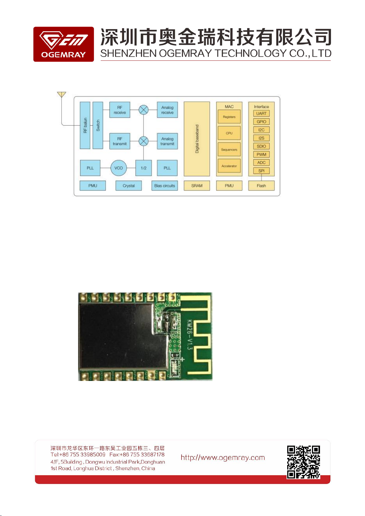
Figure 1- 2 ESP8266EX Functional block diagram
Figure 1- 3 GWF-KM26 Front View
1.4 Appearance
GWF- KM26 dimension is 24.3mm*16mm*3.65mm (As shown in the figure below). The SPI flash
capacity is 8 Mbit packaging SOP-208 mil.

1.5 Specification
Protocol and Interface Standard
WiFi Standard
IEEE 802.11b/g/n
Data Interface
UART/HSPI/I2C/I2S/IR Remote Control
GPIO/PWM
I/O Interface
9 GPIO
LED
When the LED flash slow, the module is not access to WiFi.
When LED is on, the module has been accessed to WiFi.
Memory
SPI Flash
8 Mbit
WiFi Features
Table 1- 1 GWF-KM26 Specification
Figure 1- 4 Dimension

WiFi work mode
STA/AP/STA+AP/Smart Config
RF Security mode
WPA,WPA2
Encryption type
WEP/TKIP/AES
WiFi RF Parameter
Frequency
2.4GHz-2.5GHz (2412MHz-2462MHz)
TX PWR
802.11b (CCK) 11Mbps: 20+/-1.5dBm
802.11g (OFDM) 54Mbps: 15.5+/-1.5dBm
802.11n(HT20@MCS7) 72.2Mbps: 14.5+/-1.5dBm
Running Current
Power Supply
3.0~3.6V(3.3V)
Running Current
80mA (average value)
Working Condition
Work Temperature
-10ºC to +60ºC
Storage Temperature
Normal Temperature
Work Humidity
5% to 95%(no condensing)
Physical Specification
PCBA dimension
24.3mm*16mm*3.65mm
RF Range
Indoor: 45m; Outdoor: 150m(To be depended on the real environment)

1.6 Interface Definition
No.
Pin
Function Instruction
1
GND
GND
2
ADC
A/D result, input voltage range: 0~1V, value range: 0~1024
3ENChip enable interface, active high enable.
4
IO16
GPIO16;
Connecting it to RST pin to wake up deep sleep mode.
5
IO14
GPIO14; HSPI_CLK
6
IO12
GPIO12; HSPI_MISO
7
IO13
GPIO13; HSPI_MOSI; UART0_CTS
Table 1- 2 GWF-KM26 Pin Definition
Figure 1- 5 Pin

8
IO15
GPIO15; MTDO; HSPICS; UART0_RTS
9
IO2
GPIO2; UART1_TXD
10
RXD
UART0_RXD; GPIO3
11
TXD
UART0_TXD; GPIO1
12
IO5
GPIO5
13
IO0
GPIO0
14
IO4
GPIO4
15
3V3
3.3V Power Supply
16
GND
GND
17
RST
Reset
Table 1- 3 Pin Mode
Mode
GPIO15
GPIO0
GPIO2
UART download mode
Low
Low
High
Flash Boot mode
Low
High
High
Interface
Pin
Function Instruction
PWM
IO12(R),
To control color, buzzer, relay, motor and so on.
IR
IO14(IR_T), IO5(IR_R)
IR Remote Control4 interface is implemented by software, the interface
use NEC coding and modem, 38KHz carrier modulation
ADC
TOUT
To detect VDD3P3 (Pin3,Pin4) power voltage an TOUT(Pin6) and input
voltage(can’t be use at the same time);
Sensor application.
I2C
IO14(SCL), IO2(SDA)
To connect to external sensor and display.
UART
UART0: TXD(U0TXD),
RXD(U0RXD),
IO13(CTS)
To connect to external device UART interface.
Download U0TXD+U0RXD or GPIO2+U0RXD.
Communication (UART0): U0TXD, U0RXD, MTDO(U0RTS), MTCK(U0CTS)
Debug: UART1_TXD (GPIO2),it can be served as debug information print.
Table 1- 4 Pin Instruction

UART1: IO2(TXD)
UART0 output printing information by ESP8266EX in default. Developers
can user the internal exchange function of UART to interchange U0TXD,
U0RXD and U0RTS,U0CTS at the time of initialization, To connect MTDO
and MTCK to corresponding UART of external MCU.
I2S
I2S Input:
IO12 (I2SI_DATA) ;
IO13 (I2SI_BCK );
IO14 (I2SI_WS);
It is utilized for audio collection, process and transmission.
I2S Output:
IO15 (I2SO_BCK );
IO3 (I2SO_DATA);
IO2 (I2SO_WS).
1.7 Electrical Features
Rated Value
Condition
Range
Unit
VCC
IPC/JEDEC J-STD-020
+3.0 to +3.6
V
VESD
ESD Protection (HBM)
2000
V
Port
Typical Value
Minimum
Typical Value
Maximum
Unit
Input Logical Level Low
VIL
-0.3
0.25VDD
V
Input Logical Level High
VIH
0.75VDD
VDD+0.3
V
Output Logical Level Low
VOL
N
0.1VDD
V
Output Logical Level High
VOH
0.8VDD
N
V
Table 1- 5 Electrical features
1.8 Digital Port Features
Table 1- 6 Data port features

2. Hardware Design Notice
2.1 Application Diagram
Figure 2- 1 Application Diagram
Figure 2- 2 GPIO reference design
The module support general UART and network standard. Built-in TCP/IP protocol stack, users
can use the module to add network function. It also can establish independent internet controller
to realize data transmission between UART and WiFi internet. Using GWF-KM26 WiFi module,
traditional UART device could be connected to the WiFi network without changing any
configuration, to provide complete and quick solutions for UART device. There are two methods to
control external devices, the first is that external MCU control WiFi module UART. Secondly, KM26
controls external devices by its self-contained UART.
The following is application diagram:
2.2 GPIO
There are 9 GPIO in the module, the minimum interrupt response time is 1ms, these GPIO could be
configured by software directly like UART, LED, IR control.

To control LED brightness by adjusting resistance value of R8.
UART interface
Pin
Pin name
I/O
Instruction
10
RXDIUART_RXD(UART Receive Data)
11
TXDOUART_TXD (UART Transmit Data)
Figure 2- 3 LED reference design
Figure 2- 4 UART reference design
Note: If the LED is in semi-bright for a long time, please try to reset.
2.3 UART
Table 2- 1 UART pin definition
GWF-KM26 default configuration
10 pin for UART RXD
11 pin for UART TXD
Hyper terminal, Tera or Secure CRT can be regarded as communication tools for UART interface debug.
The UART setting is 115200; 8-N-1.
The following figure is a reference design selection.
2.4 Design requirement of practical application
2.4.1 Reset Sequence
KM26 need to reset external reset signal (Active Low ),external reset sequence as shown in the figure below:

T3: 30ms ~50ms
2.5
Power Supply Interface
Pin No.
Pin
I/O
Instruction
16
GND
Power
Ground
15
VCC
Power
3.3V Input
Figure 2- 5 KM26 external reset sequence
Power Supply Interface
Table 2- 2 Power supply pin definition
Because module need low ripple DC power supply, please design the power module accurately, otherwise, it may
lead to RF performance degradation.
2.6 RF Input and Output Interface
A. Using on-board antenna, we need to place 1nH inductance, remain IPEX empty.

Figure 2- 6 On-board antenna
Figure 2- 7 Antenna pattern
Peak gain: -1dBi; average gain: -3dBi
B. External antenna is connected to IPEX by RF cable, we should not add inductance to the board.

Above figure is suggested antenna(Airgain P / N:N2420)and its antenna pattern.

2.7 Dimension
Figure 2- 8 Dimens

2.8 No wiring area
3. Approval and Certification
Certification
Approval
FCC part15
Ongoing
CE
Ongoing
RoHS
Pass
Figure 2- 9 No wiring area
Table 3- 1 Approval and Certification

4. Disclaimer
These material and information are provided “as is” without warranty of any kind, either express of
implied, including but not limited to, the implied warranties of merchantability, fitness for a particular
purpose or non-infringement.
We use reasonable efforts to include accurate and up-to-date information on this document, it does
not, however, make any representations as to its accuracy or completeness of the information, text, graphics,
links or other items contained within these materials. Your use of this Document is at your own risk.
Ogemray, its suppliers, and other parties involved in creating and delivering this Document’s contents shall
not be liable for any special, indirect, incidental, or consequential damages, including without limitation, lost
revenues or lost profits.

FCC Caution: Any changes or modifications not expressly
approved by the party responsible for compliance could void the user's
authority to operate this equipment.
This device complies with Part 15 of the FCC Rules.
Operation is subject to the following two conditions: (1) This device may not
cause harmful interference, and (2) this device must accept any interference
received, including interference that may cause undesired operation.
This device and its antenna(s) must not be co-located or operating in conjunction
with any other antenna or transmitter.
15.105 Information to the user.
(b) For a Class B digital device or peripheral, the instructions furnished the
user shall include the following or similar statement, placed in a prominent
location in the text of the manual:
Note: This equipment has been tested and found to comply
with the limits for a Class B digital device, pursuant to part 15 of the FCC Rules.
These limits are designed to provide reasonable protection against harmful
interference in a residential installation. This equipment generates, uses and
can radiate radio frequency energy and, if not installed and used in
accordance with the instructions, may cause harmful interference to radio
communications. However, there is no guarantee that interference will not
occur in a particular installation. If this equipment does cause harmful
interference to radio or television reception, which can be determined by
turning the equipment off and on, the user is encouraged to try to correct the
interference by one or more of the following measures:
—Reorient or relocate the receiving antenna.
—Increase the separation between the equipment and receiver.
—Connect the equipment into an outlet on a circuit different from that to which
the receiver is connected.
—Consult the dealer or an experienced radio/TV technician for help.
This equipment complies with FCC radiation exposure limits set forth for an uncontrolled environment. This
equipment should be installed and operated with minimum distance 20cm between the radiator and your bo
dy.
Radiation Exposure Statement:
This equipment complies with FCC radiation exposure limits set forth for an uncontrolled environment.
This transmitter must not be co-located or operating in conjunction with any other antenna or transmitter.
The module should not be installed and operated simultaneously with other radios except additional RF
exposure was evaluated for simultaneously transmission.
The availability of some specific channels and/or operational frequency bands are country dependent and
are firmware programmed at the factory to match the intended destination.
The firmware setting is not accessible by the end user.
The final end product must be labelled in a visible area with the following:
“Contains Transmitter Module YWT-KM26”
 Loading...