

All rights reserved
MODEL: GWF-5M02
VERSION: V1.0
DATE: 2017-06-13
GWF-5M02
PRODUCT SPECIFICATION
All information contained in this specification may not be changed without permission
1 / 13
Historical Releases
Version
Modified Content
Writer
Auditing
date
Department
V1.0
the first version
Jasmine
Ning Qing
2017-06-13
Product dept.
2 / 13

Catalogue
Catalogue
1.Product Basic Information 4
1.1 Product Introduction 4
1.2 Product Features 5
2 Product Basic Function 5
2.1 Brief Specification 5
2.2 Hardware Information 5
2.3 Software Information 9
2.4 Mechanical Information 9
2.4.1 Product Appearance 9
2.4.2 Product Dimension 9
2.4.3 RF output Connection Information 10
3. Approval and Certification 12
4.Environment Requirements 12
4.1 Suitable Temperature 12
4.2 Suitable Humidity 12
5. Available WLAN Channels in Major Countries 13
6. Disclaimer 13
3 / 13
Product
1.1.Product
1.1
Product
1.1
Product
The 5M02 is a low cost and multi-use WLAN module, it adopts the latest 802.11ac technology and fully
complies with 802.11a/b/g/n/ac standards.
The 5M02 module designed is to focusing on wireless connection, equipped with 4/6 pin connectors, it
supports USB1.0/USB2.0 interface. The module uses high-integration MAC/BBP chip and RF single chip
RTL8811AU. These features deliver reliable performance, extensive application and operational excellence.
Built in on-board antenna, developers also can connect 5G or 2.4G antenna. The working frequency
range is in 5.8GHz/2.4GHz. Under ideal circumstance, the transmission rate reaches to 433Mbps, users can
choose one of frequency to avoid wireless interference and network congestion. It has more stable wireless
signal and more smooth running speed.
The module is a broadband network mode, the bandwidth reaches to 80MHz, it is effective for users to
avoid network delay. The module can be applied for IP camera, IP STB, GPS, TV, internet broadcast device,
etc. It makes network running more fluently for voice, video, online music, internet games to deliver a better
Basic
Basic
Introduction
Introduction
Information
Information
experience. 5M02 supports multi advanced encryption mode, which offers safer network environment.
The 5M02 modules have extensive operational compatibility, it supports current mainstream operation
system like Windows Vista, XP/7/8/10, Linux, Mac OS; All these remove trouble of compatibility.
GWF-5M02
4 / 13
1.2
Built in on-board antenna, or connect to external antenna via IPEX.
WPS supports.
802.11b: 1, 2, 5.5, 11Mbps
802.11g: 6, 9, 12, 18, 24, 36, 48, 54Mbps
802.11n: (20MHz) MCS0-7, PHY rate reaches to 72Mbps; (40MHz) MCS0-7, PHY rate reaches to
802.11ac: PHY rate reaches to 433Mbps(80MHz)
Support multiple encryption mode: WFA, WPA, WPA2, Personal, WPS2.0, WAPI.
Equipped with 4/6 pin connector, support USB2.0/1.1 interface
Built-in power consumption management function
Excellent interference resistance ability
System support: Windows Vista, XP/7/8/10, Linux, Mac OS
Electronic Specification
Main Chipset
RTL8811AU
Interface
4/6 pin connector, support USB2.0/1.1 interface
Standard
IEEE802.11b/g & 802.11n & 802.11ac(1T1R mode
)
Operation Frequency
Antenna
on-board antenna, or connect to external antenna via I-PEX
location hole
3 location holes
Product
1.2
Product
72Mbps
NOTICE: WLAN communication channel is the communication channel used for IEEE 802.11 (Wi-Fi)
wireless network permitted by national laws. It is divided to 2 different independent bands by 802.11 working
team. Though each band can be partitioned to several communication channels, every country has its own
Features
Features
authority to decide how to use them. You can refer to CHAPTER 5 for detailed information.
Product
22Product
2.1
Brief
2.1
Brief
Basic
Basic
Specification
Specification
Function
Function
2412MHz - 2462MHz, 5180MHz - 5240Hz, 5745MHz - 5825MHz,
5 / 13

Encryption mode
WFA, WPA, WPA2, Personal, WPS2.0, WAPI.
Typical Transmit Power
(feed point to antenna)
802.11b: 17±1 dBm@11Mbps
Receive Sensitivity
802.11b: -80+/-1dBm
802.11g: -73+/-1dBm
802.11n: -70+/-1dBm(HT20); -64+/-1dBm(HT40)
802.11ac: -80+/-1dBm(MCS0); -56+/-1dBm(MCS9) ,(AC80)
Operating Voltage
5V DC+/-5%
Power consumption
TX and RX status: 220mA(max)
TX status: 220mA(max)
RX status:180mA(max)
Physical Specification
module dimension
45.0* 18.1*2.9 mm
location hole size
diameter: 1.0mm
Weight
3.3 g
802.11g: 15±1 dBm@54Mbps
802.11n: 15±1 dBm@150Mbps
802.11ac: 11±1 dBm@433Mbps(AC80)
6 / 13

2.2
J1 or J2
CONNECTOR
FEM
RTL8811A U
5G/RX
5G/TX
DEX
5G/TX/RX
DUPLEXOR
2.4G/TX/RX
COAXIAL
CONNECTOR
ANTENNA
EXTERNAL
AERIAL
BUILT-IN
ANTENNA
Pin NO.
4-pin 2.0mm pitch
Description
Remark
J-1TXTX enable
Not available temporarily
J-2
DVDD-5V0
USB power
DC 5V+/-0.5V
J-3
UDM
Data-
J-4
UDP
Data+
J-5
GND
GND
J-6
WPS
WPS button outgoing line
3.3V, high level active
Hardware
2.2
Hardware
Information
Information
1. Block diagram
2. 4/6 pin connector interface schematic diagram
3. 4/6 pin connector interface definition and function description as below:
7 / 13

When you consider pull-up resistor (pull-down resistor), you need to think about resistor value.
SW1
2 1
TX
SW2
2 1
WPSVDD33
J2-1
DVDD-5V0
USB power
DC 5V+/-0.5V
J2-2
UDM
Data-
J2-3
UDP
Data+
J2-4
GND
GND
J1-1(TX) connects to GND by pressing SW1 button, it is at 3.3V low level active, now it doesn’t support the
function temporarily.
J1-6(WPS) connect to 3.3V by pressing WPS button(SW2), it is high level active, the schematic diagram as
below.
The following figure us recommended schematic diagram.
8 / 13

2.3
OS
Available
OS Version
Windows
YES
XP
YES
Win7
YES
Win8
YES
Vista
YES
Win10
Linux
YES
Linux2.6 or above
Android
YES
Android2.6 or above
Mac
YES
10.3-10.10
Software
2.3
Software
The table below is for users to check the available Operation System and its version:
2.4
Mechanical
2.4
Mechanical
Information
Information
Information
Information
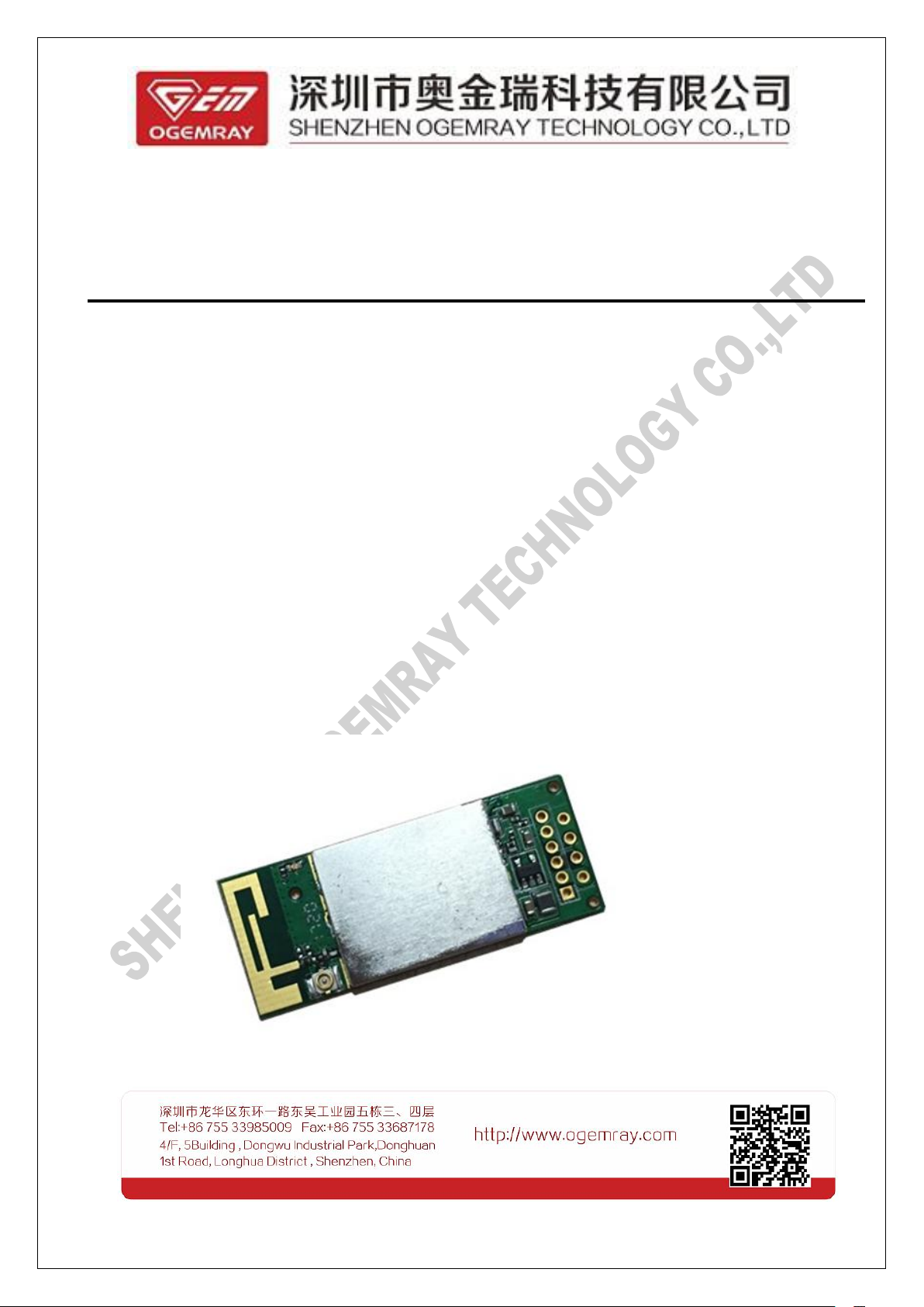
2.4.1 Product Appearance
The view of top and bottom layer of GWF-5M02 can be displayed in the following pictures
2.4.2 Product Dimension
The dimension of GWF-5M02 can be referred by following picture:
9 / 13

Three location holes position map as below (dimension unit: mm):
2.4.3 RF Signal Input and Output
A. Using external antenna to process signal input and output.
If the I-PEX RF connection is selected, a 50 ohm external antenna connects to the module RF output via
10 / 13

an I-PEX MHF receptacle (RF connector).
I-PEX interface can be welded to the suitable position in PCBA
When we use external antenna via I-PEX interface, on-board antenna will interrupt signal
The profile of I-PEX connector is contained in the following picture.
Note:
connection.
B. Using on-board antenna to process signal input and output.
On-board antenna location is as below, users can process signal input and output directly via on-board
antenna, if users think that signal quality can’t satisfy requirement, they can use external antenna.
The peak gain is -1dBi; the average gain is -3dBi.
11 / 13

Approval
Certification
Approval
FCC
Pre-scan undergoing
CE
Pre-scan undergoing
ROHS
Pre-scan undergoing
3.3.Approval
and
and
Certification
Certification
Environment
4.4.Environment
Requirements
Requirements
4.1 Suitable Temperature
Working Temperature: -10℃~+50℃
Storage Temperature: -20℃ ~+85℃
4.2 Suitable Humidity
Working Humidity: 20%~85%
Storage Humidity: 20%~95%
Notice: To keep the normal service life and ensure the excellent working performance of our device,
please use it and store it abide by environment requirements strictly.
12 / 13

Disclaimer
6.6.Disclaimer
This SPECIFICATION document is the guidance of the installation and tentative usage of our products.
Before operating the product, please read this data sheet carefully.
All rights reserved. Any reproduction, translation or simplification of this data sheet in whole or in part is
strictly prohibited without written permission from our company.
We do not provide any guarantee about this data sheet, software or other relevant information. We
solemnly state that there is no implied business warranty or commercial contract assurance in the sheet,
software or other related information. The data sheet is only for operation guidance and reference; it cannot
be used as basis or supplement of any other contract or duty.
13 / 13

FCC Caution: Any changes or modifications not expressly
approved by the party responsible for compliance could void the user's
authority to operate this equipment.
This device complies with Part 15 of the FCC Rules.
Operation is subject to the following two conditions: (1) This device may not
cause harmful interference, and (2) this device must accept any interference
received, including interference that may cause undesired operation.
This device and its antenna(s) must not be co-located or operating in conjunction
with any other antenna or transmitter.
15.105 Information to the user.
(b) For a Class B digital device or peripheral, the instructions furnished the
user shall include the following or similar statement, placed in a prominent
location in the text of the manual:
Note: This equipment has been tested and found to comply
with the limits for a Class B digital device, pursuant to part 15 of the FCC Rules.
These limits are designed to provide reasonable protection against harmful
interference in a residential installation. This equipment generates, uses and
can radiate radio frequency energy and, if not installed and used in
accordance with the instructions, may cause harmful interference to radio
communications. However, there is no guarantee that interference will not
occur in a particular installation. If this equipment does cause harmful
interference to radio or television reception, which can be determined by
turning the equipment off and on, the user is encouraged to try to correct the
interference by one or more of the following measures:
—Reorient or relocate the receiving antenna.
—Increase the separation between the equipment and receiver.
—Connect the equipment into an outlet on a circuit different from that to which
the receiver is connected.
—Consult the dealer or an experienced radio/TV technician for help.
This equipment complies with FCC radiation exposure limits set forth for an uncontrolled environment. This
equipment should be installed and operated with minimum distance 20cm between the radiator and your bo
dy.
Radiation Exposure Statement:
This equipment complies with FCC radiation exposure limits set forth for an uncontrolled environment.
This transmitter must not be co-located or operating in conjunction with any other antenna or transmitter.
The module should not be installed and operated simultaneously with other radios except additional RF
exposure was evaluated for simultaneously transmission.
The availability of some specific channels and/or operational frequency bands are country dependent and
are firmware programmed at the factory to match the intended destination.
The firmware setting is not accessible by the end user.
The final end product must be labelled in a visible area with the following:
“Contains Transmitter Module YWT-5M02”
 Loading...