

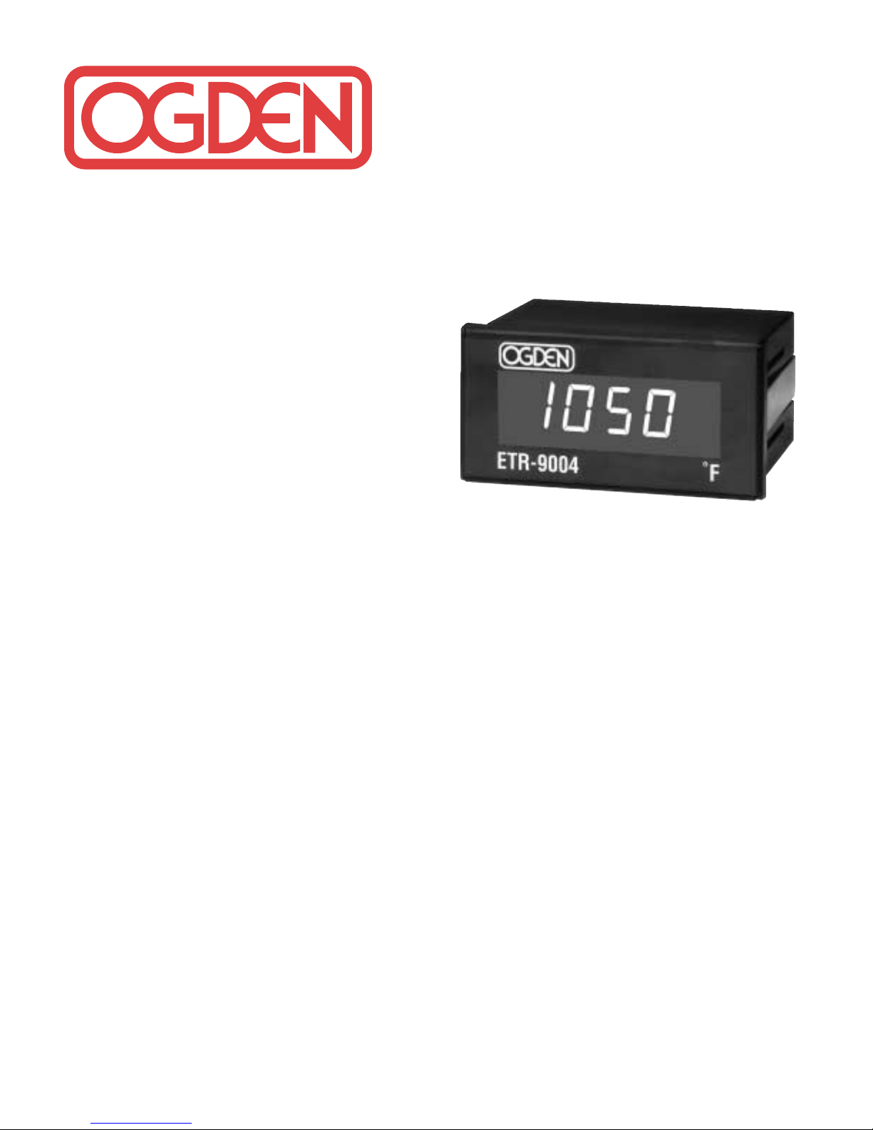
Ogden ETR-9004 Instruction Manual
INSTRUCTION
MANUAL
MANUAL #27
1/8 DIN Solid State Temperature
Indicator Model ETR-9004
All temperature indicators in this series are made to fit
into panel cut-outs which measure 113⁄16” x 35⁄8” (46mm x
92mm). Aminimum of 3
1
⁄2” (89mm) in depth is required
for electrical clearances of rear terminal connections.
The following specifications are common to all models:
INPUT
Thermocouple (T/C) Type K, J. Specified on
Control Label.
RTD PT 100 ohm, 2 or 3-wire
(
= .00385) DIN
(
= .00392) JIS
Cold Junction
Compensation Automatic
Input Break Built-in, upscale on open
sensor.
Input Impedance 1M ohm.
Common Mode
Rejection (CMR) CMRR 120dB, Min.
Normal Mode
Rejection (NMR) NMRR 60dB, Min. (60Hz)
POWER
Rating 120/240VAC field
selectable, 50/60Hz.
12-24VDC models
available on special order.
Accuracy 0.2% of SPAN.
Consumption Less than 3VA.
ENVIRONMENTAL & PHYSICAL
Operating Temperature 10° to 125°F (-12 to 52°C).
Humidity 5 to 90% RH (non-
condensing).
Insulation 20M ohm Min., (5000VDC).
Breakdown 2000VAC, 50/60Hz,
1 minute.
Vibration 10 - 55Hz, Amplitude
1.0mm.
Shock 660 ft./S
2
(20g.)
Weight 11 oz. (312 grams)
DIMENSIONS H – 17⁄8” (48mm)
W – 33⁄4” (96mm)
D – 31⁄4” (83mm)
Depth behind panel – 3”
(76mm)
DIN Case Plastic, with screw
terminals on rear,
adjustable brackets for
panel mounting.
MOUNTING
When mounting the instrument, it is important the
instrument remains within the ambient temperature
range of 10 to 125°F. Mounting it in any position is
permissible. After inserting the instrument into the
panel, secure it with the mounting bracket provided with
each unit.
• Both solderless terminals or “stripped” leads
can be used for power leads. Only “stripped” leads
should be used for thermocouple connections to
prevent compensation and resistance errors.
• Take care not to over-tighten the terminal screws.
• Unused control terminals should not be used as
jumper points as they may be internally connected,
causing damage to the unit. This indicator is not
to be used in hazardous locations as defined in
Article 500 of the National Electric Code.
Telephone: (847) 593-8050 • FAX: (847) 593-8062
© Ogden Manufacturing Co. 1996 PRINTED IN U.S.A. 2/96
MARCA REGISTRADA
OGDEN and ETR are Registered Trademarks of Ogden Manufacturing Co.
Specifications subject to change without notice
TROUBLE SHOOTING
Experience has proven that many control problems are
not caused by a defective instrument. See list below
for some of the common causes of failures:
Line wires are improperly connected.
No voltage between line terminals.
Incorrect voltage between line terminals.
Connection to terminals are open, missing or loose.
Thermocouple or RTD is open at tip.
Thermocouple or RTD lead is broken.
Shorted thermocouple or RTD leads.
Short across terminals.
Burned out line fuses.
Defective line switches.
Defective circuit breakers.
If these points have been checked and the indicator still
does not function, it is suggested that the instrument be
returned to the factory for inspection.
Do not attempt to make repairs. It usually creates
costly damage. Also, it is advisable to use adequate
packing materials to prevent damage in shipment.
Return To:
OGDEN MANUFACTURING CO.
ATTN: Repair Department
719 W. Algonquin Road
Arlington Heights, IL 60005
Temperature Ranges of Ogden Indicators:
ETR-9004-01 0-1200°F Type “J” Thermocouple
ETR-9004-02 0-600°C Type “J” Thermocouple
ETR-9004-03 0-2500°F Type “K” Thermocouple
ETR-9004-04 0-1200°C Type “K” Thermocouple
ETR-9004-05 0-700°F PT-100 RTD DIN
ETR-9004-06 0-450°C PT-100 RTD DIN
CALIBRATION INSTRUCTIONS
W
ARNING–HIGH VOLTAGE PRESENT!
The indicator should be allowed to warm-up for 1/2 hour
before accurately checking calibration.
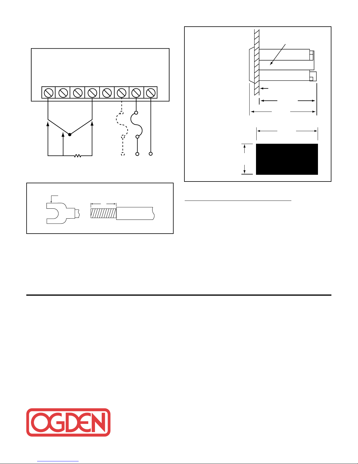
Remove the front faceplate by twisting a flat screwdriver in the slot under the front-center area of the faceplate.
Calibration is accomplished by using the two potentiometers located on the right-hand side of the bottom
PC board. The potentiometer to the right is the zero
adjustment. The potentiometer to the left is the span
adjustment. The two potentiometers have a slight effect
on each other, so calibrate low-scale and high-scale at
least three times.
Mounting
Dimensions
WIRING
All wiring should conform to local and national codes.
Rear Terminal Connections
Panel
Cutout
Mounting Bracket
12
45678
3
+ –
RED
FUSE
3A
T/C
B
B
RTD
SPADE TONGUE
CONNECTOR FOR
NO. 6 STUD
A
3/8"
Lead Termination
240V 0V120V
POWER INPUT
Panel
3"
(76mm)
3-1/4"
(83mm)
3-5/8"
(92mm)
1-13/16"
(46mm)
 Loading...