

Ogden ETR-8300 Instruction Manual
Model ETR-8300
Microprocessor Based
PK488-OMC57
SMARTER LOGIC
®
Temperature Control
S
S
L
L
L
M
M
O
O
O
A
A
R
R
G
G
G
T
T
I
E
I
I
E
C
C
C
R
R
®
INSTRUCTION MANUAL

Warning SymbolWarning Symbol
This Symbol calls attention to an operating procedure, practice, or the like, which, if not correctly performed or
This Symbol calls attention to an operating procedure, practice, or the like, which, if not correctly performed or
adhered to, could result in personal injury or damage to or destruction of part or all of the product and system.
adhered
Do
Do not proceed beyond a warning symbol until the indicated conditions are fully understood and met.
to, could result in personal injury or damage to or destruction of part or all of the product and system.
not proceed beyond a warning symbol until the indicated conditions are fully understood and met.
Use the ManualUse the Manual
Read Chapter 1, 2
Installers
Installers
Basic Function User
Basic
Function User
Enhanced Function User
Enhanced
System Designer
System
Expert User
Expert
Function User
Designer
User
Read Chapter 1, 2
Read Chapter 1, 3, 5
Read
Chapter 1, 3, 5
Read Chapter 1, 3, 4, 5
Read
Chapter 1, 3, 4, 5
Read All Chapters
Read
All Chapters
Read Page 11
Read
Page 11
2

CONTENTS
Page NoPage No Page NoPage No
Chapter 1 OverviewChapter 1 Overview
1-1 Features
1-1 Features
1-2 Ordering Code
1-2
Ordering Code
1-3 Programming Port and DIP Switch
1-3
Programming Port and DIP Switch
1-4 Keys and Displays
1-4
Keys and Displays
1-5 Menu Overview
1-5
Menu Overview
1-6 System Modes
1-6
System Modes
1-7 Parameter Description
1-7
Parameter Description
Chapter 2 InstallationChapter 2 Installation
2-1 Unpacking
2-1 Unpacking
2-2 Mounting
2-2
Mounting
2-3 Wiring Precautions
2-3
Wiring Precautions
2-4 Power Wiring
2-4
Power Wiring
2-5 Sensor Installation Guidelines
2-5
Sensor Installation Guidelines
2-6 Thermocouple Input Wiring
2-6
Thermocouple Input Wiring
2-7 RTD Input Wiring
2-7
RTD Input Wiring
2-8 Linear DC Input Wiring
2-8
Linear DC Input Wiring
2-9 CT / Heater Current Input Wiring
2-9
CT / Heater Current Input Wiring
2-10 Event Input wiring
2-10
Event Input wiring
2-11 Output 1 Wiring
2-11
Output 1 Wiring
2-12 Output 2 Wiring
2-12
Output 2 Wiring
2-13 Alarm 1 Wiring
2-13
Alarm 1 Wiring
2-14 Alarm 2 Wiring
2-14
Alarm 2 Wiring
2-15 RS-485
2-15
RS-485
2-16 RS-232
2-16
RS-232
2-17 Analog Retransmission
2-17
Analog Retransmission
2-18 Programming Port
2-18
Programming Port
Chapter 3 Programming the Basic FunctionChapter 3 Programming the Basic Function
3-1 Input 1
3-1 Input 1
3-2 OUT1 & OUT2 Types
3-2
OUT1 & OUT2 Types
3-3 Rearrange User Menu
3-3
Rearrange User Menu
3-4 Heat Only Control
3-4
Heat Only Control
3-5 Cool Only Control
3-5
Cool Only Control
3-6 Heat - Cool Control
3-6
Heat - Cool Control
3-7 Dwell Timer
3-7
Dwell Timer
3-8 Process Alarms
3-8
Process Alarms
3-9 Deviation Alarms
3-9
Deviation Alarms
3-10 Deviation Band Alarms
3-10
Deviation Band Alarms
3-11 Heater Break Alarm
3-11
Heater Break Alarm
3-12 Loop Break Alarm
3-12
Loop Break Alarm
3-13 Sensor Break Alarm
3-13
Sensor Break Alarm
3-14 SP1 Range
3-14
SP1 Range
3-15 PV1 Shift
3-15
PV1 Shift
3-16 Failure Transfer
3-16
Failure Transfer
3-17 Bumpless Transfer
3-17
Bumpless Transfer
3-18 Self-tuning
3-18
Self-tuning
3-19 Auto-tuning
3-19
Auto-tuning
3-20 Manual Tuning
3-20
Manual Tuning
11
11
12
12
13
13
21
21
21
21
22
22
23
23
24
24
25
25
26
26
26
26
28
28
29
29
30
30
32
32
34
34
35
35
36
36
37
37
38
38
39
39
40
40
41
41
42
42
43
43
44
44
45
45
47
47
48
48
50
50
51
51
52
52
53
53
54
54
54
54
55
55
56
56
57
57
58
58
59
59
61
61
4
4
3-21 Signal Conditioner DC Power Supply
3-21 Signal Conditioner DC Power Supply
7
7
3-22 Manual Control
3-22
Manual Control
8
8
3-23 Display Mode
3-23
Display Mode
9
9
3-24 Heater Current Monitoring
3-24
Heater Current Monitoring
3-25 Reload Default Values
3-25
Reload Default Values
Chapter 4 Programming the Full FunctionChapter 4 Programming the Full Function
4-1 Event Input
4-1 Event Input
4-2 Second Set Point
4-2
Second Set Point
4-3 Second PID Set
4-3
Second PID Set
4-4 Ramp & Dwell
4-4
Ramp & Dwell
4-5 Remote Set Point
4-5
Remote Set Point
4-6 Differential Control
4-6
Differential Control
4-7 Output Power Limits
4-7
Output Power Limits
4-8 Data Communication
4-8
Data Communication
4-9 Analog Retransmission
4-9
Analog Retransmission
4-10 Digital Filter
4-10
Digital Filter
4-11 Sleep Mode
4-11
Sleep Mode
4-12 Pump Control
4-12
Pump Control
4-13 Remote Lockout
4-13
Remote Lockout
Chapter 5 ApplicationsChapter 5 Applications
5-1 Pump / Pressure Control
5-1 Pump / Pressure Control
5-2 Variable Period Full Wave SSR ( VPFW SSR )
5-2
Variable Period Full Wave SSR ( VPFW SSR )
5-3 Heat Only Control
5-3
Heat Only Control
5-4 Cool Only Control
5-4
Cool Only Control
5-5 Heat - Cool Control
5-5
Heat - Cool Control
5-6 Ramp & Dwell
5-6
Ramp & Dwell
5-7 Remote Set Point
5-7
Remote Set Point
5-8 Differential Control
5-8
Differential Control
5-9 Dual Set Point / PID
5-9
Dual Set Point / PID
5-10 RS-485
5-10
RS-485
5-11 RS-232
5-11
RS-232
5-12 Retransmit
5-12
Retransmit
Chapter 6 CalibrationChapter 6 Calibration
Chapter 7 Error Codes & Troubleshooting
Chapter 7 Error Codes & Troubleshooting
Chapter 8 SpecificationsChapter 8 Specifications
Appendix
A-1 Menu Existence Conditions
A-1 Menu Existence Conditions
A-2 Factory Menu Description
A-2
Factory Menu Description
A-3 Glossary
A-3
Glossary
A-4 Index
A-4
Index
A-5 Memo
A-5
Memo
A-6 Warranty
A-6
Warranty
64
65
66
67
67
68
68
69
69
70
70
71
71
73
73
74
74
75
75
76
76
77
77
78
78
79
79
80
80
81
81
82
82
84
84
86
86
87
87
88
88
90
90
92
92
93
93
94
94
96
96
98
98
99
99
100
104
107
110
110
113
113
115
115
122
122
125
125
127
127
3

Chapter 1 OverviewChapter 1 Overview
1 1 Features1 1 Features
High accuracy 18-bit input A D
High accuracy 18-bit input A D
accuracy 15-bit output D A
High accuracy 15-bit output D A
High
input sample rate ( 5 times / second)
Fast
Fast input sample rate ( 5 times / second)
complexity level choices
Tw o
Two complexity level choices
to use menus
Easy
Easy to use menus
Pump
Pump control
Fuzzy
Fuzzy + PID microprocessor-based control
Automatic
Automatic programming
Differential
Differential control
Auto-tune
Auto-tune function
Self-tune
Self-tune function
Sleep
Sleep mode function
"
" Soft-start " ramp and dwell timer
Analog
Analog input for remote set point and CT
Event
Event input for changing function & set point
Programmable
Programmable digital filter
Hardware
Hardware lockout + remote lockout protection
Loop
Loop break alarm
Heater
Heater break alarm
Sensor
Sensor break alarm + Bumpless transfer
RS-485,
RS-485, RS-232 communication
Analog
Analog retransmission
Signal
Signal conditioner DC power supply
A
A wide variety of output modules available
Safety
Safety UL / CSA / IEC1010 1
EMC
EMC / CE EN61326
control
+ PID microprocessor-based control
programming
control
function
function
mode function
Soft-start " ramp and dwell timer
Programmable
Programmable inputs( thermocouple, RTD, mA, VDC )
inputs( thermocouple, RTD, mA, VDC )
input for remote set point and CT
input for changing function & set point
digital filter
lockout + remote lockout protection
break alarm
break alarm
break alarm + Bumpless transfer
RS-232 communication
retransmission
conditioner DC power supply
wide variety of output modules available
UL / CSA / IEC1010 1
/ CE EN61326
Unique
Unique
Valuable
Valuable
The ETR 8300
The ETR 8300
bright, easy to read 4-digit LED display, indicating process value. The
bright, easy to read 4-digit LED display, indicating process value. The
technology enables a process to reach a predetermined set point in the shortest time,
technology enables a process to reach a predetermined set point in the shortest time,
with minimal overshoot during power-up or external load disturbance. The units are
with minimal overshoot during power-up or external load disturbance. The units are
housed in a 1/4 DIN case, measuring 96 mm x 96 mm with 53 mm behind panel depth.
housed in a 1/4 DIN case, measuring 96 mm x 96 mm with 53 mm behind panel depth.
The units feature three touch keys to select the various control and input parameters.
The units feature three touch keys to select the various control and input parameters.
Using a unique function, you can place 5 parameters in front of the user menu by using
Using a unique function, you can place 5 parameters in front of the user menu by using
SEL1 to SEL5
SEL1 to SEL5
controller’s menu can be set to suit the specific application.
controller’s menu can be set to suit the specific application.
The ETR 8300
The ETR 8300
2 amp. output control relaysand dual 2 amp. alarm relays as standard. Alternative output
2 amp. output control relaysand dual 2 amp. alarm relays as standard. Alternative output
options include SSR drive, triac, 4 - 20 mA and0-10volts. The - is field
options include SSR drive, triac, 4 - 20 mA and 0 - 10 volts. The - is field
programmable for PT100, thermocouple types J, K, T, E, B, R, S, N, L, 0 - 20mA, 4 -20mA
programmable for PT100, thermocouple types J, K, T, E, B, R, S, N, L, 0 - 20mA, 4 -20mA
and voltage signal inputs, with no need to modify the unit. The input signals are digitized
and voltage signal inputs, with no need to modify the unit. The input signals are digitized
by using an converter. Its allows the - to control
by using an converter. Its allows the - to control
fast processes such as pressure and flow. A standard feature, self- tune can be used to
fast processes such as pressure and flow. A standard feature, self- tune can be used to
optimize the control parameters as soon as an undesired control result is observed.
optimize the control parameters as soon as an undesired control result is observed.
Unlike auto-tune, Self-tune will produce less disturbance to the process during tuning and
Unlike auto-tune, Self-tune will produce less disturbance to the process during tuning and
can be used any time.
can be used any time.
- Fuzzy Logic plus PID microprocessor-based controller, incorporates a
- Fuzzy Logic plus PID microprocessor-based controller, incorporates a
Fuzzy Logic
Fuzzy Logic
contained in the setup menu. This is particularly useful to OEM's as the
contained in the setup menu. This is particularly useful to OEM's as the
- is powered by a 90 - 264 VAC or 11-26 VAC/VDC supply,incorporatingdual
- is powered by a 90 - 264 VAC or 11-26 VAC/VDC supply,incorporatingdual
ETR 8300
ETR 8300
18-bit A to D fast sampling rate ETR 8300
18-bit A to D fast sampling rate ETR 8300
4
Digital communications RS-485, RS-232 or 4 - 20 mA retransmission are available as an
Digital communications RS-485, RS-232 or 4 - 20 mA retransmission are available as an
additional option. These options allow the ETR-8300 to be integrated with a supervisory
additional option. These options allow the ETR-8300 to be integrated with a supervisory
control system and software, or alternatively drive a remote display, chart recorder or
control system and software, or alternatively drive a remote display, chart recorder or
data-logger.
data-logger.
Three different ETR 1.
Three different ETR 1.
the front panel to program the unit manually, Use a PC and setupsoftware to program
the front panel to program the unit manually, Use a PC and setupsoftware to program
the unit via an RS-485 or RS-232 COMM port or Use the P12A, a hand-held program-
the unit via an RS-485 or RS-232 COMM port or Use the P12A, a hand-held program-
mer, to program the unit via programming port.
mer, to program the unit via programming port.
Although PID control has been used and proven to be an efficient controlling method by
Although PID control has been used and proven to be an efficient controlling method by
many industries, PID tuning is difficult to achieve with some sophisticated systems such
many industries, PID tuning is difficult to achieve with some sophisticated systems such
as second and higher order systems, long time-lag systems, during set point change
as second and higher order systems, long time-lag systems, during set point change
and/or load disturbances. The PID principle is based on a mathematic model which is
and/or load disturbances. The PID principle is based on a mathematic model which is
obtained by tuning the process. Unfortunately, many systems are too complex to pre-
obtained by tuning the process. Unfortunately, many systems are too complex to pre-
cisely describe in numerical terms.Inaddition, these systems may vary from timetotime.
cisely describe in numerical terms.Inaddition, these systems may vary from timetotime.
In order to overcome the imperfection of PID control, Fuzzy Technology was introduced.
In order to overcome the imperfection of PID control, Fuzzy Technology was introduced.
speeds and circumstances, he can control a car well based on prior experience. The
speeds and circumstances, he can control a car well based on prior experience. The
driver does not need an in depth knowledge in the applied science of kinetic theory.
driver does not need an in depth knowledge in the applied science of kinetic theory.
Fuzzy Logic like our driver from above uses a linguistic control which is different from the
Fuzzy Logic like our driver from above uses a linguistic control which is different from the
numerical PID control. It controls the system based on experience and does not need to
numerical PID control. It controls the system based on experience and does not need to
analyze process metrics as does PID.
analyze process metrics as does PID.
methods can beused to program the -8300: Use the ETR keys on
methods can beused to program the -8300: Use the ETR keys on
2.
2.
3.
3.
What is Fuzzy Control? For example, take an automobile driver. Under different
What is Fuzzy Control? For example, take an automobile driver. Under different
PID + FUZZY CONTROLPID + FUZZY CONTROL
MV PV
PROCESS
PID
+
+
Digital
information
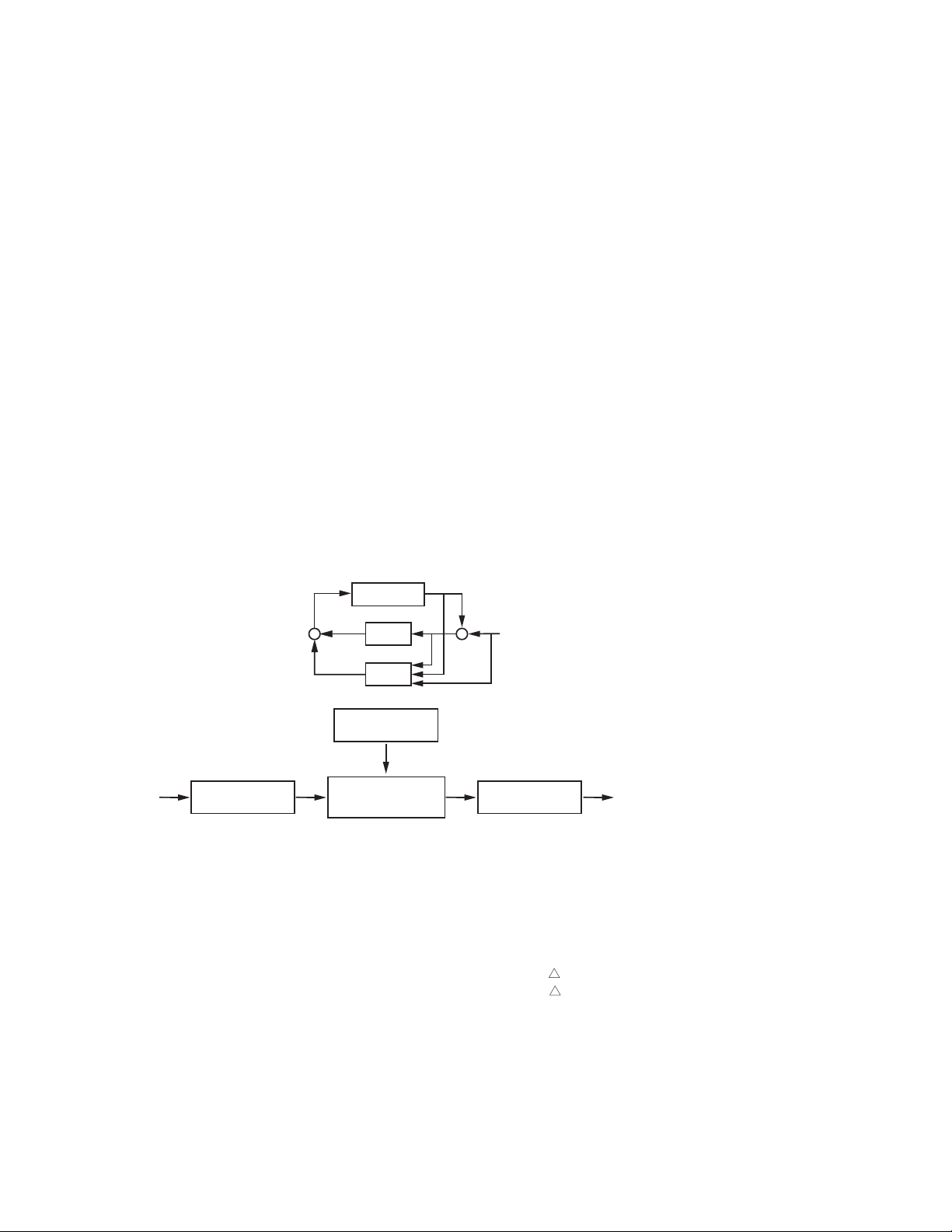
The function of Fuzzy(Smarter) Logic is to adjust the PID parameters internally in order
The function of Fuzzy(Smarter) Logic is to adjust the PID parameters internally in order
manipulate the output value (MV) and adapt to various processes.
to manipulate the output value (MV) and adapt to various processes.
to
The Fuzzy Rule works like this:
The Fuzzy Rule works like this:
temperature difference is large, and temperature rate is large, then MV is large.
If temperature difference is large, and temperature rate is large, then MV is large.
If
temperature difference is large, and temperature rate is small, then MV is small.
If
If temperature difference is large, and temperature rate is small, then MV is small.
FUZZY
Fuzzy Rule
Language
information
Fuzzy Inference
Engine
_
+
SV
DefuzzifierFuzzifier
Digital
information
Figure 1.1
Figure 1.1
Fuzzy PID System Block
Fuzzy
PID System Block
5
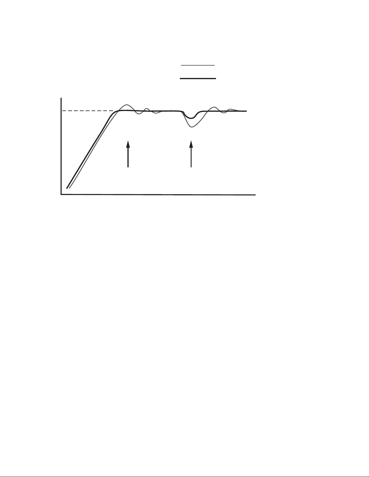
PID + Fuzzy Control has been proven to be an efficient method to improve process
PID + Fuzzy Control has been proven to be an efficient method to improve process
stability as shown by the comparison curves below:
stability
Temperature
Set point
as shown by the comparison curves below:
PID control with properly tuned
PID + Fuzzy control
Warm Up
Load Disturbance
Time
Figure 1.2 Fuzzy PID
Figure 1.2 Fuzzy PID
Enhances Control
Enhances
Stability
Stability
Control
6

1 2 Ordering Code1 2 Ordering Code
ETR-8300-
Power InputPower Input
4: 90 - 264 VAC, 50/60 HZ
4: 90 - 264 VAC, 50/60 HZ
11 - 26 VAC or VDC
5: 11 - 26 VAC or VDC
5:
1 2
Signal InputSignal Input
1: Standard Input
1: Standard Input
1 - Universal Input
Input 1 - Universal Input
Input
- 10V
J, K, T, E, B,
R,
R, S, N, L
Thermocouple:
Thermocouple: J, K, T, E, B,
PT100 DIN, PT100 JIS
RTD:
RTD: PT100 DIN, PT100 JIS
Current:
Current: 4 - 20mA,0-20mA.
Voltage:
Voltage:0-1V,0-5V,1-5V,
2 - CT and Analog Input
Input
Input2-CTandAnalog Input
CT:
CT:0-50Amp. AC Current
Analog
Analog Input:4-20mA,
3 - Event Input ( EI )
Input
Input 3 - Event Input ( EI )
Example
ETR-8300-4111101
ETR-8300-4111101
- 264 operating voltage
90 - 264 operating voltage
90
Standard Input
Input:
Input: Standard Input
Output
Output 1: Relay
Output
Output 2: Relay
Alarm
Alarm 1: Form C Relay
RS-
RS- 485 Communication Interface
1: Relay
2: Relay
1: Form C Relay
485 Communication Interface
4 - 20mA, 0 - 20 mA.
0 - 1V, 0 - 5V, 1 - 5V,
0
0 - 10V
0 - 50 Amp. AC Current
Transformer
Transformer
Input: 4 - 20 mA,
- 20mA, 0 - 1V, 0 - 5V,
0
0 - 20mA,0-1V,0-5V,
- 5V, 0 - 10V.
1
1-5V,0-10V.
S, N, L
**
3 4
Alarm 1Alarm 1
0: None0: None
1: Form C Relay1: Form C Relay
2A / 240VAC2A / 240VAC
Output 1Output 1
0: None
0: None
Relay 2A/240VAC
1: Relay 2A/240VAC
1:
Pulsed voltage to
2:
2: Pulsed voltage to
SSR, 5V/30mA
drive
drive SSR, 5V/30mA
Isolated
3:
3: Isolated
- 20mA / 0 - 20mA
4
4-20mA/0-20mA
Isolated 1 - 5V / 0 - 5V
4:
4: Isolated1-5V/0-5V
Isolated 0 - 10V
5:
5: Isolated0-10V
Triac Output
6:
6: Triac Output
/ 240VAC,SSR
1A
1A / 240VAC,SSR
Pulsed voltage to drive
C:
C: Pulsed voltage to drive
14V / 30mA
SSR
SSR 14V / 30mA
*
5
6
Alarm 2Alarm 2
0: None0: None
1: Relay1: Relay
2A / 240VAC2A / 240VAC
7
Communications
0: None
0: None
RS-485
1: RS-485
1:
RS-232
2:
2: RS-232
Retransmit 4-20mA
3:
3: Retransmit 4-20mA
/0-20mA
/0-20mA
Retransmit 1 - 5V
4:
4: Retransmit1-5V
0 - 5V
/
/0-5V
Retransmit 0 - 10V
5:
5: Retransmit0-10V
*
*
Output 2Output 2
0: None
0: None
Relay 2A/240VAC
1: Relay 2A/240VAC
1:
Pulsed voltage to
2:
2: Pulsed voltage to
SSR, 5V / 30mA
drive
drive SSR, 5V / 30mA
Isolated 4 - 20mA / 0 - 20mA
3:
3: Isolated4-20mA/0-20mA
*
**
Isolated 1 - 5V / 0 - 5V
4:
4: Isolated1-5V/0-5V
Isolated 0 - 10V
5:
5: Isolated0-10V
Triac Output, 1A / 240VAC, SSR
6:
6: Triac Output, 1A / 240VAC, SSR
Isolated 20V / 25mA DC
7:
7: Isolated 20V / 25mA DC
Output
Output Power Supply
Isolated 12V / 40 mA DC
8:
8: Isolated 12V / 40 mA DC
Output
Output Power Supply
Isolated 5V / 80mA DC
9:
9: Isolated 5V / 80mA DC
Output
Output Power Supply
Pulsed voltage 14V / 30mA
C:
C: Pulsed voltage 14V / 30mA
Range set by front keyboard
Range set by front keyboard
*
Need to order an accessory CT94-1 if
Need
Heater
Heater Break detection is required.
Power Supply
Power Supply
Power Supply
to order an accessory CT94-1 if
Break detection is required.
*
*
Accessories
CT94-1 =0-50Amp. AC Current Transformer
CT94-1 = 0 - 50 Amp. AC Current Transformer
OM95-3 = Isolated4-20mA/0-20mAAnalog Output Module
OM95-3
OM95-4
OM95-4 = Isolated1-5V/0-5VAnalog Output Module
OM95-5
OM95-5 = Isolated 0 - 10V Analog Output Module
OM94-6
OM94-6 = Isolated 1A / 240VAC Triac Output Module ( SSR )
DC94-1
DC94-1 = Isolated 20V / 25mA DC Output Power Supply
DC94-2
DC94-2 = Isolated 12V / 40mA DC Output Power Supply
DC94-3
DC94-3 = Isolated 5V / 80mA DC Output Power Supply
CM94-1
CM94-1 = Isolated RS-485 Interface Module
CM94-2
CM94-2 = Isolated RS-232 Interface Module
CM94-3
CM94-3 = Isolated4-20mA/0-20mARetransmission Module
CM94-4
CM94-4 = Isolated1-5V/0-5VRetransmission Module
CM94-5
CM94-5 = Isolated 0 - 10V Retransmission Module
CC94-1
CC94-1 = RS-232 Interface Cable (2M)
=
= ETR-8300 User's Manual
= Isolated 4 - 20 mA / 0 - 20 mA Analog Output Module
= Isolated 1 - 5V / 0 - 5V Analog Output Module
= Isolated 0 - 10V Analog Output Module
= Isolated 1A / 240VAC Triac Output Module ( SSR )
= Isolated 20V / 25mA DC Output Power Supply
= Isolated 12V / 40mA DC Output Power Supply
= Isolated 5V / 80mA DC Output Power Supply
= Isolated RS-485 Interface Module
= Isolated RS-232 Interface Module
= Isolated 4 - 20 mA / 0 - 20 mA Retransmission Module
= Isolated 1 - 5V / 0 - 5V Retransmission Module
= Isolated 0 - 10V Retransmission Module
= RS-232 Interface Cable (2M)
ETR-8300 User's Manual
Related ProductsRelated Products
P12A = Hand-held Programmer for ETR
P12A = Hand-held Programmer for ETR
Controller
Series Controller
Series
SNA10A = Smart Network Adaptor for Third
SNA10A = Smart Network Adaptor for Third
Software, Converts 255
Party Software, Converts 255
Party
channels
channels of RS-485 or RS-422 to
RS-232
RS-232 Network
SNA10B = Smart Network Adaptor for BC-Net
SNA10B = Smart Network Adaptor for BC-Net
Software, Converts 255 channels
Software,
RS-485 or RS-422 to RS-232
of
of RS-485 or RS-422 to RS-232
Network
Network
VPFW20
VPFW20 = 20 Amp. Variable Period Full
VPFW50
VPFW50 = 50 Amp. Variable Period Full
VPFW100
VPFW100 =100 Amp. Variable Period Full
= 20 Amp. Variable Period Full
Wave
Wave SSR AC Power Module
= 50 Amp. Variable Period Full
Wave
Wave SSR AC Power Module
=100 Amp. Variable Period Full
Wave
Wave SSR AC Power Module
of RS-485 or RS-422 to
Network
Converts 255 channels
SSR AC Power Module
SSR AC Power Module
SSR AC Power Module
7
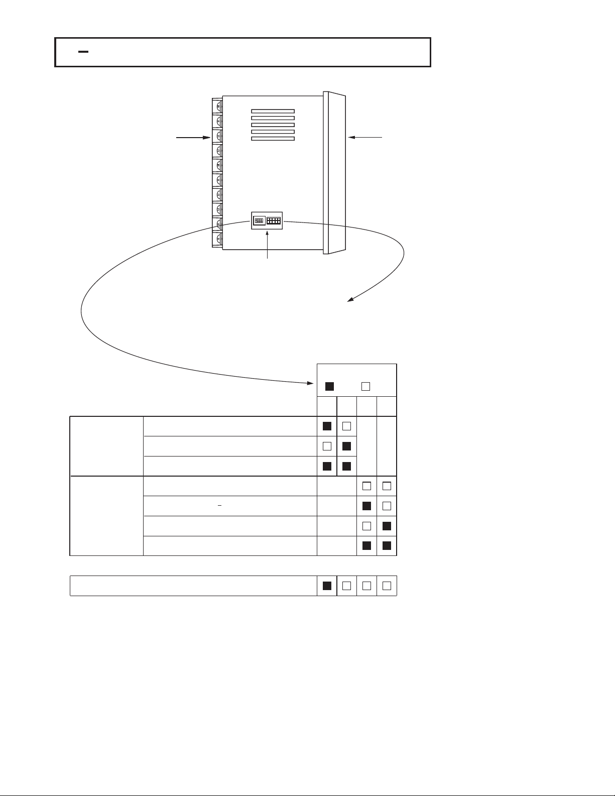
1 3 Programming Port and DIP Switch1 3 Programming Port and DIP Switch
Rear
Terminal
ONDIP
1234
Access Hole
The programming port is used to connect to
The programming port is used to connect to
P12A hand-held programmer for automatic
the P12A hand-held programmer for automatic
the
programming,
programming, also can be connected to ATE
system
system for automatic testing & calibration.
for automatic testing & calibration.
also can be connected to ATE
DIP SwitchDIP Switch
12
TC, RTD, mV
:ON :OFF
34
Front
Panel
Figure 1.3 Access Hole
Figure 1.3 Access Hole
Overview
Overview
Input 1
Input 1
Select
Select
0-1V, 0-5V, 1-5V, 0-10V
0-20 mA, 4-20 mA
All parameters are Unlocked
Only SP1, SEL1 SEL5 are unlocked
*
Lockout
Only SP1 is unlocked
All Parameters are locked
Factory Default SettingFactory Default Setting
The programming port is used for off-line automatic setup and testing
The programming port is used for off-line automatic setup and testing
procedures only. Don't attempt to make any connection to these pins when the
procedures only. Don't attempt to make any connection to these pins when the
unit is used for a normal control purpose.
unit is used for a normal control purpose.
When the unit leaves the factory, the DIP switch is set so that TC & RTD are selected for input
When the unit leaves the factory, the DIP switch is set so that TC & RTD are selected for input
1 and all parameters are unlocked.
1 and all parameters are unlocked.
Lockout function is used to disable the adjustment of parameters as well as operation of
Lockout function is used to disable the adjustment of parameters as well as operation of
calibration mode. However, the menu can still be viewed even under lockout condition.
calibration
SEL1- SEL5 represent those parameters which are selected by using SEL1, SEL2,...SEL5
SEL1- SEL5 represent those parameters which are selected by using SEL1, SEL2,...SEL5
*
parameters contained in the Setup menu. Parameters selected are then allocated at the
parameters contained in the Setup menu. Parameters selected are then allocated at the
beginning of the user menu.
beginning of the user menu.
mode. However, the menu can still be viewed even under lockout condition.
Table 1.1 DIP Switch
Table 1.1 DIP Switch
Configuration
Configuration
8
1 4 Keys and Displays1 4 Keys and Displays
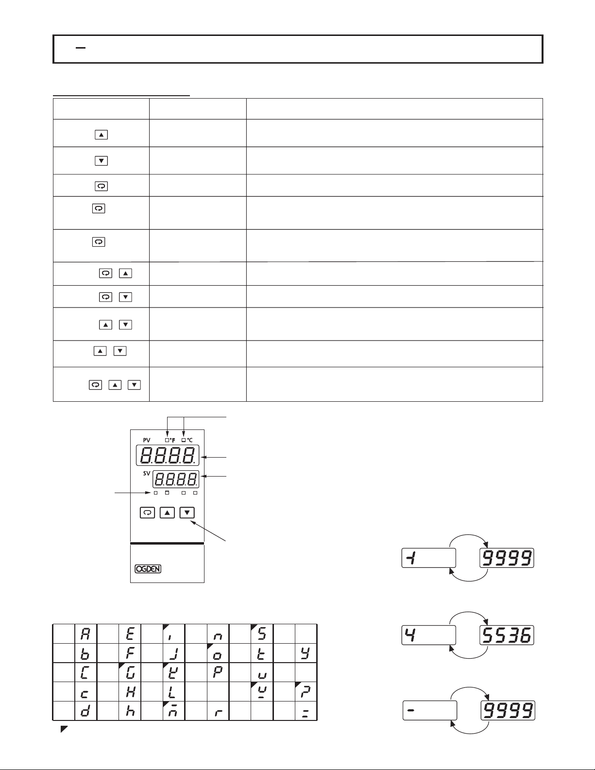
The unit is programmed by using three keys on the front panel. The available key functions are listed in following table.The unit is programmed by using three keys on the front panel. The available key functions are listed in following table.
Table 1.2 Keypad OperationTable 1.2 Keypad Operation
TOUCHKEYS FUNCTION DESCRIPTION
Press
for at least 3 seconds
Press
for at least 6 seconds
Press
Press
Press
Press
for at least 3 seconds
Press
Up Key
Down Key
Scroll Key
Enter Key
Start Record Key
Reverse Scroll Key
Mode Key
Reset Key
Sleep Key
Factory Key
Press and release quickly to increase the value of parameter.
Press and hold to accelerate increment speed.
Press and release quickly to decrease the value of parameter.
Press and hold to accelerate decrement speed.
Select the parameter in a direct sequence.
Allow access to more parameters on user menu, also used to Enter manual
mode, auto-tune mode, default setting mode and to save calibration data
during calibration procedure.
Reset historical values of PVHI and PVLO and start to record the peak process
value.
Select the parameter in a reverse sequence during menu scrolling.
Select the operation Mode in sequence.
Reset the front panel display to a normal display mode, also used to leave
the specific Mode execution to end up the auto-tune and manual control
execution, and to quit the sleep mode.
The controller enters the sleep mode if the sleep function ( SLEP ) is enabled
( select YES ).
By entering correct security code to allow execution of engineering programs.
This function is used only at the factory to manage the diagnostic reports.
The user should never attempt to operate this function.
Output 1 IndicatorOutput 1 Indicator
Output 2 IndicatorOutput 2 Indicator
Alarm 1 IndicatorAlarm 1 Indicator
Alarm 2 IndicatorAlarm 2 Indicator
Out1 Out2 Alm1 Alm2
ETR-8300
Figure 1.4 Front Panel DescriptionFigure 1.4 Front Panel Description
Table 1.3 Character LegendTable 1.3 Character Legend
A
B
C
c
Dh
: Characters displayed with symbols: Characters displayed with symbols
E
F
G
H
I
J
K
L
M
N
O
P
Q
R
Process Unit IndicatorProcess Unit Indicator
Upper Display,
Upper Display,
display process value,
to display process value,
to
symbol and error code etc.
menu
menu symbol and error code etc.
Lower Display,
Lower Display,
display set point value,
to display set point value,
to
parameter
parameter value or control
output
output value etc.
3 Buttons for ease of control
3 Buttons for ease of control
setup and set point adjustment.
setup
S
T
U
V
W
value or control
value etc.
and set point adjustment.
X
Y
Z
?
=
How to display a 5-digit number ?How to display a 5-digit number ?
For a number with decimal point the
For a number with decimal point the
display will be shifted one digit right:
display
-199.99 will be displayed by -199.9
-199.99 will be displayed by -199.9
4553.6 will be displayed by 4553
4553.6
For a number without decimal point
For a number without decimal point
the display will be divided into two
the
alternating
alternating phases:
-19999 will be displayed by:-19999 will be displayed by:
45536 will be displayed by:45536 will be displayed by:
-9999 will be displayed by:-9999 will be displayed by:
will be shifted one digit right:
will be displayed by 4553
display will be divided into two
phases:
9
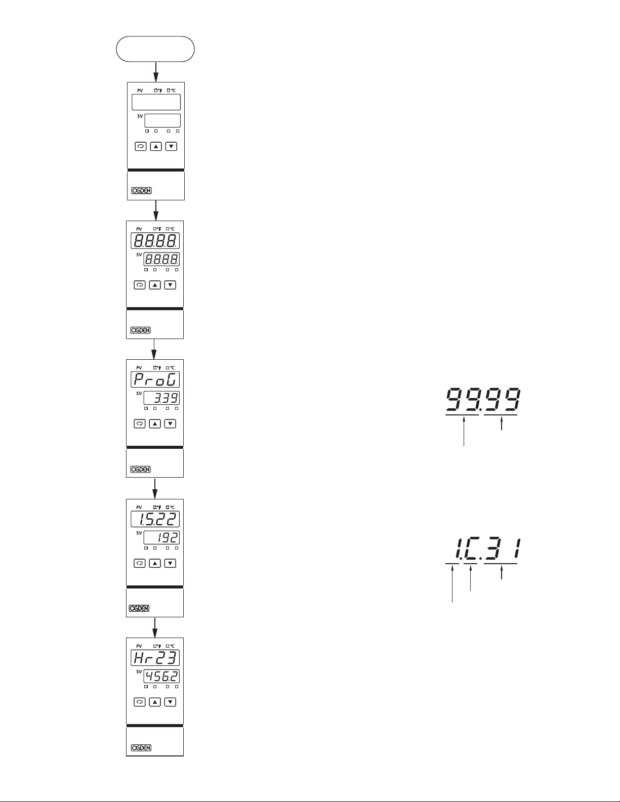
Power OnPower On
Out1 Out2 Alm1 Alm2
ETR-8300
All segments of display and
All segments of display and
indicators are left off for 0.5
indicators
second.
second.
are left off for 0.5
Figure 1.5 Display Sequence of
Figure 1.5 Display Sequence of
Message
Initial Message
Initial
Out1 Out2 Alm1 Alm2
ETR-8300
Out1 Out2 Alm1 Alm2
ETR-8300
Out1 Out2 Alm1 Alm2
ETR-8300
All segments of display and
All segments of display and
indicators are lit for 2 seconds.
indicators
Display program code of the
Display program code of the
product for 2.5 seconds.
product
The left diagram shows program
The left diagram shows program
no. 3 ( for ETR-8300 ) with version
no.
39.
39.
Display Date Code and Serial
Display Date Code and Serial
number for 2.5 seconds.
number
The left diagram shows Year 2001,
The left diagram shows Year 2001,
Month May(5),Date 22'nd and
Month
Serial
Serial number 192. This means that
the
the product is the 192 'nd unit
produced
produced on May 22'nd, 2001.
Note
Note that the month code stands for
October,
October, B November C
stands
stands for .
are lit for 2 seconds.
for 2.5 seconds.
3 ( for ETR-8300 ) with version
for 2.5 seconds.
May ( 5 ), Date 22'nd and
number 192. This means that
product is the 192 'nd unit
on May 22'nd, 2001.
that the month code stands for
B November C
stands
stands for and
for .
December
December
for and
A
A
Program CodeProgram Code
Program VersionProgram Version
Program No.Program No.
Date CodeDate Code
Date (31'st)Date (31'st)
Month (December)Month (December)
Year (2001)Year (2001)
10
Out1 Out2 Alm1 Alm2
ETR-8300
Display the used hours for 2.5
Display the used hours for 2.5
seconds.
seconds.
The left diagram shows that the
The left diagram shows that the
has been used for 23456.2
unit has been used for 23456.2
unit
since production.
hours
hours since production.
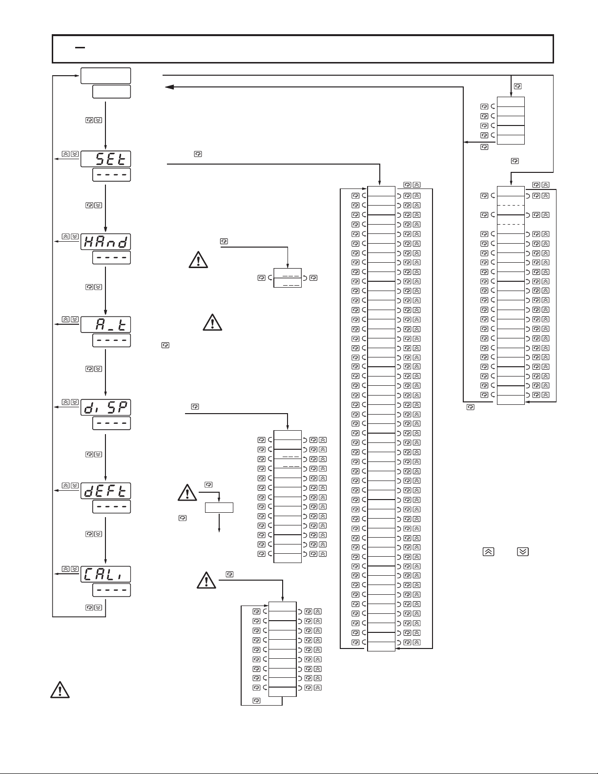
1 5 Menu Overview1 5 Menu Overview
User
PV Value
SV Value
User
Menu
Menu
*2
SEL1
SEL2
SEL3
SEL4
SEL5
Setup
Setup
Menu
Menu
Hand (Manual)
Hand (Manual)
Control
Control
Mode
Mode
Auto-tuning
Auto-tuning
Mode
Mode
Press for 3 seconds to enter
the auto-tuning mode
Display
Display
Mode
Mode
Default
Default
Setting
Setting
Mode
Mode
3 seconds
Calibration
Calibration
Mode
Mode
Entering these modes will break the control
Entering these modes will break the control
and change some of the previous
loop and change some of the previous
loop
data. Make sure that the system will
setting
setting data. Make sure that the system will
stable without the controller if these
be
be stable without the controller if these
are accessed.
modes
modes are accessed.
FILE
for
To execute the
default setting
program
for 3 seconds
H
C
PVHI
PVLO
H
C
DV
PV1
PV2
PB
TI
TD
CJCT
PVR
PVRH
PVRL
AD0
ADG
V1G
CJTL
CJG
REF1
SR1
MA1G
V2G
MA2G
*1
FUNC
COMM
PROT
ADDR
BAUD
DATA
PARI
STOP
AOFN
AOLO
AOHI
IN1
IN1U
DP1
IN1L
IN1H
IN2
IN2U
DP2
IN2L
IN2H
OUT1
O1TY
CYC1
O1FT
OUT2
O2TY
CYC2
O2FT
A1FN
A1MD
A1FT
A2FN
A2MD
A2FT
EIFN
PVMD
FILT
SELF
SLEP
SPMD
SP1L
SP1H
SP2F
SEL1
SEL2
SEL3
SEL4
SEL5
*1:
The flow chart shows a complete listing of all parameters.
The flow chart shows a complete listing of all parameters.
actual application the number of available parameters
For actual application the number of available parameters
For
depends
depends on setup conditions, and should be less
than
than that shown in the flow chart. See for the
existence
existence conditions of each parameter.
You can select at most 5 parameters put in front of the user
You can select at most 5 parameters put in front of the user
*2:
menu by using SEL1 to SEL5 contained at the bottom of
menu by using SEL1 to SEL5 contained at the bottom of
setup menu.
setup menu.
on setup conditions, and should be less
that shown in the flow chart. See for the
conditions of each parameter.
Display ReturnDisplay Return
The menu will revert to the
The menu will revert to the
PV/SV display after
PV/SV
except
except when in the
Manual Mode Menus
or
or Manual Mode Menus
However,
However, the menu will
revert
revert back to the PV / SV
display
display at any time by
pressing
pressing and .
*1
TIME
A1SP
A1DV
A2SP
A2DV
RAMP
OFST
REFC
SHIF
PB1
TI1
TD1
CPB
DB
SP2
PB2
TI2
TD2
O1HY
A1HY
A2HY
PL1
PL2
display after
when in the
the menu will
back to the PV / SV
at any time by
and .
Appendix
Appendix A-1
A-1
for 3
seconds
minutes
2
2 minutes
Display
Display
.
.
11
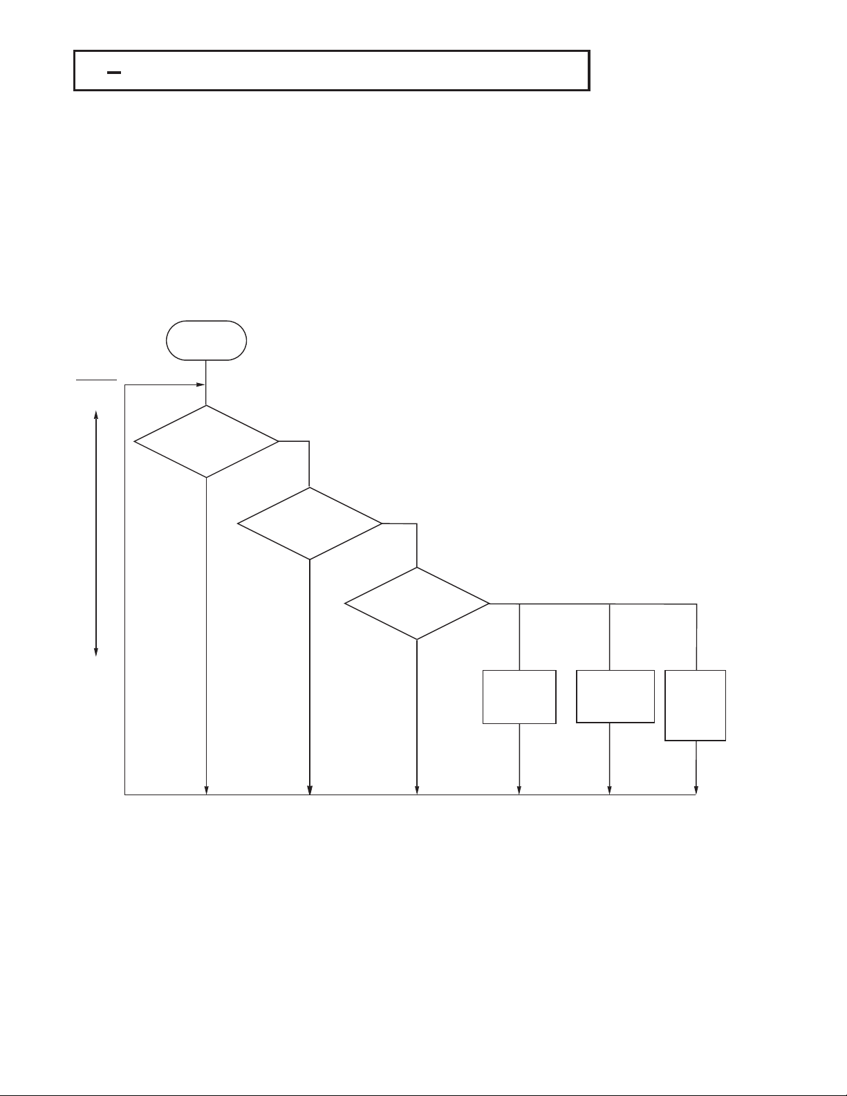
1 6 System Modes1 6 System Modes
The controller performs close loop control under its normal control mode condition.
The controller performs close loop control under its normal control mode condition.
controller will maintain its normal control mode when you are operating user menu,
The controller will maintain its normal control mode when you are operating user menu,
The
menu or display mode, reloading default values or applying an event input
setup
setup menu or display mode, reloading default values or applying an event input
signal.
signal. Under certain conditions the control will transfer to an . The
exception
exception modes include :
Mode Auto-tuning
Mode Auto-tuning Mode.
the
the auto-tuning mode which performs ON-OFF plus PID close loop control. The mode
transfer
transfer is governed by the priority conditions. A lower priority mode can not alter a
higher
higher priority mode, as shown in Figure 1.6.
Under certain conditions the control will transfer to an . The
modes include :
and All
and All these modes perform in an open loop control except
auto-tuning mode which performs ON-OFF plus PID close loop control. The mode
is governed by the priority conditions. A lower priority mode can not alter a
priority mode, as shown in Figure 1.6.
Priority
High
Mode.
? Mode? Mode
Mode, Manual Mode, Failure Mode, Calibration
Sleep
Sleep Mode, Manual Mode, Failure Mode, Calibration
these modes perform in an open loop control except
Exception Mode
Exception Mode
System Modes
System Modes
Mode :
Sleep Mode :
Sleep
Section 4-11.
See
See Section 4-11.
Manual
Manual Mode :
See
See Section 3-22.
Failure
Failure Mode :
See
See Section 3-16.
Calibration
Calibration Mode :
See
See Chapter 6.
Auto-tuning
Auto-tuning Mode :
See
See Section 3-19.
Normal
Normal Control Mode :
See
See Section 3-23, 3-25, 4-1
Mode :
Section 3-22.
Mode :
Section 3-16.
Mode :
Chapter 6.
Mode :
Section 3-19.
Control Mode :
Section 3-23, 3-25, 4-1
Low
Sleep Mode?Sleep Mode?
Yes
No
Manual Mode?Manual Mode?
Yes
No
Failure Mode?Failure Mode?
Yes
No
Request
Request
Calibration
Calibration
Mode
Mode
Figure 1.6
Figure 1.6
System Mode Priority
System
Request
Request
Auto-tuning
Auto-tuning
Mode
Mode
Mode Priority
Request
Request
Normal
Normal
Control
Control
Mode
Mode
The calibration mode, auto-tuning mode and normal control mode are in the same
The calibration mode, auto-tuning mode and normal control mode are in the same
priority level. The sleep mode is in the highest priority.
priority
level. The sleep mode is in the highest priority.
12
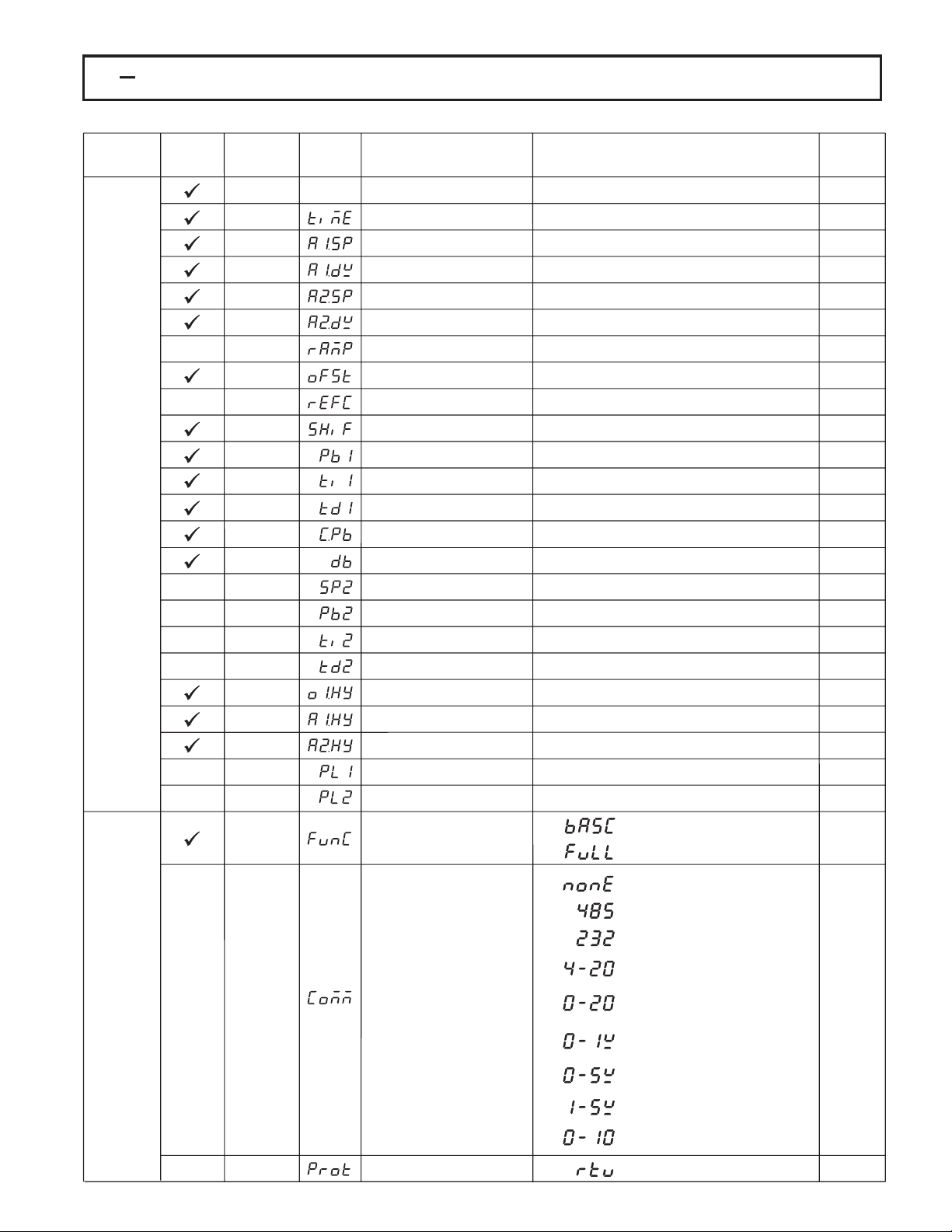
1 7 Parameter Description1 7 Parameter Description
Table 1.4 Parameter DescriptionTable 1.4 Parameter Description
Display
Contained
Contained
in
in
Menu
Basic
Basic
Function
Function
Parameter
Parameter
Notation
Notation
SP1
TIME
A1SP
A1DV
A2SP
A2DV
RAMP
OFST
REFC
SHIF
PB1
TI1User
TD1
CPB
DB
SP2
PB2
TI2
TD2
O1HY
A1HY
A2HY
PL1
PL2
FUNC
Display
Format
Format
Set point 1
Dwell Time
Alarm 1 Set point
Alarm 1 Deviation Value
Alarm 2 Set point
Alarm 2 Deviation Value
Ramp Rate
Offset Value for P control
Reference Constant for
Specific Function
PV1 Shift (offset) Value
Proportional Band 1 Value
Integral Time 1 Value
Derivative Time 1 Value
Cooling Proportional Band
Value
Heating-Cooling Dead Band
Negative Value= Overlap
Set point 2
Proportional Band 2 Value
Integral Time 2 Value
Derivative Time 2 Value
Output 1 ON-OFF Control
Hysteresis
Hysteresis Control of Alarm 1
Hysteresis Control of Alarm 2
Output 1 Power Limit
Output 2 Power Limit
Function Complexity Level
Parameter
Parameter
Description
Description
Low:
Low:
See Table 1.5, 1.6
Low:
See Table 1.5, 1.7
Low:
Low:
Low:
Low:
Low:
Low:
Low:
Low:
Low:
Low:
See Table 1.5, 1.8
Low:
Low:
Low:
Low:
Low:
Low:
Low:
Low:
0
1
SP1L SP1H
0 6553.5 minutes 0.0
-200.0 °C
(-360.0 °F)
-200.0 °C
(-360.0 ° F)L
0 0.0
0
0
-200.0 °C
(-360.0 °F)
0
0
0
1
-36.0
0
0
0
0.1
0.1
0.1
0
0
:
Basic Function Mode
Full Function Mode
:
Range
High:
High:
High:
High:
High:
High:
High:
High:
High:
High:
High:
High:
High:
High:
High:
High:
High:
High:
High:
High:
High:
200.0 °C
( 360.0 °F)
200.0 °C
( 360.0 °F)
500.0 °C
(900.0 °F)
100.0 %
60
200.0 °C
( 360.0 °F)
500.0 °C
(900.0 °F)
1000 sec
360.0 sec
255 %
36.0 %
500.0 °C
(900.0 °F)
1000 sec
360.0 sec
55.6 °C
( 100.0 °F)
10.0 °C
(18.0 °F)
10.0 °C
(18.0 °F)
100 %
100 %
Default
Default
Value
Value
100.0 °C
(212.0 °F)
100.0 °C
(212.0 °F)
10.0 °C
(18.0 °F)
100.0 °C
(212.0 °F)
10.0 °C
(18.0 °F)
25.0
2
0.0
10.0 °C
(18.0 °F)
100
25.0
100
0
37.8 °C
(100.0 °F)
10.0 °C
(18.0 °F)
100
25.0
0.1
0.1
0.1
100
100
1
Setup
Menu
COMM
PROT
Communication Interface
Type
COMM Protocol Selection
:
0
1
2
3
4
5
6
7
8
0
No communication function
:
RS-485 interface
:
RS-232 interface
:
4 - 20 mA analog retransmission
output
:
0 - 20 mA analog retransmission
output
:
0 - 1V analog retransmission
output
:
0 - 5V analog retransmission
output
:
1 - 5V analog retransmission
output
:
0 - 10V analog retransmission
output
Modbus protocol RTU mode
:
1
0
13
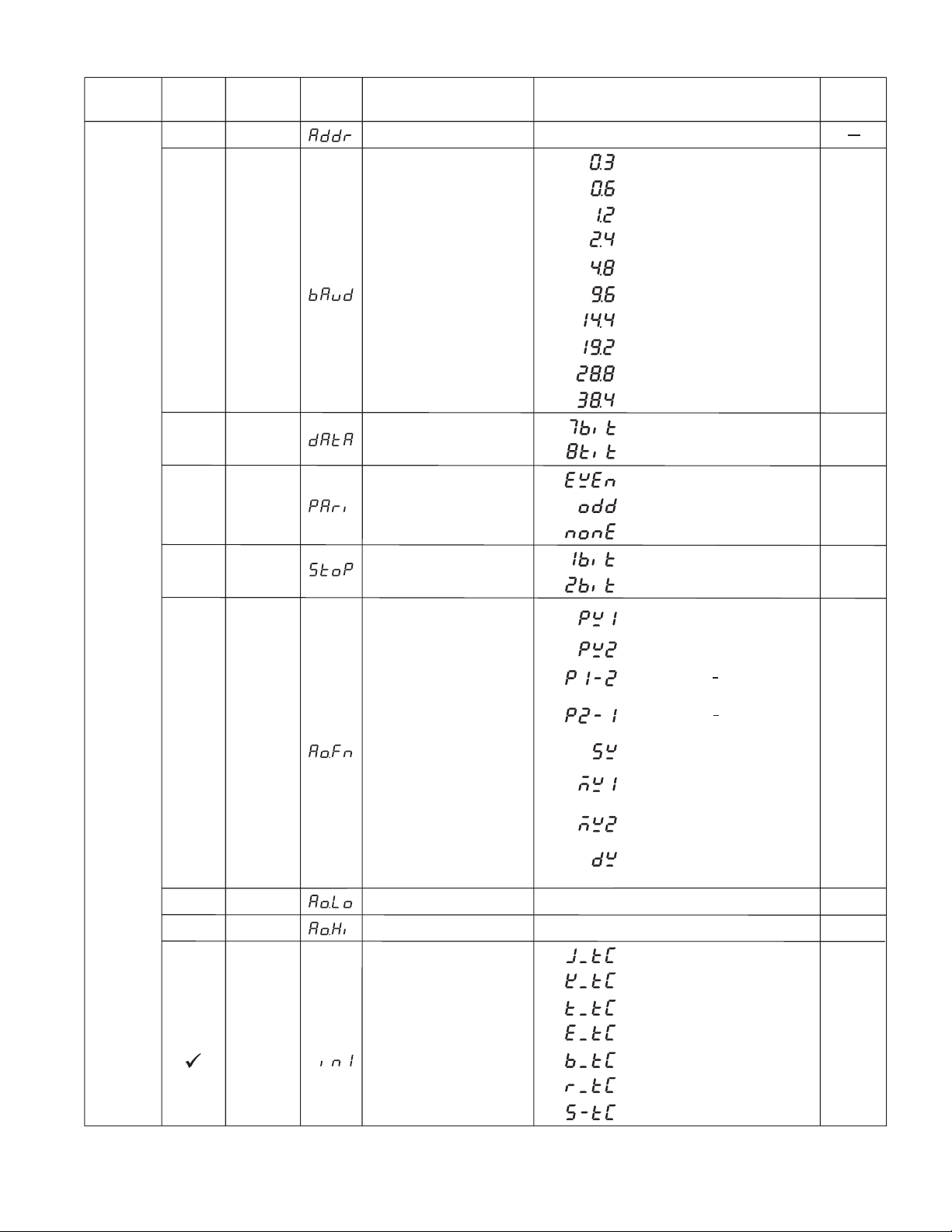
Table 1.4 Parameter Description ( continued 2/7 )Table 1.4 Parameter Description ( continued 2/7 )
Parameter
Contained
Contained
in
in
Basic
Basic
Function
Function
Parameter
Parameter
Notation
Notation
ADDR
BAUD
DATA
PARI
Display
Display
Format
Format
Address Assignment of Digital
COMM
Baud Rate of Digital COMM
Data Bit count of Digital
COMM
Parity Bit of Digital COMM
Parameter
Description
Description
Range
1 255
Low:
:
0
1
2
3
4
5
6
7
8
9
0
1 8 data bits
0
1
2
0.3 Kbits/s baud rate
:
0.6 Kbits/s baud rate
:
1.2 Kbits/s baud rate
:
2.4 Kbits/s baud rate
:
4.8 Kbits/s baud rate
:
9.6 Kbits/s baud rate
:
14.4 Kbits/s baud rate
:
19.2 Kbits/s baud rate
:
28.8 Kbits/s baud rate
:
38.4 Kbits/s baud rate
:
7 data bits
:
Even parity
:
Odd parity
:
No parity bit
:
High:
Default
Default
Value
Value
5
1
0
Setup
Menu
STOP
AOFN
AOLO
AOHI
IN1
Stop Bit Count of Digital
COMM
Analog Output Function
Analog Output Low Scale
Value
Analog Output High Scale
Value
IN1 Sensor Type Selection
0
1
0
1
2
3
4
5
6
7
Low:
Low:
0
1
2
3
4
5
6
:
One stop bit
:
Two stop bits
:
Retransmit IN1 process value
:
Retransmit IN2 process value
:
Retransmit IN1 IN2 difference
process value
:
Retransmit IN2 IN1 difference
process value
:
Retransmit set point value
:
Retransmit output 1 manipulation
value
:
Retransmit output 2 manipulation
value
:
Retransmit deviation(PV-SV)
Value
-19999
-19999
J type thermocouple
:
:
K type thermocouple
T type thermocouple
:
:
E type thermocouple
:
B type thermocouple
:
R type thermocouple
:
S type thermocouple
High:
High:
45536
45536
0
0
0°C
(32.0 °F)
100.0 °C
(212.0 °F)
1
(0)
14
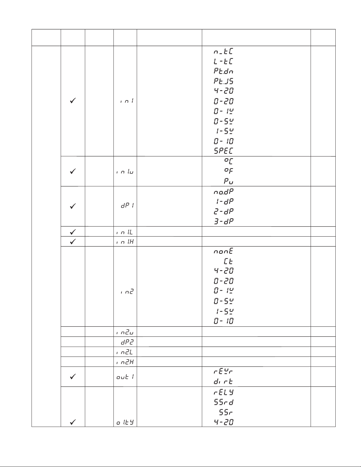
Table 1.4 Parameter Description ( continued 3/7 )Table 1.4 Parameter Description ( continued 3/7 )
Parameter
Contained
Contained
in
in
Setup
Menu
Basic
Basic
Function
Function
Parameter
Parameter
Notation
Notation
IN1
IN1U
DP1
IN1L
IN1H
IN2
Display
Display
Format
Format
IN1 Sensor Type Selection
IN1 Unit Selection
IN1 Decimal Point Selection
IN1 Low Scale Value
IN1 High Scale Value
IN2 Signal Type Selection
Parameter
Description
Description
7
8
9
10
11
12
13
14
15
16
17
0
1
2
0
1
2
3
Low:
Low:
0
1
2
3
4
5
6
7
-19999
-19999
Range
:
N type thermocouple
:
L type thermocouple
:
PT 100 ohms DIN curve
:
PT 100 ohms JIS curve
:
4 - 20 mA linear current input
:
0 - 20 mA linear current input
:
0 - 1V linear Voltage input
:
0 - 5V linear Voltage input
:
1 - 5V linear Voltage input
:
0 - 10V linear Voltage input
:
Special defined sensor curve
:
Degree C unit
:
Degree F unit
:
Process unit
:
No decimal point
:
1 decimal digit
:
2 decimal digits
:
3 decimal digits
High:
45536
High:
45536
:
IN2 no function
:
Current transformer input
:
4 - 20 mA linear current input
:
0 - 20 mA linear current input
:
0 - 1V linear voltage input
:
0 - 5V linear voltage input
:
1 - 5V linear voltage input
:
0 - 10V linear voltage input
Default
Value
1
(0)
0
(1)
1
0
1000
1
IN2U
DP2
IN2L
IN2H
OUT1
O1TY
IN2 Unit Selection
IN2 Decimal Point Selection
IN2 Low Scale Value
IN2 High Scale Value
Output 1 Function
Output 1 Signal Type
Same as IN1U
Same as DP1
-19999
Low:
-19999
Low:
0
1
0
1
2
3
High:
45536
High:
45536
:
Reverse (heating ) control action
:
Direct (cooling) control action
Relay output
:
Solid state relay drive output
:
Solid state relay output
:
:
4 - 20 mA current module
2
1
0
1000
0
0
15

Table 1.4 Parameter Description ( continued 4/7 )Table 1.4 Parameter Description ( continued 4/7 )
Parameter
Contained
Contained
in
in
Basic
Basic
Function
Function
Parameter
Parameter
Notation
Notation
O1TY
CYC1
Display
Display
Format
Format
Output 1 Signal Type
Output 1 Cycle Time
Parameter
Description
Description
4
5
6
7
8
Low:
Range
:
0 - 20 mA current module
0 - 1V voltage module
:
0 - 5V voltage module
:
1 - 5V voltage module
:
0 - 10V voltage module
:
0.1
High:
100.0 sec 18.0
Default
Default
Value
Value
0
Setup
Menu
O1FT
OUT2
O2TY
CYC2
O2FT
A1FN
Output 1 Failure Transfer
Mode
Output 2 Function
Output 2 Signal Type
Output 2 Cycle Time
Output 2 Failure Transfer
Mode
Alarm 1 Function
Select BPLS ( bumpless transfer ) or 0.0 ~ 100.0
% to continue output 1 control function as the unit
fails, power starts or manual mode starts.
0
1
3
Same as O1TY
Low:
Select BPLS ( bumpless transfer ) or 0.0 ~ 100.0
% to continue output 2 control function as the unit
fails, power starts or manual mode starts.
0
1
2
3
4
5
6
7 IN1 process value low alarm
8 IN2 process value high alarm
9
10
11
12
13
14 Loop break alarm
15 Sensor break or A-D fails
: Output 2 no function
: PID cooling control
: DC power supply module
installed
0.1
:
No alarm function
:
Dwell timer action
:
Deviation high alarm
:
Deviation low alarm
:
Deviation band out of band alarm
:
Deviation band in band alarm
:
IN1 process value high alarm
:
:
:
IN2 process value low alarm
IN1 or IN2 process value high
:
alarm
:
IN1 or IN2 process value low
alarm
:
IN1 IN2 difference process value
high alarm
:
IN1 IN2 difference process value
low alarm
:
:
High:
100.0 sec
BPLS
0
0
18.0
BPLS
2
16
A1MD
Alarm 1 Operation Mode
0
1
2
3
:
Normal alarm action
Latching alarm action
:
:
Hold alarm action
Latching & actionHold
:
0
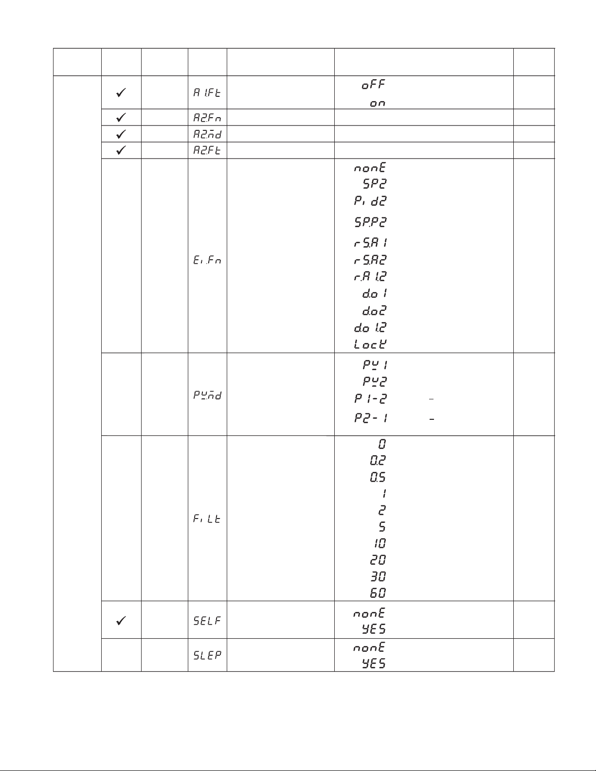
Table 1.4 Parameter Description ( continued 5/7 )Table 1.4 Parameter Description ( continued 5/7 )
Parameter
Contained
Contained
in
in
Basic
Basic
Function
Function
Parameter
Parameter
Notation
Notation
A1FT
A2FN
A2MD
A2FT
Display
Display
Format
Format
Alarm 1 Failure Transfer
Mode
Alarm 2 Function
Alarm 2 Operation Mode
Alarm 2 Failure Transfer
Mode
Parameter
Description
Description
Range
:
0
1
Same as A1FN
Same as A1MD
Same as A1FT
0
1 SP2 activated to replace SP1
2
3
4
Alarm output OFF as unit fails
:
Alarm output ON as unit fails
Event input no function
:
:
PB2, TI2, TD2 activated to replace
:
PB1, TI1, TD1
:
SP2, PB2, TI2, TD2 activated to
replace SP1, PB1, TI1, TD1
Reset alarm 1 output
:
Default
Default
Value
Value
1
2
0
1
Setup
Menu
EIFN
PVMD
FILT
Event Input Function
PV Mode Selection
Filter Damping Time
Constant of PV
10
:
5
6
7
8
9
0
1
2
3
0
1
2
3
4
5
6
7
8
9
Reset alarm 2 output
:
Reset alarm 1 & alarm 2
Disable Output 1
:
Disable Output 2
:
Disable Output 1 & Output 2
:
:
Lock All Parameters
:
Use PV1 as process value
:
Use PV2 as process value
:
Use PV1 PV2 (difference) as
process value
:
Use PV2 PV1 (difference) as
process value
:
0 second time constant
:
0.2 second time constant
:
0.5 second time constant
:
1 second time constant
:
2 seconds time constant
:
5 seconds time constant
:
10 seconds time constant
:
20 seconds time constant
:
30 seconds time constant
:
60 seconds time constant
1
0
2
SELF
SLEP
Self Tuning Function
Selection
Sleep mode Function
Selection
0
1
0
1
:
Self tune function disabled
:
Self tune function enabled
:
Sleep mode function disabled
:
Sleep mode function enabled
0
0
17
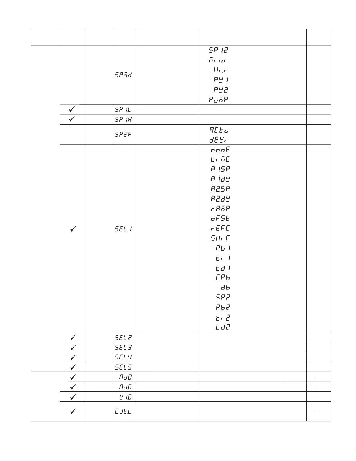
Table 1.4 Parameter Description ( continued 6/7 )Table 1.4 Parameter Description ( continued 6/7 )
Parameter
Contained
Contained
in
in
Basic
Basic
Function
Function
Display
Parameter
Parameter
Notation
Notation
SPMD Set point Mode Selection
SP1L
SP1H
SP2F
Display
Format
Format
SP1 Low Scale Value
SP1 High Scale Value
Format of set point 2 Value
Parameter
Description
Description
0
1
2
3
4
5
Low:
Low:
0
1
0
1
2
3
Range
Use SP1 or SP2 (depends on EIFN)
:
as set point
Use minute ramp rate as set point
:
Use hour ramp rate as set point
:
Use IN1 process value as set point
:
Use IN2 process value as set point
:
Selected for pump control
:
-19999
-19999
set point 2 (SP2) is an actual value
:
set point 2 (SP2) is a deviation
:
value
No parameter put ahead
:
:
Parameter TIME put ahead
:
Parameter A1SP put ahead
:
Parameter A1DV put ahead
High:
High:
45536
45536
Default
Default
Value
Value
0
0°C
(32.0 °F)
1000.0 °C
(1832.0 °F)
0
Setup
Menu
Calibration
Mode
Menu
SEL1 Select 1'st Parameter
SEL2
SEL3
SEL4
SEL5
AD0
ADG
V1G
CJTL
Select 2'nd Parameter
Select 3'rd Parameter
Select 4'th Parameter
Select 5'th Parameter
A to D Zero Calibration
Coefficient
A to D Gain Calibration
Coefficient
Voltage Input 1 Gain
Calibration Coefficient
Cold Junction Low
Temperature Calibration
Coefficient
4
5
6
7
8
9
10
11
12
13
14
15
16
17
18
Same as SEL1
Same as SEL1
Same as SEL1
Same as SEL1
Low:
Low:
Low:
Low:
-360 360
-199.9 199.9
-199.9 199.9
-5.00 °C 40.00 °C
Parameter A2SP put ahead
:
:
Parameter A2DV put ahead
:
Parameter RAMP put ahead
:
Parameter OFST put ahead
:
Parameter REFC put ahead
:
Parameter SHIF put ahead
:
Parameter PB1 put ahead
:
Parameter TI1 put ahead
:
Parameter TD1 put ahead
:
Parameter CPB put ahead
:
Parameter DB put ahead
:
Parameter SP2 put ahead
:
Parameter PB2 put ahead
Parameter TI2 put ahead
:
:
Parameter TD2 put ahead
High:
High:
High:
High:
0
0
0
0
0
18
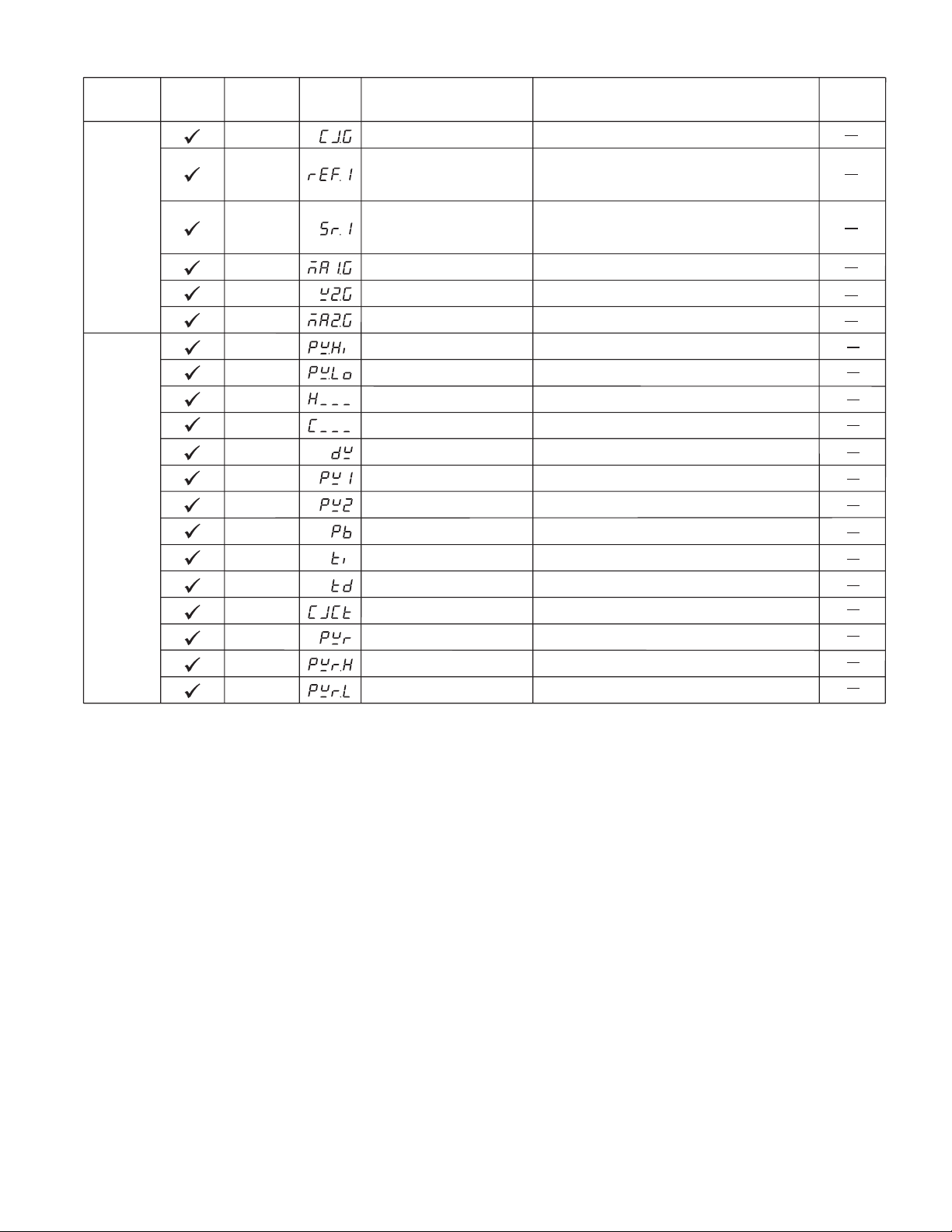
Table 1.4 Parameter Description ( continued 7/7 )Table 1.4 Parameter Description ( continued 7/7 )
Parameter
Contained
Contained
in
in
Basic
Basic
Function
Function
Parameter
Parameter
Notation
Notation
CJG
REF1
Display
Display
Format
Format
Cold Junction Gain
Calibration Coefficient
Reference Voltage 1
Calibration Coefficient for
RTD 1
Parameter
Description
Description
Low:
Low:
-199.9
-199.9
Range
High:
High:
199.9
199.9
Default
Default
Value
Value
Calibration
Mode
Menu
Display
Mode
Menu
SR1
MA1G
V2G
MA2G
PVHI
PVLO
MV1
MV2
DV
PV1
PV2
PB
TI
TD
CJCT
PVR
PVRH
PVRL
Serial Resistance 1
Calibration Coefficient for
RTD 1
mA Input 1 Gain Calibration
Coefficient
Voltage Input 2 Gain
Calibration Coefficient
mA Input 2 Gain Calibration
Coefficient
Historical Maximum Value of
PV
Historical Minimum Value of
PV
Current Output 1 Value
Current Output 2 Value
Current Deviation (PV-SV)
Value
IN1 Process Value
IN2 Process Value
Current Proportional Band
Value
Current Integral Time Value
Current Derivative Time
Value
Cold Junction Compensation
Temperature
Current Process Rate Value
Maximum Process Rate Value
Minimum Process Rate Value
Low:
Low:
Low:
Low:
Low:
Low:
Low:
Low:
Low:
Low:
Low:
Low:
Low:
Low:
Low:
Low:
Low:
Low:
-199.9
-199.9
-199.9
-199.9
-19999
-19999
0
0
-12600
-19999
-19999
0
0
0
-40.00 °C
-16383
-16383
-16383
High:
High:
High:
High:
High:
High:
High:
High:
High:
High:
High:
High:
High:
High:
High:
High:
High:
High:
199.9
199.9
199.9
199.9
45536
45536
100.00 %
100.00 %
12600
45536
45536
500.0 °C
(900.0 °F)
4000 sec
1440 sec
90.00 °C
16383
16383
16383
19

Input Type
Range Low
Range High
Input Type
Range Low
Range High
J_TC K_TC T_TC E_TC
-120 °C
(-184 °F)
1000 °C
(1832 °F)
N_TC
-250 °C
(-418 °F)
1300 °C
(2372 °F)
-200 °C
(-328 °F)
1370 °C
(2498 °F)
L_TC
-200 °C
(-328 °F)
900 °C
(1652 °F)
-250 °C
(-418 °F)
400 °C
(752 °F)
PT.DN PT.JS
-210 °C
(-346 °F)
(1292 °F)
-100 °C
(-148 °F)
900 °C
(1652 °F)
700 °C
(1112 °F)
-200 °C
(-328 °F)
600 °C
B_TC
0°C
(32 °F)
1820 °C
(3308 °F)
CT
0Amp
90 Amp
R_TC
0°C
(32 °F)
1767.8 °C
(3214 °F)
Linear ( V, mA)
or SPEC
1767.8 °C
(3214 °F)
-19999
45536
S_TC
0°C
(32 °F)
Table 1.5 Input ( IN1 or IN2 ) RangeTable 1.5 Input ( IN1 or IN2 ) Range
If A1FN =
Range of A1SP
same as range of
If A2FN =
Range of A2SP
same as range of
If PVMD =
Range of SP2
same as range of
Exception: If any of A1SP, A2SP or SP2 is configured with respect to
Exception: If any of A1SP, A2SP or SP2 is configured with respect to
CT input, its adjustment range is unlimited.
CT
PV1.H, PV1.L
IN1
PV1.H, PV1.L
IN1
PV1
IN1
input, its adjustment range is unlimited.
PV2.H,PV2.L
IN2
PV2.H,PV2.L
IN2
PV2
IN2 IN1, IN2
P1.2.H, P1.2.L
D1.2.H, D1.2.L
IN1, IN2
P1.2.H, P1.2.L
D1.2.H, D1.2.L
IN1, IN2
P1 2, P2 1
Table 1.6 Range Determination for A1SPTable 1.6 Range Determination for A1SP
Table 1.7 Range Determination for A2SPTable 1.7 Range Determination for A2SP
Table 1.8 Range Determination for SP2Table 1.8 Range Determination for SP2
20
Chapter 2 InstallationChapter 2 Installation
Dangerous voltages capable of causing death are sometimes present
Dangerous voltages capable of causing death are sometimes present
this instrument. Before installation or beginning any troubleshooting
in this instrument. Before installation or beginning any troubleshooting
in
procedures
procedures the power to all equipment must be switched off and isolated. Units
suspected
suspected of being faulty must be disconnected and removed to a properly
equipped
equipped workshop for testing and repair. Component replacement and internal
adjustments
adjustments must be made by a qualified maintenance person only.
instrument to rain or excessive moisture. This control is not to be used in hazardous
instrument
locations
locations as defined in Article 500 and 505 of the national electric code.
excessive shock, vibration, dirt, moisture, corrosive gases or oil. The ambient
excessive
temperature
temperature of the areas should not exceed the maximum rating specified in Chapter 8.
the power to all equipment must be switched off and isolated. Units
of being faulty must be disconnected and removed to a properly
workshop for testing and repair. Component replacement and internal
must be made by a qualified maintenance person only.
To minimize the possibility of fire or shock hazards, do not expose this
To minimize the possibility of fire or shock hazards, do not expose this
to rain or excessive moisture. This control is not to be used in hazardous
as defined in Article 500 and 505 of the national electric code.
Do not use this instrument in areas under hazardous conditions such as
Do not use this instrument in areas under hazardous conditions such as
shock, vibration, dirt, moisture, corrosive gases or oil. The ambient
of the areas should not exceed the maximum rating specified in Chapter 8.
2 1 Unpacking2 1 Unpacking
Upon receipt of the shipment remove the unit from the carton and inspect the
Upon receipt of the shipment remove the unit from the carton and inspect the
for shipping damage. If any damage due to transit , report and file a claim
unit for shipping damage. If any damage due to transit , report and file a claim
unit
the carrier. Write down the model number, serial number, and date code for
with
with the carrier. Write down the model number, serial number, and date code for
future
future reference when corresponding with our service center. The serial number
(S/N)
(S/N) and date code (D/C) are labeled on the box and the housing of control.
reference when corresponding with our service center. The serial number
and date code (D/C) are labeled on the box and the housing of control.
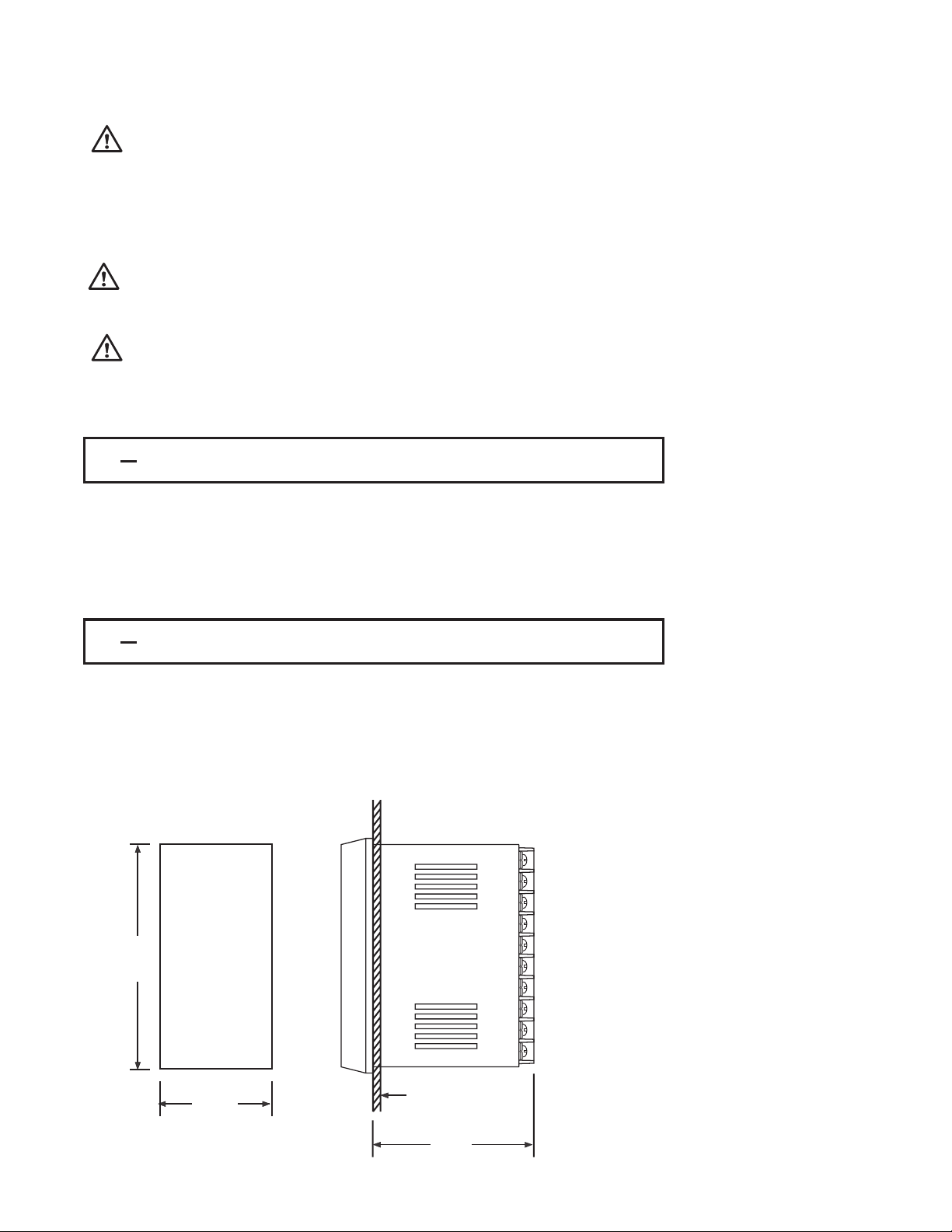
2 2 Mounting2 2 Mounting
Make panel cutout to dimension shown in Figure 2.1.Make panel cutout to dimension shown in Figure 2.1.
Set both mounting assembly options aside and insert the controller into panel
Set both mounting assembly options aside and insert the controller into panel
cutout. Install either the mounting clamp or screw set into provided grooves.
cutout.
Gently
Gently tighten the screws or slide the clamp till the controller’s front panel is
snug
snug against the front of the cutout.
Install either the mounting clamp or screw set into provided grooves.
tighten the screws or slide the clamp till the controller’s front panel is
against the front of the cutout.
Panel Cutout
92 mm
Figure 2.1 Mounting DimensionsFigure 2.1 Mounting Dimensions
45 mm
Panel
65 mm
21
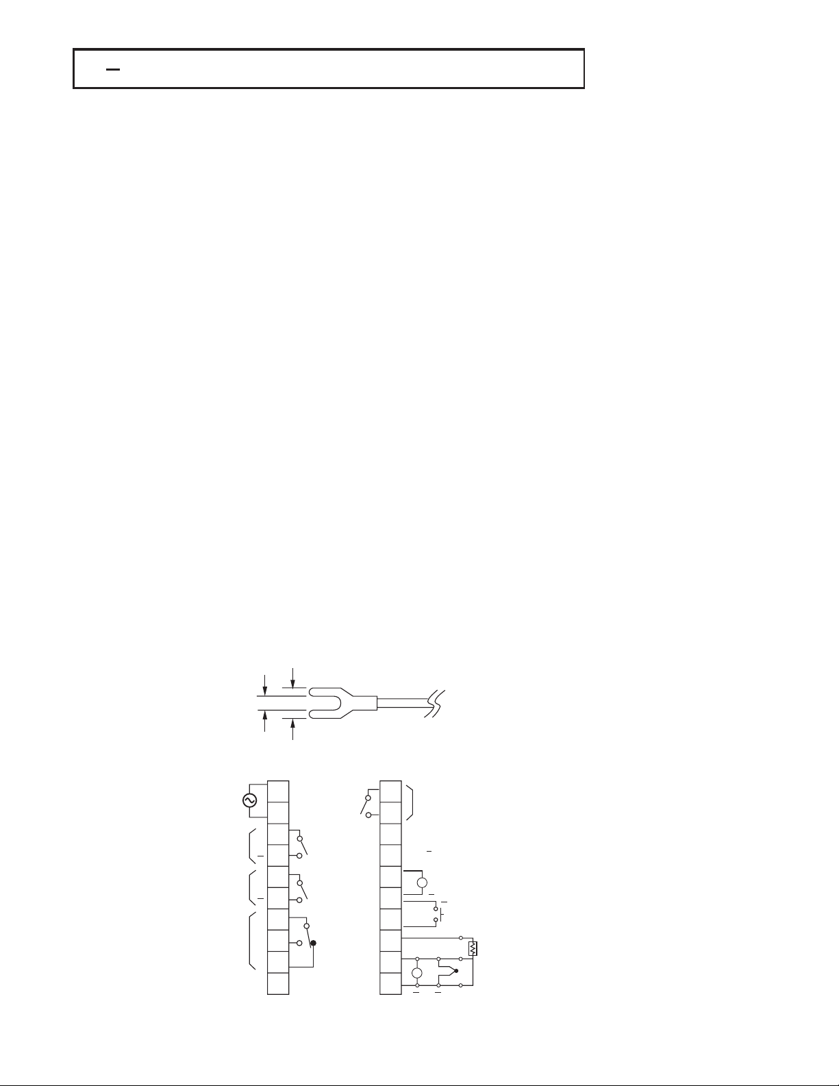
2 3 Wiring Precautions2 3 Wiring Precautions
Before wiring, verify the label for correct model number and options. Switch
*
off the power while checking.
Care must be taken to ensure that maximum voltage rating specified on the
*
label are not exceeded.
It is recommended that the power supplied to of these units is protected by
*
fuses or circuit breakers rated at the lowest value possible.
All units should be installed inside a suitably grounded metal enclosure to
*
prevent live parts being accessible from human hands and metal tools.
All wiring must conform to appropriate standards of good practice and local
*
codes and regulations. Wiring must be suitable for voltage, current, and
temperature rating of the system.
Use caution to avoid over-tightening the terminal screws.
*
Unused control terminals should not be used as jumper points as they may
*
be internally connected, causing damage to the unit.
Verify that the ratings of the output devices and the inputs as specified in
*
Chapter 8 are not exceeded.
Electric power in industrial environments contains a certain amount of noise in
*
the form of transient voltage and spikes. This electrical noise can enter and
adversely affect the operation of microprocessor-based controls. For this
reason we strongly recommend the use of shielded thermocouple extension
wire which connects the sensor to the controller. This wire is a twisted-pair
construction with foil wrap and drain wire. The drain wire is to be attached to
ground at one end only.
3.2mm min.
90-264 VAC
47-63 Hz
15 VA
OP1
OP2
Alarm 1
COM
7.0mm max.
1
2
+
3
4
+
5
6
7
8
9
10
L
N
NO
C
NO
C
NO
11
Alarm 2
12
AO+
13
TX1
AO
14
TX2
15
+
AI, CT
16
+ +
V
EI
+
A
RTD
B
B
C
17
18
NC
19
20
Figure 2.2 Lead TerminationFigure 2.2 Lead Termination
Figure 2.3 Rear Terminal
Figure 2.3 Rear Terminal
Connection Diagram
Connection
Diagram
22
ALL RELAY CONTACTS:
RESISTIVE 2A/240VAC
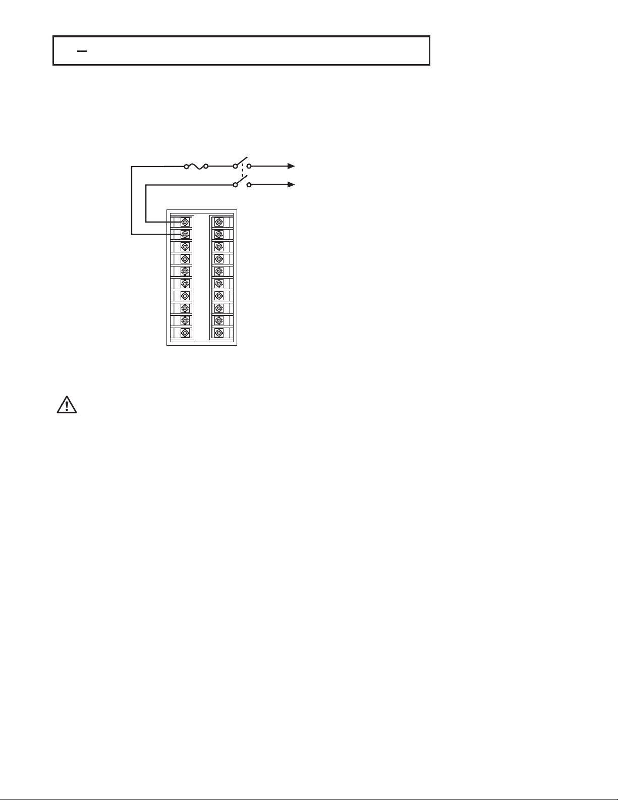
2 4 Power Wiring2 4 Power Wiring
The controller is supplied with one of the following, either 11-26 VAC / VDC or
The controller is supplied with one of the following, either 11-26 VAC / VDC or
90-264VAC. Check that the installation voltage corresponds with the power
90-264VAC.
rating
rating indicated on the product label before connecting power to the controller.
indicated on the product label before connecting power to the controller.
Check that the installation voltage corresponds with the power
Fuse
~
90 264 VAC or
11 26 VAC / VDC
~
11
1
12
2
13
3
14
4
15
5
16
6
17
7
18
8
19
9
20
10
Figure 2.4
Figure 2.4
Power Supply Connections
Power
Supply Connections
This equipment is designed for installation in an enclosure which provides
This equipment is designed for installation in an enclosure which provides
adequate protection against electric shock. The enclosure must be connected
adequate
earth ground.
to
to earth ground.
Local
Local requirements regarding electrical installation should be rigidly observed.
Precautions
Precautions should be taken to prevent unauthorized access to the power
terminals.
terminals.
protection against electric shock. The enclosure must be connected
requirements regarding electrical installation should be rigidly observed.
should be taken to prevent unauthorized access to the power
23

2 5 Sensor Installation Guidelines2 5 Sensor Installation Guidelines
Proper sensor installation can eliminate many problems in a control system. The
probe should be placed so that it can detect any temperature change with
minimal thermal lag. In a process that requires fairly constant heat output, the
probe should be placed closed to the heater. In a process where the heat
demand is variable, the probe should be closed to the work area. Some
experiments with probe location are often required to find this optimum position.
In a liquid process, addition of a stirrer will help to eliminate thermal lag. Since
the thermocouple is basically a point measuring device, placing more than one
thermocouple in parallel can provide an average temperature readout and
produce better results in most air heated processes.
Proper sensor type is also a very important factor to obtain precise
measurements. The sensor must have the correct temperature range to meet
the process requirements. In special processes the sensor might need to have
different requirements such as leak-proof, anti-vibration, antiseptic, etc.
Standard sensor limits of error are ±4 F (± 2 °C ) or 0.75% of sensed
temperature (half that for special ) plus drift caused by improper protection or an
over-temperature occurrence. This error is far greater than controller error and
cannot be corrected on the sensor except by proper selection and
replacement.
°
24
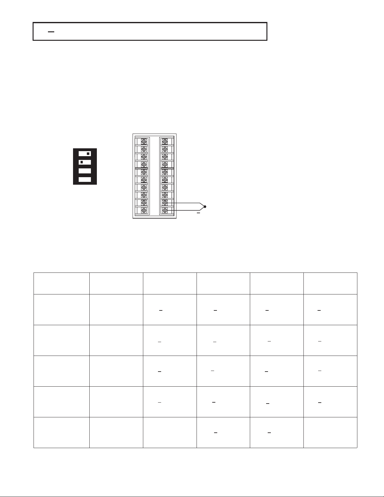
2 6 Thermocouple Input Wiring2 6 Thermocouple Input Wiring
Thermocouple input connections are shown in Figure 2.5. The correct type of
thermocouple extension lead-wire or compensating cable must be used for the entire
distance between the controller and the thermocouple, ensuring that the correct
polarity is observed throughout. Joints in the cable should be avoided, if possible.
If the length of thermocouple plus the extension wire is too long, it may affect the
temperature measurement. A 400 ohms K type or a 500 ohms J type thermocouple
lead resistance will produce 1 degree C temperature error approximately.
11
1
12
ON
1 2 3 4
DIP SwitchDIP Switch
2
13
3
14
4
15
5
16
6
17
7
18
8
19
9
20
10
+
Figure 2.5
Figure 2.5
Thermocouple Input Wiring
Thermocouple
Input Wiring
The colour codes used on the thermocouple extension leads are shown in Table 2.1.The colour codes used on the thermocouple extension leads are shown in Table 2.1.
Table 2.1 Thermocouple Cable Colour CodesTable 2.1 Thermocouple Cable Colour Codes
Thermocouple
Thermocouple
Ty pe
Ty pe
T
J
K
RSR
S
B
Cable
Cable
Material
Material
Copper(Cu)
Copper ( Cu )
Constantan
Constantan
Cu-Ni )
( Cu-Ni )
(
Iron(Fe)
Iron ( Fe )
Constantan
Constantan
Cu- Ni )
(Cu-Ni)
(
Nickel-Chromium
Nickel-Chromium
Ni-Cr )
( Ni-Cr )
(
Nickel-Aluminum
Nickel-Aluminum
Ni-Al )
(
( Ni-Al )
Pt-13%Rh,Pt
Pt-13%Rh,Pt
Pt-10%Rh,Pt
Pt-10%Rh,Pt
Pt-30%Rh
Pt-30%Rh
Pt-6%Rh
Pt-6%Rh
British
British
BS
BS
+ white
+ white
blue
blue
blue
* blue
*
+ yellow
+ yellow
blue
blue
black
* black
*
+ brown
+ brown
blue
blue
red
*red
*
+ white
+ white
blue
blue
green
* green
*
Use
Use
Copper Wire
Copper
Wire
American
American
ASTM
ASTM
+ blue
+ blue
red
red
blue
* blue
*
+ white
+ white
red
red
black
* black
*
+ yellow
+ yellow
red
red
yellow
* yellow
*
+ black
+ black
red
red
green
* green
*
+grey
+grey
red
red
grey
*grey
*
German
German
DIN
DIN
+red
+ red
brown
brown
brown
* brown
*
+red
+ red
blue
blue
blue
* blue
*
+red
+ red
green
green
green
* green
*
+red
+ red
white
white
white
* white
*
+red
+red
grey
grey
grey
*grey
*
French
French
NFE
NFE
+ yellow
+ yellow
blue
blue
blue
* blue
*
+ yellow
+ yellow
black
black
black
* black
*
+ yellow
+ yellow
purple
purple
yellow
* yellow
*
+ yellow
+ yellow
green
green
green
* green
*
Use
Use
Copper Wire
Copper
Wire
* Colour of overall sheath* Colour of overall sheath
25
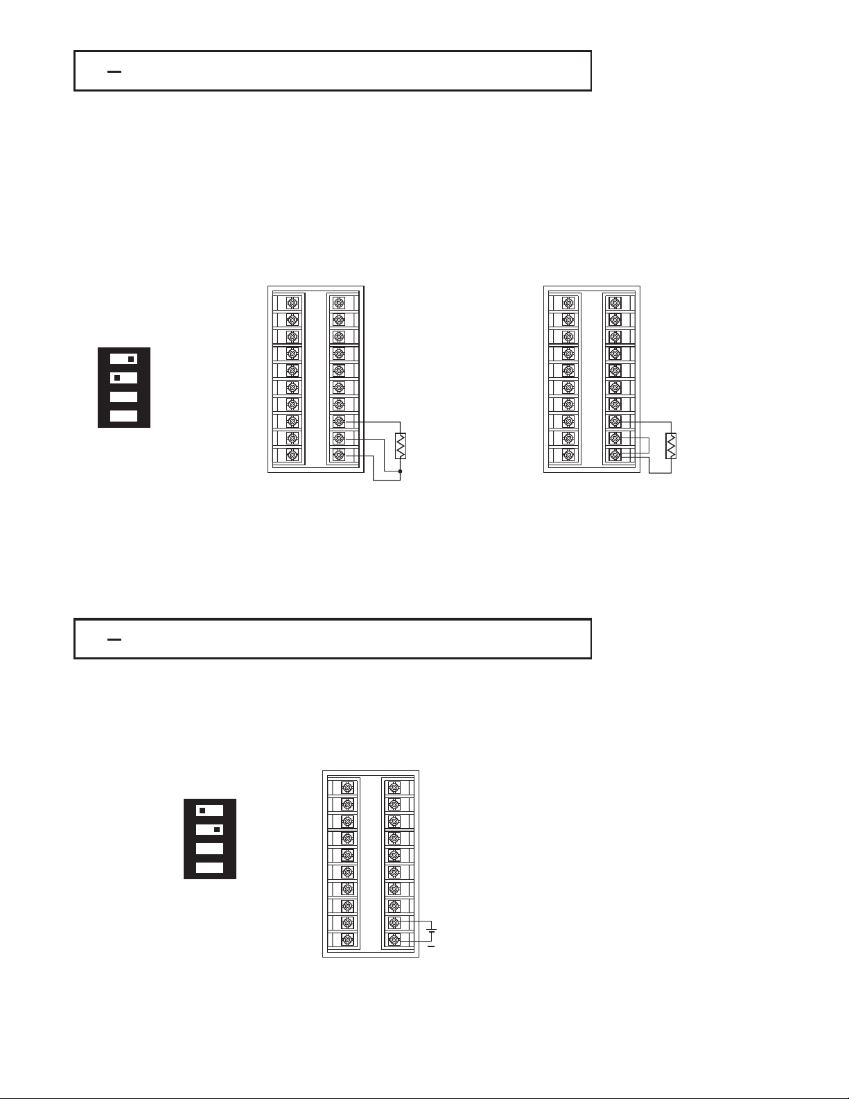
2 7 RTD Input Wiring2 7 RTD Input Wiring
RTD connections are shown in Figure 2.6, with the compensating lead connected to
RTD
connections are shown in Figure 2.6, with the compensating lead connected to
terminal
terminal 19. For two-wire RTD inputs, terminals 19 and 20 should be jumpered. The
three-wire
three-wire RTD offers the capability of lead resistance compensation provided that the
three
three leads should be of same gauge and equal length.
Two-wire RTDs should be avoided, if possible, for the purpose of accuracy. A 0.4
Two-wire RTDs should be avoided, if possible, for the purpose of accuracy. A 0.4
ohm lead resistance of a two-wire RTD will produce 1 degree C temperature
ohm lead resistance of a two-wire RTD will produce 1 degree C temperature
error.
error.
19. For two-wire RTD inputs, terminals 19 and 20 should be jumpered. The
RTD offers the capability of lead resistance compensation provided that the
leads should be of same gauge and equal length.
11
1
12
2
13
3
ON
1 2 3 4
DIP SwitchDIP Switch
Three-wire RTDThree-wire RTD
14
4
15
5
16
6
17
7
18
8
19
9
20
10
RTD
Two-wire RTDTwo-wire RTD
2 8 Linear DC Input Wiring2 8 Linear DC Input Wiring
DC linear voltage and linear current connections for input 1 are shown in Figure
DC linear voltage and linear current connections for input 1 are shown in Figure
and Figure 2.8 .
2.7 and Figure 2.8 .
2.7
11
1
12
2
13
3
Figure 2.6
14
4
15
5
16
6
17
7
18
8
19
9
20
10
Figure 2.6
Input Wiring
RTD Input Wiring
RTD
RTD
DC linear voltage and linear current connections for input 2 are shown in Figure
DC linear voltage and linear current connections for input 2 are shown in Figure
and Figure 2.10 .
2.9 and Figure 2.10 .
2.9
11
1
ON
1 2 3 4
DIP SwitchDIP Switch
12
2
13
3
14
4
15
5
16
6
17
7
18
8
19
9
20
10
+
0~1V, 0~5V
0~1V, 0~5V
1~5V, 0~10V
1~5V,
0~10V
Figure 2.7
Figure 2.7
Input 1 Linear Voltage Wiring
Input
26
1 Linear Voltage Wiring
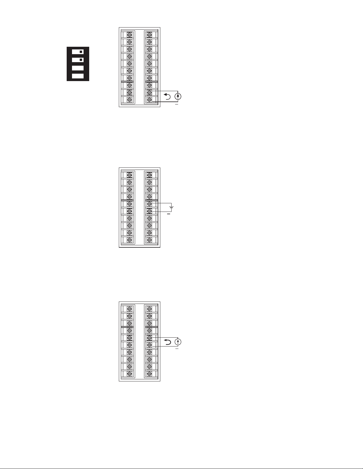
ON
1 2 3 4
DIP SwitchDIP Switch
11
1
12
2
13
3
14
4
15
5
16
6
17
7
18
8
19
9
20
10
11
1
12
2
13
3
14
4
15
5
16
6
17
7
18
8
19
9
20
10
+
0~20mA or
0~20mA or
4~20mA
4~20mA
+
0~1V, 0~5V
0~1V, 0~5V
1~5V, 0~10V
1~5V,
0~10V
Figure 2.8
Figure 2.8
1 Linear Current Wiring
Input 1 Linear Current Wiring
Input
Figure 2.9
Figure 2.9
2 Linear Voltage Wiring
Input 2 Linear Voltage Wiring
Input
11
1
12
2
13
3
14
4
15
5
16
6
17
7
18
8
19
9
20
10
+
0~20mA or
0~20mA or
4~20mA
4~20mA
Figure 2.10
Figure 2.10
2 Linear Current Wiring
Input 2 Linear Current Wiring
Input
27
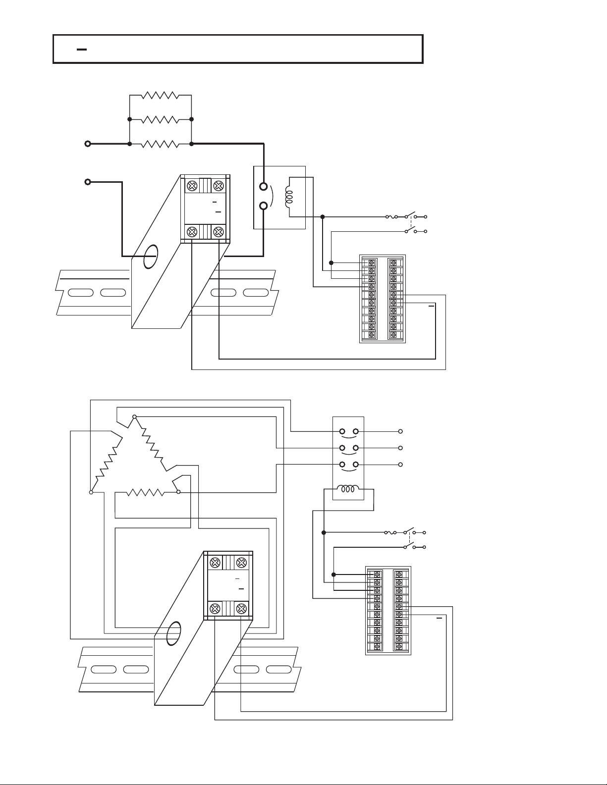
2 9 CT / Heater Current Input Wiring2 9 CT / Heater Current Input Wiring
Heater 1Heater 1
Heater 2Heater 2
Heater 3Heater 3
Heater SupplyHeater Supply
DIN RailDIN Rail
Current TransformerCurrent Transformer
CT94 1
+
1
2
Contactor
Contactor
Fuse
1
11
2
12
3
13
4
14
5
15
6
16
7
17
8
18
9
19
10
20
Mains
Mains
supply
supply
CT Signal Input
CT Signal Input
+
Figure 2.11
Figure 2.11
CT Input Wiring for
CT
Single
Single Phase Heater
Three Phase
Three Phase
Heater Power
Heater
Power
Input Wiring for
Phase Heater
Current TransformerCurrent Transformer
CT94 1
+
1
2
DIN RailDIN Rail
Make sure that the total current through CT94-1 not exceed 50A rms.Make sure that the total current through CT94-1 not exceed 50A rms.
28
Fuse
1
11
2
12
3
13
4
14
5
15
6
16
7
17
8
18
9
19
10
20
Mains
Mains
supply
supply
CT Signal Input
CT Signal Input
+
Figure 2.12
Figure 2.12
CT Input Wiring for
CT
Three
Three Phase Heater
Input Wiring for
Phase Heater
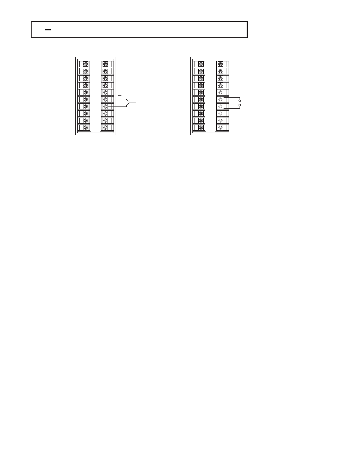
2 10 Event Input wiring2 10 Event Input wiring
11
1
12
2
13
3
14
4
15
5
16
6
17
7
18
8
19
9
20
10
Open Collector
Open Collector
Input
Input
The event input can accept a switch signal as well as an open collector signal. The
The event input can accept a switch signal as well as an open collector signal. The
input function ( EIFN ) is activated as the switch is closed or an open collector
event input function ( EIFN ) is activated as the switch is closed or an open collector
event
or a logic signal ) is pulled down.
(
( or a logic signal ) is pulled down.
refer to for event input function.Section 4-1
Also
Also refer to for event input function.Section 4-1
+
Switch InputSwitch Input
11
1
12
2
13
3
14
4
15
5
16
6
17
7
18
8
19
9
20
10
Figure 2.13
Figure 2.13
Event Input Wiring
Event
Input Wiring
29
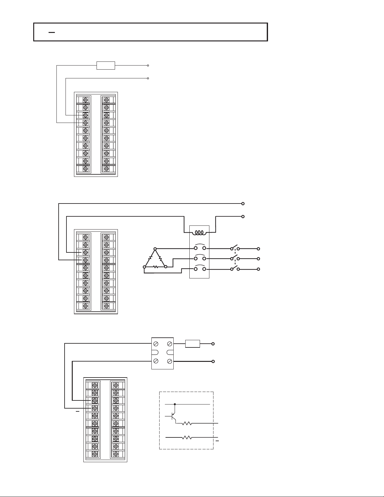
2 11 Output 1 Wiring2 11 Output 1 Wiring
Max. 2A
Max. 2A
Resistive
Resistive
Load
11
1
12
2
13
3
14
4
15
5
16
6
17
7
18
8
19
9
20
10
120V/240V
120V/240V
Supply
Mains Supply
Mains
Relay Output Direct DriveRelay Output Direct Drive
120V /240V
120V /240V
Supply
Mains Supply
Mains
Figure 2.14
Figure 2.14
Output 1 Wiring
Output
1 Wiring
30mA / 5V
30mA / 5V
Pulsed
Pulsed
Voltage
Voltage
11
1
12
2
13
3
14
4
15
5
16
6
17
7
18
8
19
9
20
10
Three Phase
Three Phase
Delta
Delta
Heater
Heater
Load
Load
Contactor
No Fuse
No Fuse
Breaker
Breaker
Three
Three
Phase
Phase
Heater
Heater
Power
Power
Relay or Triac (SSR)
Relay or Tria c (SSR)
Output to Drive
Output
Contactor
Contactor
to Drive
SSR
_
Load
120V /240V
120V /240V
Supply
Mains Supply
Mains
+
11
1
12
+
2
13
3
14
4
15
5
16
6
17
7
18
8
19
9
20
10
Internal CircuitInternal Circuit
5V
33
33
0V
+
3
Pulsed Voltage to Drive SSRPulsed Voltage to Drive SSR
4
30
 Loading...