

Ogden ETR-3000 Instruction Manual
PK486-OMC59
SOFTWARE VERSION
33.16 and HIGHER
Model ETR-3000
AUTOMATIC TUNING 1/32 DIN
®
SMARTER LOGIC Controller
S
S
L
L
L
M
M
O
O
O
A
A
R
R
G
G
G
T
T
I
E
E
C
I
I
R
R
C
C
®
INSTRUCTION MANUAL

Warning SymbolWarning Symbol
This Symbol calls attention to an operating procedure, practice, or the like, which, if not correctly performed or
adhered to, could result in personal injury, damage or destruction to part or all of the product and system. Do not
proceed beyond a warning symbol until the indicated conditions are fully understood and met.
Using the ManualUsing the Manual
Installer
System Designer
Expert User
Read Chapter 1, 2
Read All Chapters
Read Page 9
NOTE:
It is strongly recommended that a process incorporates an FM approved LIMIT CONTROL like the ETR-9040
It is strongly recommended that a process incorporates an FM approved LIMIT CONTROL like the ETR-9040
ETR-3 which will shut down the equipment at a preset process condition in order to preclude any possible
or ETR-3 which will shut down the equipment at a preset process condition in order to preclude any possible
or
damage
damage to individual components or system.
Information in this user's manual is subject to change without notice.
Copyright June, 2004, Ogden Manufacturing Co., all rights reserved. No part of this publication may be
reproduced, transmitted, transcribed or stored in a retrieval system. Similarly, this manual may not be translated into
any language in any form by any means without written permission Ogden Manufacturing Co.
to individual components or system.
©
2

Contents
Page No
Chapter 1 OverviewChapter 1 Overview
1-1 General Description ..................................................................................................................................................4
1-2 Ordering Code ..........................................................................................................................................................6
1-3 Programming Port ......................................................................................................................................................7
1-4 Keys and Displays .....................................................................................................................................................7
1-5 Menu Overview ..........................................................................................................................................................9
1-6 Parameter Descriptions ...........................................................................................................................................10
Chapter 2 Installation
Chapter 2 Installation
2-1 Unpacking ...............................................................................................................................................................13
2-2 Mounting .................................................................................................................................................................13
2-3 Wiring precautions ..................................................................................................................................................14
2-4 Power Wiring ...........................................................................................................................................................15
2-5 Sensor Installation Guidlines....................................................................................................................................15
2-6 Sensor Input Wiring .................................................................................................................................................15
2-7 Control Output Wiring ..............................................................................................................................................16
2-8 Alarm Wiring ............................................................................................................................................................17
2-9 Data Communication ..............................................................................................................................................18
Chapter 3 ProgrammingChapter 3 Programming
3-1 Lockout ....................................................................................................................................................................19
3-2 Signal Input...............................................................................................................................................................19
3-3 Control Outputs .......................................................................................................................................................20
3-4 Alarm ........................................................................................................................................................................22
3-5 Display Configuration ...............................................................................................................................................23
3-6 Ramp .......................................................................................................................................................................23
3-7 Dwell Timer ..............................................................................................................................................................24
3-8 PV Shift .....................................................................................................................................................................24
3-9 Digital Filter ..............................................................................................................................................................25
3-10 Failure Transfer ........................................................................................................................................................25
3-11 Auto-tuning ..............................................................................................................................................................26
3-12 Manual tuning ..........................................................................................................................................................27
3-13 Manual Control ........................................................................................................................................................28
3-14 Data communication ...............................................................................................................................................28
Chapter 4 ApplicationsChapter 4 Applications
4-1 Heat Only Control with Dwell Timer .........................................................................................................................29
4-2 Cool Only Control ....................................................................................................................................................30
4-3 Heat-Cool Control ....................................................................................................................................................31
Chapter 5 Calibration ...................................................................................................................................32Chapter 5 Calibration
Chapter 6 Specifications..............................................................................................................................35Chapter 6 Specifications
Appendix
A-1 Error Codes .............................................................................................................................................................39
A-2 Warranty....................................................................................................................................................................39
3
Chapter 1 OverviewChapter 1 Overview
1-1 General Description1-1 General Description
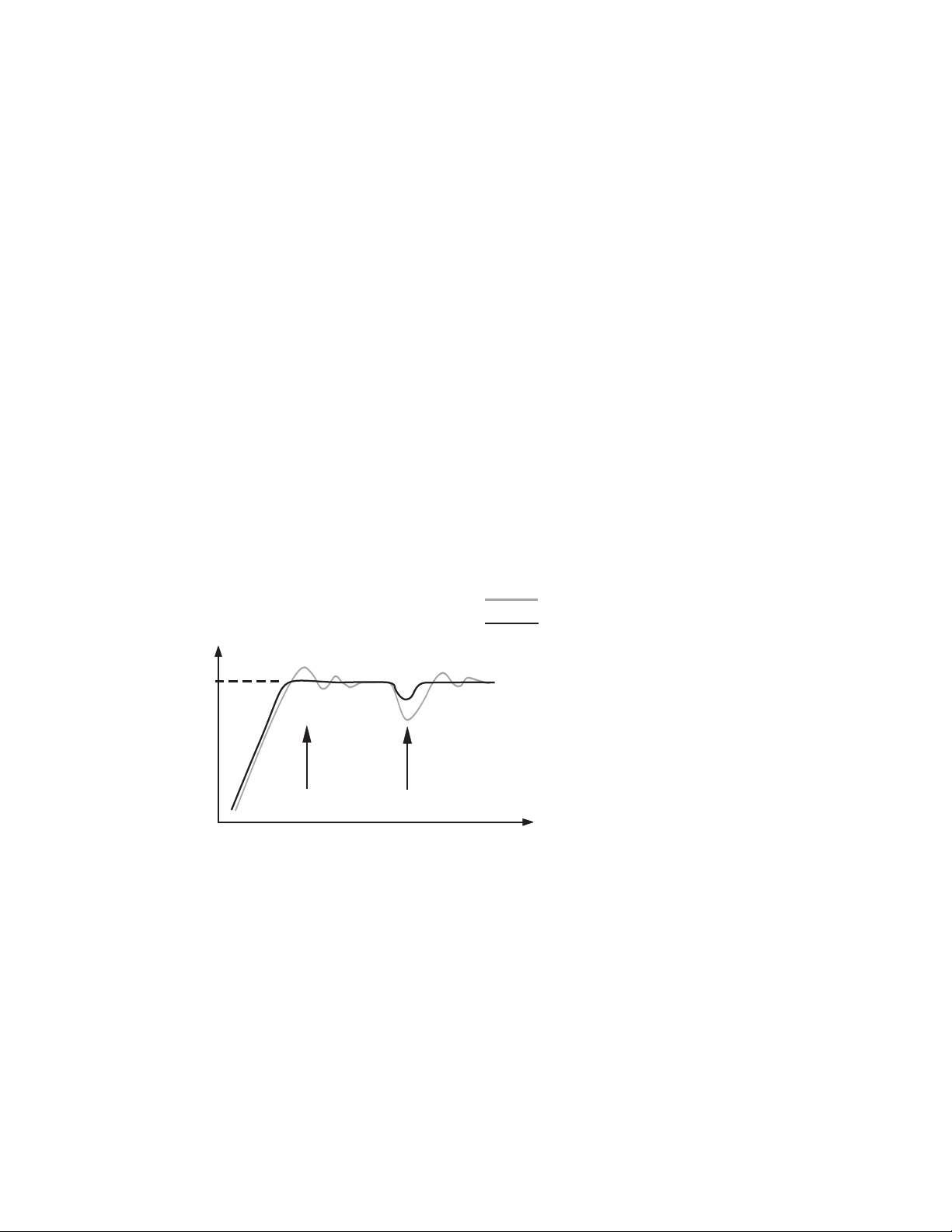
The ETR-3000 Smarter Logic PID microprocessor-based controller incorporates a bright, easy to read 4-digit LED
display. The front LED display can be programmed to indicate either the process value or set point value. Smarter
Logic technology enables a process to reach a predetermined set point in the shortest possible time, with minimum
overshoot during power-up or external load disturbance.
The ETR-3000 is a 1/32 DIN size panel mount controller. These units are powered by an 11-26 or 90-250 VDC/VAC
supply, incorporatinga2ampcontroloutput relay as standard. The second output can be used as cooling control,
an alarm or dwell timer. Prior to shipment, both outputs can be independently configured as triac, 5V logic output,
linear current or linear voltage to drive an external device.
plus a dwell timer that can be configured for the second output.
and thermocouple types J, K, T, E, B, R, S, N, L without need to physically modify the unit. The input signal is
digitized by using a 18-bit A to D converter. A fast sampling rate allows the ETR-3000 unit to control fast processes.
Digital communications RS-485 or RS-232 are available as an additional option. This option allows the units to be
integrated with a supervisory control system and/or software.
A programming port is available for automatic configuration, calibration and testing without the need to access the
keys on front panel.
By using proprietary Fuzzy modified PID technology(Smarter Logic), the control loop will minimize overshoot and
undershoot in the shortest time possible. The following diagram is a comparison of results with and without Fuzzy
technology.
There are six independent programmable alarm modes
The units are fully programmable for RTD (PT100)
PID control when properly tuned
Temperature
Set
point
PID + Fuzzy control
Warm Up
Load Disturbance
Time
Figure 1.1
Figure 1.1
Fuzzy Control Advantage
Fuzzy
Control Advantage
High AccuracyHigh Accuracy
The ETR-3000 is manufactured with custom designed ASIC(Application Specific Integrated Circuit ) technology which
contains an 18-bit A to D converter for high resolution measurement ( true 0.1 °F resolution for thermocouple and standard
Pt100 RTD’s ) and a 15-bit D to A converter for linear current or voltage control output. The ASIC technology provides
improved operating performance, low cost, enhanced reliability and higher density internal storage.
4

Fast Sampling RateFast Sampling Rate
The sampling rate of the input A to D converter reaches 5 times/second. This fast sampling rate allows this series to
control fast processes.
Smarter Logic ControlSmarter Logic Control
The function of Smarter Logic control is to automatically adjust the PID parameters from time to time. These dynamic
adjustments are made in order to tune the output value to be more flexible and adaptive to various processes. The
result is to enable a process to reach a predetermined set point in the shortest possible time with minimum overshoot
and/or undershoot during power-up or external load disturbance.
Digital CommunicationsDigital Communications
The ETR-3000 can be equipped with an RS-485 or RS-232 interface card to provide digital communications. By
using shielded twisted pair wire, at most 247 units can be connected together via an RS-485 interface to a host
computer. An industry standard Modbus RTU is used for the communication protocol.
Programming PortProgramming Port
A programming port is used to connect the unit to a hand-held programmer or a PC for quick configuration.
Additionally, it can be connected to an Automatic Test Equipment (ATE) system for automatic testing & calibration.
Auto-tune
The auto-tune function allows the user to simplify the initial setup for a new system. A clever algorithm is provided to
obtain an optimal set of control parameters for the process. The Auto-tune feature can be applied either as the
process is warming up ( cold start ) or as the process is in a steady state ( warm start ).
Lockout ProtectionLockout Protection
In order to meet various security requirements, one of four lockout levels can be selected to prevent the unit from
being changed without authorization.
Bumpless TransferBumpless Transfer
The Bumpless Transfer feature is a unique process protection feature that is employed upon a sensor break condition
or input problem. Bumpless transfer allows a controller to continue to proportion it’s output based on previous
process and control characteristics. Hence, the process can be temporarily controlled just as if running a closed
loop control application, making the severe problem of a Thermocouple error temporarily invisible. Bumpless transfer
is not to be used for an extended period time as in open loop control, run-away may occur.
Soft-start RampSoft-start Ramp
The ramping function is performed during power up as well as any time the set point is changed. It ramp will control
both ramp up and/or ramp down. The process value will reach the set point with a predetermined constant rate.
Digital FilterDigital Filter
A first order low pass filter with a programmable time constant is used to improve the stability of process value. This
is particularly useful in certain applications where the process value is too unstable to be read.
5

1-2 Ordering Code1-2 Ordering Code
ETR-3000-
Power InputPower Input
4: 90 - 250 VAC, 50/60 HZ
4: 90 - 250 VAC, 50/60 HZ
11 - 26 VAC or VDC
5: 11 - 26 VAC or VDC
5:
Signal InputSignal Input
1: Standard Input
1: Standard Input
Thermocouple:J, K,
Thermocouple:J,
T,
T, E, B, R, S, N, L
RTD:
RTD: PT100 DIN,
Pt100
Pt100 JIS
Linear voltage or
4:
4: Linear voltage or
current
current such as
4-20mA
4-20mA (specify range)
E, B, R, S, N, L
K,
PT100 DIN,
JIS
such as
(specify range)
Output 1Output 1
0: None
0: None
Relay rated
1: Relay rated
1:
2A/240VAC
2A/240VAC
SSR Drive, 5V/30mA
2:
2: SSR Drive, 5V/30mA
Isolated 4 - 20mA / 0 - 20mA
3:
3: Isolated4-20mA/0-20mA
Isolated 1 - 5V / 0 - 5V
4:
4: Isolated1-5V/0-5V
Isolated 0 - 10V
5:
5: Isolated0-10V
Triac output 1A / 240VAC,SSR
6:
6: Triac output 1A / 240VAC,SSR
SSR Drive,14V/30mA
C:
C: SSR Drive,14V/30mA
Output 2Output 2
0: None
0: None
1: Form A relay 2A/240VAC
1:
2:
2: Pulsed voltage to
3:
3: Isolated4-20mA/0-20mA
4:
4: Isolated1-5V/0-5V
5:
5: Isolated0-10V
6:
6: Triac output, 1A / 240VAC, SSR
7:
7: Isolated 20V/25mA transducer power
8:
8: Isolated 12V/40mA transducer power
9:
9: Isolated 5V/80mA transducer power
C:
C: Pulsed voltage to drive SSR,14V/30mA
Communications
0: None
0: None
RS-485 interface
1: RS-485 interface
1:
RS-232 interface
2:
2: RS-232 interface
Retransmit
3:
3: Retransmit
4:
4: Retransmit 1-5V /0-5V
5:
5: Retransmit 0-10V
mA / 0-20 mA
4-20
4-20 mA / 0-20 mA
Retransmit 1-5V /0-5V
Retransmit 0-10V
Display Color:Display Color:
0: Red
0: Red
(Standard)
(Standard)
Green
1: Green
1:
(Special
Form A relay 2A/240VAC
Pulsed voltage to
SSR, 5V / 30mA
drive
drive SSR, 5V / 30mA
Isolated 4 - 20mA / 0 - 20mA
Isolated 1 - 5V / 0 - 5V
Isolated 0 - 10V
Triac output, 1A / 240VAC, SSR
Isolated 20V/25mA transducer power
supply
supply
Isolated 12V/40mA transducer power
supply
supply
Isolated 5V/80mA transducer power
supply
supply
Pulsed voltage to drive SSR,14V/30mA
(Special Order)
Order)
Related ProductsRelated Products
SNA10A = Smart Network Adaptor for third party
SNA10A = Smart Network Adaptor for third party
software, which converts 255 channels of
software,
RS-485 or RS-422 to RS-232 Network.
RS-485 or RS-422 to RS-232 Network.
SNA10B = Smart Network Adaptor for ETR-Net
SNA10B = Smart Network Adaptor for ETR-Net
software, which converts 255 channels of
software, which converts 255 channels of
RS-485 or RS-422 to RS-232 network.
RS-485 or RS-422 to RS-232 network.
SNA12A = Smart Network Adaptor for programming
SNA12A = Smart Network Adaptor for programming
port to RS-232 interface
port to RS-232 interface
ETR-Set = Configuration Software
ETR-Set = Configuration Software
CC94-1 = RS-232 Interface Cable ( 2M )
CC94-1
CETR-9000-1 = Programming port cable for ETR-3000
CETR-9000-1
= RS-232 Interface Cable ( 2M )
= Programming port cable for ETR-3000
which converts 255 channels of
6

1-3 Programming Port1-3 Programming Port
1
3
5
Rear
Terminal
Front
Panel
Access Hole
2
46
ETR-3000
Figure 1.2 Programming Port OverviewFigure 1.2 Programming Port Overview
A special connector can be used to connect to the programming port which is then connected to a PC for automatic
configuration. It can also can be connected to an ATE system for automatic calibration and testing.
The programming port is used for off-line automatic setup and testing procedures only. Don't attempt to make any
connection to these pins while the unit is powered up and being used for normal control purposes.
1- 4 Keys and Displays1- 4 Keys and Displays
KEYPAD OPERATIONKEYPAD OPERATION
SCROLL KEY :
SCROLL KEY :
This key is used to select a parameter to be viewed or adjusted.
UP KEY :
UP
KEY :
This key is used to increase the value of a selected parameter.
DOWN KEY :
DOWN
This key is used to decrease the value of a selected parameter.
RESET KEY :
RESET
This key is used to:
1. Revert the controllers display back to the process value (or set point value if DISP is set to SP1).
2. Reset the latching alarm, once the alarm condition is removed.
3. Stop the manual control mode, auto-tuning mode and calibration mode.
4. Clear the message of a communications error or auto-tuning error.
5. Restart the dwell timer when the dwell timer has timed out.
6. Enter the manual control menu when a failure condition occurs.
ENTER KEY :
ENTER
Press for 3 seconds to:
1. Enter the setup menu. The display will show .
2. Enter the manual control mode when the manual control menu, or is displayed.
3. Enter the controller into auto-tuning mode. During auto-tuning mode is displayed.
4. Perform calibration to a selected parameter during the calibration procedure. Press for 5 seconds to select
KEY :
KEY :
Press for 3 seconds or longer .
KEY :
calibration mode.
7
Output 2
Output 2
Indicator
Indicator
Output 1
Output 1
Indicator
Indicator
O1
O2
Figure 1.3 Front Panel DescriptionFigure 1.3 Front Panel Description
ETR-3000
3 Silicone Rubber Buttons
3 Silicone Rubber Buttons
for ease of control setup
for
ease of control setup
and set point adjustment.
and
set point adjustment.
Table 1.1 Character LegendTable 1.1 Character Legend
A
B
C
c
Dh
E
F
G
H
I
J
K
L
M
C
N
O
P
Q
R
: Characters Displayed by a Symbol: Characters Displayed by a Symbol
S
T
U
V
W
X
Y
Z
?
=
Displays the program code of the product for 2.5 seconds.
O1
O2
ETR-3000
8
C
The ETR-3000 goes through an initial Power up self test in which
it displays the Program code and version of the controller. The
left diagram shows program no. 34 for an ETR-3000, version 16.
Figure 1.4
Figure 1.4
Display at Power-up
Display
at Power-up
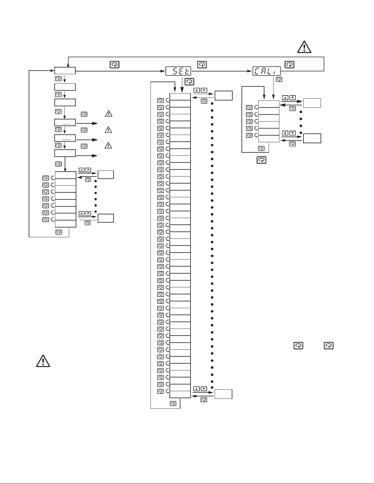
1- 5 Menu Overview1- 5 Menu Overview
User menu *1User menu *1
PV
SP1
SP2
H
C
A-T
INPT
UNIT
DP
PB
TI
TD
CYC1
ADDR
3 sec.
3 sec.
3 sec.
Manual
Manual
Mode
Mode
Manual
Manual
Mode
Mode
Auto-tuning
Auto-tuning
Mode
Mode
Value
Value
3 sec.
Applying these modes will
break the control loop
and change some of the
previous setting data. Make
sure that the system will
tolerate these modes.
Setup menu*1Setup menu*1
LOCK
INPT
UNIT
DP
INLO
INHI
SP1L
SP1H
SHIF
FILT
DISP
PB
TI
TD
OUT1
O1TY
O1FT
O1HY
CYC1
OFST
RAMP
RR
OUT2
O2TY
O2FT
O2HY
CYC2
CPB
DB
ALMD
COMM
ADDR
BAUD
DATA
PARI
STOP
SEL1
SEL2
SEL3
SEL4
SEL5
SEL6
SEL7
SEL8
RELO
REHI
4 sec.
Value
Value
Calibration ModeCalibration Mode
2 sec.
*2
ADLO
ADHI
RTDL
RTDH
CJLO
CJHI
Press for
3 seconds to
perform calibration.
The flow chart shows a
*1:
complete listing of all
parameters. Not every
parameter will be displayed.
Depending on controller
set-up, some parameters
may not be displayed.
Release , press
*2:
again for 2 seconds or
longer (but not longer
than 3 seconds), then
release to enter the
calibration menu.
5 sec.
Value
Value
9
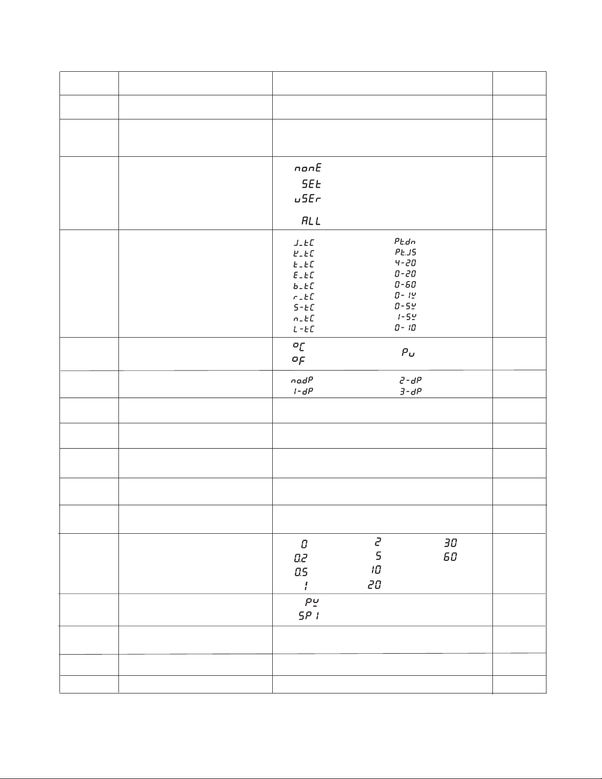
1-6 Parameter Descriptions1-6 Parameter Descriptions
Parameter
Notation
SP1
SP2
LOCK
INPT
UNIT
Parameter Description
Set point for output 1
Set point for output 2 when
output 2 performs alarm
function or dwell timer
Select parameters to be locked
Input sensor selection
Input unit selection
Range
Low: SP1L High :SP1H
Low: -19999 High :45536
0 : No parameters are locked
1 : Setup data is locked
2 : Setup and User data is locked
Set point is un- locked
3 : All data is locked
0
1
2
3
4
5
6
7
8
: Degree C unit
0
: Degree F unit
1
J type T/C
:
K type T/C
:
T type T/C
:
E type T/C
:
B type T/C
:
R type T/C
:
S type T/C
:
N typeT/C
:
L type T/C
:
9
10
11
12
13
14
15
16
17
2
:
PT 100 ohms DIN
:
PT 100 ohms JIS
4-20mA
:
0-20mA
:
0-60mV
:
0-1V
:
0-5V
:
1-5V
:
0 - 10V
:
: Process unit
Default
Value
77.0 °
()
()
25.0 °C
18.0°
10.0 °C
F
F
0
1
(0)
0
(1)
DP
INLO
INHI
SP1L
SP1H
SHIF
FILT
DISP
PB
Decimal point selection
Input low scale value
Input high scale value
Low limit of set point
value
High limit of set point
value
PV shift (offset) value
Filter damping time
constant of PV
(seconds)
Normal display selection
Proportional band value
0
1
Low:
Low:
Low:
Low:
Low:
0
: No decimal point
: 1 decimal digit
-19999
INLO+50
-19999
SP1L
-360.0 °C
(-200.0 )
:0
1 : 0.2
2
3
: 0.5
:1
0
1
Low: 0
: 2 decimal digits
: 3 decimal digits
45486
45536
45536
45536
360.0 °F
( 200.0 °C)
8
9
°C
2
3
High:
High:
High:
High:
High:
4
5
6
7
:2
:5
:10
:20
: Display process value
: Display set point 1 value
High:
932.0 °F
(500.0 °C)
:30
:60
1
0°
F
()
-17.8 °C
200.0°
93.3 °C
0°
F
F
F
()
()
-17.8 °C
1000°
()
537.8 °C
0.0
2
0
18.0
°F
()
10.0 °C
10
TI
TD
Integral time value
Derivative time value
Low: 0
Low: 0
High:
High:
1000 sec
360.0 sec
100
25.0

Parameter
Notation
Parameter Description
Range
Default
Value
OUT1
O1TY
O1FT
O1HY
CYC1
Output 1 function
Output 1 signal type
Output 1 failure transfer
mode
Output 1 ON-OFF control
hysteresis
Output1cycletime
OFST Offset value for P control
RAMP
RR
OUT2
O2TY
Ramp function selection
Ramp rate
Output 2 function
Output 2 signal type
0
1
0
1
2
3
4
: Reverse (heating ) control
: Direct (cooling) control
: Relay
: Solid state relay drive
: Solid state relay
:4-20mA
: 0-20mA
5
6
7
8
: 0-1V
: 0-5V
: 1-5V
: 0 - 10V
Select BPLS ( bumpless transfer ) or 0.0 ~
100.0 % to continue output 1 control function
as the unit fails, or select OFF (0) or ON (1) for
ON-OFF control.
Low: 0.1 High: 90.0° ( )F 50.0°C
Low: 0.1 High: 90.0 sec.
Low: 0
0 : No Function
1 : Use unit/minute
Low: 0
0 : Output 2 No Function
1 : Dwell timer action
2 : Deviation High Alarm
3 : Deviation Low Alarm
4 : Deviation out of band Alarm
0
1
2
3
4
: Relay output
: Solid state relay drive
: Solid state relay
:4-20mA
:0-20mA
High: 100.0 %
2 : Use unit/hour
High:
900.0 °F
(500.0 °C)
5 : Deviation in band Alarm
6 : Process High Alarm
7 : Process Low Alarm
8 : Cooling PID Function
5
6
7
8
:0-1V
:0-5V
:1-5V
:0-10V
0
0
0
0.2 °F
()0.1 °C
18.0
25.0
0
0.0
2
0
O2FT
O2HY
CYC2
CPB
DB
ALMD
Output 2 failure transfer
mode
Output 2 hysteresis value
when output 2 performs
alarm function
Output2cycletime
Cooling proportional band
value
Heating-cooling dead
band
(negative value = overlap)
Alarm operation mode
Select BPLS ( bumpless transfer ) or 0.0 ~ 100.0 %
to continue output 2 control function as the unit
fails, or select ON (0) or OFF (1) for alarm and dwell
timer function.
Low: 0.1
Low: 0.1
Low: 50
Low: -36.0
0
1
High:
High: 90.0 sec.
High: 300 %
High: 36.0 %
: Normal alarm action
: Latching alarm action
90.0 °F
(50.0 °C)
2
3
: Hold alarm action
: Latching & actionHold
0
0.2 °F
(0.1 °C)
18.0
100
0
0
11
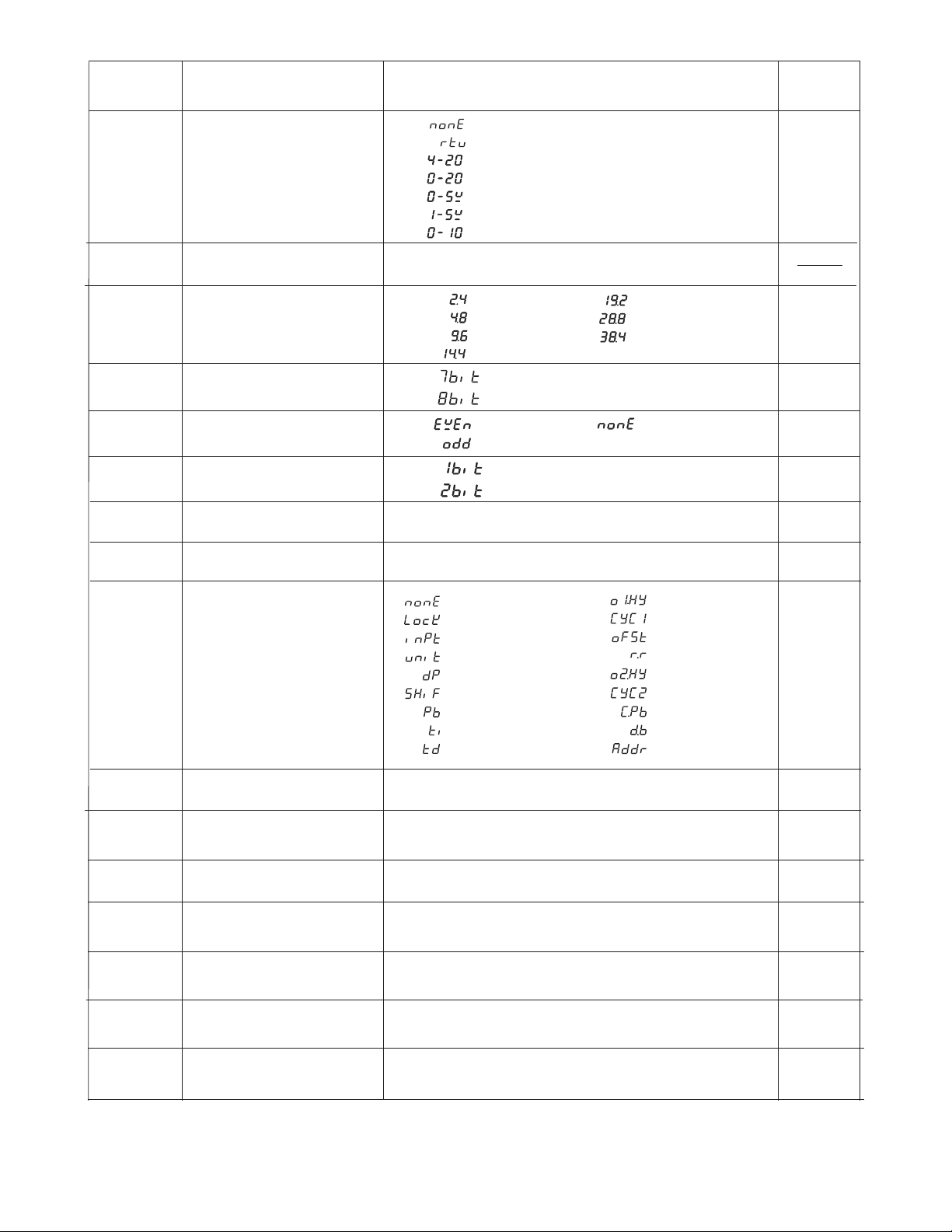
Parameter
Notation
Parameter Description
COMM Communication function
ADDR
BAUD
DATA
PARI
STOP
RELO
Address assignment of
digital communication
Baud rate of digital
communication
Data bit count of digital
communication
Parity bit of digital
communication
Stop bit count of digital
communication
Retransmission low scale
value
Range
0 : No communication
1 : Modbus RTU mode protocol
2
3
4
5
6
:4-20mA retransmission output
:0-20mA retransmission output
:0-5V retransmission output
:1-5V retransmission output
:0-10V retransmission output
Low: 1 High: 255
0
1
2
3
: 2.4 Kbits/s
: 4.8 Kbits/s
: 9.6 Kbits/s
: 14.4 Kbits/s
4
5
6
0 : 7 data bits
1 : 8 data bits
0 : Even parity
1 : Odd parity
2 : No parity bit
0 : One stop bit
1 : Two stop bits
Low: -19999
High: 45536
: 19.2 Kbits/s
: 28.8 Kbits/s
: 38.4 Kbits/s
Default
Value
1
2
1
0
0
32.0 °F
(0.0 °C)
REHI
SEL1
SEL2
SEL3
SEL4
SEL5
SEL6
Retransmission high scale
value
Select 1'st parameter for
user menu
Select 2'nd parameter for
user menu
Select 3'rd parameter for
user menu
Select 4'th parameter for
user menu
Select 5'th parameter for
user menu
Select 6'th parameter for
user menu
Low: -19999
0
1
2
3
4
5
6
7
8
: No parameter selected
: LOCK is put ahead
: INPT is put ahead
: UNIT is put ahead
: DP is put ahead
: SHIF is put ahead
: PB is put ahead
: TI is put ahead
: TD is put ahead
Same as SEL1
Same as SEL1
Same as SEL1
Same as SEL1
Same as SEL1
High: 45536
10
11
12
13
14
15
16
17
212.0 °F
()100.0 °C
9
: O1HY is put ahead
: CYC1 is put ahead
: OFST is put ahead
: RR is put ahead
: O2HY is put ahead
: CYC2 is put ahead
: CPB is put ahead
: DB is put ahead
: ADDR is put ahead
2
3
4
6
7
8
12
SEL7
SEL8
Select 7'th parameter for
user menu
Select 8'th parameter for
user menu
Same as SEL1
Same as SEL1
10
17
 Loading...