

Ogden ETR-3 Instruction Manual

MANUAL NO. 33
ETR-3 FM SUB-PANEL MOUNT
HI-LIMIT CONTROL
INSTRUCTION
MANUAL
The ETR-3 Series is designed for industrial and commercial applications which require high temperature
protection. These controls feature a latching, manually
resettable relay output which de-energizes whenever
the sensed temperature exceeds the set point temperature. It can also be configured as an on-off temperature
control.
SPECIFICATIONS
Power Input:
120VAC ±15%, 50/60Hz, 3VA max.
standard (240VAC and other AC/DC voltages
optional).
Control Output: SPDT Relay rated 3.8 (1.5) Amps
Res. and 1.5 (.8) Amps Pilot Duty 120 (240)VAC.
100,000 cycles. Optional DC output to drive SSR.
Control Mode: Latching with Manual Reset or power off.
Reset Function: Integral reset switch standard;
terminals available for optional remote reset switch.
Set Point Adjustment: Local SP dial adjustment.
Compensation (TC only): Automatic cold junction
compensation.
Control Stability: Typically less than ±5µV/°F ambient
and 0.1% of SPAN/% rated line voltage.
Set Point Accuracy: ±3% of FS maximum at 78°F
(25°C) and rated line voltage.
Sensor Break Protection:
Contacts 4 and 5 open for thermocouple or RTD
break.
Ambient Operating Temperature:
32 - 140°F (0 - 60°C).
MECHANICAL
Enclosure Material: Noryl, Black color.
Field Terminations: Screw Terminals with wire
clamping plates and touch safe shield.
Mounting: 35mm DIN rail or surface mounting.
AGENCY APPROVALS: UL 873 and CUL per CSA
C22.2 No.24 File #E179225; FM 3545.
Switc
t
DIMENSIONS:
MOUNTING
The ETR-3 can be surface mounted or mounted on a DIN
rail. The ETR-3 must be located inside a suitable control
enclosure. It can be mounted to any suitable flat surface
using two #8 screws (not supplied). To install simply
position the top set of rear clips over the top of the DIN
rail. Then swing the bottom of the controller toward the
rail applying pressure until the lower clips snap on to the
bottom of the DIN rail. To remove apply pressure to the
top of the controller’s base and move the bottom of the
controller toward you. Then lift the top pf the controller
off the upper DIN rail.
3-5/16"
(84mm)
3/8"
(9.5mm)
Limit Controller
234
1
N.C.
L2
N.O.
Relay
Output
L1
AC
+ –
DC
Power
Input
2-1/2"
(63.5mm)
200
150
°F
RESET
56789
+ –
COM
TC or
RTD
Sensor
350
300
Optional N.O.
Remote Reset
2-9/16"
(65mm)
3"
(76.2mm)
Integral Rese
Button
h
Set point
adjust
2-1/2"
(63.5mm)
Panel mounting foot
with clearance holes
for #8 screw
(2 places)
35mm
DIN rail
mounting clips
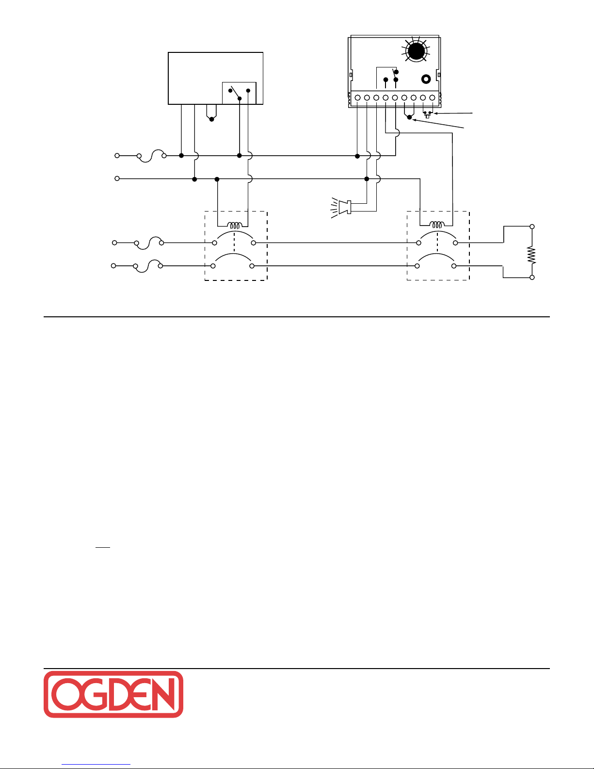
WIRING
Carefully follow the terminal diagram pictured on the controller’s housing and shown above. The power and load
wiring should be 18 AWG or larger size. Be sure to observe
that the ratings for voltage and current are not exceeded. All
local and national electrical codes must be followed. Use only
the sensor type as indicated on the control and maintain correct polarity. THE RED THERMOCOUPLE LEAD ALWAYS
CONNECTS TO THE NEGATIVE (–) TERMINAL.
To reduce electrical noise, the thermocouple wire must be isolated from any power or heater wiring. Shielded thermocouple wire may be necessary in high noise environments or
when lead lengths exceed 10 feet. Thermocouples are tip
sensitive and must be in good mechanical contact with the
load.
OPERATION
The set point temperature is adjustable by turning the integral
dial. If the set point is exceeded, contacts 4 and 5 will open.
It will remain in this state until the temperature drops below
the set point and
the controller is manually reset. Manual
reset can be accomplished by one of the following means: a)
Press the “reset button”. b) Amomentary switch closure
between terminals 8 and 9. c) Interrupt power to the control.
CAUTION
This controller must be mounted in an enclosure suitable for
protection against normally expected operation environments
and to minimize unauthorized tampering with the limit settings. This control is not to be used in hazardous locations as
defined in Articles 500 and 505 of the National Electric Code.
MAINTENANCE
No specific maintenance is required. However, it is recommended that all wiring be checked periodically for loose connections and damaged wires. Disconnect power to the panel
before any maintenance is performed. Check wires and
tighten connections.
TROUBLE SHOOTING
RISK OF ELECTRIC SHOCK -
Dangerous and potentially
fatal voltages are present when working on this equipment.
Before installation or beginning any troubleshooting procedures, the electric power to this equipment must be disconnected and locked out as described by OSHA Standards.
Units suspected of being faulty must be removed and
returned to Ogden for inspection and/or repair. They contain
no user serviceable components.
Experience has proven that many control problems are not
caused by a defective instrument.
Some of the common causes of failure are broken sensors,
open fuses and poor wire connections.
If these points have been checked and the control still does
not function, it is suggested that the instrument be returned
for inspection.
Use adequate packing materials to prevent damage in
shipment.
Return Control To:
OGDEN MANUFACTURING CO.
ATTN: Repair Department
64 West Seegers Road, Arlington Heights, IL 60005
(847) 593-8050 • Fax: (847) 593-8062
www.ogdenmfg.com
©Ogden Manufacturing Co. 2001 PRINTED IN U.S.A. 02/2001
OGDEN and ETR are Registered
Trademarks of
Ogden Manufacturing Co.
MARCA REGISTRADA
Specifications subject to change without notice.
TYPICAL WIRING DIAGRAM
Control
Fuse
H
5A
120V
Control
Power
N
Primary
Temperature
Control
120VAC
T/C
or
RTD
NC
C
Coil
NO
Optional Alarm
or Warning
Lamp
ETR-3
Limit
234
1
200
150
NC
NO
C
+
56789
350
300
°F
–
Optional N.O.
Remote Reset
Switch
T/C or RTD
Coil
Heater Power
1 or 3 Phase
Heater
Fuses
Primary
Control
Contactor
Heater(s)
ETR-3
Limit
Contactor
 Loading...