

Ofs LC Fiber Optic Jumper Connectors Assembly Manual
Assembly Instructions for LC™
Fiber Optic Jumper Connectors
Epoxy Method for Singlemode and Multimode LC Simplex
and Duplex Jumper Connectors Used on Simplex and Duplex
1.6-mm MiniCord
Jumper Cords
640-252-054
Internal No.: 848 181 608
Issue 4
December 2001


Table of Contents
1. General ................................................................................................................................. 1
1.1 LC™ Jumper Connectors................................................................................................. 1
1.2 Epoxy Consumables.........................................................................................................1
1.3 Epoxy Tool and Upgrade Kits........................................................................................... 1
1.4 Ordering Information........................................................................................................ 2
2. Safety Precautions................................................................................................................. 2
3. Oven Preparation .................................................................................................................. 2
3.1 Set Up Curing Oven.........................................................................................................2
4. Cord Preparation ................................................................................................................... 3
4.1 Assemble Connect or Components.................................................................................... 3
4.1.1 Simplex Applications on a Simplex Cord....................................................................3
4.1.2 Singlemode Simpl ex Applicati ons on a Dupl ex Cord.................................................. 3
4.1.3a Duplex Applications on a Duplex Cord (with Regular Duplex Yoke).......................... 4
4.1.3b Duplex Applications on a Duplex Cord (with Replaceable Duplex Yoke)................... 5
4.2 Remove Out er J ac k et and Trim Strengt hening Yarn......................................................... 6
4.3 Remove Buffer and Fiber Coating.................................................................................... 7
4.4 Clean Str ipped Fiber ........................................................................................................ 8
5. Epoxy P reparation ................................................................................................................. 9
6. Connector Installation.......................................................................................................... 10
6.1 Prepare the Connector ................................................................................................... 10
6.2 Apply Epoxy................................................................................................................... 10
6.3 Insert Fiber..................................................................................................................... 11
6.4 Install Crimp Sleeve....................................................................................................... 12
6.5 Cure Connector Assem blies ........................................................................................... 13
6.6 Cool Connector A ssem blies............................................................................................ 13
6.7 Score the Fiber............................................................................................................... 13
6.8 Poli sh F iber EndMultim ode and S inglemode................................................................ 14
6.9 Repair Polishing Only...................................................................................................... 16
6.10 Final Assembly.............................................................................................................. 16
6.10.1 Simplex Connectors............................................................................................... 16
6.10.2a Duplex Connectors (with Regular Duplex Yoke) ................................................... 16
6.10.2b Duplex Connectors (with Replaceable Duplex Yoke)............................................ 17
7. Fiber Inspection and Fer r ule Endf ac e Geometry.................................................................. 18
7.1 Fiber Inspection............................................................................................................... 18
7.2 Ferrule Endface Geometry.............................................................................................. 19
8. Cleaning Instructi ons ........................................................................................................... 20
8.1 LC Connector................................................................................................................. 20
8.2 Adapter .......................................................................................................................... 20
9. Tuning Instructions .............................................................................................................. 21
9.1 General Information ....................................................................................................... 21
9.1.1 Tuni ng Index Tool .................................................................................................... 21
9.1.2 Tuning Wrench........................................................................................................ 21
9.1.3 Singlemode O ff set Tuning Jumper........................................................................... 22
9.1.4 Hardcase with Foam Insert....................................................................................... 22
9.1.5 Instruction Sheet...................................................................................................... 22
9.2 Safety Information.......................................................................................................... 22
9.3 Tuning Pr ocedure........................................................................................................... 23
10. Mount Adapter ................................................................................................................... 27
11. Ordering Information.......................................................................................................... 28
12. Assistance Information....................................................................................................... 31
Copyright 2001 OFS Fitel
All Rights Reserved
Printed in U.S.A.


1. General
1.1 LC™ Jumper Connectors
The LC Fiber Optic Simplex and Duplex Jum per Connec tors can be used to term inate simplex
and duplex 1. 6- mm M iniCord
Networks (LANs), and in patch cords for Premises Distribut ion Systems such as SYSTIMAX
jumper cords. It i s i ntended for use i n Central Off ices, Local A r ea
®
Structured Cabling Systems. The connector can also be used in computer backplane
connections, c omputer peripheral i nterconnections, device terminations, and other applications
where quality, small - size, high-densi ty, low-l oss, and a l ow-cost infrastructure are required.
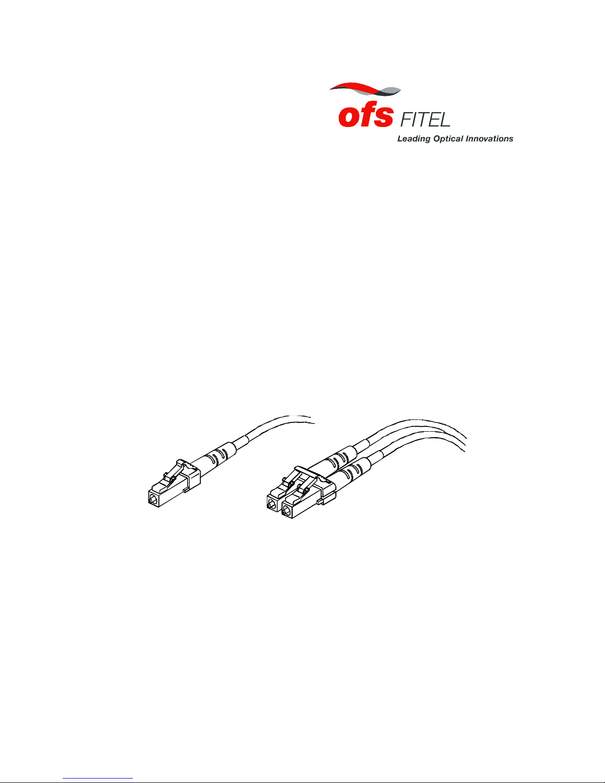
Removable
Cable Supports
Cable Support
Crimp Sleeve
Connector
Simplex Jumper Components* Duplex Jumper Components
*Available one per package for simplex cord and two per package for SM duplex cord.
Regular
Duplex Yoke
Connectors
Note: In addition to the simplex and duplex LC jumper connect or s for 1.6-mm MiniCord
Duplex Yoke
Crimp Sleeves
jumper cords, a Behind-T he- Wall (BT W) c onnec tor is of fered for 0.9-mm buffered fiber.
Installation of the BTW connector is not covered in this customer information pr oduc t
(CIP). The BTW connector c an be used to terminate Outside P lant (OS P ) c ables as well
as building c ables.
When install ed on typical fi ber , the f ollowing performanc e shoul d be obtained:
Multimode
Insertion loss (avg.) = 0.1 dB
Return loss ≥ 30 dB
Singlemode
Insertion loss (avg.) = 0.2 dB
Return loss ≥ 50 dB
1.2 Epoxy Consumables
Kit Type (Note) Kit Number Comcode Kit Includes
Multim ode D-182983 108 340 811 Polishing paper, epoxy, and other materials
required to assemble 200 multi mode connectors.
Singlemode D-182977 108 338 591 Polishing paper, epoxy, and other materials
required to assemble 200 singlemode connectors.
Note: Kits do not contain connectors, isopropyl al cohol , or nonozone-depleting canned air.
1.3 Epoxy Tool and Upgrade Kits
Kit Type (Note) Kit Number Comcode Kit Includes
Epoxy Tool Kit 1032B5 106 705 213 110-volt curi ng oven
Epoxy Tool Kit 1032B6 106 919 012 220-volt curi ng oven
Note: In addition to t he tool kit, the D-182959 Upgrade Kit (108 262 569) i s also required.
- 1 -
- -
1.4 Ordering Information
Section 11 contains ordering information for LC connectors and kits.
2. Safety Precautions
• Safety glasses should be worn at all times while perform ing the installation procedures.
• Avoid skin contac t with the epoxy.
• Place combustibles away f r om the curing oven when it is in operation. After t he oven
has reached its operating temperature, the oven ports and heat tube assemblies are
extremely hot [266°F (130°C)] . Allow the oven and heat tube assemblies to c ool before
handling or stor ing.
• Optical fibers may emit radiation if t he far end i s connected to a working l aser or LightEmitting Diode (LED). Never view the fiber end of a cable or plug with the naked ey e
or any optical instrument until absolute verifi c ation is establ ished that the fiber is
disconnected from any laser or LED source.
3. Oven Preparation
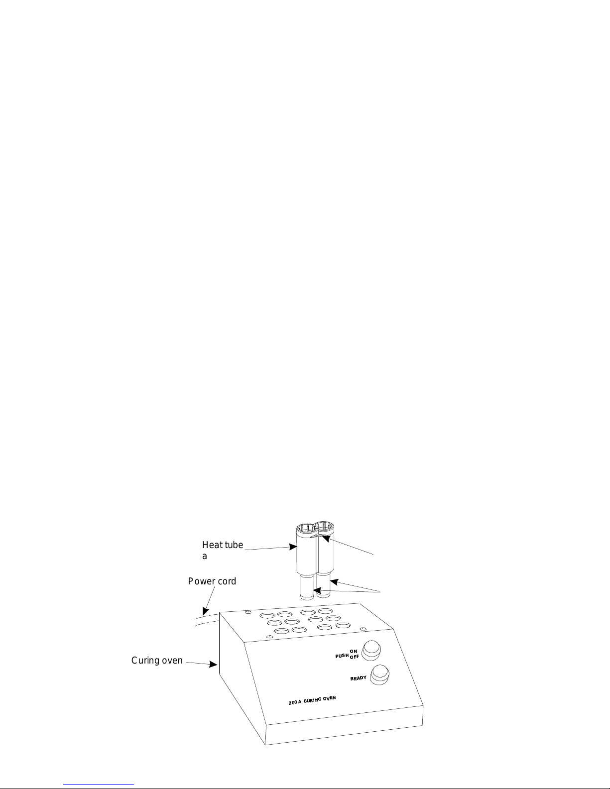
3.1 Set Up Curing Oven
1. Place oven on a level surface and away fr om com bustibles.
2. Connect the power cord to a power source (120 V 60 Hz A C for the 200A oven and 220 V 50
Hz AC for the 200Al i nternational ov en) .
3. Locate the six heat tube assembl ies (108 261 835) supplied wit h the D-182959 Upgrade Kit
(108 262 569).
4. Insert the heat t ube assem blies into the heater ports.
Note: Be cert ain that t he metal por tion of each heat tube assembly is fully inserted into the
heater ports.
5. Push the ON/OFF switch to the ON position (lamp in switch illuminates).
Note: A READY lamp will illuminate when the oven reaches its operating tem per ature of
266°F ( 130°C).
Caution: After the oven reaches it s operat ing tem per ature, the metal portion of the heat
tube assembly will be extremely HOT [266°F (130°C)]. A llow the oven and heat
tube assemblies to cool before handl ing and storing.
Heat tube
assembly
Power cord
Lifting lug (one on each
side of heat tube assembly)
Met al por ti on
of heat tube
assembly
1
2
+
6
8
3
)
)
Curi ng ov e n
*
,1
5
8
&
$
2
<
'
$
(
5
1
(
9
2
- 2 -

4. Cord Preparation
4.1 Assemble Connector Components
4.1.1 Simp lex Applications on a S implex Cord
1. Thread a cable support onto the simplex cor d, narrow end fi r st.
2. Thread a cri mp sleeve onto the cor d. The met al end of the crimp sleeve should be orient ed
toward the end of t he cord.
3. Repeat Steps 1 and 2 for the other end of the cord.
Narrow end of
cable support
Cable support
Metal end of
crimp sleeve
Crimp sleeve
4.1.2 Singlemode Simplex Application s on a Dupl ex Cord
1. Split the jacket on the duplex c or d into two separate cords at least 9 inches (230 m m) f r om
the end.
2. Thread a cable support onto each cord, narrow end first.
3. Determine the buf fer col or of each cor d by looking into the end of the cordage. The duplex
cord should have a blue buffer and an orange buffer.
4. Thread a yellow crimp sl eeve on t he c or d with the blue buffer and a white crimp sleeve on
the cord with t he or ange buff er . The metal end of the crimp sleeve should be orient ed toward
the end of t he c or d.
5. Repeat Steps 1 through 4 for the other end of the cor d.
Cabl e support
Crimp sleeve
(white)
Cable support
Crimp sleeve
(yellow)
Orange buffer
Blue buffer
- 3 -
- -
Blue buffer
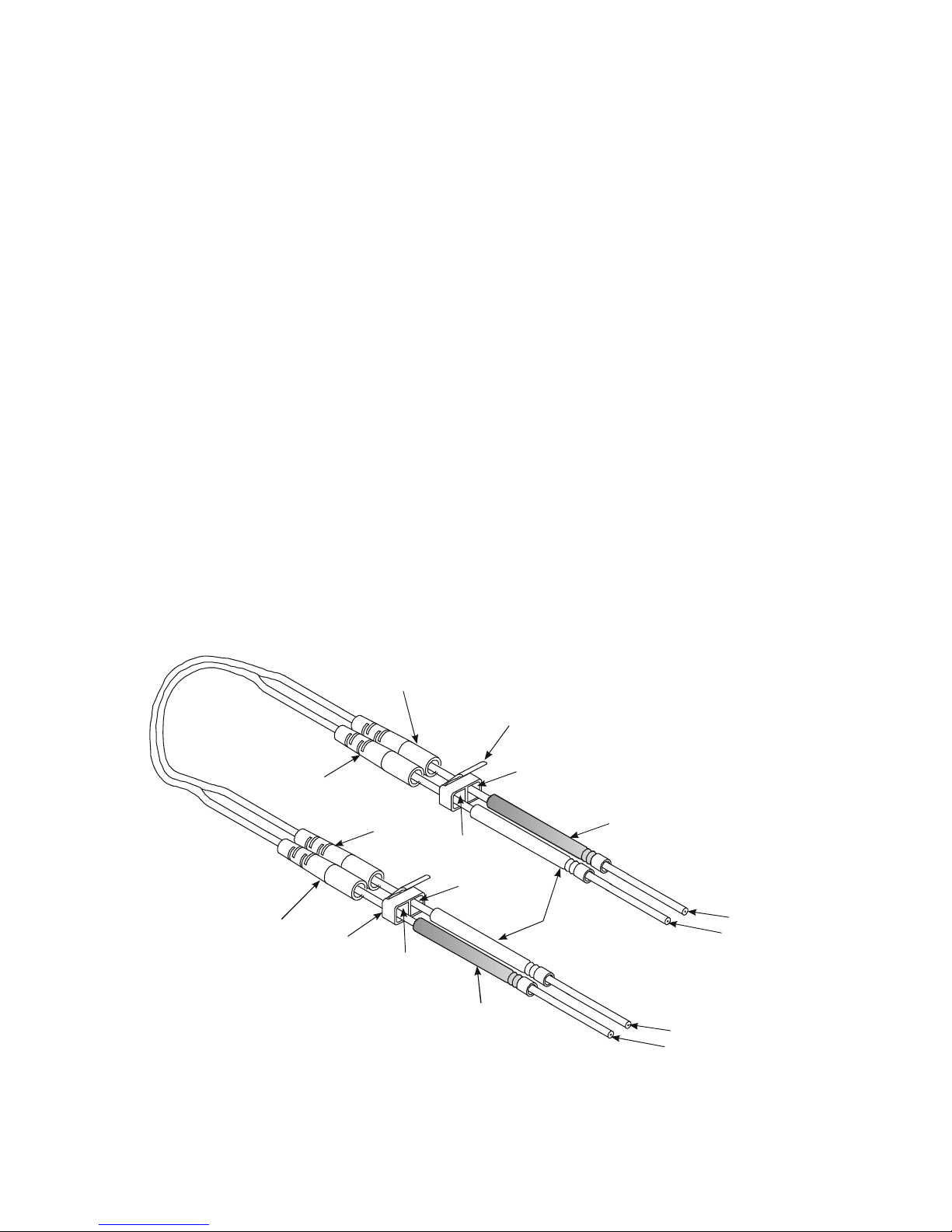
4.1.3a Duplex Applications on a Duplex Cord (with Regular Duplex Yoke)
1. Split the jacket on the duplex c or d into two separate cords at least 9 inches (230 m m) f r om
the end.
2. Thread a cable support onto each cord, narrow end first.
3. Determine the buf fer col or of each cor d by looking at the end of the c or dage. The duplex
cord should have a blue buffer and an orange buffer.
4. Locate the B channel opening on the duplex yoke.
5. At the first end, thread the cord wit h the blue buf fer thr ough the B channel opening.
6. Locate the A channel opening on the duplex y ok e.
7. Thread the cord with the orange buf fer thr ough the A channel opening.
8. Place a yellow crimp sleeve on the cord with the blue buf fer and a white c r imp sleeve on the
cord with the orange buff er . The metal end of the crimp sleeves should be oriented t oward
the end of t he c or d.
9. On the opposite end of the dupl ex cord, spl it the j ac k et into t wo separate cords at least 9
inches (230 mm) f r om the end.
10. Thread a cable support onto eac h c ord, narrow end first.
11. Determine whic h c ord has the blue buf fer and which cor d has the or ange buffer.
12. Locate the A channel opening on the duplex yoke.
13. Thread the cord with t he blue buffer through the A channel opening.
14. Locate the B channel opening on the dupl ex yoke.
15. Thread the cord with t he orange buffer through the B channel opening.
16. Place a yellow crimp sl eeve on t he c or d with the blue buffer and a white crimp sleeve on the
cord with the orange buff er . The metal end of the crimp sleeves should be oriented t oward
the end of t he c or d.
Cable support
Cable support
Cable support
Cable support
Duplex yoke
A
channel
opening
Duplex yoke
A
channel
opening
B
channel
opening
Crimp sleeve
(yellow)
B
channel
opening
Crimp sleeve
(white)
Crimp sleeve
(yellow)
Blue buffer
Orange buffer
Orange buffer
- 4 -
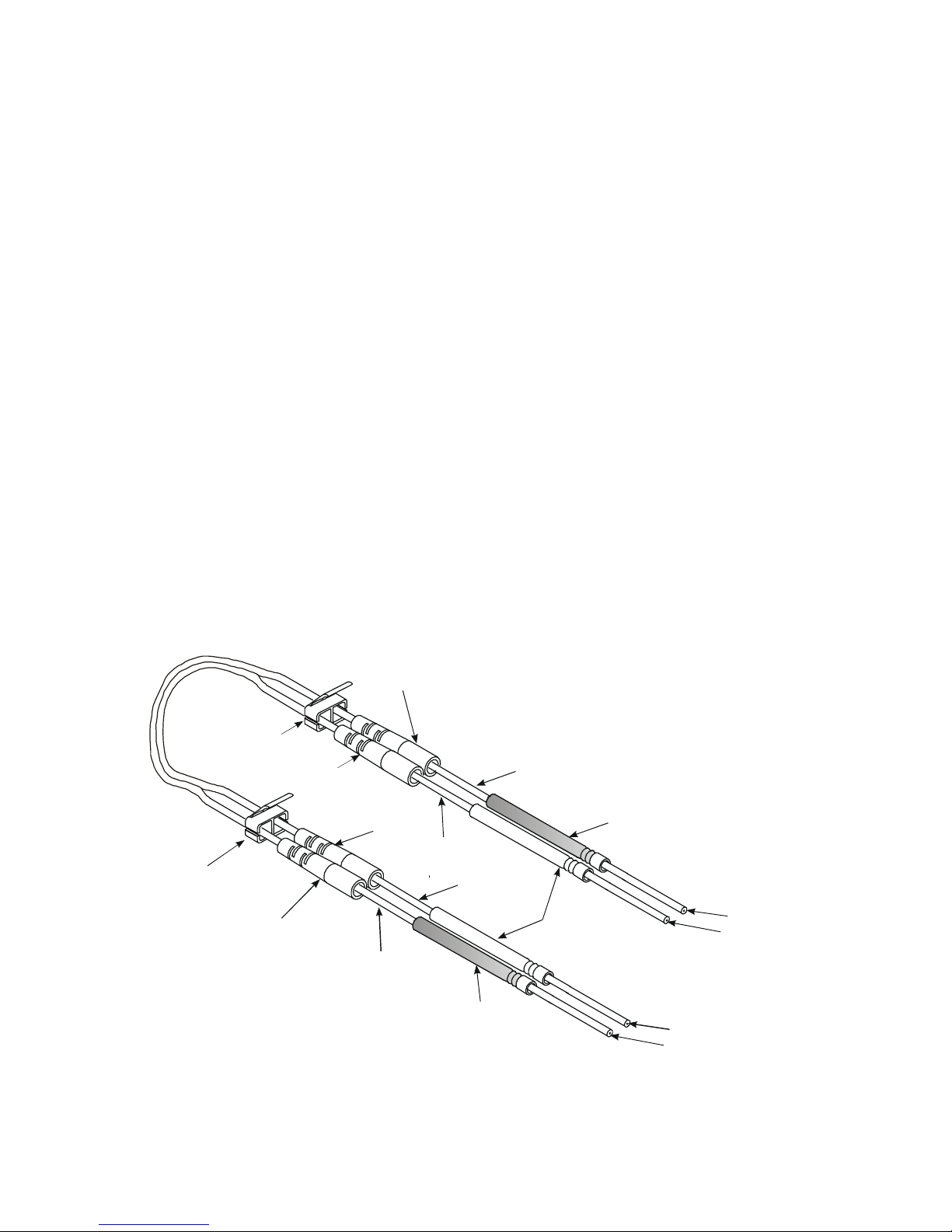
4.1.3b Duplex Appli cat ions on a Duplex Co rd (with Replaceabl e Duplex Yo ke)
1. Split the jacket on the duplex c or d into two separate cords at least 9 inches (230 m m) f r om
the end.
2. Determine the buf fer col or of each cor d by looking at the end of the c or dage. The duplex
cord should have a blue buffer and an orange buffer.
3. Locate the B channel opening on the duplex yoke.
4. At the first end, thread the cord wit h the blue buf fer thr ough the B channel opening.
5. Locate the A channel opening on the duplex y ok e.
6. Thread the cord with the orange buf fer thr ough the A channel opening.
7. Thread a cable support onto each cord, narrow end first.
8. Place a yellow crimp sleeve on the cord with the blue buf fer and a white c r imp sleeve on the
cord with the orange buff er . The metal end of the crimp sleeves should be oriented t oward
the end of t he c or d.
9. On the opposite end of the dupl ex cord, spl it the j ac k et into t wo separate cords at least 9
inches (230 mm) f r om the end.
10. Determine whic h c ord has the blue buf fer and which cor d has the or ange buffer.
11. Locate the A channel opening on the duplex yoke.
12. Thread the cord with t he blue buffer through the A channel opening.
13. Locate the B channel opening on the dupl ex yoke.
14. Thread the cord with t he orange buffer through the B channel opening.
15. Thread a cable support onto eac h c ord, narrow end first.
16. Place a yellow crimp sl eeve on t he c or d with the blue buffer and a white crimp sleeve on the
cord with the orange buff er . The metal end of the crimp sleeves should be oriented t oward
the end of t he c or d.
Removable
Duplex yoke
Removable
Duplex yoke
Cable support
Cable support
Cable support
Cable support
channel
A
opening
channel
A
opening
channel
B
opening
Crimp sleeve
(yellow)
channel
B
opening
Crimp sleeve
(white)
Crimp sleeve
(yellow)
Blue buffer
Orange buffer
Orange buffer
Blue buffer
- 5 -
- -

4.2 Remove Outer Jacket and Trim Strengthening Yarn
1. Locate the template and pen pr ovi ded in the D-182959 Upgrade Kit (108 262 536).
2. Measure and mark out er jacket at 1.125 inches (28.5 mm) and at 1.375 inches (34.9 mm)
from the end.
1.375 inche s
(34.9 mm)
1.125 i nches
(28.5 mm)
3. Use the 700A strippi ng tool to remove outer jack et at the 1.125 inches (28.5 m m) mar k .
Stripping tool
(b lue handl es)
Number 1
notch
Outer jacket
being removed
4. Lightly twist the strengthening yarn int o one bundle and use scissors to cut yarn flush with
the end of t he outer jacket.
Buffered
fiber
Outer jacket
Cut strengthening yarn
flush with outer jacket
- 6 -

5. Use the 700A strippi ng tool to remove outer jack et at the 1.375 inches (34.9 m m) mar k . This
will expose 0.25 inch (6.3 mm) of yarn.
Stripping tool
(blue handles)
Number 1
notch
Outer jacket
being removed
6. Flare the shortened strengthening yar n evenly around the cable. The brush f r om the 1026A
stripper tool can be used.
4.3 Remove Buffer and Fiber Coating
Note: Ref er to 1026A Heat-St r ip Tool oper ating instruc tions for heat-strip t ool setup.
1. Locate the 1026A Heat- Strip T ool (105 514 764) provided in the 1032B5 Tool Kit
(106 705 213) or in the 1032B 6 Tool Kit (106 919 012).
2. Locate the gold LC stripper guide tube ( 108 262 577) provided in D-182959 Upgrade K it.
3. Install the heat-stri p tube into t he heat-strip tool making sure the heat-strip tube is fully
inserted into the heat-strip tool.
4. Insert buffered fiber i nto the guide t ube until the jacket and str engthening yarn hit the
appropriate stop inside the guide tube.
Note: Do not force the cor d into the gui de tube. If the buf fer does not go thr ough the guide
tube easily, trim 0.03125 inch (0. 794 mm) from end of buffer . The end of the buffer
occasionall y bec omes fl attened when the cord is i nitially cut. The buffered fiber
should protrude approximately 0.55 inch (14 mm) into the guide tube.
Caution: Proper stripping lengths and procedures are required for best connect or pull-proof
performance.
- 7 -
- -
 Loading...