

IMPULSE G2/PULSE
INSTRUCTIONS
TOOLS REQUIRED:
1608990
Rev:
Dwg:
INSTRUCTIONS
Outside Access
Panel
1608990
Rev:
Dwg:
STATIC BRIDGE & RETURN MODULE
INSTALLATION INSTRUCTIONS
PART # 1608990
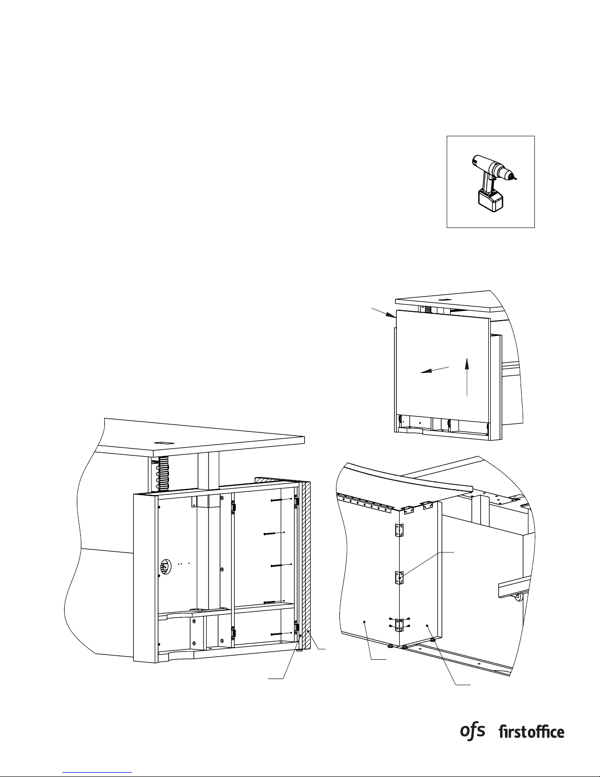
1. This sheet covers the steps to install a static bridge or return module
with the “FX” no hinged access panel back option to a height adjustable
freestanding desk.
2. Begin by removing the outside access panel on the connecting end of
the desk. The access panel can be removed by lifting upwards and then
outward as illustrated in the upper most view. Next, remove the two
outer most factory installed screws on the connecting panel of the desk,
as shown in the view below. The inner most screws will be removed at a
later time.
3. Locate the loose support panel included with your height adjustable
desk. Place it directly against the connecting end of the desk, making
sure the bottom edges are flush with each other, and that the back edge
will align with the face of the access panel. Secure the panel in place
by fastening the supplied wood screws from the HK-67 kit through the
clearance holes and into the support panel, as shown below. A pilot hole
can be drilled prior to fastening the screws. Repeat the process for the
remaining inner most screws. The access panel can now be re-installed.
4. Position the bridge/return next to the desk, making sure all are aligned
with each other and level. Once the modules are in their correct position,
fasten together by using the supplied “L” brackets and wood screws from
the HK-10 kit as shown below.
Drill
Outside Access
Panel
Outside
Access
Panel
Tools Required:
TOOLS REQUIRED:
Drill
Drill
Desk Connecting Panel
Desk
Connecting
Panel
Support
Support
Panel
Panel
Bridge
Bridge
Back Panel
Back
Panel
"L" Bracket
“ L”
Bracket
Support
Support
Panel
IMPULSE G2/PULSE
INSTRUCTIONS
TOOLS REQUIRED:
1608991
Rev:
Dwg:
INSTRUCTIONS
Outside Access
Panel
1608990
Rev:
Dwg:
STATIC BRIDGE & RETURN MODULE
INSTALLATION INSTRUCTIONS
PART # 1608991
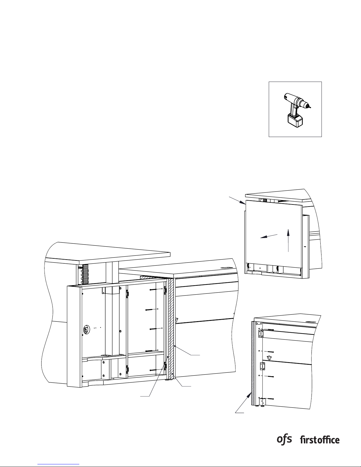
1. This sheet covers the steps to install a static bridge or return module
with the “FZ” hinged access panel back option to a height adjustable
freestanding desk.
2. Begin by locating the loose support panel included with your height
adjustable desk. Place it directly against the connecting end of the
bridge/return making sure the back and bottom edges are flush with
each other as shown in the view below. Secure the panel in place by
fastening the supplied wood screws from the HK-48 kit through the
mounting holes in the bridge/return and into the support panel.
3. Next, remove the outside access panel on the connecting end of the
desk. The access panel can be removed by lifting upwards and then
outward as illustrated in the upper most view. Remove the two outer
most factory installed screws on the connecting panel of the desk, as
shown in the view below. The inner most screws will be removed at a
later time.
4. Position the bridge/return next to the desk, making sure all are aligned
with each other and level. Once the modules are in their correct position,
fasten together by screwing the supplied wood screws from the HK-67
kit through the clearance holes and into the support panel. A pilot hole
can be drilled prior to fastening the screws. Repeat the process for the
inner most screws. The access panel can now be re-installed.
Drill
Outside
Outside Access
Access
Panel
Panel
Tools Required:
TOOLS REQUIRED:
Drill
Drill
Desk Connecting Panel
Desk
Connecting Panel
Connecting Panel
Support
Support
Panel
Panel
Bridge
Bridge
Connecting
Panel
Support
Support
Panel
Panel

IMPULSE G2/PULSE
INSTRUCTIONS
FREESTANDING TABLE
ASSEMBLY
Place work surface bottom side
•
up on a non-marring surface.
Align holes on mounting plate
•
with pre-drilled holes on bottom
side of work surface.
Fasten mounting hardware to
•
worksurface using (8) #12 X 1"
truss head screws per column.
Rev:
Dwg:
Rev:
Dwg:
Place work surface bottom side
Align holes on mounting plate
Fasten mounting hardware to
Rev:
Dwg:
INSTRUCTIONS
FREESTANDING TABLE
ASSEMBLY
Attach mounting hardware to
•
top of columns.
Use (4) M6 x 16MM flat head
•
cap screws, per column ,to
attach mounting plate to top
of column.
Place work surface bottom side
•
up on a non-marring surface.
Align holes on mounting plate
•
with pre-drilled holes on bottom
side of work surface.
Fasten mounting hardware to
•
worksurface using (8) #12 X 1"
truss head screws per column.
Align bolt holes in feet with
•
threaded holes in the
bottom of columns.
Attach feet to columns using
•
(4) M6 x 20MM socket head
cap screws per column.
Rev:
Dwg:
FREESTANDING TABLE
INSTALLATION INSTRUCTIONS
1. Attach mounting hardware to top of columns.
2. Use (4) M6 x 16MM flat head cap screws, per
column, to attach mounting plate to top of
column.
Cordless Screwdriver
Tools Required:
Required Tools:
Cordless Screwdriver
5mm Allen Wrench
5mm Allen Wrench
Level
Level
PART # 1608995
3. Place work surface bottom side up on a nonmarring surface.
4. Align holes on mounting plate with predrilled holes on bottom side of worksurface.
5. Fasten mounting hardware to worksurface
using (8) #12 X 1" truss head screws per
column.
6. Align bolt holes in feet with threaded holes in
the bottom of columns.
7. Attach feet to columns using (4) M6 x 20MM
socket head cap screws per column.
PAGE 1 OF 3

IMPULSE G2/PULSE
INSTRUCTIONS
ASSEMBLY
Rev:
Dwg:
INSTRUCTIONS
CONTROL BOX
CONTROL PANEL
FREESTANDING TABLE
ASSEMBLY
Rev:
Dwg:
FREESTANDING TABLE
INSTALLATION INSTRUCTIONS
8. Align two thru holes in control box with
pre-drilled holes on bottom side of work
surface.
9. Use (2) #8 x 2" pan head screws to secure to
worksurface.
10. To attach control panel, determine if control
panel is to be on the left or right side of the
worksurface.
11. Align control panel mount plate with
pre-drilled holes.
CONTROL PANEL
CONTROL BOX
Control Box
Control Panel
12. Use (2) X8 x 5/8" pan head screws to secure
to worksurface.
NOTE: When attaching control box, use
NOTE: When attaching control box, use the grooves on
the grooves on the upper face to help
the upper face to help manage motor cables.
manage motor cables.
PAGE 2 OF 3
Use “hook” for mains cable
Use "hook" for mains cable
(power cord) relief.
(power cord) relief.

IMPULSE G2/PULSE
INSTRUCTIONS
FREESTANDING TABLE
ASSEMBLY
Rev:
Dwg:
FREESTANDING TABLE
INSTALLATION INSTRUCTIONS
13. Snap together motor cable ends and leg cables. (Figure A)
14. Plug the other end of the motor cable to the control box.
15. Plug control panel cord into control box.
16. Last, plug in mains cable to control box.
17. Secure cables using provided cord clips and velcro strips.
Leg Cable
Mains
Mains
Cable
Cable
Control
Control
Panel
Panel
Cord
Cord
Figure A
Figure A
18. Table must be completely leveled before use.
19. Adjust levelers by turning them in or out.
20. Table must be level from side to side and front to back.
PAGE 3 OF 3
Motor Cable
Motor Cable

IMPULSE G2/PULSE
INSTRUCTIONS
Worksurface Location
1609011
Rev:
Dwg:
INSTRUCTIONS
Outside Access
Panel
1608990
Rev:
Dwg:
HEIGHT ADJUSTABLE DESK
SET UP GUIDE
PART # 1609011
1. This sheet covers the details to correctly set up your height adjustable unit.
2. The control switch has been temporarily mounted in a protected area underneath the worksurface to
prevent any damage during shipping. Remove the mounting screw(s) and place the switch in a visible
and obstruction free postion. Fasten the switch to the worksurface utilizing the two mounting holes on
the bracket. NOTE: It is recommended to use a power supply (PS-77) to power the height adjustable
unit if any electrical accessories are installed onto it. This will aid in the process of properly
managing power cords underneath the worksurface.
3. A wire manager is included to use with your desk and is intended to be installed in between the
worksurface and fixed shelf. To assemble the wire manager, slide the mounting clip onto the manager
as shown in the views below. The slot on the clip aligns with the flat narrow sections of the manager.
4. The wire manager can be installed on either the left or right side of the fixed shelf, near the corner
notches. Raise the worksurface to the upper most height, then locate an area above and below that
will allow for a clear mounting position. Approximate locations are shown in the views below. Fasten
the mounting clips, making sure the mounting clips are relatively straight and parallel with each
other. This will ensure that the wire manager will not bind or stress when the worksurface is lowered.
5. Wires and cables can then be passed
through the wire manager, the notch
TOOLS REQUIRED:
of the shelf, and finally routed through
the pedestal and/or base as illustrated
in the views below. To gain access
inside the panel base, lift upward and
then outward on the outside end panel
and set aside.
Drill
Desired
Desired
Location
Location
Factory
Installed
Factory Installed
Location
Location
Tools Required:
TOOLS REQUIRED:
Drill
Drill
PS-77
PS-77
Mount
Mount
Clip
Clip
Wire Manager
Wire Manager
Wire Manager shown
Wire Manager shown
installed on the right side
installed on the right side
Lower Position
Lower Position
Upper Position
Upper Position
Worksurface Location
Power Cord
Power Cord
Shelf Location
Shelf Location
 Loading...