

Ofna Racing DM-ONE-SPEC e, 34328 Instruction Manual


IMPORTANT-READ THIS BEFORE RUNNING
1.Before Starting
•If you are under 18 please read manual (with a parent, guardian or a responsible adult if necessary).
2.While Operating
•Any running area you choose must be dry. Do not run car near any water or wet dirt.
•Do not run on public streets. It is very easy to have the car run over or be damaged by hitting the curb.
•Do not operate the car in tight confined space. The car is very fast and will easily hit something.
•Do not run near people or animals. The car is very fast and could easily hit someone if you are not an
expert driver.
•Do not operate the car at night. You will not be able to drive it safely.
3.Before Operating
•Make sure that all screws and nuts are properly tightened.
•Radio-Check battery life before running the car. If the radio does not have full control of the car with
steering and/or throttle/brake, do not run until corrected. Failure to correct this will result in possible
injury and damage to the car or property.
•Please confirm the neutral throttle trigger position.
4.Check Your Car After Running
•Turn OFF receiver first, then turn OFF transmitter. This will prevent the car from losing control.
•After running radio controlled car , it is necessary to perform routine maintenance.
5.Battery Safety
•Please be careful when handling the battery. It will be hot after running. If the wire is frayed, a short
circuit can cause a fire.
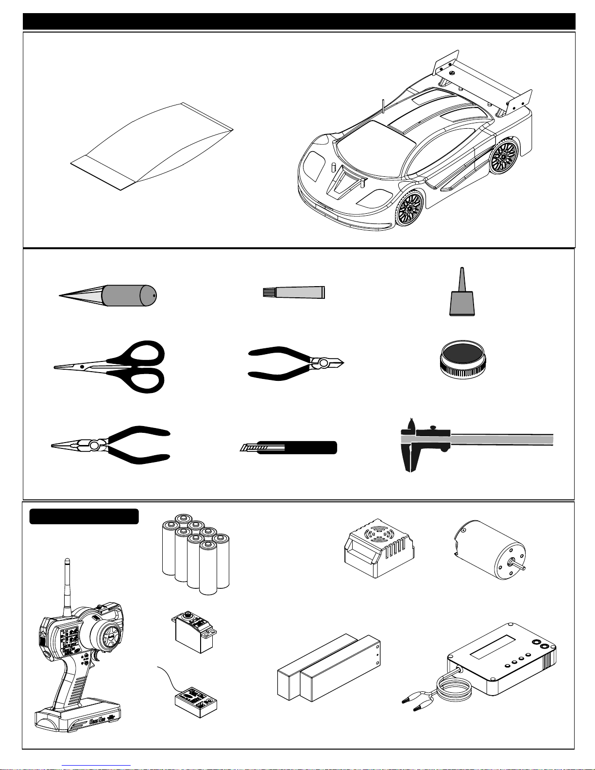
Components
Parts Bag
Body Reamer
OVERVIEW
Radio Control Car
TOOLS NOT INCLUDED IN THE KIT
Screw Cement
Screw Cement
CA
Instant Cemment
Curved Scissors
Needle Nosed Pliers
Equipment Needed
Transmitter
Cutter
Craft Knife
UM-3 Batteries
( 8pcs )
Brushless Electric
Speed Controller
GEAR
GREASE
Gear Grease
Precision Caliper
Brushless Motor
Servo
Receiver
7.4V L i-Po Battery(Hard Case)
L Battery Chargeri-Po
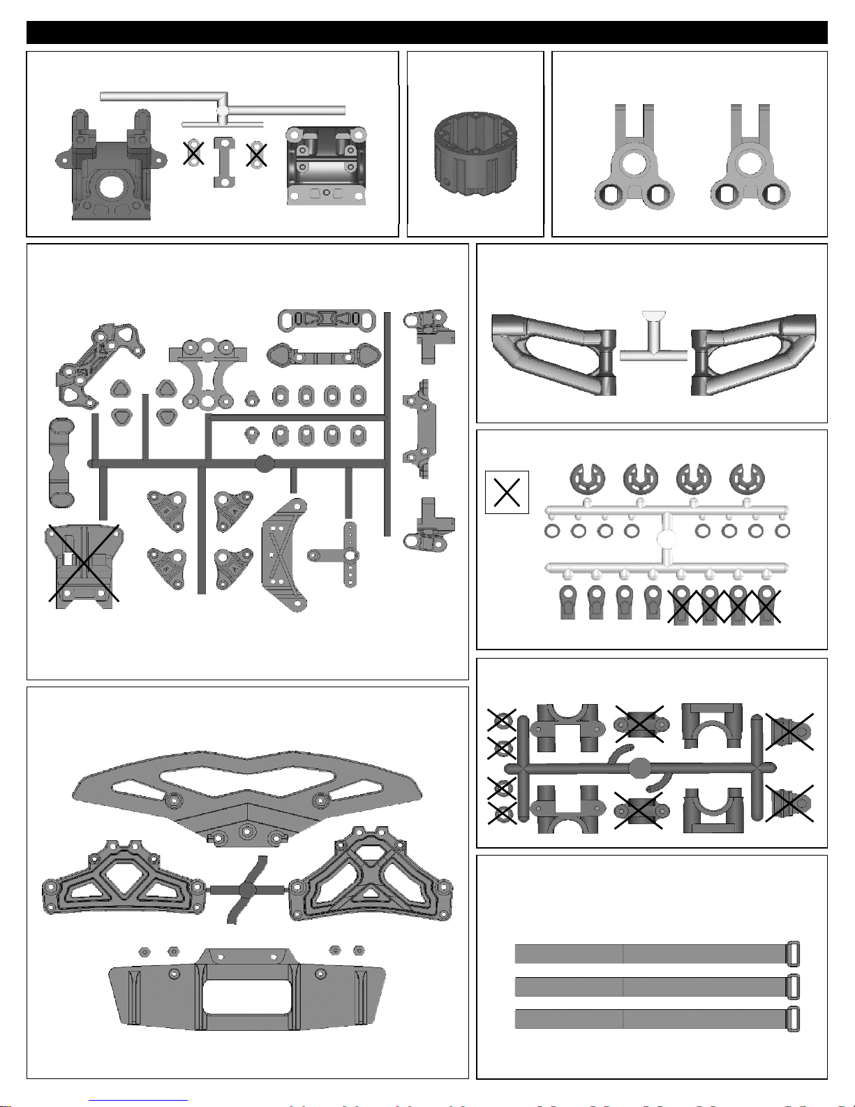
PLASTIC PARTS FOR USE
40533
FRONT AND REAR GEAR BOX
4071940719
ARM HOLDER
40538
DIFF. CASE
40537
REAR UPPER ARM
40643
SHOCK PLASTIC
31304
REAR UPRIGHT
40721
FRONT BUMPER
Parts for
Not Use
40040
CENTER DIFF. MOUNT PLASTIC PARTS
30663
VELCRO BATTERY STRAPS

PLASTIC PARTS FOR USE
30662
BATTERY CASE
40717
FRONT AND REAR LOWER ARM
40539
SERVO SAVER
40718
FRONT KNUCKLE ARM
40720
SIDE IMPACT BUMPER AND BODY POST
SYMBOL USED THROUGHOUT THE INSTRUCTION MANUAL
Degrease With
Motor Spray
Apply OilApply Screw
BAG
S
C
ew
cr
ent
em
Parts Bag Used
Cement
Oil
Do Not
Over Tighten
Apply
Grease
40716
FRONT UPPER ARM
Do Not
Over Tighten
Apply Grease
Tighten
1:1
Tighten
True-To-Scale
Ensure
Free
Movement
Rotate
Direction
Ensure Free
Movement
Clockwise
Rotation
Contact
Adhesive
Rotate
Direction
Contact Adhesive
Anti-clockwise
Rotation
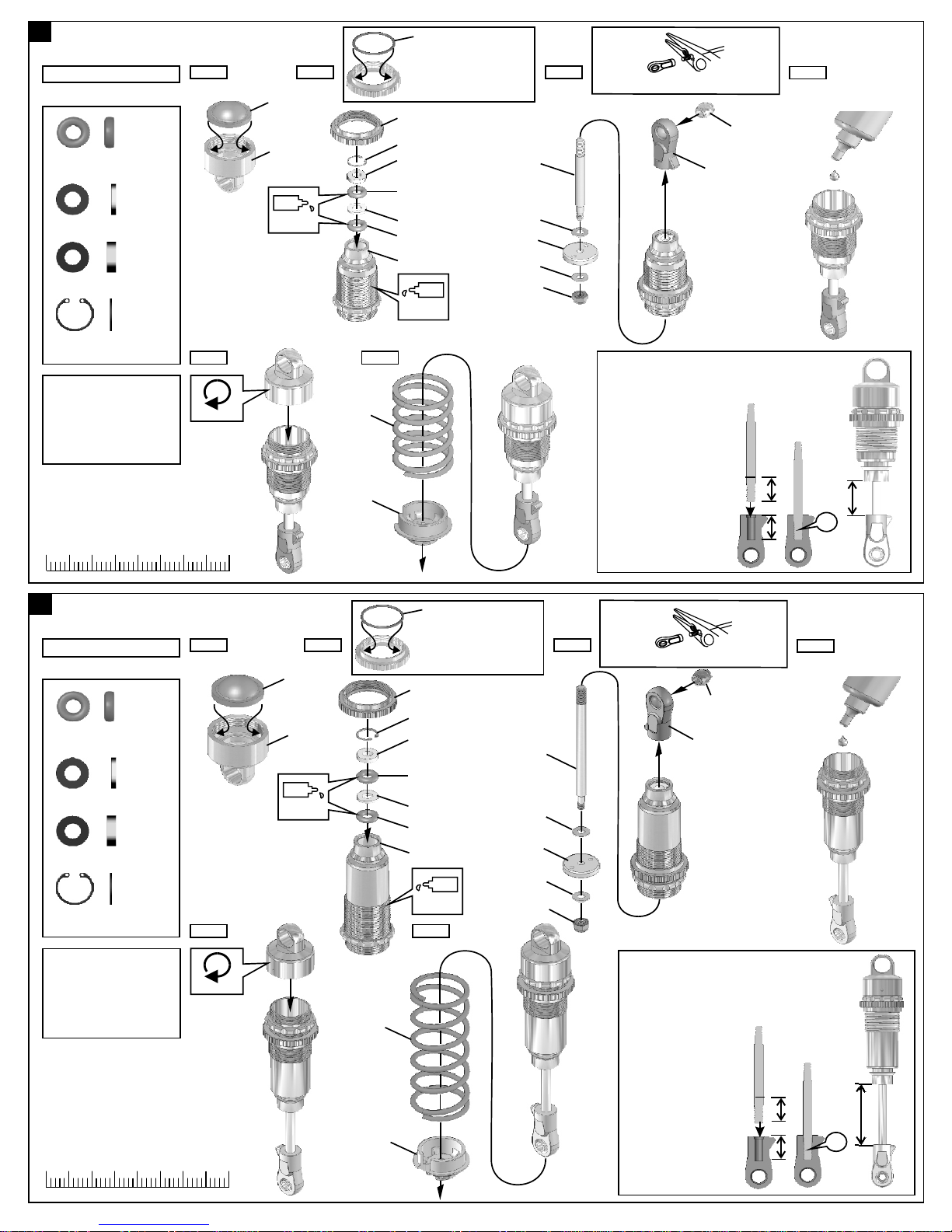
1
ASSEMBLY OF THE FRONT SHOCKS
•Assemble 2 seets for front
40090
3.5mm O-Ring
40090
1mm Washer
40090
2mm Washer
40090
7mm R-Ring
1.Pull down piston and pour
oil into shock cylinder.
2.To remove air bubbles by
slowly moving piston up
and down.
3.Pull down piston, attach
pressure top and shock oil
overflow with tissue paper.
.....x4
.....x2
.....x2
.....x2
Step 1 Step 2 Step 3
40640
40633
Oil
Step 5 Step 6
Tighten
40640
40636
•Fit the o-ring into groove
before assembly.
40634
40090
40090
2mm
40090
40090
1mm
40090
40737
Oil
40736
2.6x5mm
40638
2.6x5mm
40060
•Be careful not to damage shock shaft.
30403
40643(Short)
CORRECT SHOCK ASSEMBLY
Carefully screw the shock
shaft into the bottom of the
plastic ball and until the
distance between the ball
end and the shock is 14mm.
Do not over tighten
as the plastic will strip.
Step 4
Fill the shocks with oil #80wt.
.....x4
.....x2
.....x2
.....x2
30
4010
Step 1
Step 5
0 20
2
ASSEMBLY OF THE REAR SHOCKS
*Assemble 2 seets for rear
40090
3.5mm O-Ring
40090
1mm Washer
40090
2mm Washer
40090
7mm R-Ring
40640
40633
Oil
Step 2
40643
40636
•Fit the o-ring into groove
before assembly.
40634
40090
40090
2mm
40090
40090
1mm
40090
40632
Step 6
Oil
40054
2.6x5mm
40638
2.6x5mm
40060
Step 3
•Be careful not to damage shock shaft.
30403
40643(Short)
14mm
OK
Step 4
Fill the shocks with oil
#60wt.
1.Pull down piston and pour
oil into shock cylinder.
2.To remove air bubbles by
slowly moving piston up
and down.
3.Pull down piston, attach
pressure top and shock oil
overflow with tissue paper.
0 20
30
Tighten
4010
40751
40643
CORRECT SHOCK ASSEMBLY
Carefully screw the shock
shaft into the bottom of the
plastic ball and until the
distance between the ball
end and the shock is 32mm
Do not over tighten
as the plastic will strip.
32mm
OK
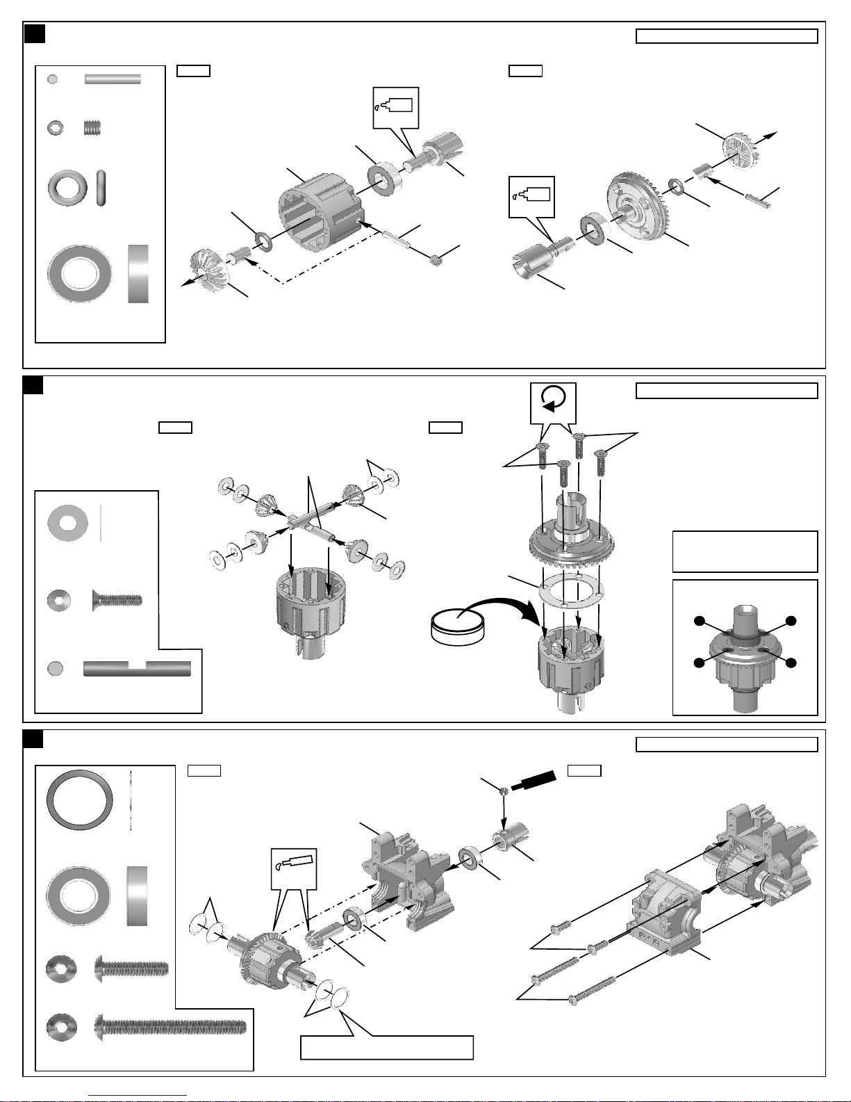
3
ASSEMBLY OF THE FRONT AND REAR DIFF.
Step 1 Step 2
40010
2.5x13.8mm Pin
94034
4x4mm
Set Screw
.....x4
.....x2
40538
36053
Oil
40514
Builds two differentials for front and rear.
40513
40010
40009
P6 O-Ring
36053
8x16mm
Ball Bearing
4
ASSEMBLY OF THE FRONT AND REAR DIFF.
30776
4x10mm
Washer
.....x4
.....x4
Step 1 Step 2
.....x16
40009
40513
30773
30776
40513
40010
4x4mm
3x12mm
40011
Oil
40514
Tighten
40009
36053
40517(43T)
Builds two differentials for front and rear.
3x12mm
•Put the Diff. Oil #100000 for front
and the #5000 for Rear
•Fill the Diff. case to approx. 80%
with the Diff. Oil
Tight the diff screws in this order.
94020
3x12mm
Flat Head
Hex Screw
30773
4mm
Cross Pin
5
ASSEMBLY OF THE FRONT AND REAR GEAR CASE
40024
13x16x0.2mm
Shim
36053
8x16mm Ball Bearing
94011
4x15mm
Hex Screw
94015
4x35mm
Hex Screw
.....x8
.....x4
.....x8
.....x4
.....x4
.....x4
Step 1 Step 2
40533
Apply
40024
Grease
40516(13T)
40024
•Adjust the backlash with the shims.
36053
D
i
f
f. Oil
5x4mm
4x35mm
36053
4x15mm
r
ce
S
Ce n
40519
w
me t
1
4
Builds two gear case for front and rear.
40533
3
2

6
ASSEMBLY OF THE SERVO SAVER
Step 1
40024
13x16x0.2mm
Shim
.....x2
40037
•Tighten the steering plate hex screw
all way down and then back it off 1/2
40563
Step 2
turn.
40539
Oil
40539
40746
40539
Ensure
Free
Movement
40539
4x8mm
Plastic Flange
Bushing
40037
Steering Plat
Hex Screw
7
ASSEMBLY OF THE SERVO SAVER
.....x2
.....x2
Step 1 Step 2
94041
3mm
Nylon Nut
94003
3x10mm
Hex Screw
40531
Shock Ball
End Post
.....x5
.....x5
.....x2
40719
40024
Rotate
Direction
40500(Black)
40034
Left
3mm
3x10mm
40745
40719
3mm
Right
40539
• Notice the direction of the servo saver connecting plate.
40531
40539
40719
Sr
ce
w
e
m
nC e t
Sc
Cm
w
re
nte
e
90018
3x25mm
Cap Screw
8
ASSEMBLY OF THE SERVO SAVER
94026
4x12mm
Flat Head
Hex Screw
40539
6x10mm
Plastic Bearing
.....x2
.....x2
.....x4
Sc e r
Cem
w
e
nt
*Set the left and right hand side upper arm
adjuster in the same direction.
4x12mm
Screw
em t
C en
3x25mm
40539
40539
40539
40539
40511
9
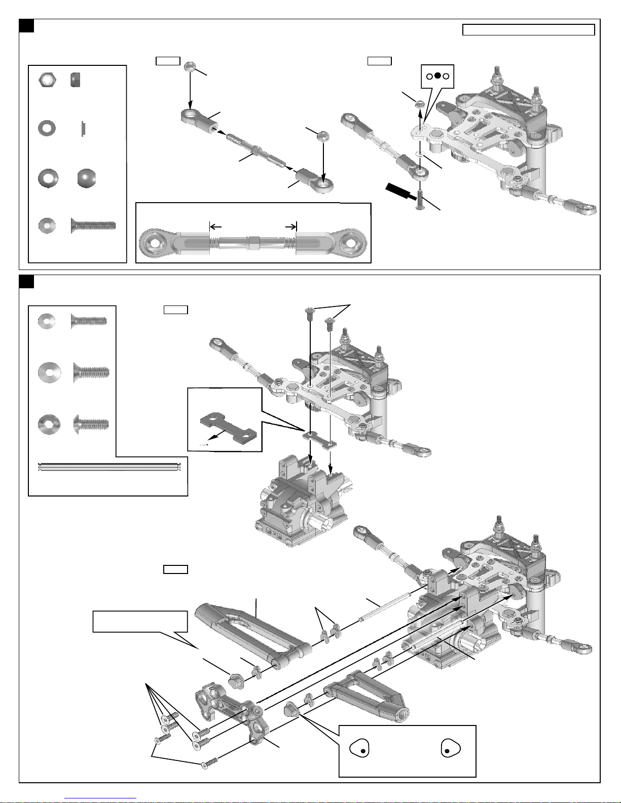
ASSEMBLY OF THE STEERING TIE-ROD
Assemble both right and left side.
Step 1
40038
40548
3mm
Nylon Nut
(Thin Type)
40126
3x6mm
Flange Washer
40038
7mm Ball
.....x2
.....x2
.....x4
36700
40038
36790
36700
1:1
Approx. 29.30 mm
94021
3x15mm
Flat Head
Hex Screw
10
ASSEMBLY OF THE SERVO SAVER AND FRONT UPPER ARMS
94020
3x12mm
Flat Head
Hex Screw
.....x2
Step 1
.....x2
Step 2
4x10mm
40548
c w
C
e
40126
reS
m
e
n
t
3x15mm
94026
4x12mm
Flat Head
Hex Screw
94009
4x10mm
Hex Screw
40525
3x48.1mm
Arm Shaft
.....x4
.....x2
.....x2
*Insert the upper arm adjust
into shock stay.
4x12mm
Step 2
40533
Front Plate Bed
Front
40719
40716
(2mm)
40716
40716
(1mm and 3mm)
40525
40525
3x12mm
40719
Left
•Set the left and right hand side upper arms
adjuster in the same direction.
Right
 Loading...