


BLANK

MUST READ THIS BEFORE RUNNING
Running a nitro kit is fun and easy, but to make this a safe • Clean oil and dirt from chassis with a degreaser like
and good experience you must observe a few rules. This
kit is extremely fast, easily over 40MPH, and can seriously
injure someone if you are not careful.
Where to run car?
• Any running area you choose must be dry. Do not run
car near any water or wet dirt.
• Do not run on public streets. It is very easy to have the
car run over or damaged by hitting the curb.
• Do not operate car in tight confined places. The car is
very fast and will easily hit something.
• Do not run near people or animals.
and will too easily hit someone.
• Due to noise, you will want to consider the surrounding
area when operating the car.
• Do not operate the car at night. You will not be able to
drive it without hitting something.
• Do not operate the car indoors. Engine exhaust is not
healthy.
Glow Fuel
• Glow fuel is poisonous!
• Glow fuel is flammable!
• Do not leave in fuel bottle with lid off at any time. label for additional precautions.
• Do not use any fuel other than glow fuel in this engine.
First Time Starting the Engine
Caution! When starting engine make sure the following is
observed. • Always turn off the car BEFORE turning off radio.
• Set engine Master needle to 3 turns (rich setting)
• Do not do this alone, get an experienced friend to help at • DAMAGE DUE CAR RUN AWAY IS NOT A WARRANTY
first. ISSUE.
• Fill fuel tank, try not to spill fuel. Do not spill fuel on
receiver
• Hold car off the ground, so it will not runaway when first
starts
• Turn on Radio and check the linkage before starting
engine.
• Turn on car receiver battery switch.
• Always have an air filter on the carburetor to keep dirt
out of engine.
Engine Break-in
• See Engine Page.
The car is very fast
Simple Green.
Precautions
• This kit is not a toy. Always run car with a second
person as a spotter and pitman.
• Hot Parts - The pipe, manifold, engine and head are very
hot and will cause burns.
• Rotating Parts - Keep hands away from the drive train,
wheels, and engine when engine is running.
• Radio - Check batteries life before running the car. If
radio does not have full control of the car with steering
and/or throttle/brake do not run until corrected. Failure to
correct this will result in possible injury and damage to the
car or property.
• Glow fuel - Do not leave the glow fuel unattended with
the lid off. Fuel contains Methanol and Nitro Methane
both are flammable and poisonous.
•Store fuel in cool ventilated location. Refer the glow fuel
• Car Fuel tank - Never store fuel in car tank, it will ruin the
engine if left in tank.
IF YOU DO NOT BREAK-IN ENGINE
CORRECTLY, MAINLY AT LOW RPM,
YOU WILL BREAK THE CONNECTING
ROD!
FAILURE TO NOT READ AND
FOLLOW BREAK-IN ENGINE
Emergency Stopping Engine When Running
• Remove air filter and cover carb. intake.
• Squeeze fuel line and hold until engine stops.
• With a rag, cover exhaust outlet.
Storing Car After Running
• Remove fuel from tank and fuel lines
• Turn off radio in car
• Put a few drops of after run in engine to keep it from
rusting.
INSTRUCTIONS WILL VOID
WARRANTY!
CHECK RADIO SETTING,
LINKAGE BEFORE STARTING.
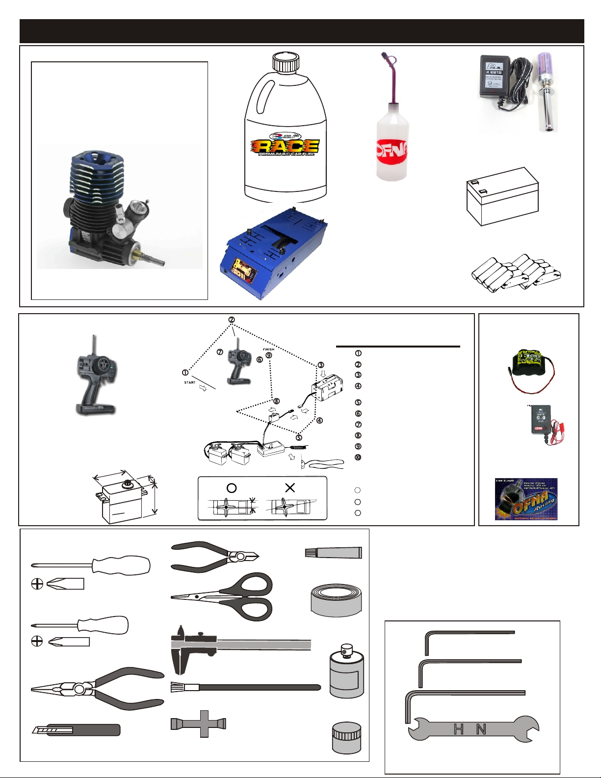
THINGS NEED BESIDES THE KIT
3.5 cc (21 Class) ENGINE
REAR EXHAUST
OFNA/Picco
P-9R EVO
#51219
REQUIRED FOR OPERATION
Glow Fuel
20%
Bottle’s with spout
# 10160 - large 500cc
# 10161 - large 500 ccAuto Stop
# 10162 - small 250cc
# 10164 - CNC spout 500CC
# 10167 - CNC spout 800CC
Glow Plug Long Heat with Battery & Charger
# 10215....$27.95
(please note OFNA Glow Heats available)
Note: Pro kit does not include engine!
RADIO CONTROL UNIT
Note: Carefully read the instruction manual of your
2 channel radio controller before using.
SUITABLE SERVO SIZE
m
m
1
mm-4
36
15mm - 21mm
29mm - 42mm
Off-Road Starter Box, 12V motor
# 10250 - 1/8 scale Starter Box
# 10253 - 1/8 scale Starter Box w/ Panel
Off-Road Starter Box, two 550 motors
# 10248 - 1/8 scale Starter Box
# 10249 - 1/8 scale Starter Box,RTR
Optional Parts
# 92571 - Power Panel Glow Heater
# 92572 - Cable for Glow Plug
Radio must be set at neutral position
before installing in the kit.
SEQUENCE TO SET NEUTRAL
Install AA batteries in Radio.
Extend the antenna.(Transmitter)
Install batteries into Car receiver .
After installing the battery, connect the
battery box.
Extend the antenna. (Receiver)
Set the trim-lever at center.
Turn on the switch. (Transmitter)
Turn on the switch. (Receiver)
Make sure the servos are in command.
When the operation stick is in neutral,
servo horns must be in neutral as will.
*Adjustment can be made by re installing the servo horn.
Turn off the switch. (Receiver)
111111
Turn off the switch. (Transmitter)
12
Retract the antenna. (Transmitter)
13
12V Battery for Starter Box
(must have)
AA Batteries ( 12 pcs ) for radio
More Optional Parts . . .
#10202 NiHm Battery Hump
Pack .. $34.95
# 10214 NiHm Battery Pack
Charger.. $7.95
# 51007 OFNA/Picoo Glow
Plug .. $13.95
TOOLS NOT INCLUDED IN KIT
Phillips Type Screw Drivers ( L )
Phillips Type Screw Drivers ( S )
Needle Nose Pliers
Knife
Cutter
Curved Scissors
Precision Caliper
Brush
Cross Wrench
Instant Cemment
Masking Tape
Paints
INCLUDED WITH KIT
1.5mm Allen Wrench
2mm Allen Wrench
2.5mm Allen Wrench
4mm'5mm Allen Wrench
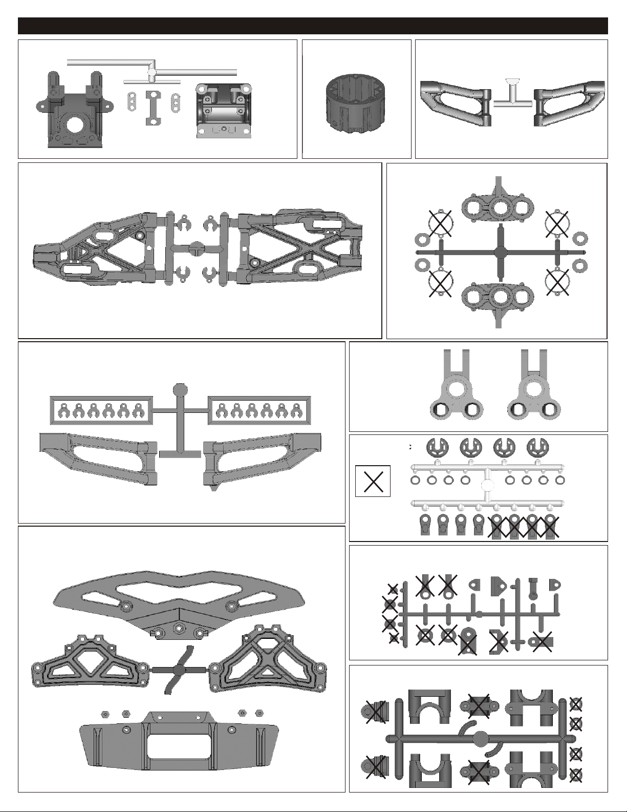
PLASTIC PARTS FOR USE
40533
FRONT AND REAR GEAR BOX
40717
FRONT AND REAR LOWER ARM
40538
DIFF. CASE
40537
REAR UPPER ARM
40718
FRONT KNUCKLE ARM
40716
FRONT UPPER ARM
40721
FRONT BUMPER
31304
REAR UPPER RIGHT
40643
SHOCK PLASTIC
Parts For
Not Use
30800
Throttle Linkage Plastic
40040
CENTER DIFF. MOUNT PLASTIC PARTS
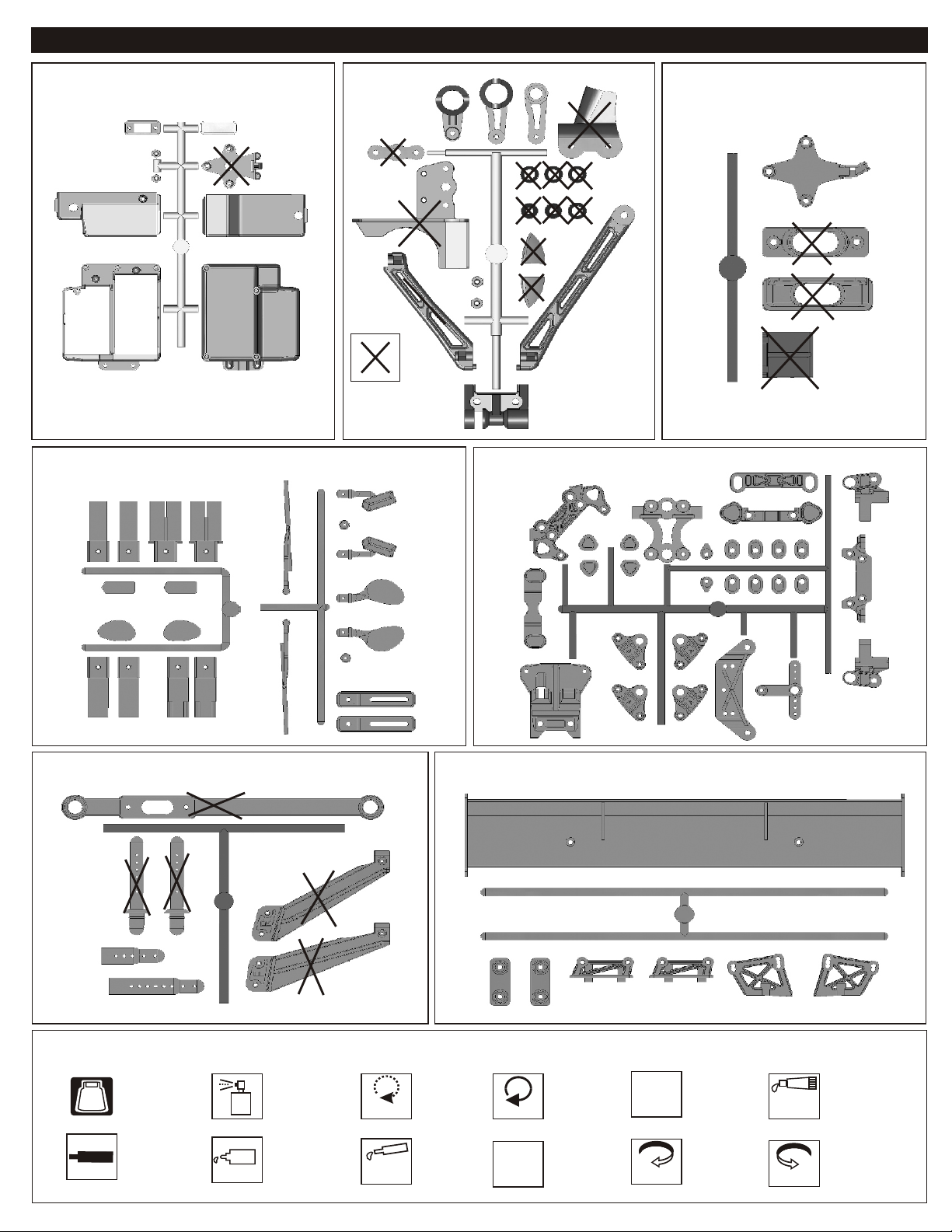
PLASTIC PARTS FOR USE
40541
RECEIVER BOX
40735
EXHAUST PIPE DETAIL PARTS
AND BACK MIRROR
40539
SERVO SAVER
Parts for
Not Use
4071940719
ARM HOLDER
40722
EXHAUST GAS DEFLECTOR
40720
SIDE IMPACT BUMPER AND BODY POST
SYMBOL USED THROUGHOUT THE INSTRUCTION MANUAL
Degrease With
Motor Spray
Apply OilApply Screw
BAG
Sc
C
em nte
rew
Parts Bag Used
Cement
Oil
Do Not
Over Tighten
Apply
Grease
40734
REAR WING AND WING MOUNT
Do Not
Over Tighten
Tighten
Apply Grease
1:1
Tighten
True-To-Scale
Ensure
Free
Movement
Rotate
Direction
Ensure Free
Movement
Clockwise
Rotation
Contact
Adhesive
Rotate
Direction
Contact Adhesive
Anti-clockwise
Rotation
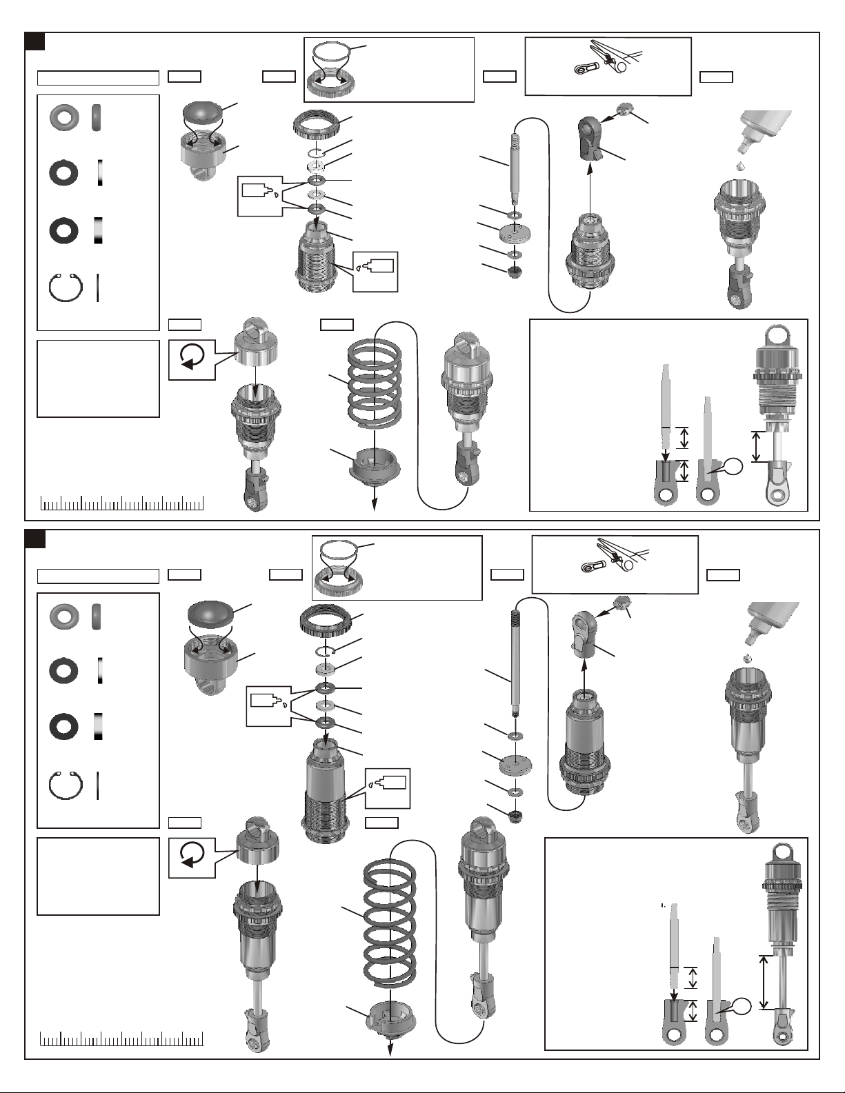
1
ASSEMBLY OF THE FRONT SHOCKS
*Assemble 2 seets for front
40090
3.5mm O-Ring
40090
1mm Washer
40090
2mm Washer
.....x4
.....x2
.....x2
Step 1 Step 2 Step 3
40640
40633
Oil
40636
*Fit the o-ring into groove
beforeassembly.
40634
40090
40090
2mm
40090
40090
1mm
40090
40737
Oil
40736
2.6x5mm
40638
2.6x5mm
40060
*Be careful not to damage shock shaft.
30403
40643(Short)
Step 4
Fill the shocks with oil #80.
40090
7mm R-Ring
1.Pull down piston and pour
oil into shock cylinder.
2.To remove air bubbles by
slowly moving piston up
and down.
3.Pull down piston, attach
pressure top and shock oil
overflow with tissue paper.
0 20
2
ASSEMBLY OF THE REAR SHOCKS
*Assemble 2 seets for rear
40090
3.5mm O-Ring
40090
1mm Washer
40090
2mm Washer
.....x2
.....x4
.....x2
.....x2
Step 5 Step 6
Tighten
30
4010
40640
40633
Oil
CORRECT SHOCK ASSEMBLY
Carefully screw the shock
shaft into the bottom of the
40738
40643
40636
Step 2Step 1
*Fit the o-ring into groove
beforeassembly.
40634
40090
40090
2mm
40090
40090
1mm
40090
40632
2.6x5mm
Step 3
40054
40638
plastic ball and until the
distance between the ball
end and the shock is 14mm.
N.B. Do not over tighten
as the plastic will strip.
*Be careful not to damage shock shaft.
30403
40643(Short)
14mm
OK
Step 4
Fill the shocks with oil #80.
40090
7mm R-Ring
1.Pull down piston and pour
oil into shock cylinder.
2.To remove air bubbles by
slowly moving piston up
and down.
3.Pull down piston, attach
pressure top and shock oil
overflow with tissue paper.
.....x2
0 20
30
Step 5
Tighten
2.6x5mm
Oil
Step 6
40751
40060
CORRECT SHOCK ASSEMBLY
Carefully screw the shock
shaft into the bottom of the
plastic ball and until the
distance between the ball
end and the shock is 32mm.
N.B. Do not over tighten
as the plastic will strip.
32mm
40643
OK
4010
1
4
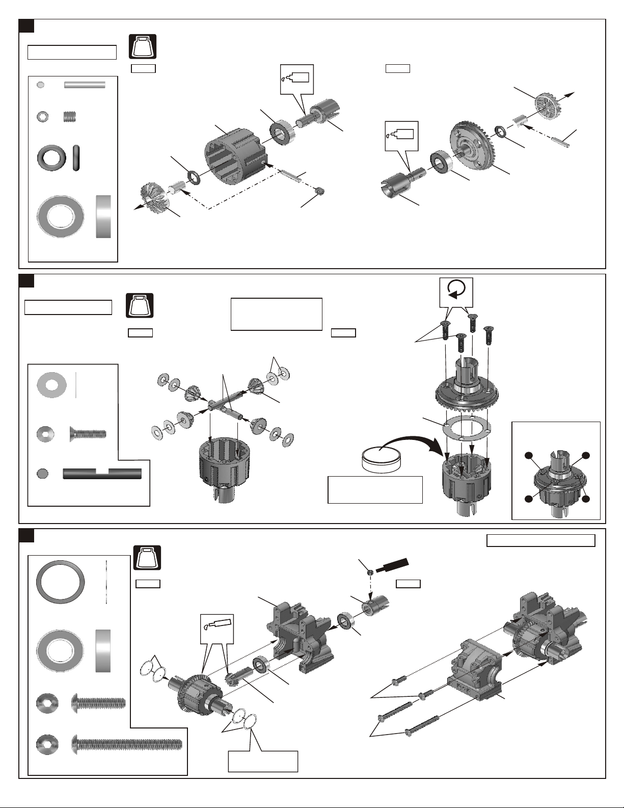
ASSEMBLY OF THE FRONT AND REAR DIFF.
NO.2
Builds two differentials for front
and rear.
40010
2.5x13.8mm Pin
94034
4x4mm
Set Screw
40009
P6 O-Ring
36053
8x16mm Ball Bearing
5
ASSEMBLY OF THE FRONT AND REAR DIFF.
.....x4
.....x2
.....x4
.....x4
BAG
Step 1 Step 2
40538
Diff. Case
40009
P6
O-Ring
40513
Diff. Gear
(Large)
36053
8X16mm
Ball Bearing
Oil
4X4 mm
Set Screw
40010
2.5x13.8mm
Pin
40514
Cap Joint
Oil
40514
Cap Joint
36053
8X16mm
Ball Bearing
40513
Diff. Gear
40517
43T
Large
Bevel Gear
40009
P6
O-Ring
40010
2.5x13.8mm
Pin
Builds two differentials for front
and rear.
30776
4x10mm
Washer
94020
3x12mm
Flat Head
Hex Screw
30773
4mm
Cross Pin
6
ASSEMBLY OF THE FRONT AND REAR GEAR CASE
.....x16
.....x8
.....x4
NO.1
BAG
NO.12
Step 1 Step 2
NB. It is very important to remove
the 30776 washer if the gear
mesh is too tight.
30773
4mm
Cross Pin
30776
4X10mm
Washer
NO.2
NO.4
BAG
NO.5
40024
13x16x0.2mm
Shim
.....x8
Step 1 Step 2
Apply
40024
13X16X0.2 mm
Shim
Grease
40533
Gear Case
40513
Diff. Gear
(Small)
3X12mm
Flat Head
Hex Screw
40011
Diff. Gasket
i
f
f. l
O
iD
*Put the Diff. Oil #100000 for front
and the #50000 for Rear
*Fill the Diff. case to approx. 80%
with the Diff. Oil
94036
5x5mm
Set Screw
40519
Cap Joint
36053
8X16mm
Ball Bearing
Sc wre
Cem
Tighten
Tight the diff screws in this order.
1
4
Builds two gear case for front and rear.
ent
3
2
36053
8x16mm Ball Bearing
94011
4x16mm
Hex Screw
94015
4x35mm
Hex Screw
.....x4
.....x4
.....x4
40024
13X16X0.2mm
Shim
36053
8X16mm
Ball Bearing
40516
13T
Small Bevel Gear
¡¯Adjust t he backl ash
¡@wi t h t he shi ms.
4X16mm
Hex Screw
4X35mm
Hex Screw
40533
Gear Case
2
7
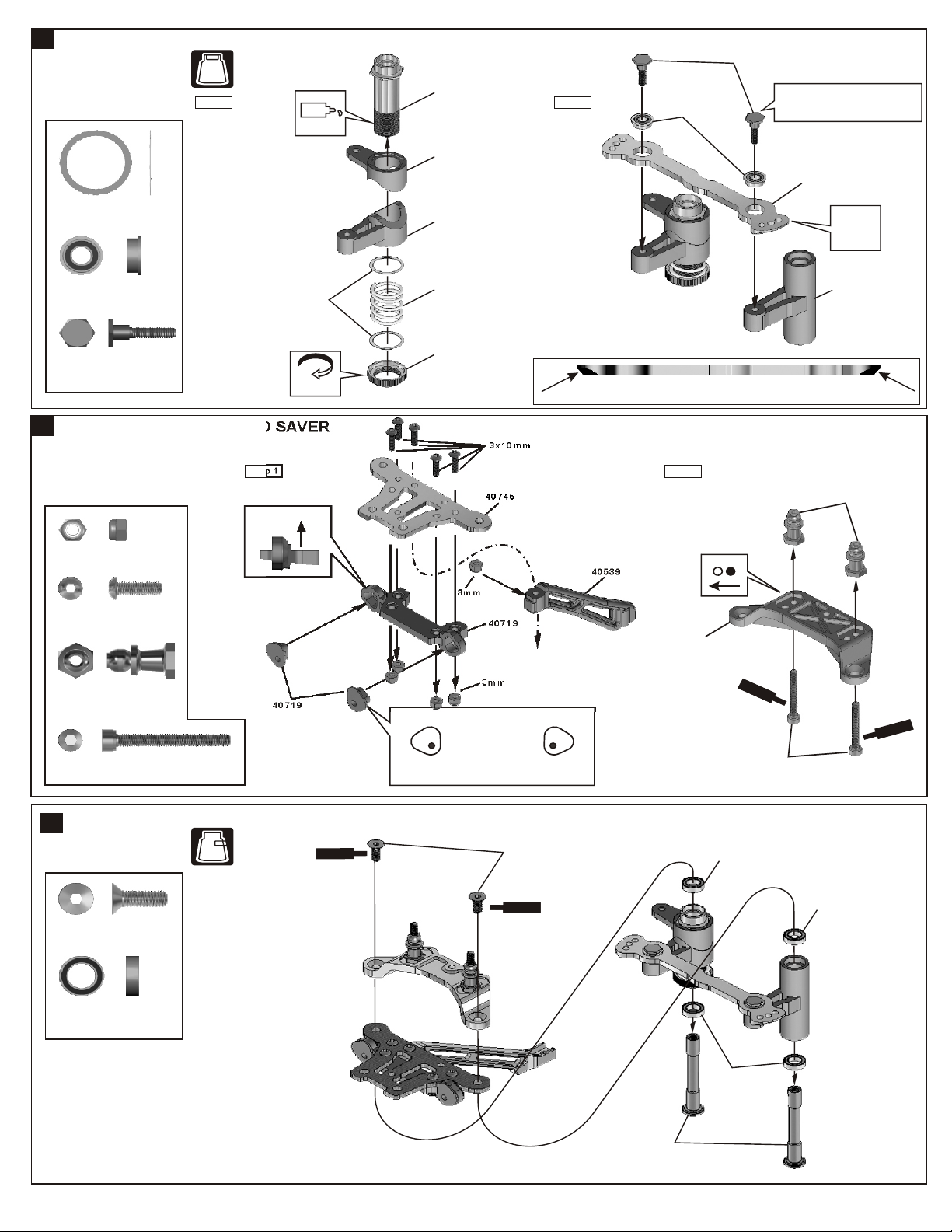
ASSEMBLY OF THE SERVO SAVER
NO.3
BAG
Step 1
40037
Steering Plate
Hex Screw
40563
Servo Saver
Tube(Hard-Coated)
Step 2
40073
4x8mm
Flange Bearing
*Tighten the steering plate hex screw
all way down and then back it off 1/2
turn.
Oil
40539
Servo Saver
Horn
40560
Alum. Servo Saver
Connecting Plate
(Hard-Coated)
40024
13x16x0.2mm
Shim
40073
4x8mm
Flange Bearing
40037
Steering Plate
Hex Screw
8
ASSEMBLY OF THE SERVO SAVER
.....x2
.....x2
.....x2
40024
13X16X0.2mm
Shim
Step 1 Step 2
94041
3mm
Nylon Nut
94003
3x10mm
Hex Screw
.....x5
.....x5
Rotate
Direction
40539
Servo Saver
Horn
40500
Servo Saver
Spring (Black)
40034
Servo Saver
Spring Tension
Adjuster
40745
3mm
3x10mm
40719
* Notice the direction of the servo saver connecting plate.
40539
40719
Ensure
Free
Movement
40539
Servo Saver
Horn
40531
40531
Shock Ball
End Post
90018
3x25mm
Cap Screw
9
ASSEMBLY OF THE SERVO SAVER
94026
4x12mm
Flat Head
Hex Screw
40074
6x10mm
Ball Bearing
.....x2
.....x2
BAG
.....x2
.....x4
40719
NO.3
S
C
cr
m
e nt
3mm
4x12mm
Flat Head
Hex Screw
Sc
ew
r
en
em t
C
Right
40511
Servo Saver
Post
Left
*Set the left and right hand side upper arm
adjuster in the same direction.
w
e
e
Sc w re
C nt
3x25mm
40074
6x10x3mm
Ball Bearing
40074
6x10x3mm
Ball Bearing
eme
40074
6x10x3mm
Ball Bearing
Scre
C
w
t
n
e
em
3

10
ASSEMBLY OF THE STEERING TIE-ROD
NO.3
BAG
40038
7mm Ball
36700
7mm Steering
Ball End
36790
4x46mm
Turnbuckle
36700
7mm Steering
Ball End
40038
7mm Ball
40548
3mm
Nylon Nut(Thin Type)
40126
3X6mm
Flange Washer
40038
7mm Ball
Step 1
.....x2
.....x2
.....x4
1:1
Approx. 29.30 mm
29.30 mm
36700
7mm Steering
Ball End
11
ASSEMBLY OF THE SERVO SAVER AND FRONT UPPER ARMS
.....x4
BAG
NO.3
NO.4
Step 1
4x10mm
Hex Screw
Step 2
40548
3mm
Nylon Nut
(Thin Type)
e Scr
w
eC me
Assembly of the right and left hand side
are the same.
40126
3X6mm
nt
Flange Washer
94021
3x15mm
Flat Head
Hex Screw
Assembly of the right and left hand side
are the same.
94020
3x12mm
Flat Head
Hex Screw
94026
4x12mm
Flat Head
Hex Screw
94009
4x10mm
Hex Screw
40525
3x48.1mm Arm Shaft
.....x2
.....x4
.....x2
.....X2
*Insert the upper arm adjust
into shock stay.
4x12mm
Flat Head
Hex Screw
40533
Front Plate Bad
Front
Step 2
40719
Upper Arm
Adjuster
40716
Caster Angle
Adjuster (2mm)
40716
Front Upper
Arm
40716
Caster Angle
Adjuster
(1mm and 3mm)
40525
3x48.1mm
Arm Shaft
40525
3x48.1mm
Arm Shaft
3x12mm
Flat Head
Hex Screw
40719
Shock Stay
4
Left
*Set the left and right hand side upper
arm adjuster in the same direction.
Right

12
ASSEMBLY OF THE FRONT SHOCK STAY
NO.4
BAG
36742
Shock Cap
Bushing
.....X2
35958
5x8x2.5mm
Ball Bearing
3x16mm
Hex Screw
40719
Shock Mount(A)
40719
Shock Mount(B)
Ensure
Free
Movement
Assembly of the right and left hand side
are the same.
35958
5x8x2.5mm
Ball Bearing
94005
3x16mm
Hex Screw
13
ASSEMBLY OF THE FRONT SHOCKS ONTO SHOCK STAY
94041
3mm
Nylon Nut
94040
3x8mm
Washer
40643
Shock Cap
Washer
.....X4
.....x2
BAG
.....x2
.....x2
.....x2
NO.1
36742
Bushing
3x12mm
Hex Screw
Do Not
Over Thigten
3x8mm
Washer
"L"make are for inside.
3mm
Nylon Nut
40643
Shock Cap
Washer
*Take the shock cap washer
from the shock plastic tree.
Assembly of the right and left hand side
are the same.
94004
3x12mm
Hex Screw
14
13
13
ASSEMBLY OF THE REAR SHOCK STAY AND UPPER ARMS
ASSEMBLY OF THE REAR SHOCK STAY AND UPPER ARMS
36850
36850
7mm
7mm
Ball
Ball
94003
3x10mm
Hex Screw
94010
4x12mm
Hex Screw
.....x2
.....x2
.....x2
.....x2
.....x2
.....x4
.....x4
Step 1
Step 1
3x10mm
3x10mm
4x12mm
4x12mm
40750
Step 2
Step 2
Assembly for both right and left side.
Assembly for both right and left side.
40537
40537
36861
36861
40065
1:1
Approx. 12.5 mm
Approx. 12.5 mm
36850
36850

15
ASSEMBLY OF THE REAR UPPER ARMS
Left
*Set the left and right hand side upper arm
adjuster in the same direction.
94011
4x16mm
Hex Screw
40546
3x42.7mm
Arm Shaft
16
ASSEMBLY OF THE REAR BRACE
94010
4x12mm
Hex Screw
.....x2
.....x2
.....x2
4x16mm
Right
40719
40716(2mm)
40539
40719
4x12mm
40716(1mm)
40546
40719
*Insert the caster angle adjuster
onto arm shaft.
40539
94011
4x16mm
Hex Screw
17
ASSEMBLY OF THE TWO SPEED GEARS
.....x1
BAG
NO.7
Step 1
94036
M5x5mm
Set Screw
35230
8x12mm
Flange Ball Bearing
.....x1
.....x2
Anti-Clockwise
Rotate
Direction
35228
Alum. Nut
Step 2
Rotate
Direction
35219
Alum. Nut
35248
1st Spur Gear
(48T)
35244
2nd Spur Gear
(44T)
35225
1st Spur Gear
Holder
(One-Way)
35234
2nd Spur Gear
Clutch Bell
Clockwise
35230
8x12mm
Flange
Ball Bearing
* Push the flange ballbearing
into clutch bell.
4x16mm
35235
Clutch shoe
Step 3
*Put the clutch shoe carrier to the edge of the groove
on the shaft.
Carrier
40112
2-Speed Shaft
5x5mm
Set Screw
* Place the set screw in
the "D" cut.
t
rew
c
en
S
Cem
6

18
ASSEMBLY OF THE TWO SPEED TRANSMISSION
NO.7
BAG
3x15mm
Hex Screw
35237
Spring
35237
4mm Ball
3mm
Nylon Nut
35237
6X6mm
Set Screw
94036
5X5mm
Set Screw
35237
6X6mm
Set Screw
94041
3mm
Nylon Nut
35237
4mm Ball
94005
3x16mm
Hex Screw
Step 1
.....x2
.....x2
.....x2
.....x2
.....x2
35237
6X6mm
Set Screw
3mm
Nylon Nut
35236
Clutch
Shoe
35237
4mm Ball
35236
Clutch
Shoe
35237
Spring
3x15mm
Hex Screw
*Screw the 3x15mm screw into
the bottom and back off 5 turns.
3x15mm
Screw
3x15mm
Screw
36053
8x16x5mm
Ball Bearing
40120
Brake
Cap Joint
t
w
n
re
e
Sc
Cem
Ensure
Free
Movement
5X4mm
Set Screw
Step 2
1st Gear
Assembly
36053
8x16x5mm
Ball Bearing
40120
Brake
Cap Joint
2nd Gear
Assembly
5X5mm
Set Screw
nt
w Sc
e
r
Ceme
40040
Center Diff.
Mount
40040
Center Diff.
Mount
40512
Center Diff.
Mount Post
Scr
ew
C
e n
met
7
3x3mm
Set Screw
30171
Brake Lever
19
ASSEMBLY OF THE TWO SPEED TRANSMISSION INTO THE CENTER MOUNT
NO.7
BAG
Step 1 Step 2
30212
5x8mm
Flange Bearing
94003
3x10mm
Hex Screw
20
ASSEMBLY OF THE BRAKE AND CENTER DIFF. MOUNT
94033
3x3mm
Set Screw
.....x1
.....x4
.....x1
NO.7
BAG
*Leave a 1.5 mm space
between the two brake pads.
3x10mm
Hex Screw
30212
5x8mm
Flange Bearing
40547
Brake Cam
Do Not
Over Tighten
3x10mm
Hex Screw
40719
Center Diff.
Mount Plate
4x4mm
Set Screw
94034
4x4mm
Set Screw
94011
3x16mm
Hex Screw
.....x2
.....x2
3x15mm
Hex Screw
1.5mm
36659
Brake Pad
36659
Brake Pad
49009
CNC Brake Disk
40714
Center Carry
Handle
*Insert the brake disc into
brake cap joint before assembly.

21
ASSEMBLY OF THE ARM HOLDER ONTO CHASSIS
NO.4
BAG
NO.5
*set the arm holder adjuster to
the same direction.
94027
4x16mm
Flat Head
Hex Screw
.....x8
A A
(Type A)
40748
Chassis
*set the arm holder adjuster to
the same direction.
A
(Type A)
A
40719
Arm Holder
40719
Arm Holder
Adjuster
40719
Arm Holder
(Front/Front)
22
ASSEMBLY OF THE FRONT LOWER ARMS
(Front/Rear)
NO.6
BAG
Step 1
4x10mm
Set Screw
94035
3x8mm
Set Screw
36870
4x10mm
Set Screw
94005
3x16mm
Hex Screw
94006
3x18mm
Hex Screw
.....x2
.....x2
.....x2
.....x4
40719
Stabilizer mount
40719
Stabilizer Balance
Adjuster
3x18mm
Hex Screw
2mm
3x8mm
Set Screw
4x16mm
Flat Head
Hex Screw
8
40717
Front Lower Arm
31308
Stabilizer
*A 3x8mm set screw is use for
thighten or loose stabilizer.
(Left Side)
4x16mm
Flat Head
Hex Screw
40711
4mm Arm Shaft
Step 2
40711
4mm Arm Shaft
40719
Arm Holder
(Rear/Rear)
40719
Arm Holder
Adjuster
40719
Arm Holder
(Rear/Front)
Assembly of the right and left hand side
are the same.
*Keep stabilizer ball in the center. Turn stabilizer
adjuster to adjust the stabilizer to the same angle.
23
ASSEMBLY OF THE REAR LOWER ARMS
NO.6
BAG
4x10mm
Set Screw
Step 1
40719
Stabilizer mount
94035
3x8mm
Set Screw
36870
4x10mm
Set Screw
94005
3x15mm
Hex Screw
94006
3x18mm
Hex Screw
.....x2
.....x2
.....x2
.....x4
40719
Stabilizer Balance
Adjuster
3x18mm
Hex Screw
40719
Stabilizer Balance
3x18mm
Hex Screw
Adjuster
3x8mm
Set Screw
3x8mm
Set Screw
31308
Stabilizer
31308
Stabilizer
40717
Rear Lower Arm
40719
Stabilizer mount
40717
Rear Lower Arm
4x10mm
Set Screw
Step 2
40711
4mm Arm Shaft
2mm
Adjuster
Assembly of the right and left hand side
are the same.
*Keep stabilizer ball in the center. Turn stabilizer
adjuster to adjust the stabilizer to the same angle.
Adjuster
Center
Center

24
ASSEMBLY OF THE FRONT AND REAR GEAR BOX ONTO THE CHASSIS
NO.3
NO.5
BAG
NO.6
Step 1
BAG
Front Gear Box
Assembly
NO.6
4x16mm
Flat Head
Hex Screw
94041
3mm
Nylon Nut
94020
3x12mm
Flat Head
Hex Screw
94026
4x12mm
Flat Head
Hex Screw
94027
4x16mm
Flat Head
Hex Screw
25
ASSEMBLY OF THE FRONT KNUCKLE ARMS
.....x4
.....x4
.....x2
.....x8
Step 1
40718
Ball type
Knuckle Arm(left)
L
94049
2.6x8mm
Cap Screw
.....x8
*Notice the direction of the
plastic washer.
36903
14mm
Steering Ball
4x10mm
Flat Head
Hex Screw
40718
Plastic Washer
3mm
Nylon Nut
3x12mm
Hex Screw
36904
12mm
Alum. Nut
Step 2
4x16mm
3mm
3x12mm
Assembly of the right and left hand side
are the same.
Ensure
Free
Movement
36904
14mm
Alum. Nut
36903
12mm
Steering Ball
26
ASSEMBLY OF THE FRONT KNUCKLE AND FRONT SUSPENSION ARMS
.....x4
.....x4
36903
14mm
Steering Ball
40718
Plastic Washer
36904
12mm
Alum. Nut
Do Not
Over Tighten
NO.3
NO.6
BAG
94041
3mm
Nylon Nut
94034
4X4mm
Set Screw
94021
3x56mm
Flat Head
Hex Screw
36055
2.5x16.8mm Pin
..........X2
..........X2
..........X2
..........X2
Step 1
e
r w
c
e e
S
Cmnt
NO.12
5x4mm
Set Screw
36053
8x16mm
Ball Bearing
40526
Alum
Wheel Hub
36055
2.5x16.8mm
Pin
40521
Universal Joint
(Front)
36053
8x16mm
Ball Bearing
40724
Dust Boot Bushing
Step 2
*Put the drive shaft into
cap joint before assembly.
3mm
Nylon Nut
Ensure
Free
Movement
Assembly of the right and left hand side
are the same.
3x56mm
Flat Head
Hex Screw
40126
3X6mm
Flange Washer
36053
8x16mm Ball Bearing
..........X4
40724
Dust Boot Bushing

27
ASSEMBLY OF THE FRONT PUSH RODS
Assembly for both right and left side.
Step 1 Step 2
30403
6mm Ball
94004
3x12mm
Hex Screw
94007
3x20mm
Hex Screw
28
ASSEMBLY OF THE REAR WHEEL HUB
94036
5x4mm
Set Screw
36055
2.5x16.8mm Pin
36053
8x16mm
Ball Bearing
31307
11mm
Steering Ball
.....x2
.....x2
.....x4
.....x4
.....x4
.....x2
.....x2
40063
Step 1
31304
31307
30403
31305
40712
1:1
Approx. 34mm
31306
30403
40063
Step 2
36082
36053
Do Not
Over Tighten
Ensure
Free
Movement
3x20mm
3x12mm
Assembly for both right and left side.
36055
36053
40526
8x12x1mm
5x4mm
Sr ew
c
eCm ent
29
ASSEMBLY OF THE REAR SUSPENSION ARMS
94041
3mm
Nylon Nut
94008
3x25mm
Hex Screw
.....x2
.....x2
*Insert the drive shaft before assembly.
34028
3x25mm
Assembly for both right and left side.
*When assembling the steering balls into
the arms,leave about one threads for the
rear arm ,and leaveno room for front arm.
(Front)
(Rear)
3mm
2.5mm Allen Wrench

30
ASSEMBLY OF THE REAR SHOCK ABSORBER
94040
3x8mm
Washer
94041
3mm
Nylon Nut
40531
Shock Ball
End Post
.....x2
.....x2
.....x2
3mm
3x8mm
40643
40531
3x25mm
Assembly for both right and left side.
94007
3x20mm
Hex Screw
90018
3x25mm
Cap Screw
31
ASSEMBLY OF THE TWO SPEED TRANSMISSION ONTO THE CHASSIS
94026
4x12mm
Flat Head
Hex Screw
.....x4
.....x2
.....x2
3x20mm
* Insert drive shaft into cap joint before
assembly two speed onto chassis.
40749
40749
32
ASSEMBLY OF THE CLUTCH
NO.10
BAG
* Only use the 10091 pilot shaft for threaded crank
shaft engine.
tC me
crew
S
e n
Threaded
Crank Shaft
10330
Tapper Corn
Tighten
40573
3 Pin Flywheel
(35mm)
10091
Pilot Shaft
(Not Included)
40573
3 Pin Flywheel
(35mm)
10098
SG Clutch Nut
Step 1
c
C ee
m
10330
7mml
Tapper Corn
S
c
r w
e
C n
e
me t
SG Type
re S w
nt
*Fit the flywheel using a pair of the plier
and cross wrench.
Crank Shaft Engine
Step 2
4x10mm
*Place the clutch shoes with the clutch
springs over the 3 pins of the flywheel.
*Using a phillips screw driver or needle
nose pliers and bend the small end lf the
clutch spring behind the pilot shaft
#174D or #180D than press down.
10101
Clutch Spring
10010
Clutch Shoes
Engine rotation direction.

33
ASSEMBLY OF THE CLUTCH
BAG
NO.10
35240
16T-1st
Clutch Gear
NO.10
Step 1
Step 2
10099
3x7mm
Washer
10099
5x8x0.3mm
Washer
35958
5x8mm
Ball Bearing
34110
5x10x4mm
Ball Bearing
10099
3x5mm
Cap Screw
34
ASSEMBLY OF THE MANIFOLD AND MUFFLER
.....x1
.....x3
.....x1
.....x1
.....x1
35255
20T-2nd
Clutch Gear
BAG
Step 1 Step 2
94038
3x12mm
Cap Screw
.....x4
C t
em
Sc w
Step 3
34110
5x10x4mm
35242
S
Clutch Bell
Cem
c
r
ew
e t
n
35958
5x8mm
Ball Bearing
Sc
C
r
e
mne
w
e
t
10099
3x7mm
10099
3x5mm
Cap Screw
re
en
3x12mm
Cap Screw
cre
S w
t
en
Cem
Washer
Ball Bearing
Not
Included
10099
5x8x0.3mm
Washer
*Adjust the backlash
with the washer.
Manifold(Option)
97501
1/8 Silicone
Seal(Option)
Not
Included
40574
Low Profile
Engine Mount
35
ASSEMBLY OF THE ENGINE ONTO THE CHASSIS
3x12mm
Step 1
94038
3x12mm
Cap Screw
10114
5mm
Engine Mount Screw
.....x4
.....x4
3x5mm
Spring Washer
Step 2
3x5mm
Spring Washer
*The muffler and manifold may not be
included in some kit.
Muffler(Option)
Note book Paper.
*Use note book paper to set gear backlash
between spur gear and clutch bell gear,
applying pressure while retightening the
engine.
*If the space is not correct the spur gear
will be damaged.
Not
Included
97501
1/8 Spring
Not
Included
40574
10114
r w e
Sc
ment
e
C

37
ASSEMBLY OF THE MANIFOLD ONTO THE ENGINE
94034
4x4mm
Set Screw
94036
5x4mm
Set Screw
Step 1 Step 2
.....x1
.....x1
*The muffler and manifold may
not included from different kit.
1/8 Spring(Option)
94026
4x12mm
Flat Head
Hex Screw
.....x1
Not
Included
1/8 Silicone
Seal(Option)
Muffler(Option)
39
ASSEMBLY OF THE FUEL TANK ONTO THE CHASSIS
94019
3x10mm
Flat Head
Hex Screw
.....x2
BAG
NO.3
NO.11
Step 1
40543
Fuel Tank
3x10mm
Hex Screw
Manifold(Option)
12
Do Not
Over Tighten
Scre
Cem
w
nte
4x10mm
Step 2
41050
4x4mm
c
e
n
e t
Srw
m
Ce
5x4mm
10052
10069
10120
94003
3x10mm
Hex Screw
40
40
ASSEMBLY OF THE RADIO TRAY
94040
3x8mm
Washer
94002
3X8mm
Hex Screw
94005
3x16mm
Hex Screw
40709
Alum.
Radio Tray
.....x2
BAG
Step 1
3x8mm
Hex Screw
.....X8
.....X7
.....X8
NO.9
S
Ceme
40715
Alum. Throttle
Pivot Post
cr
e
w
nt
40539
Fuel Tank
Post
40541
Radio Tray
Post
( Plastic )
3x8mm
Hex Screw
Pressure Nipple
3x8mm
Washer
3x16mm
Hex Screw
Put the protector rubber
onto your servo.
3x16mm
Hex Screw
Step 2
3x8mm
Washer
Throttle Servo
Steering Servo
34026
Servo Washer
34026
Servo Mount
34026
Servo Washer
34026
Servo Mount
Step 3
3x10mm
Flat Head Hex
Screw
Do Not
Over Tighten
3x8mm
Hex Screw

41
ASSEMBLY OF THE RADIO TRAY AND RECEIVER BOX
NO.9
BAG
2X8mm
Screw
40541
Receiver Box
*Connect the switch
wire to receiver.
Switch
2X8mm
Screw
94002
3X8mm
Hex Screw
Step 1 Step 2
.....X4
.....X2
*Use the screw provided
with your switch
10280
Switch Cover
40541
Switch holder
40580
Protective Foam
for Receiver Box
40541
Receiver Box
Cover
37410
Clips
40541
Receiver Box
Cover
Antenna
30560
Antenna Pipe
40642
Antenna Pipe
Fixing Nut
*Put the servo wire into
receiver box and connect to
receiver.
*Use the original battery case
or rechargeable hump pack
battery.
*Connect battery wire to switch.
Battery
3X8mm
Hex Screw
40541
Receiver Box
42
ASSEMBLY OF THE THROTTLE LINKAGE
3x3mm
Set Screw
30531
Throttle
Spring
37360
4mm
Ball & Socket
30800
2.6x6mm
Washer
94033
3x3mm
Set Screw
94003
3x10mm
Hex Screw
94050
2.6x10mm
Cap Screw
.....x3
.....x3
.....x1
.....x1
BAG
NO.9
Step 1
3x3mm
Set Screw
10300
Alum
Stopper
3x10mm
Hex Screw
30800
Adjust Mount
Ensure
Free
Movement
40719
Servo Horn
40580
Protective Foam
for Receiver Box
10300
Alum
Stopper
2.6x10mm
Cap Screw
30800
Adjust Mount
2.6x6mm
Washer
Tighten
3x3mm
Set Screw
30800
2mm
Adjust nut
Completely Finished
30172
2X68mm
Brake Rod
Receiver
30800
Throttle
Ball End
Tighten
Step 2
Servo Wire
3x5mm
Hex Screw
3x8mm
Washer
35958
5x8x2.5mm
Ball Bearing
43
ASSEMBLY OF THE THROTTLE LINKAGE INTO SERVO
Cut off the servo saver as shown.
37650
4mm
Ball End(Short)
3x8mm
Set Screw
37650
4mm
Ball End(Long)
*Use the screw provided
with your servo.
94035
3x8mm
Set Screw
30403
6mm Ball End
NO.9
BAG
.....x1
.....x2
*Ensure that servo gears are centered before attaching
the servo horns. The best way to accomplish this is by
connecting the servos to the radio system and setting
the trim to the center.
10765
Servo Horn
37360
4mm
Ball & Socket
10765
Servo Horn
Adapter
A
A'
Sanwa/Airtronics
S J F
* Choose the right servo horn adapter for your servo.
JR
Futaba
HiTech
H
Parallel

44
ASSEMBLY OF THE STEERING ROD AND RADIO TRAY ONTO THE CHASSIS
*Snap on.
NO.9
BAG
30403
6mm Ball End
94019
3x10mm
Flat Head
Hex Screw
94004
3X12mm
Hex Screw
30401
Plastic Ball End
45
ASSEMBLY OF THE FRONT BUMPER
.....x1
.....x8
.....x1
.....x2
*Use the screw provided
with your servo.
NO.8
BAG
Step 1
30403
6mm
Ball
10765
Servo Horn
10765
Servo Horn
Adapter
3X12mm
Hex Screw
40713
3x64mm
Turnbuckle
1:1
Approx. 49 mm
¬ù 49mm
40721
Front Bumper
Post
30403
6mm
Ball
30401
Plastic Ball End
Step 2
3x10mm
Flat Head
Hex Screw
3x10mm
Flat Head
Hex Screw
3x3mm
Set Screw
3X12mm
Hex Screw
10300
Alum
Stopper
94026
4x12mm
Flat Head
Hex Screw
94020
3x12mm
Flat Head
Hex Screw
94042
4mm
Nylon Nut
46
ASSEMBLY OF THE FRONT BUMPER
.....x3
.....x2
.....x3
BAG
NO.8
Step 1
36870
4x10mm
Set Screw
94026
4x12mm
Flat Head
Hex Screw
.....x2
.....x2
4mm
Nylon Nut
40721
Front Bumper
Tighten
3x12mm
Flat Head
Hex Screw
4x10mm
Set Screw
40721
Front Bumper
Top Plate
40721
Front Bumper
Post
Step 2
40117
Body Post
Tighten
4x12mm
Flat Head
Hex Screw
40720
Body Post
40117
Body Post
Completely Finished
Approx. 4 mm
ャ 4mm
* The 4x10mm set screw
is used to adjust down stop.
Tighten
4x12mm
Flat Head
Hex Screw
31159
Body Clip
Tighten

47
ASSEMBLY OF THE FRONT AND REAR BUMPER
NO.8
BAG
3x12mm
Flat Head
Hex Screw
94042
4mm
Nylon Nut
94009
4x10mm
Hex Screw
.....x2
.....x2
40725
Foam Bumper
4x10mm
Hex Screw
40721
4mm
40721
94020
3x12mm
Flat Head
Hex Screw
94026
4x12mm
Flat Head
Hex Screw
ASSEMBLY OF THE BOOY AND PAINTNG.
48
.....x4
.....x2
Tighten
Cut out the body as shown.
Cut Out
Before cutting and making holes on the body,
put the unpainted body on the chassis
to confirm the mounting position and
location for holes and cutouts.
31138
Body(Option)
Tighten
3x12mm
Use a neutral detergent to
remove any dirt and oil.
Mask the windows from
the inside with masking tape.
4x12mm
Body Reamer
(Not included.)
Making two holes on the front and
two holes on the rear for body posts.
9mm
9mm
Paint the body with
polycarbonate spray paints.
Spray Paint

ASSEMBLY OF THE ONTO FRONT KNUCKLE AND REAR HUB
49
Step 1 Step 2
Cut Out
50
ASSEMBLY OF THE AIR FILTER
NO.11
BAG
*Apply filter oil to the
foam before use.
Side Plate
Take off the doubleside
paper before assembly.
Doubleside
Tape
Nylon Screw
Do Not
Over Tighten
Doubleside
Tape
Nylon Nut
Side Plate
38400
Air Filter
Nylon Strap
*Notice the direction and make two lift and
right hand side tires are the same.
*Check the rotation direction before gluing.
51
ASSEMBLY OF THE TIRES AND WHEELS
*Notice the direction of the tires. Make two
(Left Hand Side)
*Notice the direction
of the tires.
86052
Tire
the same for the left and 2 for the right.
Check the rotation direction before gluing.
Contact
Adhesive
Contact
Adhesive
Connect to
fuel tank.
Connect to fuel tank
pressure nipple.
(Right Hand Side)
*Notice the direction
of the tires.
Contact
Adhesive
Contact
Adhesive
Connect to carburetor.
10179
Fuel Tube
Connect to
pressure nipple.
86059
Inner Sponge
(WidE)
86059
Inner Sponge
(Narrow)
86023
Wheel
*Pull back the tire bead slightly and spot glue in four spots as
shown. When dry, glue the rest of the wheel between the spots.
Repeat the procedure on the other side of the wheel until fully
glued.
IN
STAN
T
GLUE

52
ASSEMBLY OF THE WHEELS ONTO THE FRONT KNUCKLE AND REAR HUB
Assembly for both right and left side.
40550
Wheel Nut
53
MOUNTING BODY
Step 1
40550
.....x4
*Notice the direction of the tire pattern.
31159
40550
40550
*Tire and Wheel assembly.
40550
31159

54
STARTING OF THE ENGINE
How to start the engine:
1. Turn on transmitter and then receiver.
2. Fill fuel tank with fuel bottle.
3. Connect 1.2V glow plug .
4. Start engine with a 12V starter.
( Notice the direction of the starter.)
5. After the engine has started, remove the
1.2V glow plug .
* Follow the engine manufacturer instruction
manuals regarding engine set-up, carburetor
and maintenance.
*To start the car, attach a glow plug igniter
to the glow plug, and use either a 12V electric
starter or starter box applied to the flywheel
exposed through the chassis.
igniter
igniter
1.2V
A 12V Starter Box
( Not Included)
10250 - Starter Box 1/8 scale
On/Off-Road.
Glow Plug (Not Included)
51007
Normal Plug
51006
Turbo Plug
*There are 2 types of glow plugs
available"NORMAL" or "Turbo"
depending on the type of the engine.
1.2V Glow Plug Igniter and
Charger (Not Included)
10215 - Glow Heater, Extra Long
W/Charger.
1.2V
ADJUSTING THE SHIFT POINT
Adjust the engine before adjusting the clutch shift timing.
Adjust the engine as per engine instruction manual.
3x15mm
Hex Screw
6x6mm
Set Screw
3x15mm
Hex Screw
2mm
Allen Wrench
Clockwise
(Tighten)
Anti-clockwise
(Loosen)
*Applied to the flywheel
exposed through the
chassis.
Starter Box
(Not Included)
SHIFT UP TIMING ADJUSTMENT
1. Once the engine adjustments have been completed, proceed to the
adjustment of the clutch shoe shift timing.
(Using a 2mm allen wrench to adjust the clutch shoe on either side.)
Note: Clockwise--------Shift timing will become later.
Counterclockwise---Shift timing will become quicker.
2. Adjust the clutch shift timing for your track conditions.
As you tighten (Clockwise) the 3x15mm screw, the shift timing will
become slower.
As you loosen (Counterclockwise ) the 3x15mm screw, the shift timing
will become quicker.
3. Set the shift timing to the track conditions while the car is running.
2 SPEED GEAR RATION COMBINATIONS
2 speed transmission allows the car to have more punch out of the
corners and higher top speed. We offer many different pinion and
spur gear combinations which can be used for different tracks.
Spur Gear
49T/45T
48T/44T
Clutch Gear (4 tooth different)
15T-19T
16T-20T
17T-21T
Torque
Speed
21

SETTING GUIDE
FRONT TOE-IN AND TOE-OUT SETTING
NEUTRAL POSITION
TOE-IN
TOE-OUT
REAR TOE-IN
TOE-OUT
Steering Rod
REAR TOE-IN
2.5mm Allen
Wrench
Use a 2.5mm allen wrench to adjust toe-in for front and rear.
Adjust the length of the front steering rod to change the toe angle.
(Front)
Making the steering rod longer will make the front tires become
toe-in.
Response will be slower and will over steer.
Making the steering rod shorter will make the front tires become
toe-out.
Response will be quicker and will under steer.
We recommended adjusting the front toe-out to 1.5 degrees.
(Rear)
Adjust the length of the rear hub (12mm ball/rear) to change
the toe angle.
Making the 12mm ball longer will make the rear tires toe-in.
Response will be under steer.
Making the 12mm ball shorter will make the rear tires toe-out.
Response will be over steer.
We recommended adjusting the rear toe-in to 2 degrees.
FRONT AND REAR CAMBER ANGLE SETTING
Note: Place the model car on a flat surface. Raise the chassis to it's maximum clearance
before the wheels leave the ground.
Adjust the length of the front and rear upper arms so that the wheels are right angles to the
ground.
(FRONT)
+
Positive
The front camber adjustment can be made by moving the 14mm
steering ball at the front upper arms on knuckles, clockwise or
anticlockwise.
We suggest using 1.5 degress of negative camber for the front.
-
Negative
-
+
+
Positive
Adjust the length of the turnbuckle on
can be change the rear camber.
We suggest using 2 degress of negative camber for the rear.
FRONT AND REAR SHOCK ANGLE SETTING
(FRONT)
Soft
Firm
1
2
-
Negative
(REAR)
the rear upper arms
(REAR)
*Use 2.5mm hex wrench
to adjust upper arm ball
in front.
Turnbuckle
Soft
-
1 2 3 4
+
Firm
Firm front suspension, less steering.
Soft front suspension, more steering.
Soft
12
Firm
Firm rear suspension, over steering.
Soft rear suspension, under steering.
Soft
12
Firm

OFNA Descri ption
RETAI L
OFNA Description
RETAIL
10010
3 Shoe Clutch carbon 13.95 40065 Rear Upper Ball End
4.95
10040
3 Pin Flywheel .21 Corn Type 14.95 40073 Bearing, 4x8 Flange
12.95
10052 Spring M uffler Stay 4.95 40074 6x10 Ball Bearing
17.95
10069 Exhaust Connector 6.95
40090
Shock Repair Kit 7.95
10098 Pilot Shaft, SG Type 4.95 40112 2-Speed Shaft
9.95
10101 Clutch Spring 4.95 40117 1/8 Truck Body Mount
10.95
10114
Engine Mount Screw , 5mm Hex
7.95 40120 8m m Cap Joint for Brake
11.95
10120
Manifold Spring 4.95 40126 3x6x2.5 Flange W asher
3.95
10179 Fuel Tube (45cm) 1.95 40500 Servo Saver Spring (Black)
3.95
10185 Silicone Joint Tube Black 4.95 40511 Servo Saver Post 6.95
10270 Fuel Tube Clips 3.95 40512 Center Diff. Mount Post 13.95
10282 Switch Cover, Black 3.95 40513 Diff. Gear (small & large )
16.95
10300
Alum . Stopper 4.95 40514 Cap Joint for D iff. 13.95
10330 Cone, 7mm Brass Tapper 2.95 40516 Steel Bevel Gear 13T (Sm all) 14.95
10765
Universal Servo Horn 8.95 40517 Steel Bevel Gear 43T (Large) 38.95
30171 Brake Lever
1.95 40519
Cap Joint 9.95
30172 Brake Rod
1.50 40521
Universal Joint, Front 44.95
30212 5x8x2.5 Frange Bearing 5.95
40522
Rear Drive Shaft 19.95
30401 6m m Ball E nd (Plastic)
2.95 40525
Rear Lower Arm Shaft (3x48.1m m ) 6.95
30401
Plastic Parts Set for Dam per 2.95
40526
17m m W heel Hub 11.95
30403 6m m Ball & Socket
4.95 40531
Shock Ball End Post/one- piece/Top 9.95
30531 Throttle Spring
2.95 40533
Gear Case 11.95
30560 Antenna Pipe
2.95 40537
Front U pper Arms 6.95
30773 4mm Cross Pin
3.95 40538
Diff. Case (F&R) 9.95
30776 4x10x0.2 W asher
1.95
40539 Servo Saver & Center Bracer 11.95
30800 2m m Brake Adjust N ut
6.95 40541
Receiver Box 14.95
30800 Throttle Linkage Plastic 6.95
40543
Fuel Tank 16.95
31159
Body Clips 4.95
40546
Front Arm Shaft 3x42.7mm 11.95
31304
Rear Hub (Ball Type) 10.95 40547 Brake Cam 8.95
31305
Plastic W asher for Ball 8.95 40548 M 3 Nylon Nut (Thin Type) 1.95
31306
12m m Alum . Hex Screw 8.95 40549 M uffler Stay 4.95
31307
11m m Ball & Screw 8.95
40550
17m m W heel Nut 4.95
31308
Stablizer (Steel) (L&R) 10.95 40560 Servo Saver Connecting Plate 12.50
31991
Manifold, 21 W /Spring, Polished 25.95 40563 Alum . Servo Saver T ube 9.95
31994
Pipe, 9.5m m D M -1 RT R Polished 54.95 40568 Graphite Front Plate 31.95
34026 Servo Fixing (Lay dow n) 7.95 40580 Protect Foam for Receiver Box 1.95
34028 Dog Bone, 100mm , ULTRA X-1 15.95 40633
Shock Cap, 13m m 18.95
34110 Ball B earing 5X10X 4
6.95 40634
Shock Spring Adjuster 9.95
34303 DM1-SPEC PRO PARTS LIST
35219
Alum. Nut (clockwise) 2.95
40635
Shock Shaft Dust Covers 5.95
35225
1st Spur Gear Holder (one-way)
26.95
40636
15x1 O-Ring 3.95
35228 Alum. Nut (anti-clockwise) 2.95 40637 Dust Felt for Shock Absorber 1.95
35230 8 x 12 Flange Bearing 12.95 40638 Shock Piston, 13mm 7.95
35234
2nd Spur Gear Clutch Bell 24.95 40640 Shock Pressure Top, Orange 5.95
35235
Clutcn Shoe Carrier 5.95
40642
Antenna Pipe Fixing Nut 2.95
35236
Clutch Shoe 14.95 40643 Plastic Shock Parts Set 9.95
35237
Spri ng 9.95 40674 Engine M ount Tall For Pullstart 18.95
35237
4mm Ball 9.95
40694
CNC 7075 Chassis Brace, F&R 59.95
35237
6x6mm Set Screw 9.95
40708
Chassis 6061 DM1 RTR 89.95
35240
Clutch G ear (1st) 16T 11.95
40709
Radio Tray Alum. DM1 RTR 12.95
35242
Clutch Bell 24.95 40710 Center Drive Shaft 120mm 19.95
35244 44T 2nd Spur Gear 7.95 40711 4x90mm Arm Shaft 7.95
35248
48T 1st Spur Gear 7.95 40712 3.5x48mm Turnbuckle
9.95
35255
Clutch G ear (2nd) 20T 11.95 40713 3x64mm Turnbuckle
9.95
35958 5x8x2.5 Ball Bearing 3.95 40714 Center Handle Bar 3.95
36053 8x16 Ball Bearing 12.95 40715 Throttle Connecting Alum. Post 7.95
36055 2.5x17 Pins
3.95 40716 Rear Upper Arms
9.95
36660 Brake Pads, 4PCS. 3.95
40717 Front & Rear Lower Arms
19.95
36661 Brake Pad W ashers, 4PCS. 3.95
40718 Ball Type Knuckle Arms (L&R)
19.95
36700 Steering 7mm Ball
6.95
40719 Arm Holder Plastic
15.95
36742 Servo Saver Bushing
1.95
40720
Body Side Bum per
9.95
36790 4x46 Turnbuckle
10.95
40721 Front & Rear Bum per
19.95
36850
7mm Ball 3.95
40722 Exhaust Connecter 7.95
36861 5x35 Turnbuckle
6.95
40723 Dust Proof Cover 7.95
36903 Steering Ball 14mm
7.95
40724 Rubber Bushing for Hex Screw
4.95
36904 14mm Alum. Nut
9.95
40725 Foam Bum per 14.95
37360 4mm Ball & Socket
4.95
40731 CNC Alum Shock Stay, F
39.95
37410 Body Pin (S) 3.95 40734 Wing & W ing Stay Unit 12.95
37650 4m m P lastic B a ll Joint
6.95
40735 Real Muffler & Back Mirror 14.95
38400
1/10 Air Filter 9.95
40736
DM -1 Shock Shaft 7.95
40009 P-6 O -R ing
2.95
40737 Shock Body, 13mm 24.95
40010 2.5x13.8 pin
2.95
40738 DM -1 Shock Spring Front (Red), Soft 14.95
40011 Diff. Gas kets
3.95
40745 Alum. Front Plate Black 7.95
40024 Diff Bevel Gear Shim 13x16x0.2mm
2.95
40746 Alum. Servo Saver C nt. Plate Black 9.95
40034 Alum. Servo Saver Ring Adjuster
5.95 40748 CHASSIS, 6061 DM1 SPEC 99.95
40037 Steering Plate Hex Screws
5.95 40749 CENTER DR SHFT DM1S 88.5/104mm 19.95
40038
7m m B alls (B lack ) 9.95 40750 SHOCK TOWER RR ALUM DM1 SPEC 14.95
40040 Center Diff Mount (plastic)
4.95 40751 SPRINGS, REAR RED DM1 SPEC 9.95
40042 Brake Discs, Steel 4Pcs.
10.95 86023
1/8 Mesh W heels (Black) 19.95
40044 Spring, Brake Seperators, 8 Pcs.
5.95
86052 1/8 Radial Tire
19.95
40060 M2.5 Nylon Nut
4.95 86059
GTP Inner Sponge (L&S) 9.95


OWNER’S REGISTRATION CARD
OFNA Racing congratulates you on your purchase of our fine OFNA Product. With proper maintenance and handling this kit will provide many hours of enjoyment.
The registration card should be filled out and mailed to OFNA Racing within 10 days of purchase date.
In the event that the kit is incomplete or component parts are broken due to error in manufacturer, contact your
dealer from which you purchased the kit for replacement part or call OFNA at (949) 586-2910 for your nearest dealer
location. Other items such as radio and engine other covered by individual warranties.
IMPORTANT!
Please print or type, filling in the information listed below and mail immediately
MAIL TO:
OFNA RACING
7 VANDERBILT
IRVINE, CA. 92618
TEL: (949) 586-2910
Write in Your Model Name and Part Number
REGISTRATION CARD
RACER’S NAME TEL:( )
ADDRESS
CITY STATE ZIP
DEALER’S NAME TEL: ( )
ADDRESS
CITY STATE ZIP
OFNA
7 Vanderbilt
Irvine, Ca. 92618
 Loading...