

OFNA Racing DM-1 RTR User Manual
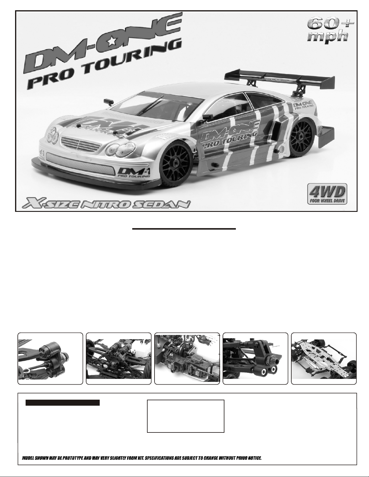
RTR
INSTRUCTION MANUAL
Features:
*High impact large front bumper and foam bumper.
*CNC machined steel transmission bevel gears.
*High Impact plastic front shock mount.
*High Impact plastic rear shock mount with heat sink.
*Low C. G. lay-down steering servo and throttle servo mount.
*Front and rear push rod suspension design.
*Threaded lay-down 13mm big bore shocks for front and rear.
*Adjustable ackerman steering geometry design.
*Aluminum front plate.
*Aluminum low centre of gravity radio tray.
*Front pivot ball suspension with dust boot covers.
*Rear pivot ball uprights for quick geometry changes.
*Spring steel universal joints for front and rear.
*Adjustable blade type sway bar for front and rear.
*Adjustable down-stop and up-stop suspension design.
*High Impact plastic chassis brace.
*Quick release centre differential mount design.
*Convenient carry handle In the centre of the car.
*Changeable roll centre design for front and rear suspension.
*Machined steel discs brake.
*Shoe type 2 speed transmission.
*CNC machined clutch bell with screw-on changeable gears.
*CNC machined 6065 aluminium, milled out slim line chassis.
*Secure transponder mount.
*High flow air filter for maximum engine protection.
*Side body mounts and body protector.
*Rear air flow diffuser creates more down force.
*Exhaust deflector design to protect the inside of the body.
*Chrome exhaust pipe detail parts.
*High grip radial tires on 17mm hex wheels.
*Choice of different body designs.
ADDITIONAL PARTS NEEDED
* Batteries 8 AA for Radio
* Receiver Batteries (10202 Hump Pack)
* Model Fuel 20% Nitro
* CA Glue
* Hobby Knife
THIS IS NOT A TOY !
This kit is extremely fast, and can easily
go over 40mph and can seriously injured
someone. If you are under 18years of age
have and adult supervision.
DEC 3 2007

MUST READ THIS BEFORE RUNNING
Running a nitro kit is fun and easy, but to make this a safe • Clean oil and dirt from chassis with a degreaser.
and good experience you must observe a few rules. This
kit is extremely fast, easily over 40MPH, and can seriously
injure someone if you are not careful.
Precautions
• This kit is not a toy. Always run car with a second
person as a spotter and pitman.
Where to run car?
• Any running area you choose must be dry. Do not run
car near any water or wet dirt.
• Do not run on public streets. It is very easy to have the
car run over or damaged by hitting the curb.
• Do not operate car in tight confined places. The car is
very fast and will easily hit something.
• Do not run near people or animals.
and will too easily hit someone.
• Due noise, you will want to consider the surrounding
area when operating the car.
• Do not operate the car at night. You will not be able to
drive it without hitting something.
• Do not operate the car indoors. Engine exhaust is not
healthy.
Glow Fuel
• Glow fuel is poisonous!
• Glow fuel is flammable! label for additional precautions.
• Do not leave in fuel bottle with lid off at any time.
• Do not use any fuel other than glow fuel in this engine. • Car Fuel tank - Never store fuel in car tank, it will ruin the
First Time Starting the Engine
Caution! When starting engine make sure the following is
observed.
• Set engine Master needle to 3 turns (rich setting) • DAMAGE DUE TO CAR RUN AWAY IS NOT A
• Do not do this alone, get an experienced friend to help at
first.
• Fill fuel tank, try not to spill fuel. Do not spill fuel on
receiver
• Hold car off the ground, so it will not runaway when first
starts
• Turn on Radio and check the linkage before starting
engine.
• Turn on car receiver battery switch.
• Always have an air filter on the carburetor to keep dirt
out.
The car is very fast
• Hot Parts - The pipe, manifold, engine and head are very
hot and will cause burns.
• Rotating Parts - Keep hands away from the drive train,
wheels, and engine when engine is running.
• Radio - Check batteries life before running the car. If
radio does not have full control of the car with steering
and/or throttle/brake do not run until corrected. Failure to
correct this will result in possible injury and damage to the
car or property.
• Glow fuel - Do not leave the glow fuel unattended with the
Lid off. Fuel contains Methanol and Nitro Methane and is
flammable and poisonous.
Store fuel in cool ventilated location. Refer the glow fuel
engine if left in tank.
• Always turn off the car BEFORE turning off radio.
WARRANTY ISSUE.
IF YOU DO NOT BREAK-IN ENGINE
CORRECTLY, MAINLY AT LOW RPM,
YOU WILL BREAK THE CONNECTING
ROD!
FAILURE TO NOT READ AND
Engine Break-in
• See Engine Page.
Emergency Stopping Engine When Running
• Remove air filter and cover carb. intake.
• Squeeze fuel line and hold until engine stops.
• With a rag, cover exhaust outlet.
Storing Car After Running
• Remove fuel from tank and fuel lines
• Turn off radio in car
• Put a few drops of after run in engine to keep it from
rusting.
FOLLOW BREAK-IN ENGINE
INSTRUCTIONS WILL VOID
WARRANTY!
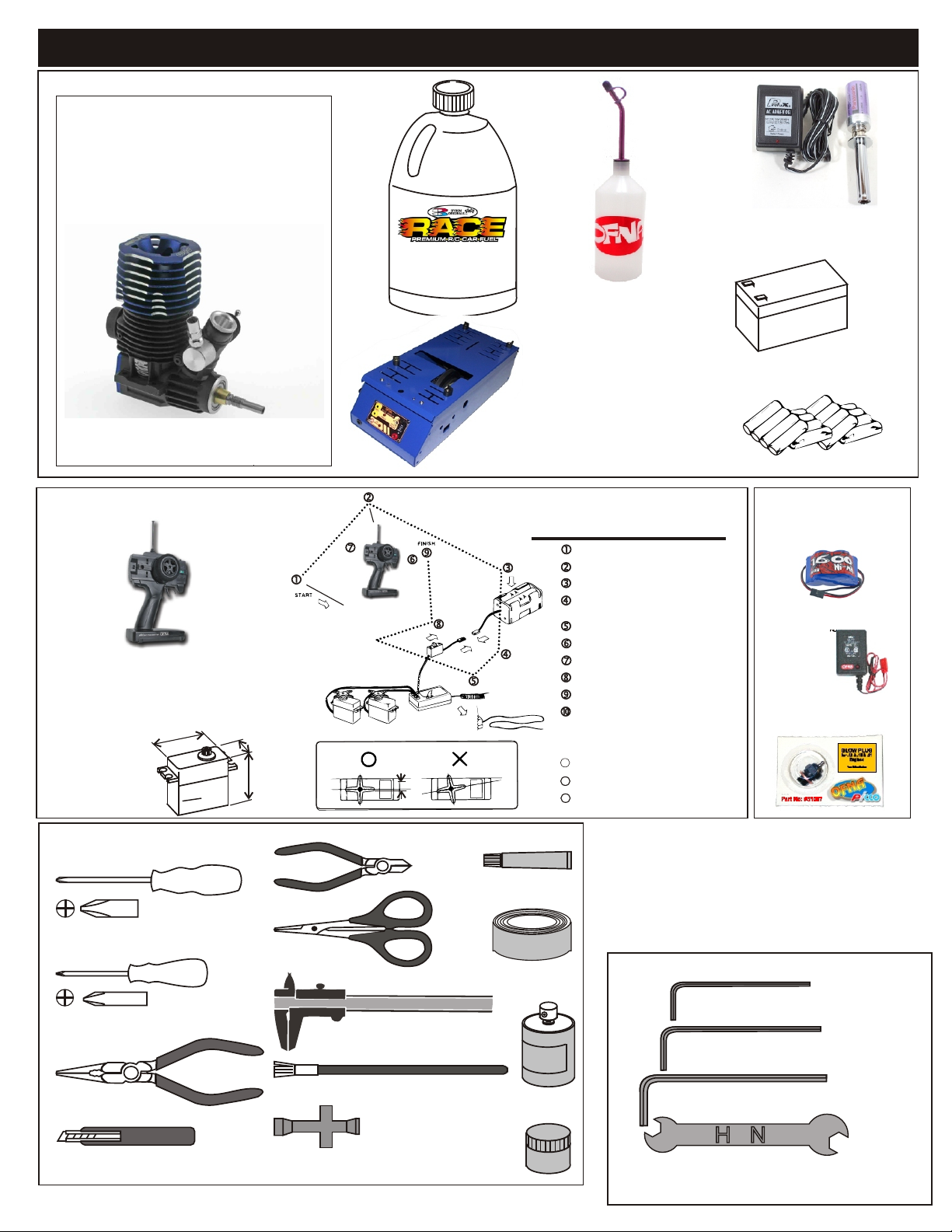
THINGS NEED BESIDES THE KIT
3.5 cc (21 Class) ENGINE
REAR EXHAUST
OFNA/Picco
P-9R EVO
#51219
REQUIRED FOR OPERATION
Glow Fuel
20%
Bottle’s with spout
# 10160 - large 500cc
# 10161 - large 500 ccAuto Stop
# 10162 - small 250cc
# 10164 - CNC spout 500CC
# 10167 - CNC spout 800CC
Glow Plug Long Heat with Battery & Charger
# 10215....$27.95
(please note OFNA Glow Heats available)
Note: Pro kit does not include engine!
RADIO CONTROL UNIT
Note: Carefully read the instruction manual of your
2 channel radio controller before using.
SUITABLE SERVO SIZE
m
m
1
mm-4
36
15mm - 21mm
29mm - 42mm
Off-Road Starter Box, 12V motor
# 10250 - 1/8 scale Starter Box
# 10253 - 1/8 scale Starter Box w/ Panel
Off-Road Starter Box, two 550 motors
# 10248 - 1/8 scale Starter Box
# 10249 - 1/8 scale Starter Box,RTR
Optional Parts
# 92571 - Power Panel Glow Heater
# 92572 - Cable for Glow Plug
Radio must be set at neutral position
before installing in the kit.
SEQUENCE TO SET NEUTRAL
Install AA batteries in Radio.
Extend the antenna.(Transmitter)
Install batteries into Car receiver .
After installing the battery, connect the
battery box.
Extend the antenna. (Receiver)
Set the trim-lever at center.
Turn on the switch. (Transmitter)
Turn on the switch. (Receiver)
Make sure the servos are in command.
When the operation stick is in neutral,
servo horns must be in neutral as will.
*Adjustment can be made by re installing the servo horn.
Turn off the switch. (Receiver)
111111
Turn off the switch. (Transmitter)
12
Retract the antenna. (Transmitter)
13
12V Battery for Starter Box
(must have)
AA Batteries ( 12 pcs ) for radio
More Optional Parts . . .
#10202 NiHm Battery Hump
Pack .. $34.95
# 10214 NiHm Battery Pack
Charger.. $7.95
# 51007 OFNA/Picoo Glow
Plug .. $4.95
TOOLS NOT INCLUDED IN KIT
Phillips Type Screw Drivers ( L )
Phillips Type Screw Drivers ( S )
Needle Nose Pliers
Knife
Cutter
Curved Scissors
Precision Caliper
Brush
Cross Wrench
Instant Cemment
Masking Tape
Paints
INCLUDED WITH KIT
1.5mm Allen Wrench
2mm Allen Wrench
2.5mm Allen Wrench
4mm'5mm Allen Wrench
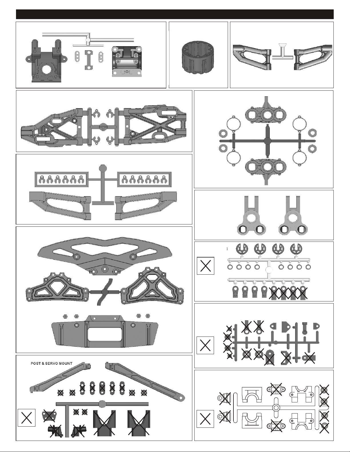
PLASTIC PARTS FOR USE
40533
FRONT AND REAR GEAR BOX
40717
FRONT AND REAR LOWER ARM
첿メ짾햡띠쉐
40716
FRONT UPPER ARM
40538
DIFF. CASE
40718
FRONT KNUCKLE ARM
쾧ガ쭌쪿츁 L.R띠쉐
40537
REAR UPPER ARM
40721
FRONT BUMPER
31304
REAR UPRIGHT
40643
SHOCK PLASTIC
Parts for
Not Use
30802
Throttle Linkage Plastic
40676
BODY POST & SERVO MOUNT
Parts for
Not Use
Parts for
Not Use
40040
CENTER DIFF. MOUNT PLASTIC PARTS
Parts for
Not Use
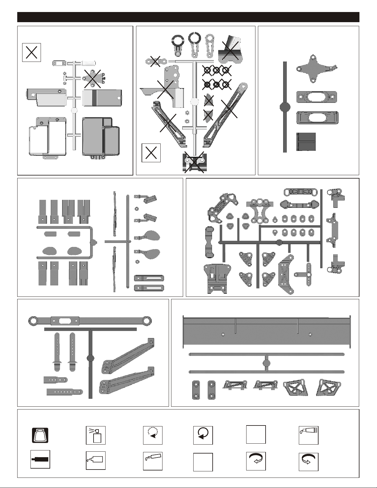
PLASTIC PARTS FOR USE
40541
RECEIVER BOX
Parts for
Not Use
40735
EXHAUST PIPE DETAIL PARTS
AND BACK MIRROR
40539
SERVO SAVER
Parts for
Not Use
40719
ARM HOLDER
40722
EXHAUST GAS DEFLECTOR
40720
SIDE IMPACT BUMPER AND BODY POST
SYMBOL USED THROUGHOUT THE INSTRUCTION MANUAL
Degrease With
Motor Spray
Apply OilApply Screw
BAG
Screw
Cem
nte
Parts Bag Used
Cement
Oil
Do Not
Over Tighten
Apply
Grease
40734
REAR WING AND WING MOUNT
Do Not
Over Tighten
Tighten
Apply Grease
1:1
Tighten
True-To-Scale
Ensure
Free
Movement
Rotate
Direction
Ensure Free
Movement
Clockwise
Rotation
Contact
Adhesive
Rotate
Direction
Contact Adhesive
Anti-clockwise
Rotation
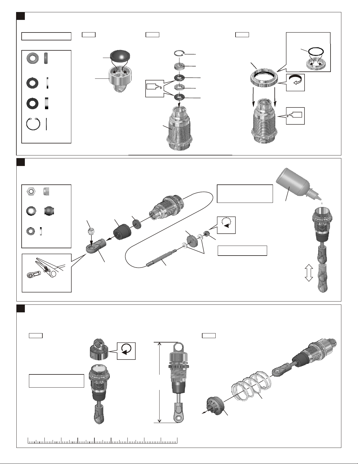
1
ASSEMBLY OF THE FRONT AND REAR SHOCKS
Make 4 shocks for Front and Rear.
40090
3.5mm O-Ring
40090 1mm Washer
40090
2mm Washer
40090
7mm R-Ring
2
ASSEMBLY OF THE SHOCK SHAFT
40060
2.5mmNylon Nut
30403
6mm Ball
2.6x5mm
Washer
*Be careful not to damage shock
shaft.
.....x8
.....x4
.....x4
.....x4
.....x4
.....x4
.....x8
Step 1
40640
Pressure Top
(Orange)
40633
Shock Cap
30403
6mm
Ball
40635
Shock Shaft
Dust Covers
40643
Shock Plastic
Ball End
(Short)
40637
Dust Felt
Step 2 Step 3
Oil
40737
Shock Body
40638
Shock Piston
40736
Shock Shaft
40090
7mm R-ring
40090
2mm Washer
40090
3.5mm O Ring
40090
1mm Washer
40090
3.5mm O Ring
2.6x5mm
Washer
40060
2.5mm
Nylon Nut
40634
Spring Adjuster
1. Pull down piston and pour oil
into shock cylinder to approx 90%.
2.To remove air bubbles by slowly
moving piston up and down.
Do Not
Over Thigten
Do not overtighten the 2.5 mm
nylon nut.
Fit the o-ringinto groove
before assembly.
40636
15x1mm
O-Ring
Rotate
Direction
Oil
Fill the shocks
with oil.
Move slowly.
UP
Down
3
ASSEMBLY OF THE SHOCK CAP AND SPRING
Step 1
1. Pull down piston, attach pressure
top and shock oil overflow with
tissue paper.
Tighten
* Makes total length for 84mm.
84mm
0 10 20 30 40 50 60 70 80 90
mm
1
Step 2
40643
Shock
Spring Holder
40738
Shock Spring(Red)
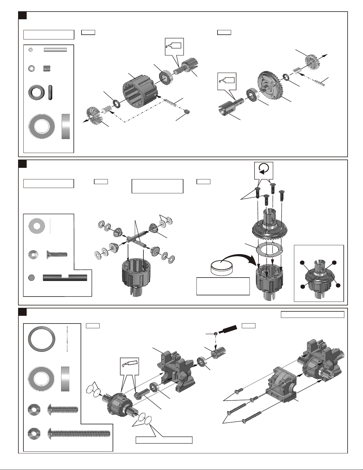
4
ASSEMBLY OF THE FRONT AND REAR DIFF.
Builds two differentials for front
and rear.
40010
2.5x13.8mm Pin
94034
4x4mm
Set Screw
40009
P6 O-Ring
36053
8x16mm Ball Bearing
5
ASSEMBLY OF THE FRONT AND REAR DIFF.
Builds two differentials for front
and rear.
.....x4
.....x2
.....x4
.....x4
Step 1 Step 2
40538
Diff. Case
40009
P6
O-Ring
40513
Diff. Gear
(Large)
Step 1 Step 2
NB. It is very important to remove
the 30776 washer if the gear
mesh is too tight.
30773
4mm
Cross Pin
36053
8X16mm
Ball Bearing
30776
4X10mm
Washer
Oil
4X4 mm
Set Screw
40514
Cap Joint
40010
2.5x13.8mm
Pin
Oil
3X12mm
Flat Head
Hex Screw
40514
Cap Joint
36053
8X16mm
Ball Bearing
Tighten
40513
Diff. Gear
40009
P6
O-Ring
40517
43T
Large
Bevel Gear
40010
2.5x13.8mm
Pin
30776
4x10mm
Washer
94020
3x12mm
Flat Head
Hex Screw
30773
4mm
Cross Pin
6
ASSEMBLY OF THE FRONT AND REAR GEAR CASE
.....x16
.....x8
.....x4
Step 1 Step 2
40533
Gear Case
40024
13x16x0.2mm
Shim
36053
8x16mm Ball Bearing
94011
4x16mm
Hex Screw
94015
4x35mm
Hex Screw
.....x8
.....x4
.....x4
.....x4
40024
13X16X0.2 mm
Shim
Apply
Grease
40024
13X16X0.2mm
Shim
’Adjust the backlash with the shims.
40513
Diff. Gear
(Small)
36053
8X16mm
Ball Bearing
40516
13T
Small Bevel Gear
Di
ff.
*Put the Diff. Oil #100000 for front
and the #50000 for Rear
*Fill the Diff. case to approx. 80%
with the Diff. Oil
5X4mm
Set Screw
40519
Cap Joint
36053
8X16mm
Ball Bearing
4X16mm
Hex Screw
4X35mm
Hex Screw
O
il
Sc
e
C
40011
Diff. Gasket
e
r w
ent
m
Tight the diff screws in this order.
1
4
Builds two gear case for front and rear.
40533
Gear Case
3
2
2

7
ASSEMBLY OF THE SERVO SAVER
Step 1 Step 2
40024
13x16x0.2mm
Shim
.....x2
40037
Steering Plate
40510
Servo Saver
Tube
40539
4x8mm
Plastic Flange
Bushing
Oil
40539
Servo Saver
Horn
40539
Servo Saver
Horn
Hex Screw
*Tighten the steering plate hex screw
all way down and then back it off 1/2
turn.
40746
Alum. Servo Saver
Connecting Plate
(Black)
Ensure
Free
Movement
40539
4x8mm
Plastic Flange
Bushing
40037
Steering Plat
Hex Screw
8
ASSEMBLY OF THE SERVO SAVER
.....x2
.....x2
40024
13X16X0.2mm
Shim
Step 1 Step 2
3mm
Nylon Nut
94003
3x10mm
Hex Screw
40531
Shock Ball
End Post
90018
3x25mm
Cap Screw
.....x5
.....x5
.....x2
.....x2
40719
Front Upper Arm
Holder (Plastic)
40719
Upper Arm
Adjuster
Rotate
Direction
40500
Servo Saver
Spring (Black)
40034
Servo Saver
Spring Tension
Adjuster
3x10mm
Hex Screw
40745
Front Plate
(Black)
3mm
Nylon Nut
Left
*Set the left and right hand side upper
arm adjuster in the same direction.
Right
40676
Center Brace
(Front)
* Notice the direction of the servo saver connecting plate.
40531
Shock Ball
End Post
40719
Front Shock
Mount
ew cr
S
n
Ceme t
3x25mm
Cap Screw
40539
Servo Saver
Horn
Screw
C nteme
9
ASSEMBLY OF THE SERVO SAVER
94026
4x12mm
Flat Head
Hex Screw
40539
6x10mm
Plastic Bushing
.....x2
.....x4
Screw
emeC nt
4x12mm
Flat Head
Hex Screw
Screw
ment
e
C
3
40511
Servo Saver
Post
40539
6x10x3mm
Plastic Bushing
40539
6x10x3mm
Plastic Bushing

10
ASSEMBLY OF THE STEERING TIE-ROD
Assembly for both left and right side.
Step 1 Step 2
40548
3mm
Nylon Nut(Thin Type)
40126
3X6mm
Flange Washer
40038
7mm Ball
36700
7mm Steering
Ball End
11
ASSEMBLY OF THE SERVO SAVER AND FRONT UPPER ARMS
.....x2
.....x2
.....x4
.....x4
40038
7mm Ball
36700
7mm Steering
Ball End
36790
4x46mm
Turnbuckle
36700
7mm Steering
Ball End
1:1
Approx. 29.30 mm
40038
7mm Ball
Step 1
4x10mm
Hex Screw
40548
3mm
Nylon Nut
(Thin Type)
Scr
ew
C
emen
40126
3X6mm
t
Flange Washer
3x15mm
Flat Head
Hex Screw
94020
3x12mm
Flat Head
Hex Screw
94026
4x12mm
Flat Head
Hex Screw
94009
4x10mm
Hex Screw
40525
3x48.1mm Arm Shaft
.....x2
.....x4
.....x2
.....X2
*Insert the upper arm adjust
into shock stay.
4x12mm
Flat Head
Hex Screw
40533
Front Plate Bad
Front
Step 2
40719
Upper Arm
Adjuster
40716
Caster Angle
Adjuster (2mm)
40716
Front Upper
Arm
40716
Caster Angle
Adjuster
(1mm and 3mm)
40525
3x48.1mm
Arm Shaft
40525
3x48.1mm
Arm Shaft
3x12mm
Flat Head
Hex Screw
40719
Shock Stay
Left
*Set the left and right hand side upper
arm adjuster in the same direction.
Right
4
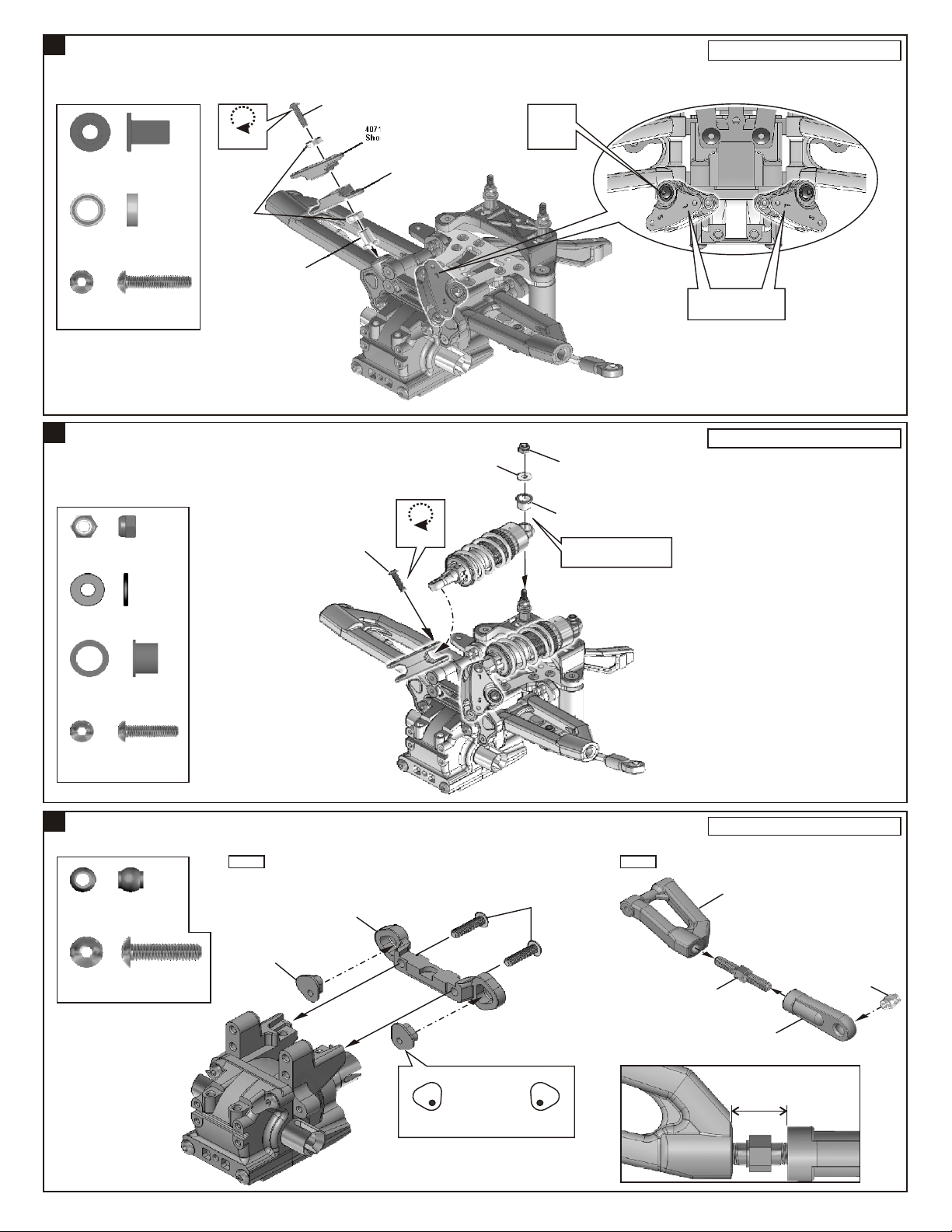
12
ASSEMBLY OF THE FRONT SHOCK STAY
3x15mm
Hex Screw
40719
Do Not
36742
Shock Cap
Bushing
39242
5x8x2.5mm
Ball Bearing
94005
3x16mm
Hex Screw
13
ASSEMBLY OF THE FRONT SHOCKS ONTO SHOCK STAY
.....X2
.....X4
.....x2
Over Tighten
39242
5x8x2.5mm
Ball Bearing
36742
Bushing
Shock Mount(A)
40719
Shock Mount(B)
3x8mm
Washer
Ensure
Free
Movement
3mm
Nylon Nut
Assembly for both left and right side.
*Notice"L"make are for
inside.
Assembly for both left and right side.
94041
3mm
Nylon Nut
94040
3x8mm
Washer
40643
Shock Cap
Washer
94004
3x12mm
Hex Screw
14
ASSEMBLY OF THE REAR UPPER ARMS
.....x2
.....x2
.....x2
.....x2
Step 1 Step 2
36850
7mm
Ball
94011
4x16mm
Hex Screw
.....x2
.....x2
40719
Upper Arm
Adjuster
3x12mm
Hex Screw
40719
Rear Upper Arm
Holder (Plastic)
Do Not
Over Tighten
4x16mm
Hex Screw
40643
Shock Cap
Washer
*Take the shock cap washer
from the shock plastic tree.
Assembly for both left and right side.
40537
Rear Upper Arm
36861
5x35mm
Turnbuckle
36850
7mm
Ball
Left
*Set the left and right hand side upper
arm adjuster in the same direction.
Right
5
40065
Upper Arm
Plastic Rod End
11¡G
Approx. 12.5 mm
 Loading...