

Page 1
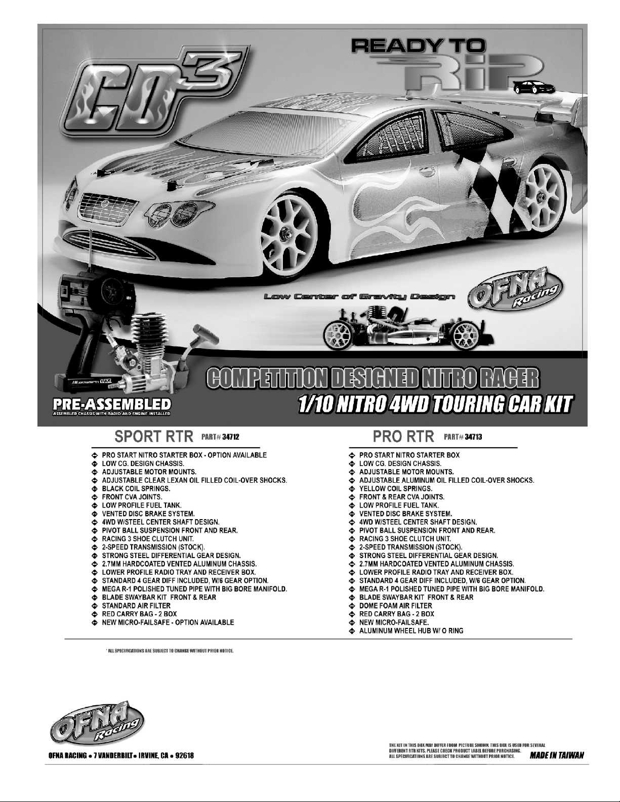
CD-3 SPORT RTR and PRO RTR
ASSEMBLY INSTRUCTIONS
Page 2
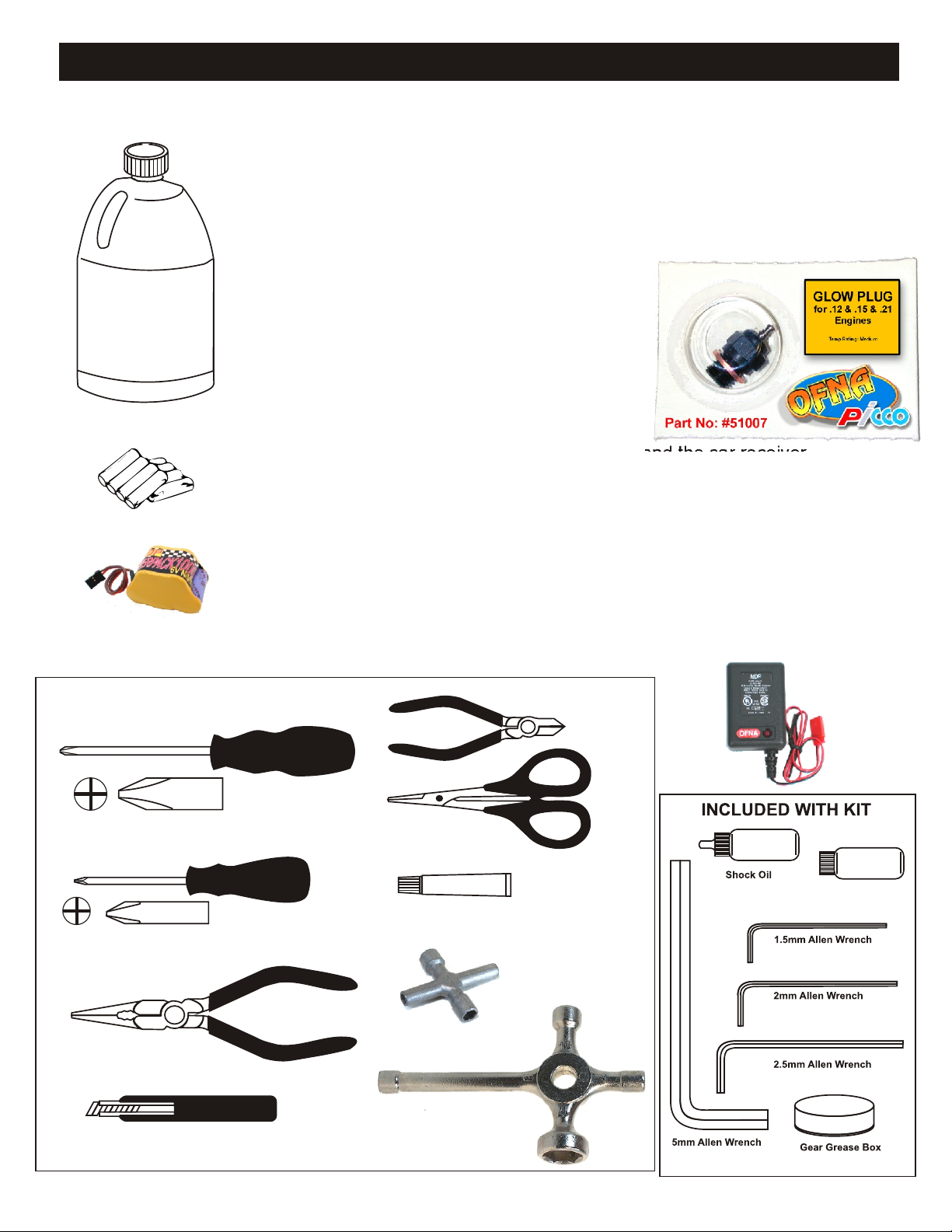
REQUIRED FOR OPERATION
THINGS NEEDED
Glow Fuel
20%
AA Batteries ( 12 pcs )
You will need to buy a few items to start the engine and run the car.
• Use 20% nitro CAR fuel. Do not use airplane or helli fuels, they will
over heat engine.
• Buy SHORT glow plugs, OFNA/PICCO Plu (#51007 or 51008) are
long therefore use two copper washers. Use plugs without idle bar.
Always use two copper washers with Picco glow plugs.
In your box you will find..
• #10163 - 250cc Fuel Bottle
• #10219 - Red “D” size glow heater
These parts change depending on stock!
You need to get batteries for the radio transmitter and the car receiver
packs.
• Radio TX needs (8) eight AA batteries.
• Car needs (4) four AA Ni-cad batteries, Alkaline type batteries will
work, but braking will be reduced. The best is to use a 5 cell hump
pack for increased voltage..
Recommended Option:
#10212 NiHm Hump Pack,
see charger 10214.
TOOLS NOT INCLUDED IN KIT,
BUT NEEDED TO MAINTAIN YOUR CAR.
Phillips Type Screw Drivers ( L )
Phillips Type Screw Drivers ( S )
Needle Nose Pliers
You may want to upgrade the car battery pack to a Ni-Cad or NiHm 5
cell type(600AE). This will give more run time. OFNA #10212
Cutter
Curved Scissors
Instant Cement
Cross Wrench
#17109 $3.95
10214
Over-nite
Charger
Diff Oil Silicone
Knife
Glow Plug & 17MM Cross Wrench
#10801 $6.95
Page 3

MUST READ THIS BEFORE RUNNING
Running a nitro kit is fun and easy, but to make this a safe rusting.
and good experience you must observe a few rules. This
kit is extremely fast, easily over 40MPH, and can seriously
injure someone if you are not careful.
Where to run car?
• Any running area you choose must be dry. Do not run
car near any water or wet dirt.
• Do not run on public streets. It is very easy to have the
car run over or damaged by hitting the curb.
• Do not operate car in tight confined places. The car is
very fast and will easily hit something.
• Do not run near people or animals.
and will too easily hit someone.
• Due noise, you will want to consider the surrounding
area when operating the car.
• Do not operate the car at night. You will not be able to
drive it without hitting something.
• Do not operate the car indoors. Engine exhaust is not
healthy.
Glow Fuel
• Glow fuel is poisonous!
• Glow fuel is flammable!
• Do not leave in fuel bottle with lid off at any time. label for additional precautions.
• Do not use any fuel other than glow fuel in this engine.
First Time Starting the Engine
Caution! When starting engine make sure the following is
observed. • Always turn off the car BEFORE turning off radio.
• Set engine Master needle to 3 turns (rich setting)
• Do not do this alone, get an experienced friend to help at • DAMAGE DUE CAR RUN AWAY IS NOT A WARRANTY
first. ISSUE.
• Fill fuel tank, try not to spill fuel. Do not spill fuel on
receiver
• Hold car off the ground, so it will not runaway when first
starts
• Turn on Radio and check the linkage before starting
engine.
• Turn on car receiver battery switch.
• Always have an air filter on the carburetor to keep dirt
out.
Engine Break-in
• See Engine Page.
The car is very fast
• Clean oil and dirt from chassis with a degreaser.
Precautions
• This kit is not a toy. Always run car with a second
person as a spotter and pitman.
• Hot Parts - The pipe, manifold, engine and head are very
hot and will cause burns.
• Rotating Parts - Keep hands away from the drive train,
wheels, and engine when engine is running.
• Radio - Check batteries life before running the car. If
radio does not have full control of the car with steering
and/or throttle/brake do not run until corrected. Failure to
correct this will result in possible injury and damage to the
car or property.
• Glow fuel - Do leave the glow fuel unattended with the lid
off. Fuel contains Methanol and Nitro Methane and is
flammable and poisonous.
Store fuel in cool ventilated location. Refer the glow fuel
• Car Fuel tank - Never store fuel in car tank, it will ruin the
engine if left in tank.
IF YOU DO NOT BREAK-IN ENGINE
CORRECTLY, MAINLY AT LOW RPM,
YOU WILL BREAK THE CONNECTING
ROD!
FAILURE TO NOT READ AND
FOLLOW BREAK-IN ENGINE
Emergency Stopping Engine When Running
• Remove air filter and cover carb. intake.
• Squeeze fuel line and hold until engine stops.
• With a rag, cover exhaust outlet.
Storing Car After Running
• Remove fuel from tank and fuel lines
• Turn off radio in car
• Put a few drops of after run in engine to keep it from
INSTRUCTIONS WILL VOID
WARRANTY!
CHECK RADIO SETTING AND
LINKAGE BEFORE STARTING
Page 4
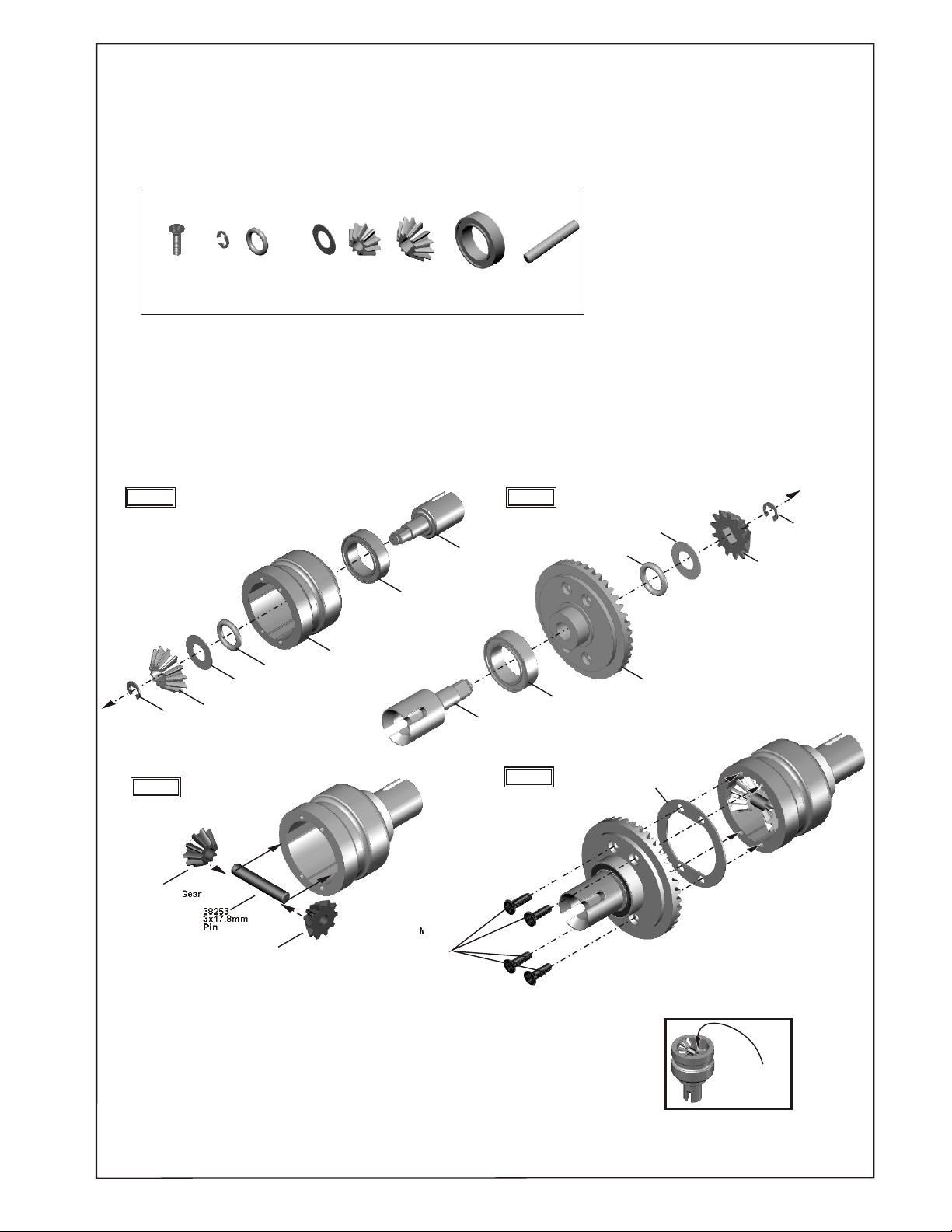
ASSEMBLY OF THE DIFFERENTIAL
(Build two differentials for front and rear.)
90020
94052
M2x7mm
Flat Head
Screw
2.5mm
E-Ring
38278
5x8x1.5mm
O-Ring
38632
5x10mm
Washer
38256
Diff.Gear
(small)
Diff.Gear
(Large))
37771
37450
10x15x4mm
Bearing
38253
3x17.8mm
Pin
Step 1
90020
E-Ring
2.5mm
Step 3
38256
10T Diff.Gear
(small)
37771
13T
Diff.Gear
38253
3x17.8mm
Pin
38632
Washer
5x10mm
38256
38278
5x8x1.5mm
O-Ring
10T Diff.Gear
(small)
38252
Diff.Case
37450
10x15x4mm
Ball Bearing
94052
M2x7mm
Flat Head
Screw
38255
Cap Joint
38255
Cap Joint
Step 2
Step 4
37450
10x15x4mm
Ball Bearing
38278
5x8x1.5mm
O-Ring
38287
Diff.Gasket
38632
5x10mm
Washer
38257
Large
Bevel Gear
90020
2.5mm
E-Ring
37771
13T
Diff.Gear(Large)
Put the grease
into the diff.
case before
assembly.
Page 5
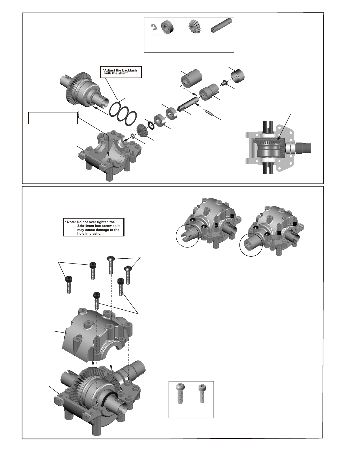
ASSEMBLY OF THE GEAR BOX
(Build two gear box for front and rear.)
*Adjust the backlash
with the shim*
38254
12x15x0.25mm
Shim
Note: Follow the instruction
to put the correct shim
in the right place.
38251
Gear case
90020
2.5mm
E-Ring
38633
5x8x0.8mm
Washer
2.5mm
E-Ring
90020
37430
5x11x4mm
Ball Bearing
38519
Bevel Gear
Cap Joint (R)
37430
5x11x4mm
Ball Bearing
37340
5x11x4mm
38258
16T Bevel Gear
(small)
Ball Bearing
38258
16T Bevel Gear
(small)
38526
Bevel Gear
Shaft (small)
* For the good gear mesh,
put the 5x8x0.8 washer
between L-06 and E-43.
Bevel Gear
Shaft (small)
38530
Steel Ring
(For Front Plastic
Cap Joint)
38526
38519
Bevel Gear
Cap Joint (F)
37400
2x8.8mm
Pin
To test the effectiveness of the gear
differential, hold the gear tightly with one
hand and turn one cap joint.
Does the other cap joint move in the
opposite direction and smoothly?
¡¯CHECKI NG YOUR DI FFE RENT I AL
ASSEMBLY
If gear differential does not move smoothly,
assemble the gear diff. once again.
94001
M3x4mm
Screw
* Put the gear in the
right position.
ASSEMBLY OF THE FRONT GEAR BOX
(Builds a gear box for the front.)
* Note: Do not over tighten the
2.6x10mm hex screw as it
may cause damage to the
hole in plastic.
94050
2.6x10mm
Hex Screw
38251
Gear Case
94004
M3X12mm
Screw
2.6x10mm
Hex Screw
For Front
For Rear
38251
Gear Case
94004
M3X12mm
Screw
94050
2.6x10mm
Hex Screw
* The picture shown is the gear box after
assembly.
* It is normal for the gears to make a noise.
After brake-in, the noise will be reduced.
Page 6
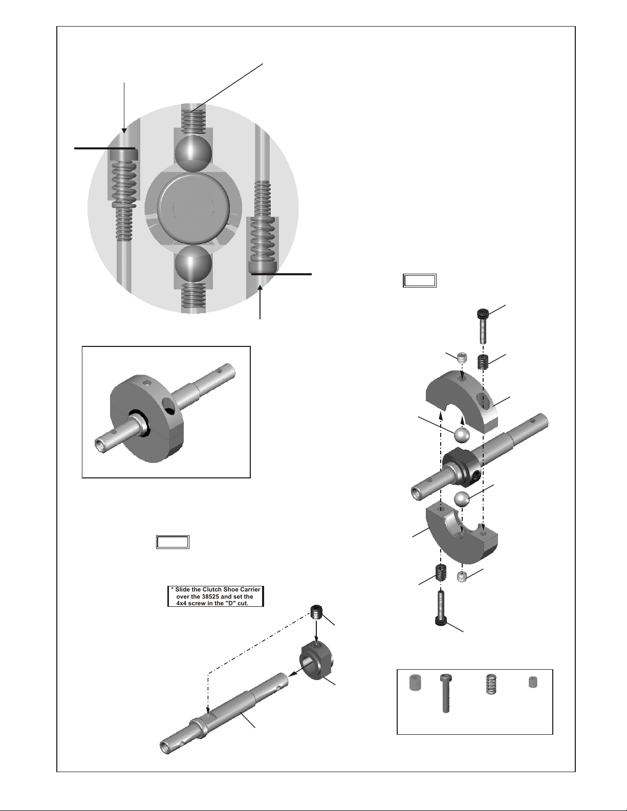
ASSEMBLY OF 2-SPEED CLUTCH TRIGGER DISC
SET BALL TO REST ON CAM, NOT PUSHING. IF
SCREW AS SHOWN,
LEVEL WITH HOLE EDGE
TOO TIGHT, THE BALL WILL PUSH ON CAM
SPREADING SHOE DISC AND WILL NOT FIT
INTO ALUM. CLUTCH BELL #38296
CARE MUST BE TAKEN TO BUILD
THIS ASSEMBLY CORRECTLY,
OTHERWISE 2-SPEED WILL NOT
ADJUST AND MAY NOT WORK AT ALL.
IN FACT, IF 2-SPEED DOES NOT
SHIFT, CHECK OUT THIS ASSEMBLY!.
Step 2
35325
M2x10mm
Hex Screw
SCREW AS SHOWN,
LEVEL WITH HOLE EDGE
ASSEMBLY OF THE TWO SPEED CLUTCH SHOES
Step 1
* Slide the Clutch Shoe Carrier
over the 38525 and set the
4x4 screw in the "D" cut.
94034
4x4mm
Set Screw
38315
Steel Ball
38312
2 Speed
Clutch Shoe
38313
Spring
94033
3x3mm
Set Screw
35325
M2x10mm
Hex Screw
38315
Steell Ball
94033
3x3mm
Set Screw
38313
Spring
38312
2 Speed
Clutch Shoe
38525
2 Speed Main Shaft
(Cd3 only)
38316
Clutch Shoe
Carrier
94034
Set Screw
4x4mm
M2x10mm
Hex Screw
38313
Spring
94033
3x3mm
Set Screw
Page 7
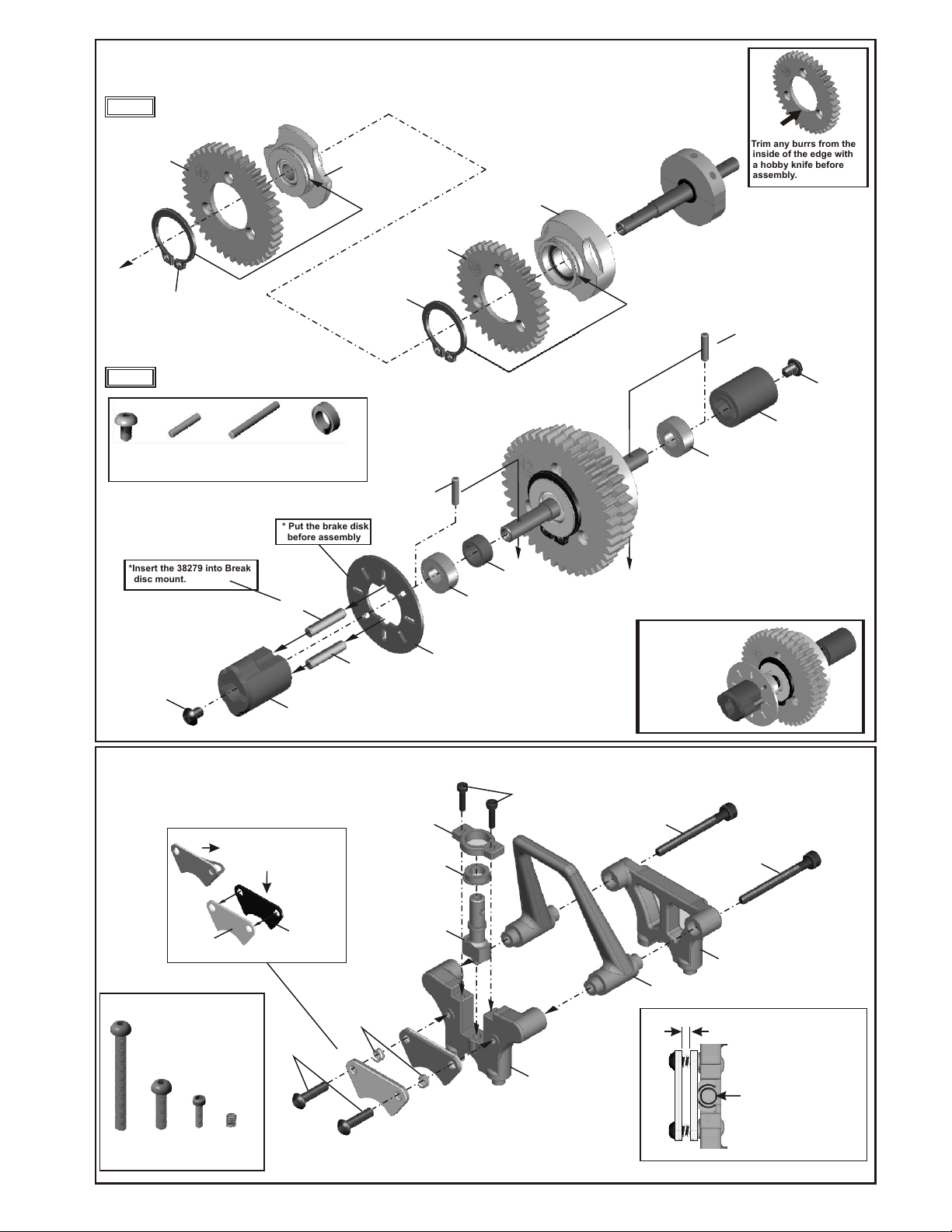
ASSEMBLY OF THE TWO SPEED GEAR
Step 1
38301
Spur Gear
38297
Retaining Ring
Step 2
94001
M3x4mm
screw
37400
2x8.8mm
Pin
*Insert the 38279 into Break
disc mount.
38279
3x13.8mm
Pin
38295
1 st Gear Carrier
(One-Way)
37430
5x11x4mm
Ball Bearing
* Put the brake disk
before assembly
38279
3x13.8mm
Pin
38300
38T
Spur Gear
38297
Retaining Ring
37400
2x8.8mm
Pin
38296
2nd Gear
Clutch Bell
(Ball Bearing)
38519
6x18.5x4mm
Plastic Washer
37430
5x11x4mm
Ball Bearing
* Trim any burrs from the
inside of the edge with
a hobby knife before
assembly.
37400
2x8.8mm
Pin
37430
5x11x4mm
Ball Bearing
38519
Bevel Gear
Cap Joint(R)
94001
M3x4mm
screw
40042
94001
M3x4mm
Screw
38519
Brake Disc
Mount
38279
3x13.8mm
Pin
ASSEMBLY OF THE BRAKE AND DIFF. MOUNT
38519
Bushing Support
M3x30mm
Screw
94000
M3x12mm
Screw
94004
Remove the double-side
tape before assembly.
38271
Brake Pad
Brake
Spring
40040
M2x8mm
Hex Screw
94047
38272
Brake Pad
Linings
94004
M3x12mm
Screw
40040
Blake Pad
Spring
38519
Plastic Bushing
38273
Brake Cam
Brake Disk
94047
M2x8mm
Hex Screw
38520
Brake Mount
(Upper)(Front)
94000
M3x30mm
Screw
38520
Roll Bar
94000
M3x30mm
Screw
38520
Brake Mount
(Upper)(Rear)
1.5mm
* Leave the 1.5mm space
between brake pads.
Please notice!
* Position the brake cam
in the direction as shown.
Page 8
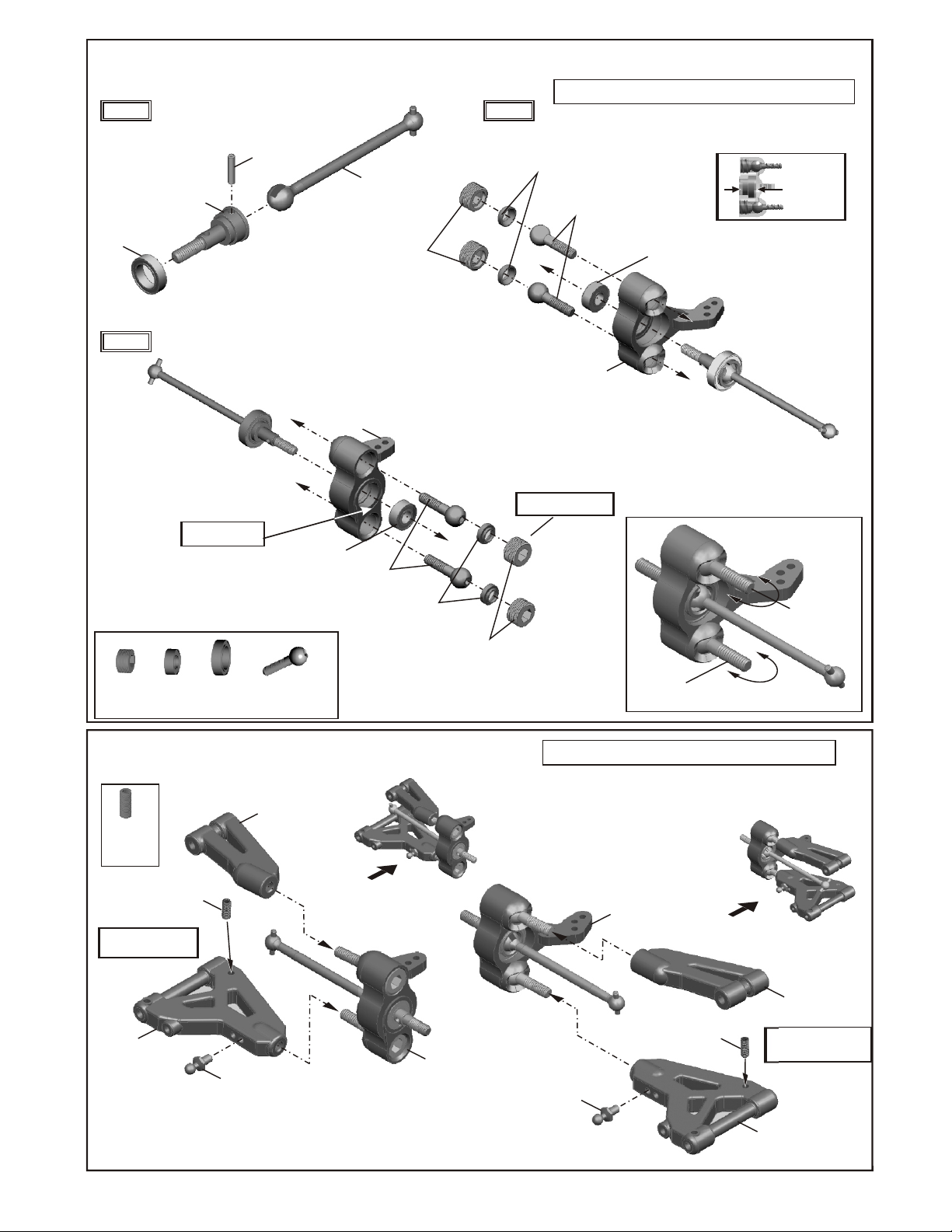
ASSEMBLY OF THE FRONT KNUCKLE ARMS AND CVD SHAFT
Step 1
37450
10x15x4mm
Ball Bearing
Step 3
39150
10mm Alum.
Set Screw
38406
CVD Shaft
*"L" make are for
left-side.
37430
5x11x4mm
Ball Bearing
37450
10x15x4mm
Ball Bearing
38524
2x9.8mm
Pin
39140
8mm
Steering Ball
38265
Front Knuckle
Arm (Left)
37430
5x11x4mm
Ball Bearing
38523
CVA Dog Bone
39150
10mm Alum.
Set Screw
39140
8mm
Steering Ball
39141
8mm
Steering Ball
Washer
Step 2
39150
10mm Alum.
Set Screw
39141
8mm
Steering Ball
Washer
*Notice the direction
of the hex screw.
Assembly of the right and left-side are the same.
Push 2 ball
bearings into
knuckle arm
39140
8mm
Steering Ball
38265
Front Knuckle
Arm (Right)
37430
5x11x4mm
Ball Bearing
Make steering
ball move
smooth.
as shown.
Make steering
ball move
smooth.
ASSEMBLY OF THE FRONT SUSPENSION ARMS
38399
Front Upper
94035
3x8 mm
Set Screw
3 x 8mm set screw is
used to adjust the
ride height.
38399
Front Lower
Arm
94035
3x8 mm
Set Screw
Arm
37360
4mm
Ball&Socket
FRONT KNUCKLE
ARM ASSEMBLY.
LEFT SIDE
Assembly of the right and left-side are the same.
RIGHT SIDE
FRONT KNUCKLE
ARM ASSEMBLY.
38399
Front Upper Arm
37360
4mm
Ball&Socket
94035
3x8 mm
Set Screw
A 3 x 8mm set screw
is used to adjust the
ride height.
38399
Front Lower Arm
Page 9
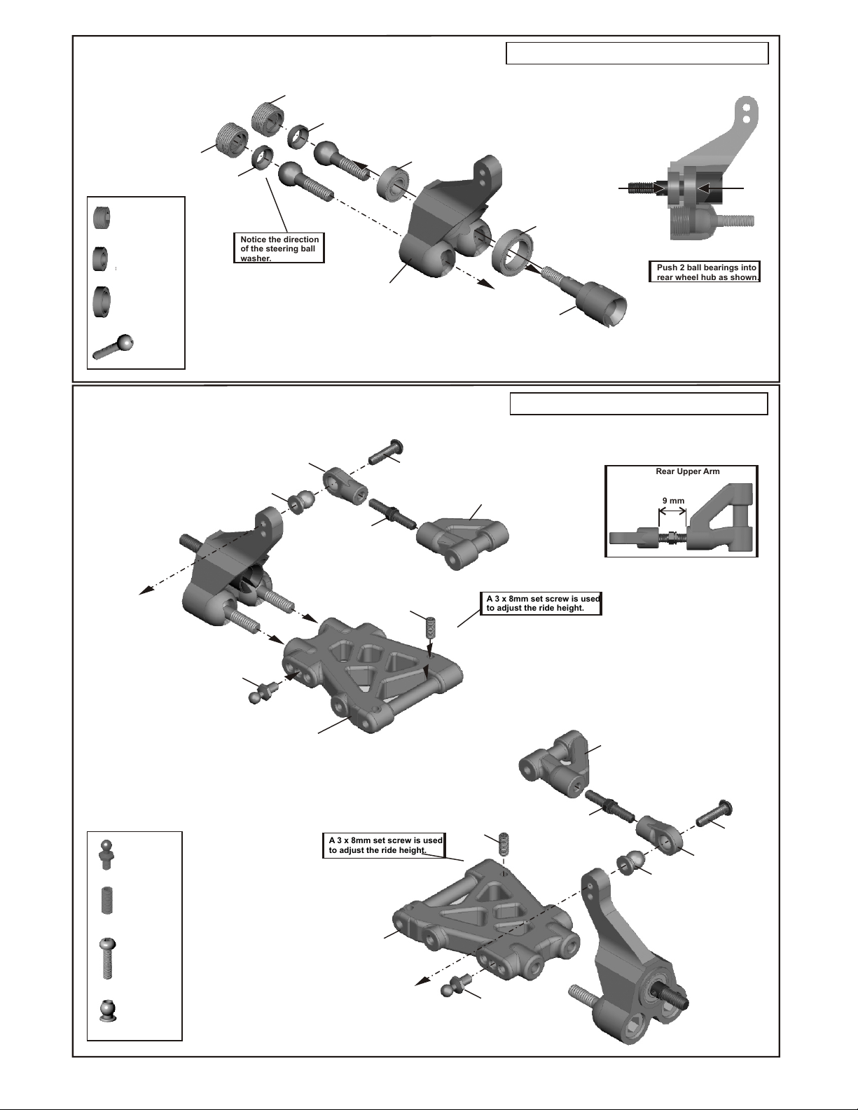
ASSEMBLY OF THE REAR WHEEL HUB
39150
10mm Alum.
Set Screw
39141
8mm
Steering Ball
Washer
39150
39150
10mm Alum.
Set Screw
37430
5x11x4mm
Ball Bearing
37450
10x15x4mm
Ball Bearing
39140
8mm
Steering Ball
10mm Alum.
Set Screw
39141
8mm
Steering Ball
Washer
Notice the direction
of the steering ball
washer.
37430
5x11x4mm
Ball Bearing
38266
Rear Wheel
Hub
Assembly of the right and left-side are the same.
37450
10x15x4mm
Ball Bearing
38267
Rear Wheel
Axle Shaft
Push
Push 2 ball bearings into
rear wheel hub as shown.
Push
ASSEMBLY OF THE REAR SUSPENSION ARMS
38399
Upper Arm
Plastic Rod End
(Left- Hand Side)
37360
Ball & Socket
94035
3x8 mm
Set Screw
94005
M3x16 mm
Screw
37370
6 mm
Ball & Socket
37370
6 mm
Ball & Socket
37360
Ball & Socket
38399
3x20mm
Turnbuckle
38399
Rear Lower Arm
A 3 x 8mm set screw is used
to adjust the ride height.
38399
Rear Lower Arm
3x8 mm
Set Screw
94005
M3x16 mm
Screw
94035
(Right- Hand Side)
Assembly of the right and left-side are the same.
38399
Rear Upper Arm
A 3 x 8mm set screw is used
to adjust the ride height.
94035
3x8 mm
Set Screw
37360
Ball & Socket
38398
3x20mm
Turnbuckle
Rear Upper Arm
38399
Rear Upper Arm
37370
6 mm
Ball & Socket
9 mm
94005
M3x16 mm
Screw
38399
Upper Arm
Plastic Rod End
Page 10
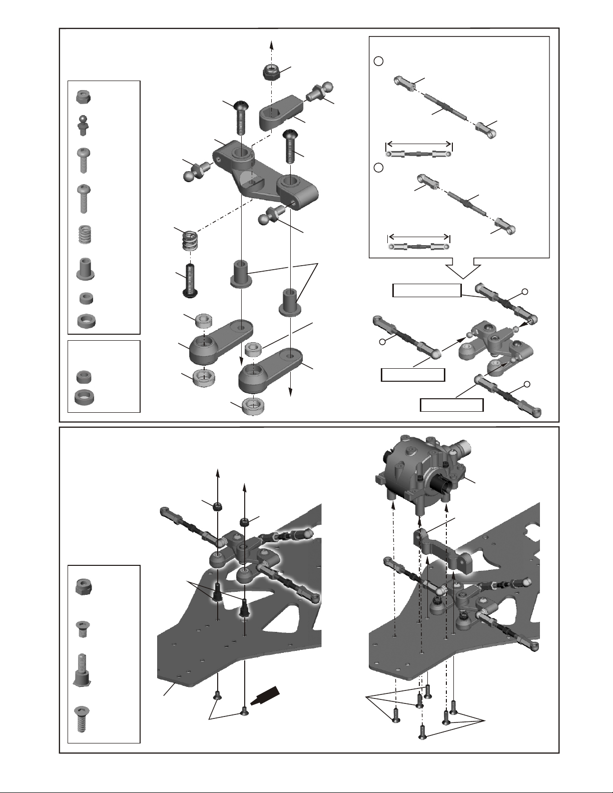
ASSEMBLY OF THE SEVRO SAVER
94041
M3
Nylon Nut
37360
4mm
Ball & Socket
94003
M3x10mm
Screw
94004
M3x12mm
Screw
38288
Servo Saver
Spring
36742
Servo Saver
Bushing
38276
3x6 mm
Brass Bushing
38277
5x8 mm
Brass Bushing
Option:
38644 Ballbearing Set
(For servo Saver )
3x6x2.5m
Ballbearing x2
35958
5x8x2.5mm
Ballbearing x2
37360
4mm
Ball & Socket
38288
Servo Saver
Spring
94004
M3x12mm
Screw
38644
3x6x2.5mm
Brass Bushing
38289
Servo Saver
35958
5x8x2.5 mm
Brass Bushing
94004
M3x12mm
Screw
38289
Servo Saver
35958
5x8x2.5 mm
Brass
Bushing
94041
M3
Nylon Nut
38289
Servo Saver
94004
M3x12mm
Screw
37360
4mm
Ball & Socket
37360
4mm
Ball & Socket
36742
Servo Saver
Bushing
38644
3x6x2.5mm
Brass Bushing
38289
Servo Saver
*Use the long ball end for both steering rod and steering servo rod.
Steering Rod
A
Steering Servo Rod
B
A
Put steering rod into
4mm ball & socket.
37650
4mm
Ball End (Long)
38281
3x40mm
Turnbuckle
Approx 57 mm
37650
4mm
Ball End (Long)
Approx 54 mm
Snap steering rod into
4mm ball & socket.
Put steering rod into
4mm ball & socket.
37650
4mm
Ball End (Long)
Made two steering rod for left and
right hand side.
38281
3x36mm
Turnbuckle
37650
4mm
Ball End
(Long)
B
A
ASSEMBLY OF THE SEVRO SAVER
AND STEERING RODS
94041
M3
Nylon Nut
94041
M3
Nylon Nut
94018
M3x5mm
Flat Head
Hex Screw
38275
Servo saver
Screw
94019
M3x10mm
Flat Head
HexScrew
38275
Servo saver
Screw
38528
Cd3 Stock
Chassis
94018
M3x5mm
Flat Head
Hex Screw
94041
M3
Nylon Nut
t
c
S rew
emen
C
94019
M3x10mm
Flat Head
HexScrew
Front Gear
Box Assembly.
38263
Arm Holder for 0
(Lower/Rear)
94019
M3x10mm
Flat Head
HexScrew
Page 11
ASSEMBLY OF THE FRONT ARM HOLDER
ONTO CHASSIS
38263
Lower Arm Holder for 0 and 1.5 and
2.5 degree.
Assembly of the right and left-side are the same.
Use the 0 degree for
front arm holder.
For assembly stabilizer:
* Use a 3mm drill to
hone out the front
lower arm holder.
M3x3mm
M3x10mm
Flat Head
Hex Screw
4mm
Ball & Socket
3x55mm
Lower Arm Shaft
94033
94019
37360
38419
38263
Arm Holder
(Front/Lower)
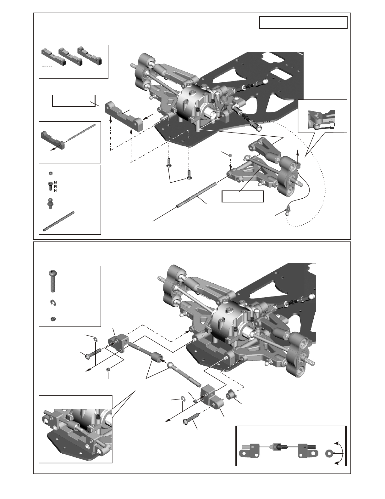
ASSEMBLY OF THE FRONT STABILIZER
94019
M3x10mm
Flat Head
HexScrew
M3x3mm
Insert the drive shaft
before assembly.
38419
3X55mm
Lower Arm Shaft
37360
4mm
Ball & Socket
*Put steering rod into
..
4mm ball & socket
M3x16mm
Screw
2.5mm
E-Ring
M3x3mm
Set Screw
94005
Assembly of front stabilizer
94005
90020
94033
2.5mm
E-Ring
M3x16mm
Screw
90020
38418
Stabilizer
Mount
M3x3mm
Set Screw
94033
38420
Stabilizer
2.5mm
E-Ring
90020
94033
M3x3mm
Set Screw
M3x16mm
Screw
94005
Stabilizer
Mount
38418
Stabilizer
Balance
Adjuster
*Keep stabilizer ball in the center.
*Turn stabilizer balance adjuster to
adjust the stabilizer to the same angle.
Center
Page 12
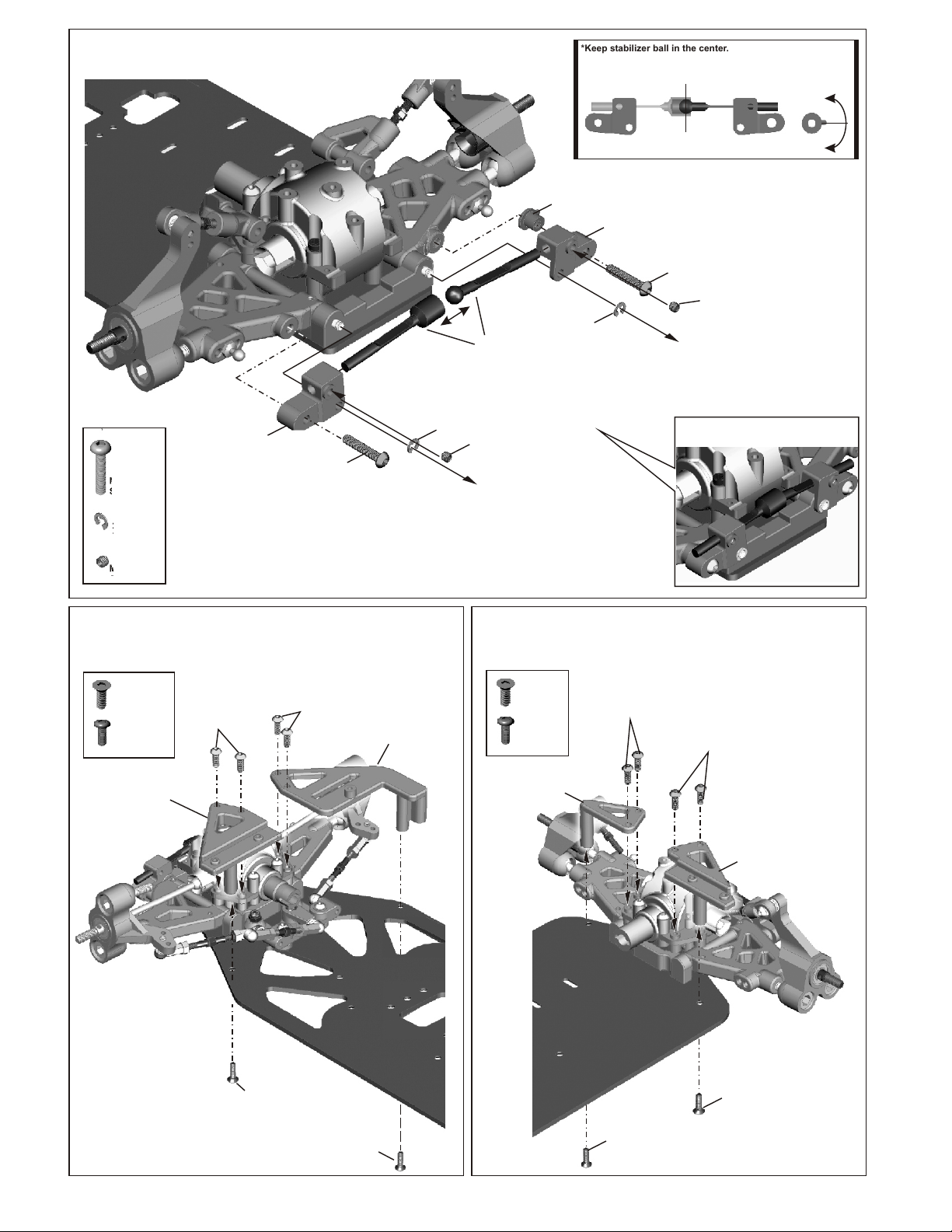
ASSEMBLY OF THE REAR STABILZER
38418
94005
M3X16mm
Screw
Stabilizer
Mount
94005
M3x16mm
Screw
90020
2.5mm
E-Ring
38420
stabilizer
94033
M3x3mm
Set screw
*Keep stabilizer ball in the center.
*Turn stabilizer balance adjuster to
adjust the stabilizer to the same angle.
38418
Stabilizer
Balance
Adjuster
90020
2.5mm
E-Ring
38418
Stabilizer
Mount
Center
94005
M3x16mm
Screw
94033
M3x3mm
Set screw
Assembly of rear stabilizer
2.5mm
E-Ring
94003
M3X3mm
Set Screw
ASSEMBLY OF THE FRONT STIFFENER
ONTO CHASSIS
94019
M3x10mm
Flat Head
Hex Screw
94032
M3x8mm
Screw
38518
Front Stiffener (Left)
94032
M3x8mm
Screw
94032
M3x8mm
Screw
38518
Front Stiffener (Right)
ASSEMBLY OF THE REAR STIFFENER
ONTO CHASSIS
94019
M3x10mm
Flat Head
Hex Screw
94002
M3x8mm
Screw
38518
Rear Stiffener (Right)
94002
M3x8mm
Screw
94002
M3x8mm
Screw
38518
Rear Stiffener (Left)
94019
M3x10mm
Flat Head
HexScrew
94019
M3x10mm
Flat Head
HexScrew
94019
M3x10mm
Flat Head
HexScrew
94019
M3x10mm
Flat Head
HexScrew
Page 13

ASSEMBLY OF THE REAR GEAR BOX
AND ARM HOLDER ONTO CHASSIS
38263
Arm holder
M3x10mm
Flat Head
HexScrew
(Rear/Front)
Use the 0 degree for
rear arm holder.
94019
M3x10mm
Flat Head
HexScrew
94019
M3x10mm
Flat Head
HexScrew
Rear Gear Box
Assembly
94019
M3x10mm
Flat Head
HexScrew
ASSEMBLY OF THE REAR BLOCK ONTO CHASSIS
94033
M3x3mm
Set Screw
M3x10mm
Flat Head
HexScrew
38419
3x55mm
Lower Arm Shaft
94019
38263
Lower Arm Holder for 0 and 1.5 and
2.5 degree.
Use the 0 degree for
rear arm holder.
38263
Arm Holder
(Rear / Rear)
Assembly of the right and left-side are the same.
94033
M3x3mm
Set Screw
94019
M3x10mm
Flat Head
Hex Screw
38419
3x55mm
Lower Arm Shaft
Page 14

ASSEMBLY OF THE TWO SPEED ONTO CHASSIS
The mark on the center
drive shaft is used for the front.
M3x30mm
Flat Head
Hex Screw
M3x25mm
Flat Head
Hex Screw
38527
Center Drive Shaft
(Long/Front)
M3x25mm
Flat Head
Hex Screw
Brake Mount
Assembly (Upper)
2-Speed Assembly
38520
Brake Mount
(Lower)
*Insert the center drive shaft
before assembly the two speed
onto chassis.
38527
Center Drive Shaft
(Short/Rear)
M3x10mm
Flat Head
Hex Screw
ASSEMBLY OF THE STEERING SERVO
94002
M3X8mm
Screw
94003
M3X10mm
Screw
M3X8mm
Washer
M3X10mm
Screw
Align the servo horn in 90 degree.
Degree
90
M3X8mm
Washer
Screw
37360
4mm
Ball & Socket
38520
Servo Post Washer
10768
Steering
Servo Horn
M3x10mm
Flat Head
Hex Screw
38520
Servo Post
M3X8mm
Screw
Steering Servo
M3X8mm
Washer
M3x25mm
Flat Head
Hex Screw
M3X8mm
Screw
38520
Servo Post
38520
Servo Post Washer
M3x30mm
Flat Head
Hex Screw
Steering Servo After Assembly.
Note:
Use M3x30mm flat head screw
only in this position.
38517
Radio Tray
Use the screw
from your servo.
M3X10mm
Screw
Page 15

ASSEMBLY OF THE FRONT SHOCK STAY ONTO FRONT
GEAR BOX
90020
94004
M3x12mm
Screw
94002
M3x8mm
Screw
90020
2.5mm
E-Ring
2.5mm
E-Ring
38261
Front Upper
Arm Shaft
94004
M3x12mm
Screw
Assembly of the right and left-side are the same.
94002
M3x8mm
Screw
39141
Insert the front caster angle adjuster into front upper arm.
39141
Caster Angle
Adjuster(1.5mm)
1.5mm
1mm
Caster Angle
Adjuster
(1.0mm)
ASSEMBLY OF THE REAR SHOCK STAY ONTO REAR
GEAR BOX
38268
Rear Drive
Shaft
94002 94004
M3x8mm
Screw
M3x12mm
Screw
90020
2.5mm
E-Ring
Assembly of the right and left-side are the same.
90020
2.5mm
E-Ring
38261
Front Upper
Arm Shaft
90020
2.5mm
E-Ring
94004
M3x12mm
Screw
94002
M3x8mm
Screw
38268
Rear Drive
Shaft
* Insert the rear driver shaft
before assembly the upper arm.
90020
2.5mm
E-Ring
90020
2.5mm
E-Ring
Page 16

ASSEMBLY OF THE LEXAN SHOCK ABSORBERS
(USED ON SPORT RTR MODELS)
37070
37650
4mm
Ball End
3mm O-Ring
2mm E-Ring
37070
3mm O-Ring
2mm E-Ring
38325
Shock Shaft
37070
3mm O-Ring
37100
Front Cap
2mm E-Ring
37100
Piston
39030
Clear Lexan
Shock Body
FILLING THE SHOCKS WITH OIL
OilOil
Shock Oil
Use the No.2 for two
hole piston from
shock plastic tree.
ASSEMBLY THE SHOCK SPRING
38330
Shock Cap
(Gray)
37100
Ball end
37080
Pressure Top
Spring collar
38326
Shock Spring
37100
Spring
tension adjust
Pull down piston
37967
P3
O-Ring
(2 pcs)
and pour oil into
shock cylinder.
Remove air bubbles
by slowly moving
piston up and down
several times.
2mm
E-Ring
38325
Shock Shaft
*Insert the o-ring
into the groove
of the adjust nut.
37100
Piston
Use the No.2 for two hole
piston from shock plastic
tree.
37966
P12 O-Ring
Use the short ball end .
ASSEMBLY OF THE ALUMINUM CNC SHOCK ABSORBERS
(USED ON PRO RTR MODELS)
37967
Washer
(Block)
37965
Alum Shock Body
Step 1
The C-Ring must fit
into the groove.
37967
C-Ring
Step 2
Use a little shock oil to
lubricate o-rings before
screwing on adjusting nut.
37100
Spring Holder
ASSEMBLY THE SHOCK SPRING
Use the short shock
ball end.
38330 GRAY
Shock Cap
(Gray)
37100
Ball End
( Short)
37080
Pressure Top
37650
4mm
Ball End
* Use the short ball end .
38331-GRAY
Adjust Nut(Gray)
FILLING THE SHOCKS WITH OIL
OilOil
Pull down piston
and pour oil into
shock cylinder.
Shock Oil
Remove air bubbles
by slowly moving
piston up and down
several times.
38326
Shock Spring
37100
Spring Holder
Page 17

ASSEMBLY OF THE FUEL TANK ONTO CHASSIS
94002
M3X8mm
Screw
Fuel Nipple
M3X8mm
Screw
94003
M3x10mm
Flat Head
Screw
94002
Fuel Nipple
94002
M3X8mm
Screw
38518
Fuel Tank Post
38521
Cd3 Fuel Tank
Step 1
94005
M3X16mm
Screw
94005
M3X16mm
Screw
M3x8mm
Washer
38520
Servo Post Washer
2mm
38520
Servo Post Washer
2mm
94005
M3X16mm
Screw
M3x8mm
Washer
THROTTLE
SERVO
38520
Servo Post Washer
2mm
38520
Servo Post Washer
2mm
94019
M3x10mm
Flat Head
Screw
Step 2
*Use the screw provided
from your servo.
Put the receiver and
battery into box.
Screw
Receiver
30560
Antenna pipe
37410
Body Clip
38518
Battery Cover
Battery
38520
Servo Post
38520
Servo Post
10280
Switch Cover
Switch
Page 18

ASSEMBLY OF THE RADIO TRAY ONTO CHASSIS
94002
M3x8mm
Screw
94019
M3x10mm
Flat Head
Screw
94002
M3x8mm
Screw
M3x10mm
Flat Head
Screw
94019
M3x10mm
Flat Head
Screw
94019
M3x10mm
Flat Head
Screw
94002
M3x8mm
Screw
37410
Body Pin
Front Bumper
Post Tube
94004
M3x12mm
Screw
38291
39320
Body Holder
39320
Body Post
(Front)
38291
Front Bumper
Top Plate)
38291
Front Bumper
Post Tube
Insert body
pins into body
holder to the
desired
height.
39320
Body Holder
37410
Body Post
(Front)
37410
Body Pin
M3x12mm
Screw
38291
Front Bumper
Post Tube
38291
Front Bumper
94019
M3x10mm
Flat Head
Screw
94019
M3x10mm
Flat Head
Hex Screw
94019
M3x10mm
Flat Head
Hex Screw
Page 19

ASSEMBLY OF THE FRONT POST
94021
M3x16mm
Flat Head
Screw
38294
94002
M3x8mm
Screw
94004
M3x12mm
Screw
Foam Bumper
94002
M3x8mm
Screw
94020
M3x12mm
Screw
ASSEMBLY OF THE FRONT SHOCK INTO
SHOCK TOWER
94004
M3x12
Screw
38329
6mm Alum.
Ball & socket
(Gray)(Short)
94021
M3x16mm
Flat Head
Screw
94020
M3x12mm
Screw
ASSEMBLY OF THE REAR SHOCK INTO
SHOCK TOWER
94004
M3x12
Screw
38282
6mm Alum.
Ball & socket
(Long)
Snap ball end
into 37360 as
shown.
37360
4mm
Ball & socket
37360
4mm
Ball & socket
Snap ball end
into 37360 as
shown.
Page 20

ASSEMBLY OF THE ENGINE AND 2-SPEED CLUTCH BELL
38307
18T-1st
Clutch Gear
38309
22T-2nd
Clutch Gear
35958
5x8x2.5mm
Ball Bearing
3X6 mm
Washer
34110
5x10x4mm
Ball Bearing
35951
Clutch Bell
M3x5mm
CAP Screw
ASSEMBLY OF THE ENGINE ONTO ENGINE MOUNT ASSEMBLY OF THE MANIFOLD
30702
M3x12mm
Cap Screw
30702
M3x12mm
Cap Screw
90019
M3x20mm
Cap Screw
38162
Manifold Gasket
90019
M3x20mm
Cap Screw
Note:
Put the nylon nut
into the groove of the
engine mount.
94041
M3
Nylon Nut
38150
Engine Mount
38150
Engine Mount
94041
M3
Nylon Nut
38529
Manifold
(side exhaust)
Page 21

ASSEMBLY OF THE REAR BODY POST
37968
M3x12mm
Screw
M3x12mm
Screw
Body Holder
ASSEMBLY OF THE ENGINE
37968
Body Holder
37968
Body Post
(Rear)
37968
Body Post
(Rear)
37410
Body Pin
Insert body pins into
body holder to the
desired height.
94041
M3
Nylon Nut
3X6 mm
Washer
35958
5x8x2.5mm
Ball Bearing
34110
5x10x4mm
Ball Bearing
30702
M3x5mm
Cap Screw
30702
M3x12mm
Cap Screw
59020
Pilot Shaft
10330
7mm
Tapered Cone
10330
7mm
Tapered Cone
10098SG
Clutch Nut
SG Crank Shaft
When installing an engines with a SG crank shaft, you must
use the 10098 clutch nut and 7mm tapered cone.
Put the clutch spring into
the groove of the clutch
shoes before assembly.
38284
3 Shoe Flywheel
10100
Clutch Spring
10010
Clutch Shoes
10100
Clutch Spring
* Fit the flywheel using
a pair of the plier and cross wrench.
* Place the clutch shoes
with the clutch springs
over the 3 pins of the flywheel.
Using a phillips screw driver
or needle nose pliers and bend
the small end of the clutch
spring behind the pilot shaft
59020 or 10098 than press
down.
Bend
10010
Clutch Spring
10100
Clutch Spring
59020
Pilot Shaft
Page 22

ASSEMBLY OF THROTTLE HORN INTO SERVO AND BRAKE LEVER
Screw
THROTTLE
SEVRO
Use the screw provided
from your servo.
* Align the throttle servo horn in 90 degree.
* Attach the throttle ball end onto
the throttle ball on the carburetor
ASSEMBLY OF THE EXHAUST SYSTEM
Nylon Strap
(Middle)
38438
Silicone Tube
38514
Tuned Pipe
Nylon Strap
5x4mm
Set Screw
Insert the filter into air filter
holder.
Apply filter oil to the sponge
before use.
38401
Air Filter Holder
38531
Muffler Stay
3x8mm
Washer
94003
M3x10mm
Screw
Page 23

ASSEMBLY OF THE ENGINE ONTO CHASSIS
94003
M3x10mm
Screw
Note book Paper.
* Use the note book paper to set gear
backlash between Spur Gear and Clutch
Bell Gear. If the space is not correct, the
spur gear will be damaged.
Spur Gear
M3x10mm
Screw
ASSEMBLY OF THE BRAKE LINKAGE
( For slide carburetor. )
Step 1
36130
Throttle
Slider
10292
Throttle
Ball End
10724
2mm
Rod
10300
Throttle Spring
M3x10mm
Screw
94033
3x3mm
Set Screw
10300
Alum.
Stopper
94003
Step 3
90 Degree
* Loose or tighten 3x10mm cap screw
to align spur gear and clutch bell gear
to 90 degree.
M2x8mm
Screw
Clutch Bell
Step 2
94033
3x3mm
Set Screw
10300
Alum.
Stopper
Throttle Spring
bushing
10724
Brake Rod
10768
Servo Horn
10769
Insert for Servo Saver
Page 24

ASSEMBLY OF THE FUEL TUBE AND PRESSURE TUBE
Connect to muffler
pressure nipple.
10179
Fuel Tube
Connect to carbureter.
Connect to fuel nipple.
ASSEMBLY OF THE TIRES AND WHEELS
87630
Slick Tires
Super Glue
Connect to fuel tank
pressure nipple.
ASSEMBLY OF THE WHEELS ONTO FRONT
KNUCKLE ARM AND REAR HUB
Assembly of the right and left-side are the same.
(FRONT ASSEMBLY)
38328
2x 7.8mm
pin
87658
Inner Sponge
87610
Mesh Wheel
Insert the inner Sponge before
assembly.
Apply instant cement.
M5X9mm
Washer
(REAR ASSEMBLY)
37390
2x 10.8 mm pin
37590
Plastic Drive Nut
37390
2x10.8 mm pin
38328
Alum. Drive Nut
38328
2x 7.8mm
pin
38328
Alum. Drive Nut
The drive nut
will be use in
different kit.
10986
4mm Nylon Nut
The drive nut
will be use in
different kit.
Insert wheel into tire.
37590
Plastic Drive Nut
10986
4mm Nylon Nut
Page 25

SETTING THROTTLE LINKAGE
* ADJUSTING THROTTLE LINKAGE BEFORE START THE ENGINE
1. Turn on your transmitter at first and then the car's electronics (Set the transmitter trim-level in center).
Adjust the alum. stopper A to made the carburetor in idle position. Adjust the alum. stopper B to
leave 2mm space between alum. stopper and brake level.
2. Pull the full throttle trigger. The carburetor should be almost full open.
3. Apply the brake with your transmitter trigger, your carburetor should in idle position. The spring
between the alum. stopper and ball end should be compressed.
FOR SLIDER CARBURETOR
IN IDLE POSITION
* Carburetor at idle
position.
Brake Level
2mm space
B
FOR ROTARY CARBURETOR
IN IDLE POSITION
* Carburetor at idle
position.
IN BRAKE POSITION
* Carburetor at idle
position.
* The spring should be
compressed.
A
IN BRAKE POSITION
* Carburetor at idle
position.
* The spring should be
compressed.
* Carburetor at full
throttle position.
* Carburetor at full
throttle position.
IN FULL THROTTLE POSITION
IN FULL THROTTLE POSITION
Brake Level
2mm space
B
Notes:
1) Always check and change radio batteries when low. Running your car with low batteries
will greatly shorten the radio range. Loss of radio control will damage your car and is not
covered under warranty.
2) Check linkage operation for steering and throttle before starting your car. The directional
servo switches on radio may be in the wrong position and must be checked and set for
proper operation.
3) Battery problems are the biggest cause of car damage, always check radio operation when
running. If you feel the radio is not working correctly, shut down engine immediately and
check it out!
Page 26

APPENDIX PAGES
Page 27

INSTRUCTIONS
#38322 STANDARD SPEED TRANSMISSION
ADJUSTING THE SHIFT POINT
* Adjust the engine before adjusting the clutch shift timing.
Adjust the engine as per engine instruction manual.
M2x10
Hex Screw
Clockwise
(Tighten)
Counter-clockwise
(Loosen)
M2x10mm
3x3mm
Set Screw
* Use a 1.5mm allen wrench to
set the clutch shoe.
* Adjust the 3x3 set screw witch is used
to the distance between the clutch
adjust
shoe and clutch bell.
* Adjust the M2 x 10mm hex screw will be
change the shift timing of the clutch
shoe.
Hex Screw
1.5mm
Allen Wrench
SHIFT UP TIMING ADJUSTMENT
1. Once the engine adjustments have been completed, proceed to the
adjustment of the clutch shoe shift timing.
(Using a 1.5mm allen wrench to adjust the clutch shoe on either side.)
Note:
Clockwise--------Shift timing will become slower.
Counter-clockwise---Shift timing will become quicker.
2. Adjust the clutch shift timing for your track conditions.
As you tighten (Clockwise) the 2x10mm screw , the shift timing will
become slower.
As you loosen (Counter-clockwise ) the 2x10mm screw, the shift timing
will become quicker.
3. Set the shift timing to the track conditions while the car is running.
Here
NOT Here, at ball set screw!
STANDARD GEARING
2 SPEED GEAR RATIO COMBINATIONS
IMPORTANT:
The sum of the spur gear and clutch gear for1st gear must be equal.
Also, he sum of the spur gear and clutch gear for 2nd gear . be equal
44T/40T
43T/39T
42T/38T
41T/37T
¤j¾¦
1st gear 45+13=58
2nd gear 41+17=58
(4 tooth difference - OFNA standard)
16T/20T
16T/21T
Must be equal
CLUTCH GEAR
17T/21T 18T/22T 19T/23T
CLUTCH GEAR
(5 tooth difference)
17T/22T 18T/23T 19T/24T
Example:
( STANDARD)
SPUR GEAR
(MODIFY)
SPUR GEAR
2 SPEED OPTION PARTS
SPUR GEAR:
Number
38298 37T Spur Gear, Gray 1st
38299 41T Spur Gear, Gray 2nd
Short Track
Torque
38300 38T Spur Gear, Gray 1st
38301 42T Spur Gear, Gray 2nd
38302 39T Spur Gear, Gray 1st
38303 43T Spur Gear, Gray 2nd
38304 40T Spur Gear, Gray 1st
Long Track
Top Speed
38305 44T Spur Gear, Gray 2nd
CLUTCH GEAR:
Number
Short Track
Torque
35944 16T-1st Clutch Gear
38306 17T-1st Clutch Gear
38307 18T-1st Clutch Gear
38308 19T-1st Clutch Gear
Description
Description
44T/39T
43T/38T
42T/37T
* Also 2 tooth and 5 tooth differences are possible, but not shown..
35945 20T-2nd Clutch Gear
Long Track
Top Speed
35946 21T-2nd Clutch Gear
38309 22T-2nd Clutch Gear
38310 23T-2nd Clutch Gear
38311 24t-2nd Clutch Gear
Page 28

INSTRUCTIONS
#38640 0.8 GEARING 2-SPEED TRANSMISSION
ADJUSTING THE SHIFT POINT
* Adjust the engine before adjusting the clutch shift timing.
Adjust the engine as per engine instruction manual.
M2x10
Hex Screw
Clockwise
(Tighten)
Counter-clockwise
(Loosen)
M2x10mm
3x3mm
Set Screw
* Use a 1.5mm allen wrench to
set the clutch shoe.
* Adjust the 3x3 set screw witch is used
to the distance between the clutch
adjust
shoe and clutch bell.
* Adjust the M2 x 10mm hex screw will be
change the shift timing of the clutch
shoe.
Hex Screw
1.5mm
Allen Wrench
SHIFT UP TIMING ADJUSTMENT
1. Once the engine adjustments have been completed, proceed to the
adjustment of the clutch shoe shift timing.
(Using a 1.5mm allen wrench to adjust the clutch shoe on either side.)
Note:
Clockwise--------Shift timing will become slower.
Counter-clockwise---Shift timing will become quicker.
2. Adjust the clutch shift timing for your track conditions.
As you tighten (Clockwise) the 2x10mm screw , the shift timing will
become slower.
As you loosen (Counter-clockwise ) the 2x10mm screw, the shift timing
will become quicker.
3. Set the shift timing to the track conditions while the car is running.
Here
NOT Here, at ball set screw!
0.8 GEARING SET
2 SPEED GEAR RATIO COMBINATIONS
IMPORTANT:
The sum of the spur gear and clutch gear for1st gear must be equal.
Also, he sum of the spur gear and clutch gear for 2nd gear . be equal
Example:
( STANDARD)
SPUR GEAR
56T/50T
55T/49T
54T/48T
1st gear 55+20=75
2nd gear 49+26=75
(6 tooth difference - OFNA standard)
19T/25T
Must be equal
CLUTCH GEAR
20T/26T 21T/27T 22T/28T
Short Track
Torque
Long Track
Top Speed
23T/29T
2 SPEED OPTION PARTS
0.8 SPUR GEARS:
Number
38670 54T Spur Gear, 0.8 1st
38673 48T Spur Gear, 0.8 2nd
38671 55T Spur Gear, 0.8 1st
38674 49T Spur Gear, 0.8 2nd
38675 50T Spur Gear, 0.8 2nd
38672 56T Spur Gear, 0.8 1st
#38620 POWER CLUTCH GEARS:
Number
38655 19T-1st Clutch Gear
38656 20T-1st Clutch Gear
38657 21T-1st Clutch Gear
38658 22T-1st Clutch Gear
38659 23T-1st Clutch Gear
38660 25T-2nd Clutch Gear
38661 26T-2nd Clutch Gear
38662 27T-2nd Clutch Gear
38663 28T-2nd Clutch Gear
38664 29T-2nd Clutch Gear
Description
Description
Page 29

Page 30

Page 31

Page 32

Page 33

OFNA MICRO FAIL SAFE UNIT - #91002 (MICRO)
The OFNA Fail Safe unit is used to protect your RC car from loss of control due to:
• Weak radio signal
• Low radio batteries
• Radio interference of any kind
• Another radio on the same channel
• Low receiver car battery
• Fits most if not all U.S. RC radio’s
The Fuzzy logic CPU operates on 3.8 to 6.0 volts DC from your receiver battery pack.
Warning - If receiver battery is dead or removed or car battery switch is off, the fail safe
unit will not function nor provide any RC control protection.
Installation:
1) Connect the unit between your receiver and throttle servo. But, before applying power
check wiring color code to ensure correct polarity.
2) Locate unit in battery box or holder. It is best to keep dirt or water away from unit.
Also, secure unit so it is not loose and allowed to wiggle freely on leads.
3) To setup the unit, turn on the radio transmitter and car receiver. You should see the
throttle and steering servo’s operate normally. Also, the fail safe “red” light will be flashing quickly. If solid red, you may have radio problem or not turned ON.
4) With radio transmitter on, push throttle trigger to full brake and hold, not full throttle.
Then, with a pin, push the Set Position button on the fail safe unit. You should feel a one
click and a flashing red light indication. For a few seconds, the red led will flash quickly
then pause, this pause indicates the fail safe is set to your brake trigger position.
The unit is now set. To check, turn off radio transmitter. Note the throttle servo will immediately move to the brake position set, in this case FULL. Also, a red light will be on.
Solid Red means dangerous operation; Slow flashing red means possible problem or low
receiver battery. With either indication (Slow or Solid red), stop operation until interference or battery recharge is done.
IF YOU HAVE ANY QUESTIONS OR PROBLEMS, CALL TECHNICAL SUPPORT.
RED STATUS
Fast Flashing: Okay
Solid: Stop, Dangerous
Slow Flashing: Low Car Battery
Fast Flashing & Pause: Set
Push To
Set
& Hold
Page 34

CD-3 RTR SPORT and RTR PRO PRICE LISTCD-3 RTR SPORT and RTR PRO PRICE LIST
CD3 RTR SPORT AND PRO RTR MODELS
10010 SHOES, 3 SHOE TYPE, BLACK, 3 PCS. 12.95
10079 ALUM. PRESSURE NIPPLE, RIGHT ANGLE, 3 COLOR CHOICES 4.95
10098 CLUTCH NUT , SG 4.95
10100 SPRINGS, 3 SHOE TYPE CLUTCH, MED., GOLD 3+1 PCS. 4.95
10101 SPRINGS, 3 SHOE TYPE CLUTCH, PRO GRAY, 3 PCS. 4.95
10102 SPRINGS, 3 SHOE TYPE CLUTCH, BLACK, 3 PCS. 4.95
10121 SPRING, MANIFOLD, SMALL DIA. 5.95
10178 FUEL LINE TUBING, HARD WALL, SILICONE, 100cm YELLOW 1.95
10179 FUEL LINE TUBING, HARD WALL, SILICONE, 100cm BLUE 1.95
10270 CLIPS, FUEL TUBING 3.95
10273 SERVO BARS, BLUE WITH SCREWS 3.95
10280 SWITCH COVER, SILICONE , 1 PC 3.95
10300 ALUMINUM STOPPERS W/ SPRING 4.95
10330 SLIT METAL CORN 2.95
10375 BLUE FLANGE 4mm NYLOK NUTS, 10 PCS. 8.95
10376 PURPLE FLANGE 4mm NYLOK NUTS, 10 PCS. 8.95
10765 SERVO HORN, HD W/ CNC TOP, BLUE (AIR, SANWA, FU, HITEC, JR) 8.95
10766 SERVO HORN, HD W/ CNC TOP, RED (AIR, SANWA, FU, HITEC, JR) 8.95
10767 SERVO HORN, HD W/ CNC TOP, PURPLE (AIR, SANWA, FU, HITEC, JR) 8.95
10768 SERVO HORN, HD W/ CNC TOP, YELLOW (AIR, SANWA, FU, HITEC, JR) 8.95
10769 INSERTS SERVO SAVER, ALL RADIO'S (AIR, SANWA, FU, HITEC, JR) 0.95
30171 LEVERS, BRAKE 2 PCS. 1.95
30411 6mm BALLS, 6 PCS. 4.95
34110 BALL BEARINGS, 5x10mm 2 PCS. 7.95
35300 PILOT SHAFT, POWER CLUTCH 8.95
35303 ADJUSTING NUT, POWER CLUTCH 5.95
35304 CUP, SPRING, POWER CLUTCH 4.95
35309 SPRING, POWER CLUTCH 3.95
35951 CLUTCH BELL BASE, 5x8 /5x10mm BEARINGS 19.95
35958 BALL BEARING, 5x8mm, 1 PC. 4.50
36130 THROTTLE LINKAGE, 3 PCS. 3.95
36742 BUSHING, SERVO SAVER, COLLAR, 2 PCS. 1.95
37080 SEALS, TOP CAP, SHOCK 4 PCS. 1.95
37100 PLASTIC PARTS, SHOCKS 4.95
37210 TURNBUCKLE, 3x15mm 2 PCS. 2.95
37360 4mm BALL AND SOCKET, 10 PCS. 4.95
37370 6mm BALL AND SOCKET, 6 PCS. 3.95
37390 DRIVE PIN, 2x10.8mm, 3 PCS. 1.95
37400 DRIVE PIN, 2x8.8mm, 3 PCS. 1.95
37410 PINS, BODY, 10 PCS. 3.95
37430 BALL BEARING, 5x11mm, 8 PCS. 15.95
37450 BALL BEARING, 10x15mm, 4 PCS. 15.95
37590 DRIVE NUTS, 5mm BLACK PLASTIC, 4 PCS. 2.95
37650 4mm PLASTIC BALL END SOCKET, 10 PCS. 6.95
37751 MISC. E-CLIPS AND SET SCREW 9.95
37771 BEVEL GEAR, 13T, GEAR DIFF 3.95
37965 BODIES, SHOCK, THREADED, HARD COATED PAIR 19.95
37966 O-RING, P-12 COLLAR RING, SHOCK 4 PCS. 1.95
37967 REPAIR KIT, SHOCKS (THREADED BODY TYPE) 5.95
37968 BODY MOUNT KIT, UNIVERSAL, OFNA/HPI/YOK 8.95
38150 ENGINE MOUNTS, ADJUSTABLE 11.95
38162 GASKET, SIDE EXHUAST MANIFOLD 1.95
38180 LINKAGE, THROTTLE KIT 3.95
38251 CASE, MAIN GEAR CASE 5.95
38252 CASE, DIFF 4 & 6 GEAR 3.95
38253 PIN, 3x17.8mm, 3 PCS. 1.95
38254 WASHER, 12x15x.02mm, 6 PCS. 1.95
38255 CAP JOINT, DIFF 2 PCS. 9.95
38256 GEAR, 10T, DIFF 2 PCS. 3.95
38257 GEAR, 40T BEVEL 5.95
38258 GEAR, 16T PINION 3.95
38259 PIN, CROSS, DIFF 1.95
38260 CAP JOINT, BEVEL GEAR 9.95
38261 SHAFT, FRONT ARM, UPPER, 2 PCS. 3.95
38262 SHAFT, 3x50mm , ARMS, LOWER, 2 PCS. 3.95
38263 HOLDER, ARMS, 0, 1.5, 2.5 DEGEE SET 5.95
38265 FRONT KNUCKLE, 2 PCS. 5.95
38266 REAR UP-RIGHT HUB, 2 PCS. 5.95
38267 AXLES, REAR WHEEL, DOG BONE, 2 PCS. 8.95
38268 REAR DOG BONE, 2 PCS. 8.95
38269 CVA, FRONT PAIR 35.95
38270 TOWER, SHOCK, FRONT OR REAR 5.95
38271 BRAKE PLATES, 2 PCS. 3.95
Page 35

38272 PADS, BRAKE, 2 PCS. 2.95
38273 CAM, BRAKE 5.95
38274 LEVER, BRAKE 2.95
38275 SCREW, SERVO SAVER, 2 PCS. 2.95
38276 SCREW, 3x6mm BRAKE 2.95
38277 BUSHING, 5x8mm, 2 PCS. 3.95
38278 O-RING, 5x1.5mm, 4 PCS. 1.95
38279 PINS, 3x14.8mm, 2 PCS. 1.95
38280 TURNBUCKLES, 3x36mm, 2 PCS. 5.95
38281 TURNBUCKLES, 3x40mm, 2 PCS. 5.95
38282 MOUNT, ALUM. BALL, SHOCK, GRAY 2 PCS. 5.95
38283 CLUTCH UNIT, 3 SHOE & THREAD TYPE, BLACK, 3 PCS. 29.95
38284 FLYWHEEL, 3 SHOE, THREAD SHAFT 11.95
38285 FLYWHEEL, 3 SHOE, SG SHAFT 11.95
38286 MANIFOLD, .12 SIDE EXHAUST, LD3/CD3 15.95
38287 GASKET, DIFF CASE, 3 PCS. 2.95
38288 SPRING, SERVO SAVER 2.95
38289 SERVO SAVER & BRAKE MISC PARTS 6.95
38291 FRONT BUMPER 7.95
38292 RECEIVER BOX AND LID 5.95
38294 FOAM BUMPER, BLACK 6.95
38295 1ST GEAR HOLDER AND ONE-WAY BEARING 21.95
38296 2ND GEAR HOLDER AND 6x12mm BEARING 18.95
38297 RING, 16mm GEAR RETAINER, 2 PCS. 1.95
38298 GEAR, SPUR, 37T, 1ST GRAY 9.95
38299 GEAR, SPUR, 41T, 2ND GRAY 9.95
38300 GEAR, SPUR, 38T, 1ST GRAY 9.95
38301 GEAR, SPUR, 42T, 2ND GRAY 9.95
38302 GEAR, SPUR, 39T, 1ST GRAY 9.95
38303 GEAR, SPUR, 43T, 2ND GRAY 9.95
38304 GEAR, SPUR, 40T, 1ST GRAY 9.95
38305 GEAR, SPUR, 44T, 2ND GRAY 9.95
38306 GEAR, SCREW-ON, 17T, 1ST 9.95
38307 GEAR, SCREW-ON, 18T, 1ST 9.95
38308 GEAR, SCREW-ON, 19T, 1ST 9.95
38309 GEAR, SCREW-ON, 22T, 2ND 9.95
38310 GEAR, SCREW-ON, 23T, 2ND 9.95
38311 GEAR, SCREW-ON, 24T, 2ND 9.95
38312 SHOES, CLUTCH, 2-SPEED, BLACK 11.95
38312 CLUTCH SHOE 11.95
38313 CONE, TAPERED, FLYWHEELS 2.95
38314 SPRING, CLUTCH, 2-SPEED, HARD 1.95
38315 BALL, 4mm, 2-SPEED 1.95
38316 HOLDER, SHOE, 2-SPEED 3.95
38321 MISC SCREW BAG, HEX TYPE, LD3/CD3 RTR 17.95
38322 2-SPEED TRANSMISSION, STANDARD 112.95
38324 SHOCK, LEXAN, PAIR 23.95
38325 SHAFT, SHOCK, 28.5mm, PAIR 5.95
38326 SPRING, SHOCKS, BLACK 4 PCS. 7.95
38328 DRIVE HEX, ALUM. W/O-RING, GRAY 11.95
38329 POST, ALUM. MOUNT, SHOCKS, GRAY 9.95
38330 CAP, RING SHOCK, GRAY PAIR 9.95
38331 COLLER RING, SHOCKS, GRAY 2 PCS. 5.95
38332 SHOCK, ALUM. THREADED BODY, LD3/CD3 PAIR 31.95
38335 NIPPLE, PRESSURE, FUEL TANK 2 PCS. 3.95
38336 DECAL, TEAM OFNA LOGO 3.95
38338 DECAL, BODY M330 TRIM AND RTR WINDOWS 5.95
38339 BODY, CLEAR M330 200mm 24.95
38340 BODY, PRE-CUT M330 200mm FIRE AND RED 49.95
38341 BODY, PRE-CUT M330 200mm FIRE AND BLUE 49.95
38342 BODY, PRE-CUT M330 200mm FIRE AND PURPLE 49.95
38343 BODY, PRE-CUT M330 200mm FLAG AND RED 49.95
38344 BODY, PRE-CUT M330 200mm FLAG AND WHITE 49.95
38345 BODY, PRE-CUT M330 200mm FLAG AND SILVER 49.95
38346 BODY, PRE-CUT M330 200mm FLAG AND PURPLE 49.95
38350 BODY, M330 200mm FIRE AND RED (BODY NOT CUTOUT) 49.95
38351 BODY, M330 200mm FIRE AND BLUE (BODY NOT CUTOUT) 49.95
38352 BODY, M330 200mm FIRE AND PURPLE (BODY NOT CUTOUT) 49.95
38353 BODY, M330 200mm FLAG AND RED (BODY NOT CUTOUT) 49.95
38354 BODY, M330 200mm FLAG AND WHITE (BODY NOT CUTOUT) 49.95
38355 BODY, M330 200mm FLAG AND SILVER (BODY NOT CUTOUT) 49.95
38356 BODY, M330 200mm FLAG AND PURPLE (BODY NOT CUTOUT) 49.95
38398 AIR FILTER, N.R. CARBURETOR, FOAM DOME, BLACK 3.95
38399 ARMS, RPO UPPER & LOWER FRONT AND REAR 15.95
38400 AIR FILTER, N.R. CARBURETOR, FOAM DOME, BLACK 9.95
38401 AIR FILTER, PICCO CARBURETOR, FOAM DOME, BLACK 9.95
38402 GEAR, DIFF 12T (LARGE) 4 OR 6 DIFF ONLY 2 PCS. 3.95
38403 DIFF, 6 GEAR KIT, 12T & CROSS PINS 9.95
38404 PINS, DIFF CROSS PINS 1.95
38405 CVA, FRONT OR REAR, LD3/CD3 PAIR (Captured Pin) 35.95
Page 36

38406 AXLES, CVA DOG BONE PAIR (Captured Pin) 17.95
38407 DOG BONE, CVA PAIR 17.95
38408 MISC., LD3/CD3 CVA HARDWARE 5.95
38409 BEARING, THRUST, 4x9mm 15.95
38412 GEAR, STEEL BEVEL 40T, ONE-WAY ONLY 15.95
38413 CAP JOINTS, ONE-WAY 9.95
38414 GEAR, STEEL BEVEL AND OPINION, FOR DIFF CASE 23.95
38415 GEAR, STEEL BEVEL, SMALL 16T 7.95
38416 GEAR, STEEL BEVEL, LARGE 40T 15.95
38417 SWAYBAR, BLADE TYPE, FRONT AND REAR KIT 21.95
38418 BAR MOUNT, PLASTIC 1.95
38419 SHAFT, LONG, BLADE SWAYBAR KIT 7.95
38420 BAR, BLADE, SWAYBAR 2 PCS. 7.95
38422 ALUM. CNC CAP JOINT, CENTER/FRONT 13.95
38423 POWER CLUTCH, 30mm FLYWHEEL KIT 111.95
38424 ALUM. CNC FLYWHEEL, POWER CLUTCH, 30mm 19.95
38425 CLUTCH BELL, SCREW-ON, POWER CLUTCH 19.95
38426 SHOE, CLUTCH, BLACK 11.95
38427 SHOE, SLIDING, WHITE 11.95
38428 SPRING, POWER CLUTCH 3.95
38429 PILOT SHAFT, POWER CLUTCH 6.95
38430 COLLET, TAPER, POWER CLUTCH FLYWHEEL 3.95
38431 SPRING PLATE, POWER CLUTCH 3.95
38432 SPRING ADJUSTING NUT, POWER CLUTCH 5.95
38433 PLATE, CLUTCH SHOE, POWER CLUTCH 5.95
38434 SCREW, ADJUST, POWER CLUTCH 3.95
38435 ENGINE MOUNT, LOWER, NON-PULL START 31.95
38436 ALUM. CNC MOUNT, STEERING SERVO 11.95
38437 ALUM. CNC MOUNT, THROTTLE SERVO 11.95
38438 TUBE, SILICONE, PURPLE, LD3/CD3 MANIFOLD JOINT, SMALL 3.95
38439 BUMPER, TOP SUPPORT, GRAPHITE 21.95
38442 ALUM. CNC ARMS, UPPER AND SHOCK MOUNTS, 49.95
38443 ALUM. CNC ARM HOLDER, UPPER, 11.95
38444 TOWER, SHOCK, GRAPHITE 19.95
38445 HOLDER, ARM PIN, GRAPHITE 15.95
38446 ALUM. CNC HOLDER, FRONT AND REAR LOWER ARMS SET 23.95
38447 ALUM. CNC HOLDER, FRONT LOWER ARMS 11.95
38448 ALUM. CNC HOLDER, REAR LOWER ARMS 11.95
38449 PIVOT BALLS, STEEL, LOWER ARM HOLDERS 3.95
38451 ALUM. CNC DISC BRAKE HEAD, CENTER 9.95
38452 ALUM. CNC MOUNT, SWAYBAR 27.95
38453 ALUM. CNC SERVO SAVER UNIT 31.95
38454 ALUM. CNC SERVO SAVER TOP PLATE 7.95
38455 MOUNT, ALUM. CNC, SERVO SAVER LOWER 11.95
38456 ARM, ALUM. CNC, SERVO SAVER, NEW LONG TYPE 19.95
38457 PAD, BRAKE, BONDED CARBON&STEEL PAD 31.95
38458 ALUM. CNC GEAR 15T - GREEN, 1ST 9.95
38459 ALUM. CNC GEAR 16T - PINK, 1ST 9.95
38460 ALUM. CNC GEAR 17T - BLUE, 1ST 9.95
38461 ALUM. CNC GEAR 18T - GOLD, 1ST 9.95
38462 ALUM. CNC GEAR 19T - ORANGE, 1ST 9.95
38463 ALUM. CNC GEAR 19T - PURPLE, 2ND 9.95
38464 ALUM. CNC GEAR 20T - SILVER, 2ND 9.95
38465 ALUM. CNC GEAR 21T - LIGHT BLUE, 2ND 9.95
38466 ALUM. CNC GEAR 22T - GRAY, 2ND 9.95
38467 ALUM. CNC GEAR 23T - BLUE, 2ND 9.95
38468 ALUM. CNC GEAR 24T - RED, 2ND 9.95
38469 SPRING SET, FRONT/REAR, BLUE, YELLOW, & WHITE 13.95
38470 SPRING, SHOCKS, BLUE- SOFT 8.95
38471 SPRING, SHOCKS, YELLOW - MED. 7.95
38472 SPRING, SHOCKS, WHITE - HARD 7.95
38490 SNR RACING SPRING SET, LD3/CD3 6 PAIRS 23.95
38500 SNR CENTAX TOOL KIT 39.95
38501 SNR WRENCH PART, CENTAX TOOL KIT 27.95
38502 SNR JIG PARTS, CENTAX TOOL KIT 11.95
38505 SNR POCKET REAMER TOOL, HARD COATED 24.95
38506 SNR POCKET REAMER TOOL, BLACK 24.95
38507 SNR POCKET REAMER TOOL, POLISHED 24.95
38511 3x13.8 Pin for Shaft 5.95
38512 DECAL, CD3 LOGO 3.95
38513 1/10 Tire Inner Sponge 3.95
38514 1/10 Right Side Pipe 27.95
38515 1/10 Carry bag, 2 Case 59.95
38516 Brake Rod 3.95
38517 Radio Plate (plastic for CD3) 9.95
38518 Arm Stiffener & Battery Box for CD3 7.95
38519 Plastic Cap Joint for CD3 3.95
38520 Diff Housing for CD3 7.95
38521 Fuel Tank for CD3 11.95
38522 CVA Joint For Front / Rear 23.95
Page 37

38523 CVA Dog Bone 7.95
38524 2x9.8 Pin 1.95
38525 CD3 2-Speed Shaft 9.95
38526 CD3 Bevel Gear Shaft, small 1.95
38527 CD3 Center Drive Shaft, steel (F&R) 9.95
38528 3mm Chassis for CD3 23.95
38529 CD3 Manifold (side exhause) 15.95
38530 Quoit of Plastic Cap Joint for CD3 1.95
38531
38601 MISC PARTS, BALL.SHIM.SCREW 3.95
38602 ARM PIN, LD3/CD3 GRAPHITE PINS 3.95
38603 FLOATING BODT MOUNT. LD3/CD3 KIT 9.95
38620 POWER CLUTCH KIT, 4 SHOE, LD3/CD3/MTX3/NTC3 111.95
38621 FLYWHEEL, POWER CLUTCH, 4 SHOE 19.95
38622 SLIDE SHOES, POWER CLUTCH, 4 PCS. 11.95
38623 PLATE, POWER CLUTCH, 4 SHOE 3.95
38624 SHOE, POWER CLUTCH 19.95
38625 CLUTCH BELL, POWER CLUTCH 19.95
38626 STOPPER, THRUST BEARING 5.95
38627 BEARING, THRUST 5x10mm 14.95
38628 MOUNT, ENGINE (FOR LD3/CD3 W/38620 POWER CLUTCH) 12.95
38629 0.8 GEARING CLUTCH BELL GEAR, 21-1st (STD) 9.95
38630 0.8 GEARING CLUTCH BELL GEAR, 27-2nd (STD) 9.95
38631 CONE TAPPERED 3.95
38632 BEARING, 5x10x4mm 7.95
38640 0.8 GEARING LD3/CD3 2-SPEED TRANSMISSION KIT (LD3/CD3 ONLY) 99.95
38641 0.8 GEARING SPUR GEAR HOLDER 1st 21.95
38642 0.8 GEARING SPUR GEAR HOLDER 2nd 19.95
38647 CLUTCH SPRING 1.95
38648 BALL, STEEL 2PCS. 1.95
38649 CLUTCH SHOE CARRIER 3.95
38655 0.8 GEARING CLUTCH BELL GEAR, 19-1st 9.95
38656 0.8 GEARING CLUTCH BELL GEAR, 20-1st 9.95
38657 0.8 GEARING CLUTCH BELL GEAR, 21-1st (STD) 9.95
38658 0.8 GEARING CLUTCH BELL GEAR, 22-1st 9.95
38659 0.8 GEARING CLUTCH BELL GEAR, 23-1st 9.95
38660 0.8 GEARING CLUTCH BELL GEAR, 25-2nd 9.95
38661 0.8 GEARING CLUTCH BELL GEAR, 26-2nd 9.95
38662 0.8 GEARING CLUTCH BELL GEAR, 27-2nd (STD) 9.95
38663 0.8 GEARING CLUTCH BELL GEAR, 28-2nd 9.95
38664 0.8 GEARING CLUTCH BELL GEAR, 29-2nd 9.95
38670 0.8 GEARING SPUR GEAR, 54T-1st 6.95
38671 0.8 GEARING SPUR GEAR, 55T-1st (STD) 6.95
38672 0.8 GEARING SPUR GEAR, 56T-1st 6.95
38673 0.8 GEARING SPUR GEAR, 48T-2nd 6.95
38674 0.8 GEARING SPUR GEAR, 49T-2nd (STD) 6.95
38675 0.8 GEARING SPUR GEAR, 50T-2nd 6.95
39030 BODY, SHOCK, CLEAR LEXAN, PAIR 4.95
39053 FRONT ARM, LD3/CD3 3.95
39060 LOWER ARMS, FRONT & REAR & BODY MOUNT POSTS 11.95
39061 LOWER ARMS, FRONT & REAR 6.95
39063 HOLDER, BODY POST 3.95
39140 8mm BALL END, BLACK 4 PCS. 5.95
39141 WASHER INSERT, 8mm BALL 6.95
39150 10mm ALUM. SET SCREW, 4 PCS. 5.95
39320 BODY POSTS, OB4 & YOK & HPI 9.95
39331 LOWER, ARM, CNC NYLON, OB4 & LD3/CD3 49.95
39332 UPPER, ARM, CNC NYLON, OB4 & LD3/CD3 49.95
39473 AIR FILTER, FOAM DISC TYPE 5.95
39474 REFILL, FOAM DISC, AIR FILTER 1PC 1.95
40042 BRAKE DISCS, STEEL 4 PCS. 10.95
40044 SPRING, BRAKE SEPARATORS, 8 PCS. 5.95
59020 CLUTCH NUT, PILOT SHAFT, .12 & .15 OS TYPE 8.95
87610 WHEELS, "Y"SPOKE, 1.9" WHITE, 4 PAIRS(8 PACK) 7.95
87611 WHEELS, "Y"SPOKE, 1.9" BLACK, 4 PAIRS(8 PACK) 7.95
87612 WHEELS, "Y"SPOKE, 1.9" YEL, 4 PAIRS(8 PACK) 7.95
87613 WHEELS, LEXAN, "SPLIT"SPOKE, 1.9" WHITE, 4 PAIRS(8 PACK) 8.95
87614 WHEELS, LEXAN, "SPLIT"SPOKE, 1.9" BLACK, 4 PAIRS(8 PACK) 8.95
87615 WHEELS, LEXAN, "SPLIT"SPOKE, 1.9" YEL, 4 PAIRS(8 PACK) 8.95
87616 WHEELS, LEXAN, DISH, 1.9" CLEAR, 4 PAIRS(8 PACK) 8.95
87617 WHEELS, LEXAN, DISH, 1.9" WHITE, 4 PAIRS(8 PACK) 8.95
87618 WHEELS, LEXAN, DISH, 1.9" BLACK, 4 PAIRS(8 PACK) 8.95
87619 WHEELS, LEXAN, DISH, 1.9" YEL, 4 PAIRS(8 PACK) 8.95
87630 Slick Tire (normal), 26mm 9.95
87658 MOLDED FOAM TIRE INSERTS, BLUE PAIR 5.95
87659 MOLDED FOAM TIRE INSERTS, YELLOW PAIR 5.95
87660 TIRE, RADIAL STYLE, NITRO, PAIR 9.95
90012 METAL NIPPLE, RIGHT ANGLE, 2 PCS. 4.95
10986 NYLOK FLANGE NUT,4mmPURPLE 10P 8.95
Page 38

OWNER’S REGISTRATION CARD
OFNA Racing congratulates you on your purchase of our fine OFNA Product. With proper maintenance and handling this kit will provide many hours of enjoyment.
The registration card should be filled out and mailed to OFNA Racing within 10 days of purchase date.
In the event that the kit is incomplete or component parts are broken due to error in manufacturer, contact your
dealer from which you purchased the kit for replacement part or call OFNA at (949) 586-2910 for your nearest dealer
location. Other items such as radio and engine other covered by individual warranties.
IMPORTANT!
Please print or type, filling in the information listed below and mail immediately
MAIL TO:
OFNA RACING
7 VANDERBILT
IRVINE, CA. 92618
TEL: (949) 586-2910
Write in Your Model Name and Part Number
REGISTRATION CARD
RACER’S NAME TEL:( )
ADDRESS
CITY STATE ZIP
DEALER’S NAME TEL: ( )
ADDRESS
CITY STATE ZIP
OFNA RACING
7 VANDERBILT
IRVINE, CA. 92618
TEL: (949) 586-2910
Use this label
 Loading...