

OFNA Racing Blazer SST User Manual
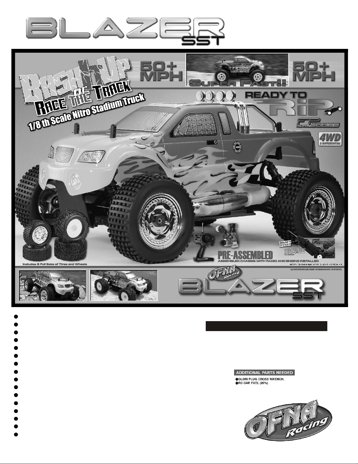
Strong Front and Rear chassis braces.
Tuned Polished Dual Chamber racing pipe.
Unique adjustable chassis width of 310mm or 330mm.
High performance .26 engine with Shaft Start Motor handle.
Full race Offset King Pin aluminum steering knuckle.
Three sealed differentials with 6 steel gears.
Racing Stadium and Truck tire sets.
Adjustable Front and Rear roll bars.
Multi disc brakes with adjustable bias.
Hard Coated Threaded body oil fill shocks.
5 Degree hard coated 3mm chassis.
Racing 3 shoe clutch with Aluminum CNC flywheel.
Steel main spur gear and center differential.
Adjustable servo saver.
Front CVA joint and 8mm axles.
140+cc fuel tank with inside stone filter.
INSTRUCTION MANUAL
RTR KITS - REQUIRED FOR OPERATION
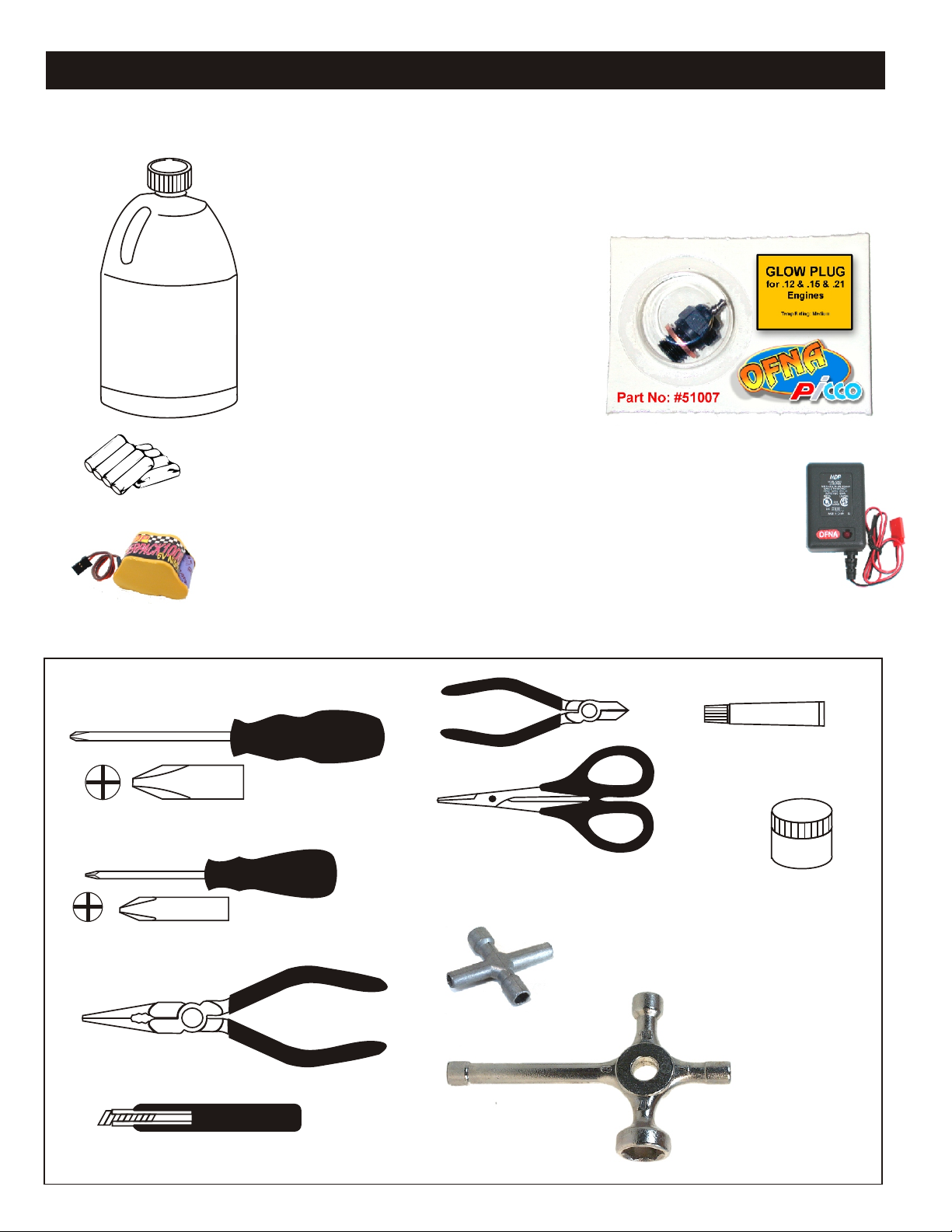
THINGS NEEDED
Glow Fuel
20%
AA Batteries ( 12 pcs )
You will need to buy a few items to start the engine and run the car.
• Use 20% nitro CAR fuel. Do not use airplane or heli fuels, they will
over heat engine.
• Buy LONG glow plugs, like OFNA/PICCO Plug (#51007 or 51008).
Use plugs without idle bar. Do NOT use plugs, like the MC-59 or OS-8
In your box you will find..
• #10163 - Bottle, spout top
• #10219 - Red “D” size glow heater
You need to get batteries for the radio transmitter and the car receiver packs.
• Radio TX needs (8) eight AA batteries.
• Car needs (4) four AA Ni-cad batteries 2000Mah OFNA #10196 or (4) Alkaline.,
Alkaline type batteries will work, but braking will be reduced and 30 minute life. The
best for car, is to use a 5 cell hump receiver pack for increased voltage and longer
life..
Recommended Option:
You may want to upgrade the car battery pack to a Ni-Cad or NiHm 5 cell
type(600AE). This will give more run time. OFNA #10212 1200NiMh Hump Pack and
#10212 NiHm Hump Pack,
see charger 10214.
NiHm Battery Charger #10214
TOOLS NOT INCLUDED IN KIT,
BUT NEEDED TO MAINTAIN YOUR CAR.
Phillips Type Screw Drivers ( L )
Phillips Type Screw Drivers ( S )
10214
Over-nite
Charger
Instant Cement
Cutter
Curved Scissors
#91009 $5.95
Grease
Cross Wrench
#17109 $3.95
Needle Nose Pliers
Knife
Glow Plug & 17MM Cross Wrench
#10801 $6.95

MUST READ THIS BEFORE RUNNING
Running a nitro kit is fun and easy, but to make this a safe • Clean oil and dirt from chassis with a degreaser.
and good experience you must observe a few rules. This
kit is extremely fast, easily over 40MPH, and can seriously
injure someone if you are not careful.
Where to run car?
• Any running area you choose must be dry. Do not run
car near any water or wet dirt.
• Do not run on public streets. It is very easy to have the
car run over or damaged by hitting the curb.
• Do not operate car in tight confined places. The car is
very fast and will easily hit something.
• Do not run near people or animals.
and will too easily hit someone.
• Due noise, you will want to consider the surrounding
area when operating the car.
• Do not operate the car at night. You will not be able to
drive it without hitting something.
• Do not operate the car indoors. Engine exhaust is not
healthy.
Glow Fuel
• Glow fuel is poisonous!
• Glow fuel is flammable! label for additional precautions.
• Do not leave in fuel bottle with lid off at any time.
• Do not use any fuel other than glow fuel in this engine. • Car Fuel tank - Never store fuel in car tank, it will ruin the
First Time Starting the Engine
Caution! When starting engine make sure the following is
observed.
• Set engine Master needle to 3 turns (rich setting) • DAMAGE DUE CAR RUN AWAY IS NOT A WARRANTY
• Do not do this alone, get an experienced friend to help at
first.
• Fill fuel tank, try not to spill fuel. Do not spill fuel on
receiver
• Hold car off the ground, so it will not runaway when first
starts
• Turn on Radio and check the linkage before starting
engine.
• Turn on car receiver battery switch.
• Always have an air filter on the carburetor to keep dirt
out.
The car is very fast
Precautions
• This kit is not a toy. Always run car with a second
person as a spotter and pitman.
• Hot Parts - The pipe, manifold, engine and head are very
hot and will cause burns.
• Rotating Parts - Keep hands away from the drive train,
wheels, and engine when engine is running.
• Radio - Check batteries life before running the car. If
radio does not have full control of the car with steering
and/or throttle/brake do not run until corrected. Failure to
correct this will result in possible injury and damage to the
car or property.
• Glow fuel - Do leave the glow fuel unattended with the lid
off. Fuel contains Methanol and Nitro Methane and is
flammable and poisonous.
Store fuel in cool ventilated location. Refer the glow fuel
engine if left in tank.
• Always turn off the car BEFORE turning off radio.
ISSUE.
IF YOU DO NOT BREAK-IN ENGINE
CORRECTLY, MAINLY AT LOW RPM,
YOU WILL BREAK THE CONNECTING
ROD!
FAILURE TO NOT READ AND
Engine Break-in
• See Engine Page.
Emergency Stopping Engine When Running
• Remove air filter and cover carb. intake.
• Squeeze fuel line and hold until engine stops.
• With a rag, cover exhaust outlet.
Storing Car After Running
• Remove fuel from tank and fuel lines
• Turn off radio in car
• Put a few drops of after run in engine to keep it from
rusting.
FOLLOW BREAK-IN ENGINE
INSTRUCTIONS WILL VOID
WARRANTY!
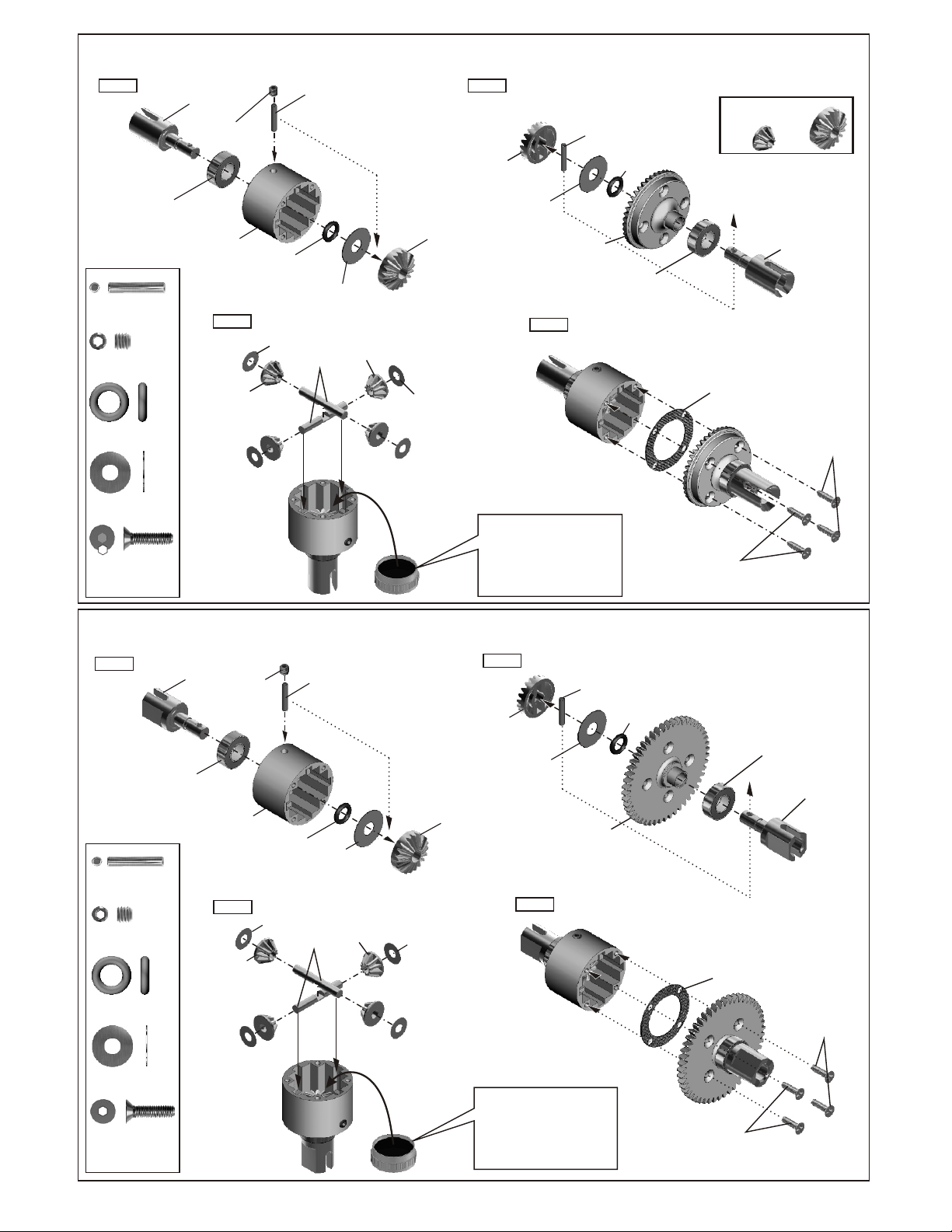
ASSEMBLE OF THE DIFFERENTIAL FOR FRONT AND REAR
40010
40009
P6 O-Ring
30779
4x10mm
Washer
2.5x13.8mm
Pin
40012
6x18mm
Washer
30773
4mm
Cross Pin
40004
Diff. Gear
(Small)
40004
Diff. Gear
(Large)
30779
4x10mm
Washer
Step 2
40004
Diff. Gear
(Large)
Step 1
40010
2.5x13.8mm
Pin
94034
4x4mm
Set Screw
40009
P6 O-Ring
40006
Cap Joint
36053
8x16mm
Ball bearing
..........X2
..........X1
..........X2
94034
4x4mm
Set Screw
40003
Diff. Case
Step 3
40004
Diff. Gear
(Small)
40012
6x18mm
Washer
Step 4
40010
2.5x13.8mm
Pin
49032
Large
Bevel Gear
40009
P6
O-Ring
36053
8x16mm
Ball bearing
Builds two differentials for front and rear.
OPT :
JS-01
CNC Steel Diff. Gear Set
40006
Cap Joint
40011
Diff. Gasket
94020
3x12mm
Flat Head
Hex Screw
30779
4x10mm
Washer
94020
3x12mm
Flat Head
Hex Screw
..........X4
..........X4
ASSEMBLY OF THE DIFFERENTIAL FOR CENTER
Step 1
40010
2.5x13.8mm
Pin
94034
4x4mm
Set Screw
40009
P6 O-Ring
..........X2
..........X1
..........X2
40005
Break
Cap Joint
36053
8x16mm
Ball bearing
4x4mm
Set Screw
40003
Diff. Case
Step 3
40004
Diff. Gear
(Small)
94034
40009
O-Ring
30779
4x10mm
Washer
40010
2.5x13.8mm
Pin
40012
6x18mm
Washer
30773
4mm
Cross Pin
40004
Diff. Gear
(Small)
30779
4x10mm
Washer
40004
Diff0. Gear
(Large)
Apply diff. Gear grease to the
differential during assembly.
Fill the diff. case to
approx 70% with grease.
Step 2
40010
2.5x13.8mm
Pin
40004
Diff. Gear
(Large)
40012
6x18mm
Washer
49016
Spur Gear
Step 4
40009
O-Ring
94020
3x12mm
Flat Head
Hex Screw
40011
Diff. Gasket
36053
8x16mm
Ball bearing
40005
Break
Cap Joint
94020
Flat Head
Hex Screw
30779
4x10mm
Washer
94020
3x12mm
Flat Head
Hex Screw
..........X4
..........X4
Apply diff. Gear grease to the
differential during assembly.
Fill the diff. case to
approx 70% with grease.
94020
3x12mm
Flat Head
Hex Screw
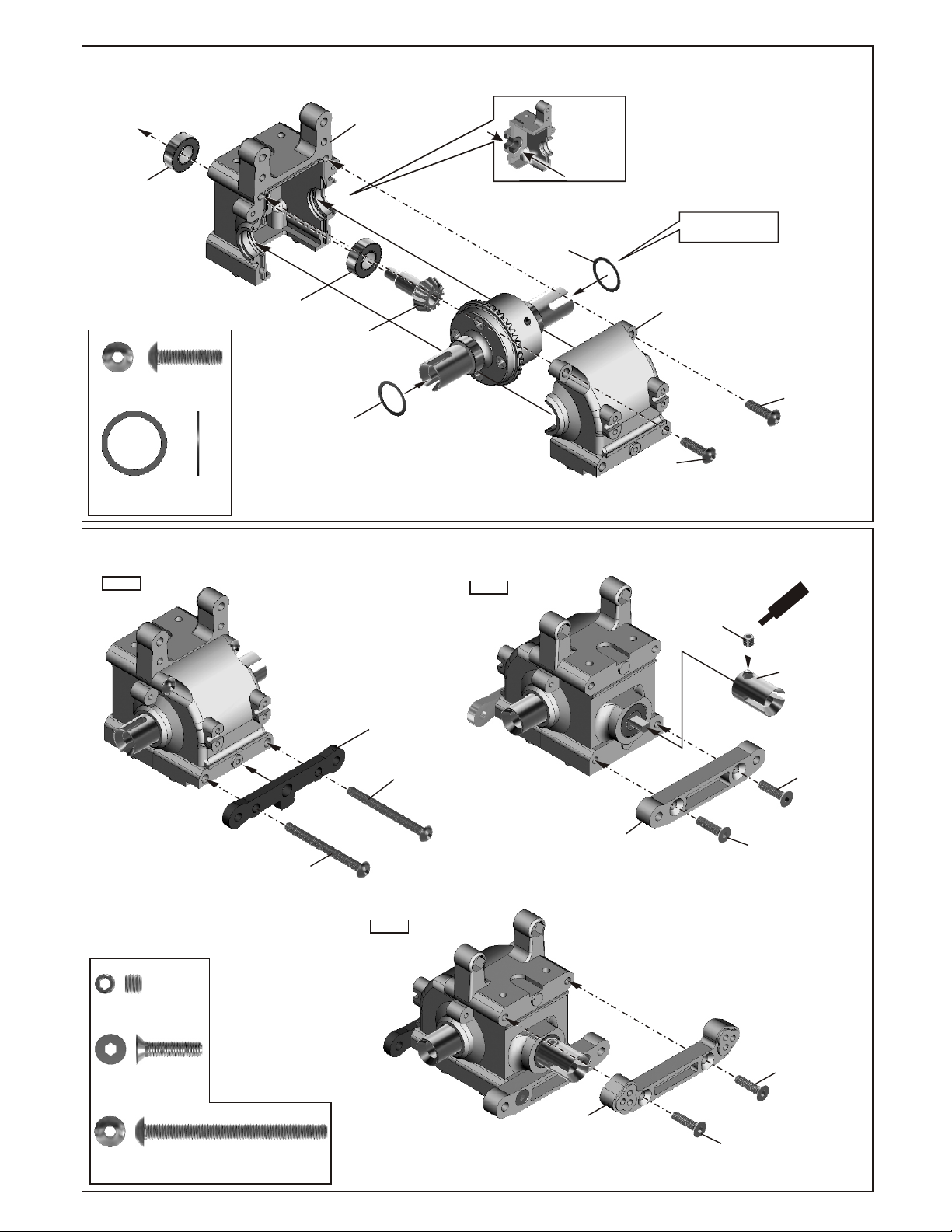
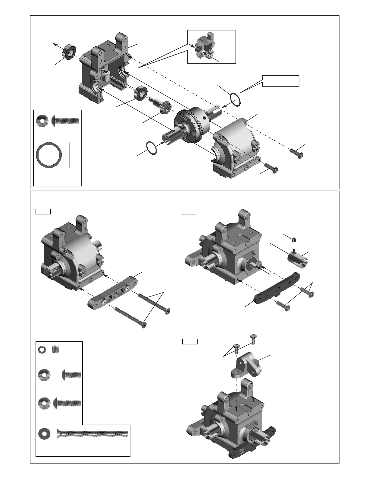
ASSEMBLY OF THE FRONT GEAR BOX
40017
Gear Box
36053
8X16mm
Ball bearing
36053
8X16mm
94011
4x16mm
Hex Screw
40024
13x16x0.2mm
Shim
Ball bearing
..........X2
..........X2
49012
Small
Bevel Gear
40024
13x16x0.2mm
Shim
ASSEMBLY OF THE FRONT ARMS HOLDER
Insert two ball
bearings as
shown.
40024
13x16x0.2mm
Shim
Adjust the backlash
with the shims.
40017
Gear Box
94011
4x16mm
Hex Screw
94011
4x16mm
Hex Screw
Step 1
90026
5x4mm
Set Screw
94027
4x16mm
Flat Head
Hex Screw
94014
4x45mm
Hex Screw
..........X1
..........X4
..........X2
94014
4x45mm
Hex Screw
40022
Front Lower Arm
Holder
94014
4x45mm
Hex Screw
Step 3
Step 2
40015
Front Lower arm
Holder (Rear/Plastic)
40015
Front Upper arm
Holder (Rear/Plastic)
90026
5x4mm
Set Screw
94027
4x16mm
Flat Head
Hex Screw
c
S
C
36730
Cap Joint
94027
4x16mm
Flat Head
Hex Screw
94027
4x16mm
Flat Head
Hex Screw
t
w
n
e
e
r
m
e
94027
4x16mm
Flat Head
Hex Screw

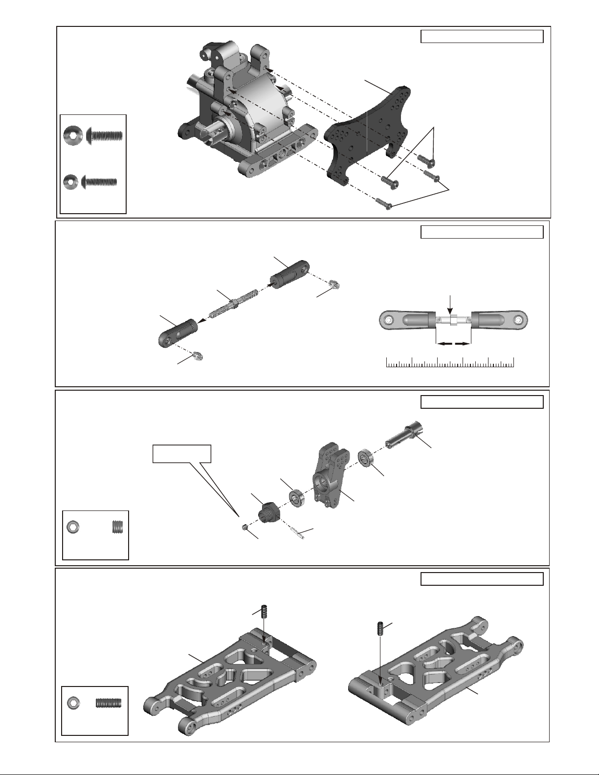
ASSEMBLY OF THE FRONT SHOCK STAY
94010
4x12mm
Hex Screw
..........X2
40116
Shock Tower
94010
4x12mm
Hex Screw
94010
3x12mm
Hex Screw
..........X2
ASSEMBLY OF THE FRONT UPPER ARMS
40104
36860
10mm
Ball and Socket
5x35mmTurnbuckle¡@
..........X2
36860
5x35mm
Turnbuckle
40101
Front Upper
Arm Ball End
ASSEMBLY OF THE KNUCKLE ARMS
36055
2.5x17mm
Pin
90026
5x4mm
Set Screw
36054
Alum.
Wheel Hub 8mm
S re
c
C
e
w
m
e
n
t
..........X2
..........X2
36053
8x16x5mm
Ball bearing
90026
5x4mm
Set Screw
"R" for right hand side.
40103
Alloy Front
Knuckle Arm
(Right)
36055
2.5x17mm
Pin
36053
8x16x5mm
Ball bearing
40101
Front Upper
Arm (Left)
40105
8mm CVD Joint
(Front)
94010
4x12mm
Hex Screw
40101
Front Upper
Arm (Right)
40101
Front Upper
Arm Ball End
36860
5x35mm
Turnbuckle
"L" for Left hand side.
40105
8mm CVD Joint
(Front)
36053
8x16x5mm
Ball bearing
36053
8x16x5mm
Ball bearing
94004
3x12mm
Hex Screw
40104
10mm
Ball and Socket
36054
Alum.
Wheel Hub 8mm
40103
Alloy Front
Knuckle Arm
(Left)
¡¯Approx 6mm
36055
2.5x17mm
Pin
t
w
e
en
cr
em
S
C
90026
5x4mm
Set Screw
ASSEMBLY OF THE FRONT LOWER ARMS
4x10mm
Set Screw
40104
10mm
Ball and Socket
36870
4x10mm
Set Screw
..........X2
40102
Front Lower Arm-L
36870
*A 4x10mm set screw is
used to adjust the ride
height.
*A 4x10mm set screw is
used to adjust the ride
height.
40104
10mm
Ball and Socket
36870
4x10mm
Set Screw
40102
Front Lower Arm-R
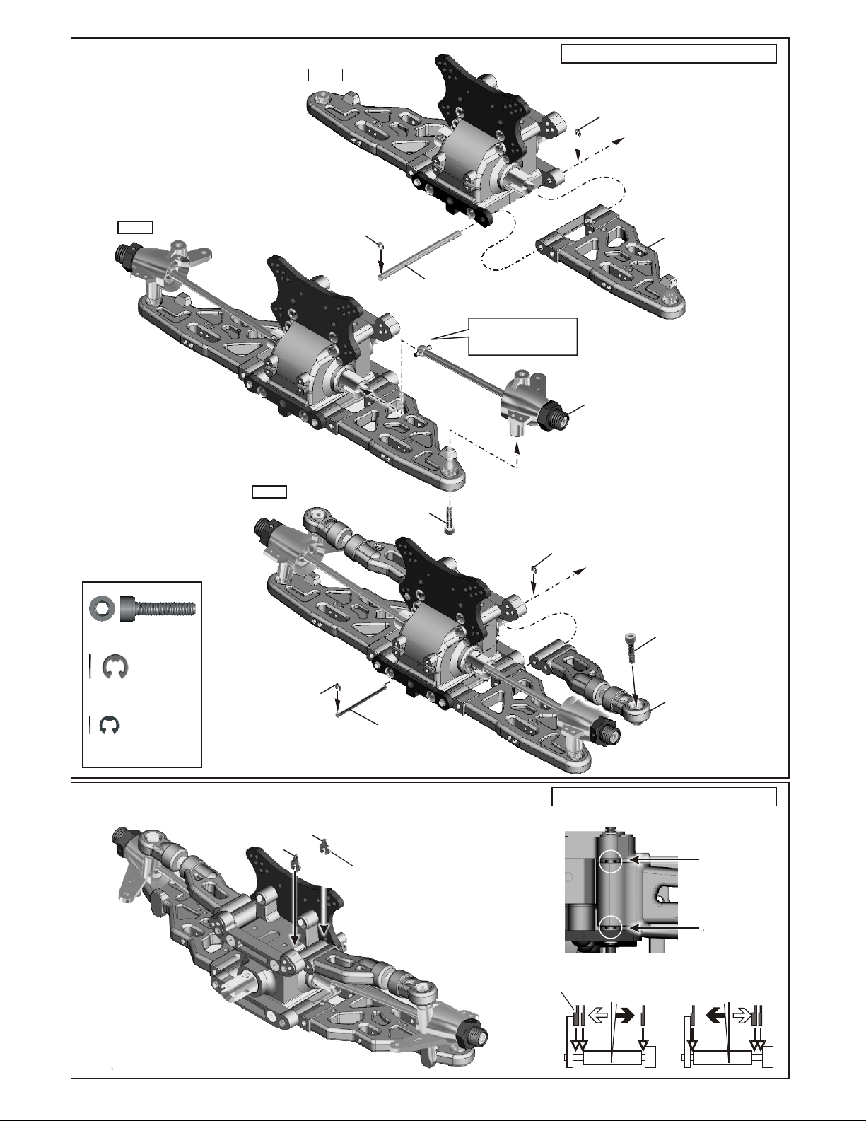
ASSEMBLY OF THE FRONT SUSPENSION ARMS
Step 1
Assembly of the right and left hand side are the same.
90021
E-Ring
40104
4x16mm
Cap Screw
Step 2
..........X4
Step 3
90021
E-Ring
40104
4x16mm
Cap Screw
40023
Lower Arm
Shaft (4mm)
Insert the rear drive shaft into
cap joint before assembly
the rear lower arm.
90020
2.5mm
E-Ring
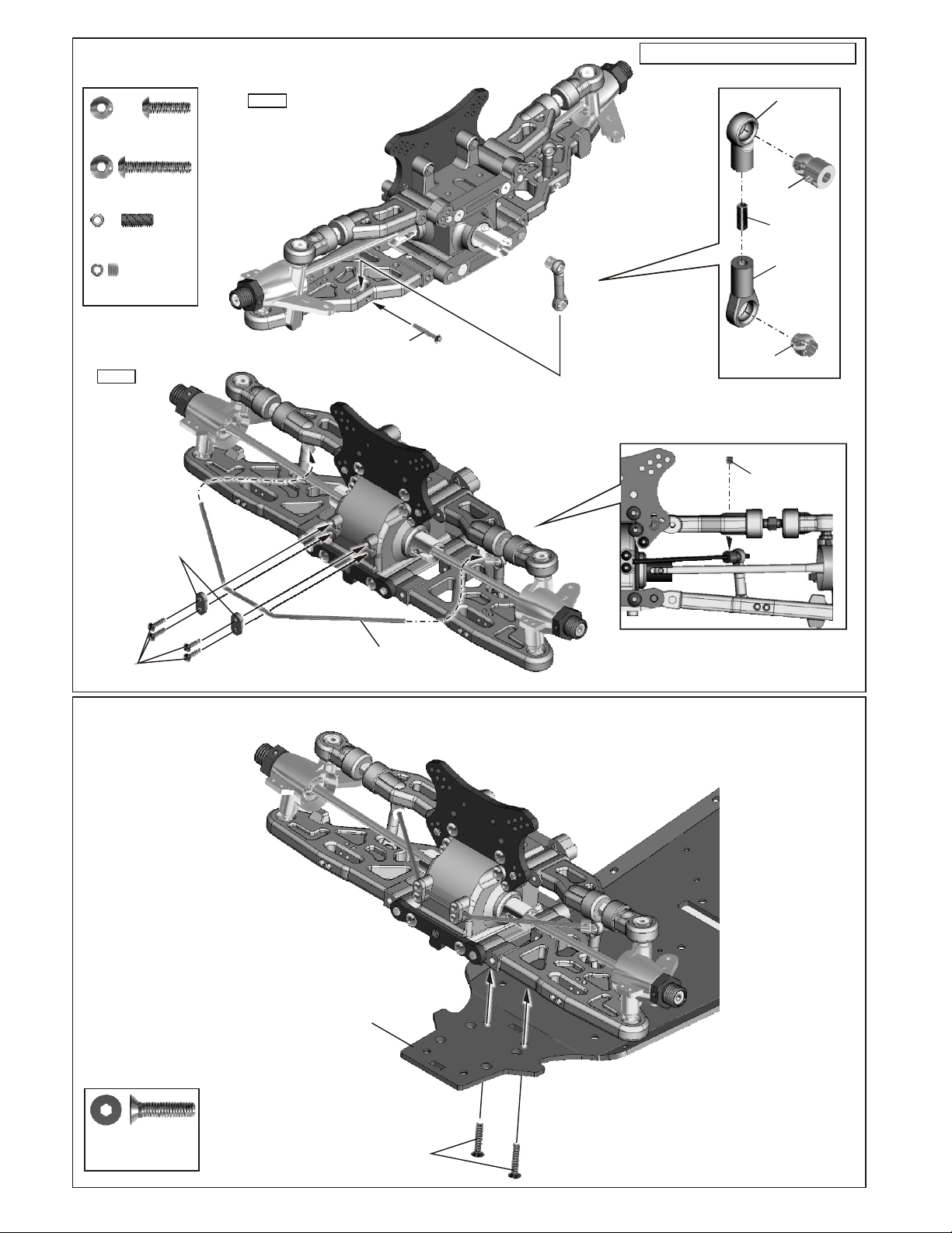
ASSEMBLY OF THE
FRONT KNUCKLE ARMS
40104
4x16mm
Cap Screw
ASSEMBLY OF THE
FRONT LOWER ARMS
90021
3mm
E-Ring
90020
2.5mm
E-Ring
..........X4
..........X4
CLIP IN THE CASTER ADJUSTER
B
90020
2.5mm
E-Ring
A
36170
Arm Shaft
3mm
40101
Caster Adjuster
ASSEMBLY OF THE
FRONT LOWER ARMS
Assembly of the right and left hand side are the same.
* Use caster adjuster to change the
caster angle.
Caster Adjuster
Caster angle will
become bigger.
B
A
Caster angle will
become less.
ASSEMBLY OF THE FRONT STABILIZER
Assembly of the right and left hand side are the same.
40290
3x10mm
Hex Screw
94005
3x16mm
Hex Screw
94035
M3x8mm
Set Screw
94033
M3x3
Set Screw
Step 2
..........X4
..........X2
..........X2
..........X2
40290
Stabilizer
Mount Plastic
Step 1
94005
3x16mm
Hex Screw
40029
Stabilizer
Ball End
30341
Stabilizer Ball
94035
3x8mm
Set Screw
40199
Stabilizer
Ball End
30401
6mm
Ball End
94033
M3x3
Set Screw
40019
40290
3x10mm
Hex Screw
Stabilizer
ASSEMBLY OF THE FRONT GEAR BOX ONTO CHASSIS
40064
Chassis
94027
4x16mm
Flat Head
Hex Screw
..........X2
94027
4x16mm
Flat Head
Hex Screw
ASSEMBLY OF THE REAR GEAR BOX
40017
Gear Box
36053
8X16mm
Ball bearing
36053
8X16mm
Ball bearing
49012
94011
4x15mm
Hex Screw
40024
13x16x0.2mm
Shim
..........X2
..........X2
Small
Bevel Gear
40024
13x16x0.2mm
Shim
ASSEMBLY OF THE REAR ARM HOLDER
Step 1 Step 2
Insert two ball
bearings as
shown.
40024
13x16x0.2mm
Shim
40017
Gear Box
94011
4x15mm
Hex Screw
Adjust the backlash
with the shims.
94011
4x15mm
Hex Screw
90026
5x4mm
Set Screw
94009
4x10mm
Hex Screw
..........X1
..........X2
40015
Rear arm Holder
94030
4x45mm
Flat Head
Hex Screw
Step 3
94009
4x10mm
Hex Screw
40025
Rear
Lower Arm Holder
90026
5x4mm
Set Screw
40027
Win Stay
Mount
36730
Cap Joint
94011
4x15mm
Hex Screw
94011
4x15mm
Hex Screw
94030
4x45mm
Flat Head
Hex Screw
..........X2
..........X2
ASSEMBLY OF THE REAR SHOCK STAY
94010
4x12mm
Hex Screw
94004
3x12mm
Hex Screw
..........X2
..........X2
40116
Shock Tower
Assembly of the right and left hand side are the same.
94010
4x12mm
Hex Screw
94004
3x12mm
Hex Screw
ASSEMBLY OF THE UPPER ARM ROD
* Builds two upper arms for left and right hand-side.
36860
5x60mm
Turnbuckle
40065
Upper arm
Plastic Rod End
36850
7mm Ball
ASSEMBLY OF THE REAR WHEEL HUB
*Builds two rear wheel hubs for use.
Do not tighten
set screw over tighten.
36054
Alum.
Wheel Hub 8mm
90026
5x4mm
Set screw
..........X2
40065
Upper arm
Plastic Rod End
36053
8x16x5mm
Ball Bearings
90026
5X4mm
Set Screw
36850
7mm Ball
36055
2.5x16.8mm
Pin
36081
Wheel
Rear Hub
Assembly of the right and left hand side are the same.
* Anticlockwise mark.
26mm
0 10 20 30 40 50
Assembly of the right and left hand side are the same.
36082
Rear Wheel
Axle Shaft
36053
8x16x5mm
Ball Bearings
mm
ASSEMBLY OF THE FRONT LOWER ARMS
36870
4x10mm
Set Screw
40102
Rear Lower Arm
36870
4x10mm
Set Screw
..........X2
* A 4x10mm set screw is
used to adjust the ride
height.
36870
4x10mm
Set Screw
Assembly of the right and left hand side are the same.
40102
Rear Lower Arm
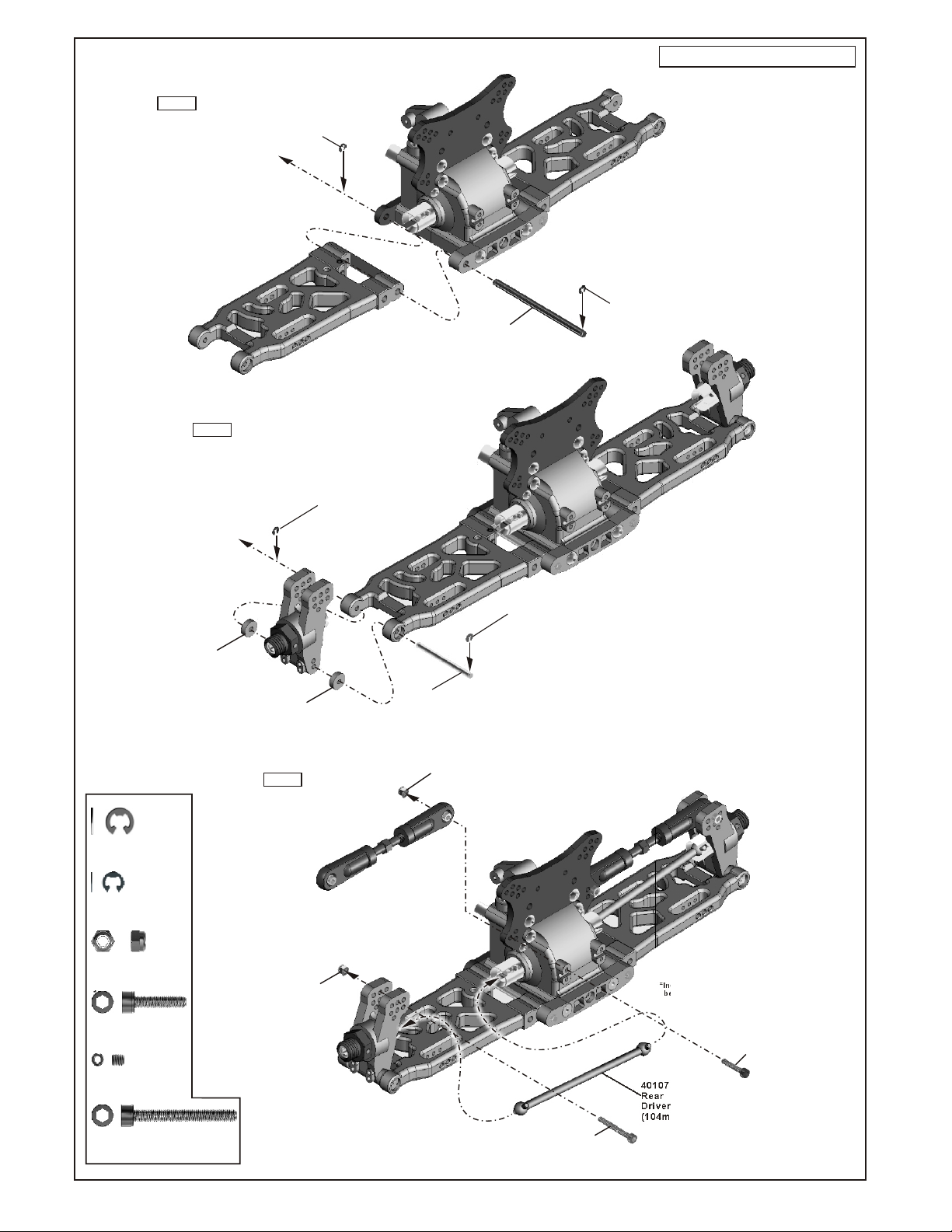
ASSEMBLY OF THE REAR SUSPENSION ARMS
Assembly of the right and left hand side are the same.
Step 1
Step 2
90021
3.0mm
E-Ring
2.5mm
E-Ring
90020
40023
4mm
Lower Arm Shaft
90021
3.0mm
E-Ring
90021
3mm
E-Ring
90020
2.5mm
E-Ring
35313
M3
Nylon Nut
94007
3X16mm
Cap Screw
M3x3
Set Screw
90018
3X25mm
Cap Screw
..........X4
..........X2
..........X2
..........X2
..........X2
..........X2
40102
3mm
Plastic Washer
40102
3mm
Plastic Washer
Step 3
35313
Nylon Nut
36170
3mm Arm Shaft
35313
Nylon Nut
90020
2.5mm
E-Ring
90018
3X25mm
Cap Screw
*Insert the rear drive shaft
before assembly.
40107
Rear
Driver Shaft
(104mm)
94007
3X16mm
Cap Screw
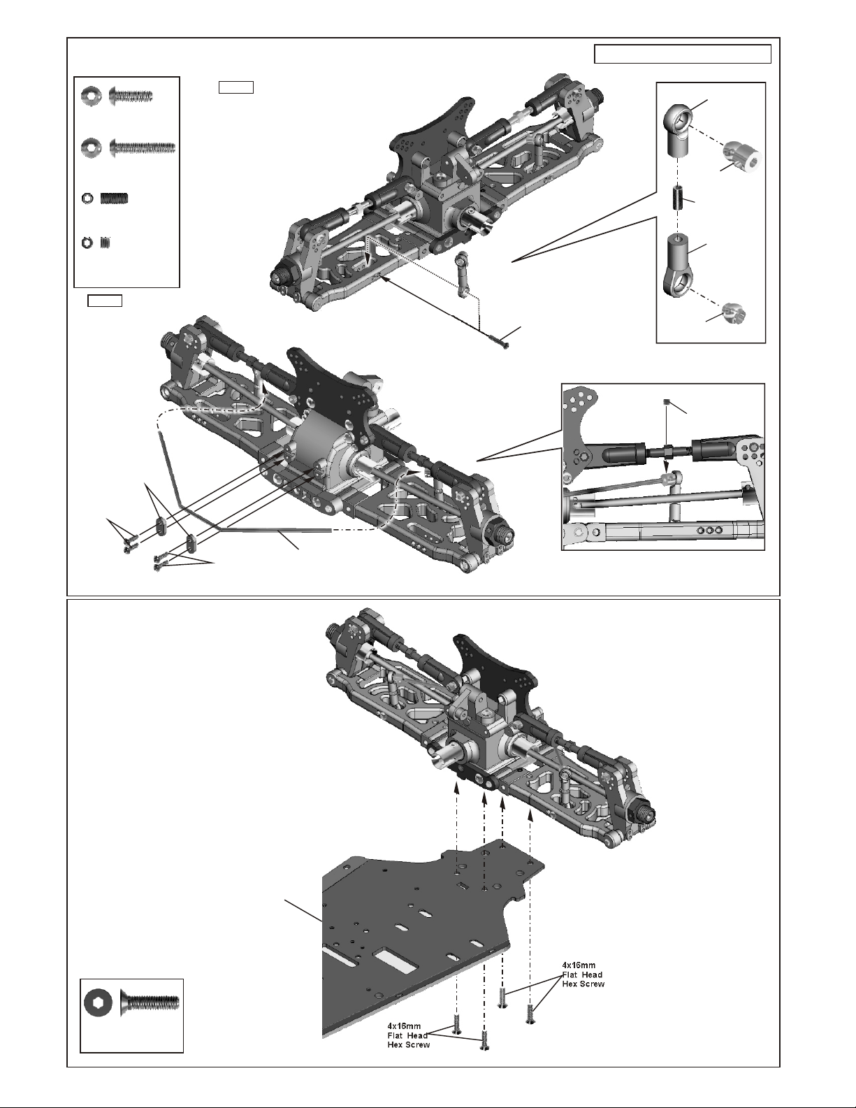
ASSEMBLY OF THE REAR STABILIZER
Assembly of the right and left hand side are the same.
40290
3x10mm
Hex Screw
94005
3x16mm
Hex Screw
94035
M3x8mm
Set Screw
94033
M3x3
Set Screw
Step 2
40290
3x10mm
Hex Screw
..........X4
..........X2
..........X2
..........X2
40290
Stabilizer
Mount Plastic
Step 1
94005
3x16mm
Hex Screw
40029
Stabilizer
Ball End
30341
Stabilizer Ball
94035
3x8mm
Set Screw
40199
Stabilizer
Ball End
30401
6mm
Ball End
94033
M3x3
Set Screw
40290
3x10mm
Hex Screw
ASSEMBLY OF THE REAR GEAR
BOX ONTO CHASSIS
40064
Chassis
40019
Stabilizer
94027
4x16mm
Flat Head
Hex Screw
..........X4
94027
4x16mm
Flat Head
Hex Screw
94027
4x16mm
Flat Head
Hex Screw
 Loading...