


RTR Instruction
Manual
OFNA Racing
22692 Granite Way, Ste. B
Laguna Hills, Ca. 92653
(949) 586-2910
Www.ofna.com
RTR KITS - REQUIRED FOR OPERATION
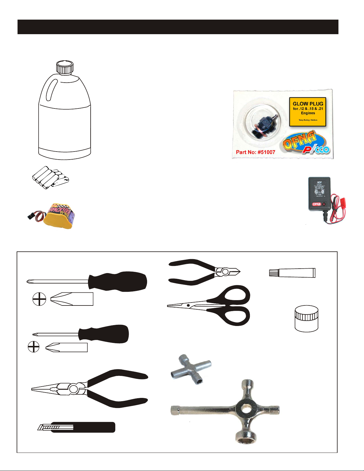
THINGS NEEDED
Glow Fuel
20%
AA Batteries ( 12 pcs )
You will need to buy a few items to start the engine and run the car.
• Use 20% nitro CAR fuel. Do not use airplane or heli fuels, they will
over heat engine.
• Buy LONG glow plugs, like OFNA/PICCO Plug (#51007). Use plugs
without idle bar. Do NOT use plugs, like the MC-59 or OS-8
In your box you will find..
• #10163 - Bottle, spout top
• #10218 - Red “C” size glow heater
You need to get batteries for the radio transmitter and the car receiver packs.
• Radio TX needs (8) eight AA batteries.
• Car needs (4) four AA Ni-cad batteries 2000Mah OFNA #10196 or (4) Alkaline.,
Alkaline type batteries will work, but braking will be reduced and 30 minute life. The
best for car, is to use a 5 cell hump receiver pack for increased voltage and longer
life..
Recommended Option:
You may want to upgrade the car battery pack to a Ni-Cad or NiHm 5 cell
type(600AE). This will give more run time. OFNA #10212 1000NiMh Hump Pack and
#10212 NiHm Hump Pack,
see charger 10214.
NiHm Battery Charger #10214
TOOLS NOT INCLUDED IN KIT,
BUT NEEDED TO MAINTAIN YOUR CAR.
Phillips Type Screw Drivers ( L )
Phillips Type Screw Drivers ( S )
10214
Over-nite
Charger
Instant Cement
Cutter
Curved Scissors
#91009 $5.95
Grease
Cross Wrench
#17109 $3.95
Needle Nose Pliers
Knife
Glow Plug & 17MM Cross Wrench
#10801 $6.95

MUST READ THIS BEFORE RUNNING
Running a nitro kit is fun and easy, but to make this a safe • Clean oil and dirt from chassis with a degreaser.
and good experience you must observe a few rules. This
kit is extremely fast, easily over 40MPH, and can seriously
injure someone if you are not careful.
Where to run car?
• Any running area you choose must be dry. Do not run
car near any water or wet dirt.
• Do not run on public streets. It is very easy to have the
car run over or damaged by hitting the curb.
• Do not operate car in tight confined places. The car is
very fast and will easily hit something.
• Do not run near people or animals.
and will too easily hit someone.
• Due noise, you will want to consider the surrounding
area when operating the car.
• Do not operate the car at night. You will not be able to
drive it without hitting something.
• Do not operate the car indoors. Engine exhaust is not
healthy.
Glow Fuel
• Glow fuel is poisonous!
• Glow fuel is flammable! label for additional precautions.
• Do not leave in fuel bottle with lid off at any time.
• Do not use any fuel other than glow fuel in this engine. • Car Fuel tank - Never store fuel in car tank, it will ruin the
First Time Starting the Engine
Caution! When starting engine make sure the following is
observed.
• Set engine Master needle to 3 turns (rich setting) • DAMAGE DUE CAR RUN AWAY IS NOT A WARRANTY
• Do not do this alone, get an experienced friend to help at
first.
• Fill fuel tank, try not to spill fuel. Do not spill fuel on
receiver
• Hold car off the ground, so it will not runaway when first
starts
• Turn on Radio and check the linkage before starting
engine.
• Turn on car receiver battery switch.
• Always have an air filter on the carburetor to keep dirt
out.
The car is very fast
Precautions
• This kit is not a toy. Always run car with a second
person as a spotter and pitman.
• Hot Parts - The pipe, manifold, engine and head are very
hot and will cause burns.
• Rotating Parts - Keep hands away from the drive train,
wheels, and engine when engine is running.
• Radio - Check batteries life before running the car. If
radio does not have full control of the car with steering
and/or throttle/brake do not run until corrected. Failure to
correct this will result in possible injury and damage to the
car or property.
• Glow fuel - Do leave the glow fuel unattended with the lid
off. Fuel contains Methanol and Nitro Methane and is
flammable and poisonous.
Store fuel in cool ventilated location. Refer the glow fuel
engine if left in tank.
• Always turn off the car BEFORE turning off radio.
ISSUE.
IF YOU DO NOT BREAK-IN ENGINE
CORRECTLY, MAINLY AT LOW RPM,
YOU WILL BREAK THE CONNECTING
ROD!
FAILURE TO NOT READ AND
Engine Break-in
• See Engine Page.
Emergency Stopping Engine When Running
• Remove air filter and cover carb. intake.
• Squeeze fuel line and hold until engine stops.
• With a rag, cover exhaust outlet.
Storing Car After Running
• Remove fuel from tank and fuel lines
• Turn off radio in car
• Put a few drops of after run in engine to keep it from
rusting.
FOLLOW BREAK-IN ENGINE
INSTRUCTIONS WILL VOID
WARRANTY!
CHECK RADIO SETTING,
LINKAGE AND SET FAIL SAFE
BEFORE STARTING.
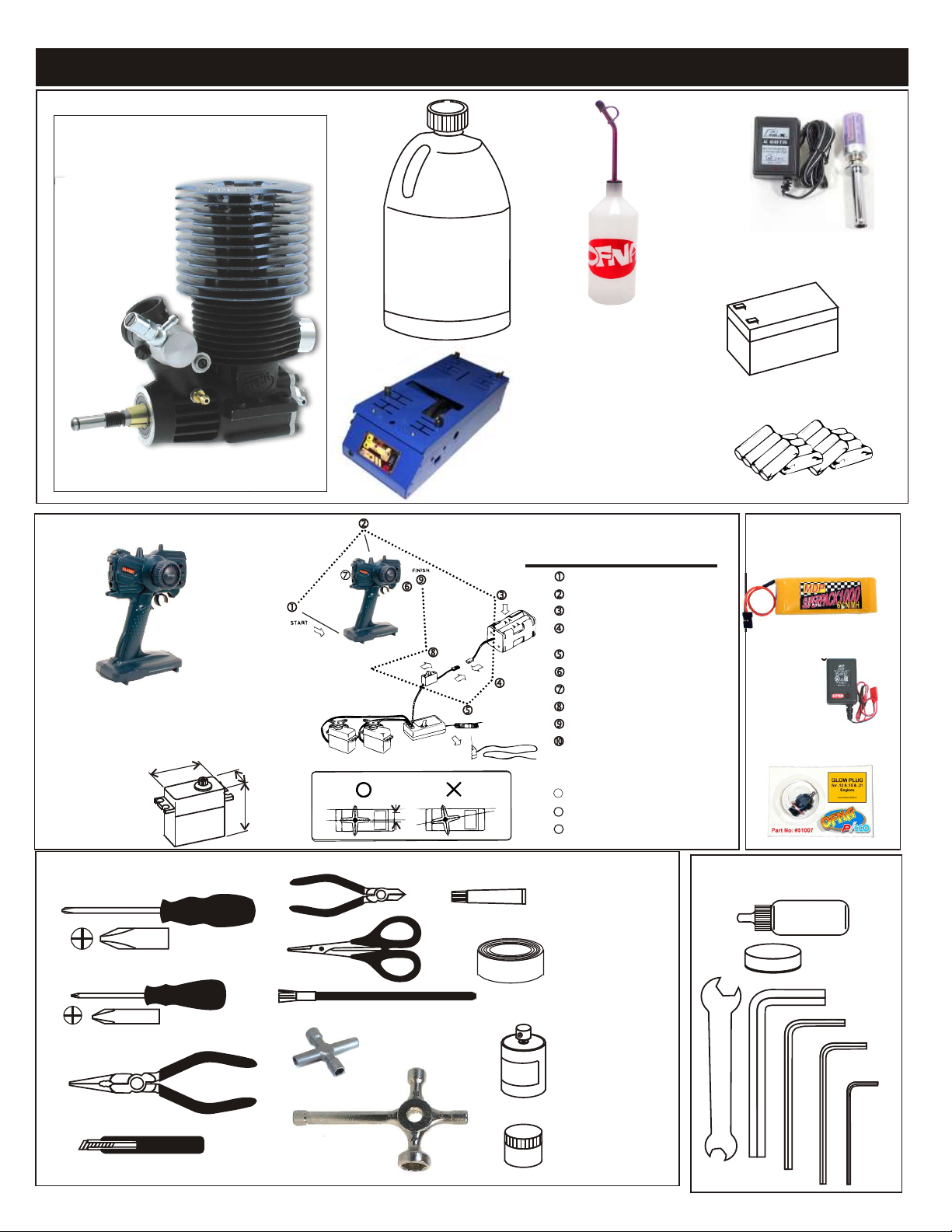
NON-RTR OR PRO KITS - REQUIRED FOR OPERATION
THINGS NEED BESIDES THE KIT
3.5 cc (21 Class) ENGINE
REAR EXHAUST
OFNA/Picco
O-1 bp
#51217
Glow Fuel
20%
Bottle’s with spout
# 10160 - large 500cc
# 10161 - large 500 ccAuto Stop
# 10162 - small 250cc
# 10164 - CNC spout 500CC
# 10167 - CNC spout 800CC
Glow Plug Heat with Battery & Charger
# 10227....$$19.95
(please note OFNA Glow Heats available)
Note: Pro kit does not include engine!
RADIO CONTROL UNIT
Note: Carefully read the instruction manual of your
2 channel radio controller before using.
SUITABLE SERVO SIZE
36mm-41mm
15mm - 21mm
29mm - 42mm
Off-Road Starter Box, 12V motor
# 10250 - 1/8 scale Starter Box
# 10253 - 1/8 scale Starter Box w/ Panel
Off-Road Starter Box, two 550 motors
# 10248 - 1/8 scale Starter Box
# 10249 - 1/8 scale Starter Box,RTR
Optional Parts
# 92571 - Power Panel Glow Heater
# 92572 - Cable for Glow Plug
Radio must be set at neutral position
before installing in the kit.
SEQUENCE TO SET NEUTRAL
Install AA batteries in Radio.
Extend the antenna.(Transmitter)
Install batteries into Car receiver .
After installing the battery, connect the
battery box.
Extend the antenna. (Receiver)
Set the trim-lever at center.
Turn on the switch. (Transmitter)
Turn on the switch. (Receiver)
Make sure the servos are in command.
When the operation stick is in neutral,
servo horns must be in neutral as will.
*Adjustment can be made by re installing the servo horn.
Turn off the switch. (Receiver)
1111
Turn off the switch. (Transmitter)
12
Retract the antenna. (Transmitter)
13
12V Battery for Starter Box
(must have)
AA Batteries ( 12 pcs ) for radio
More Optional Parts . . .
#10211 NiHm Battery Flat
Pack .. $29.95
# 10214 NiHm Battery Pack
Charger.. $7.95
# 51007 OFNA/Picoo Glow
Plug .. $4.95
TOOLS NOT INCLUDED IN KIT
Phillips Type Screw Drivers ( L )
Phillips Type Screw Drivers ( S )
Needle Nose Pliers
Knife
Cutter
Curved Scissors
Brush
Glow Plug & 17MM Cross Wrench
#10801 $6.95
Cross Wrench
#17109 $3.95
Instant Cement
Masking Tape
Paints
Grease
7mm and 5.5mm
Hex Wrench
INCLUDED WITH KIT
Shock Oil
Grease Box
5mm
Hex Wrench
3mm
Hex Wrench
2.5mm
Hex Wrench
1.5mm
Hex Wrench
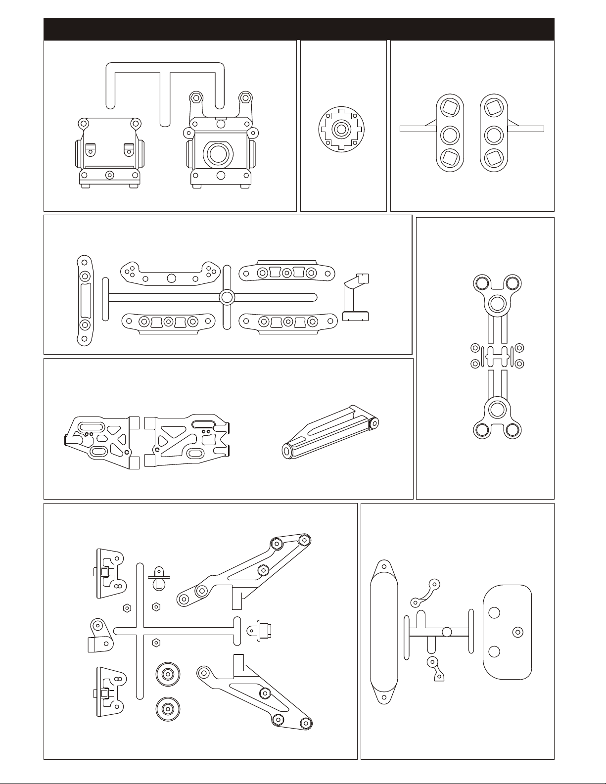
40017
GEAR BOX PLASTIC PARTS
40015
ARM HOLDER PLASTIC PARTS
PLASTIC PARTS
40003
DIFF. CASE
PLASTIC PARTS
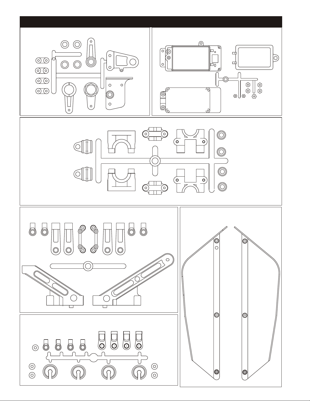
2
36901
Front Knuckles, Pivot Ball
31304
Rear Hub,
Pivot Ball
1
40202
Front and Rear Lower Arms.
40027
WING SUPPORT PLASTIC PARTS
3
40094
Front Upper
MBX Arm
40013 & 40048
FRONT BUMPER & BATTERY HOLDER
PLASTIC PARTS
40031
SERVO SAVER PLASTIC PARTS
40040
CENTER DIFF. MOUNT PLASTIC PARTS
PLASTIC PARTS
40047
RECEIVER BOX PLASTIC PARTS
40018/40029
CHASSIS BRACE PLASTIC PARTS
40056
SHOCK ABSORBER PLASTIC PARTS
40046
STONE GUARD PLASTIC PARTS
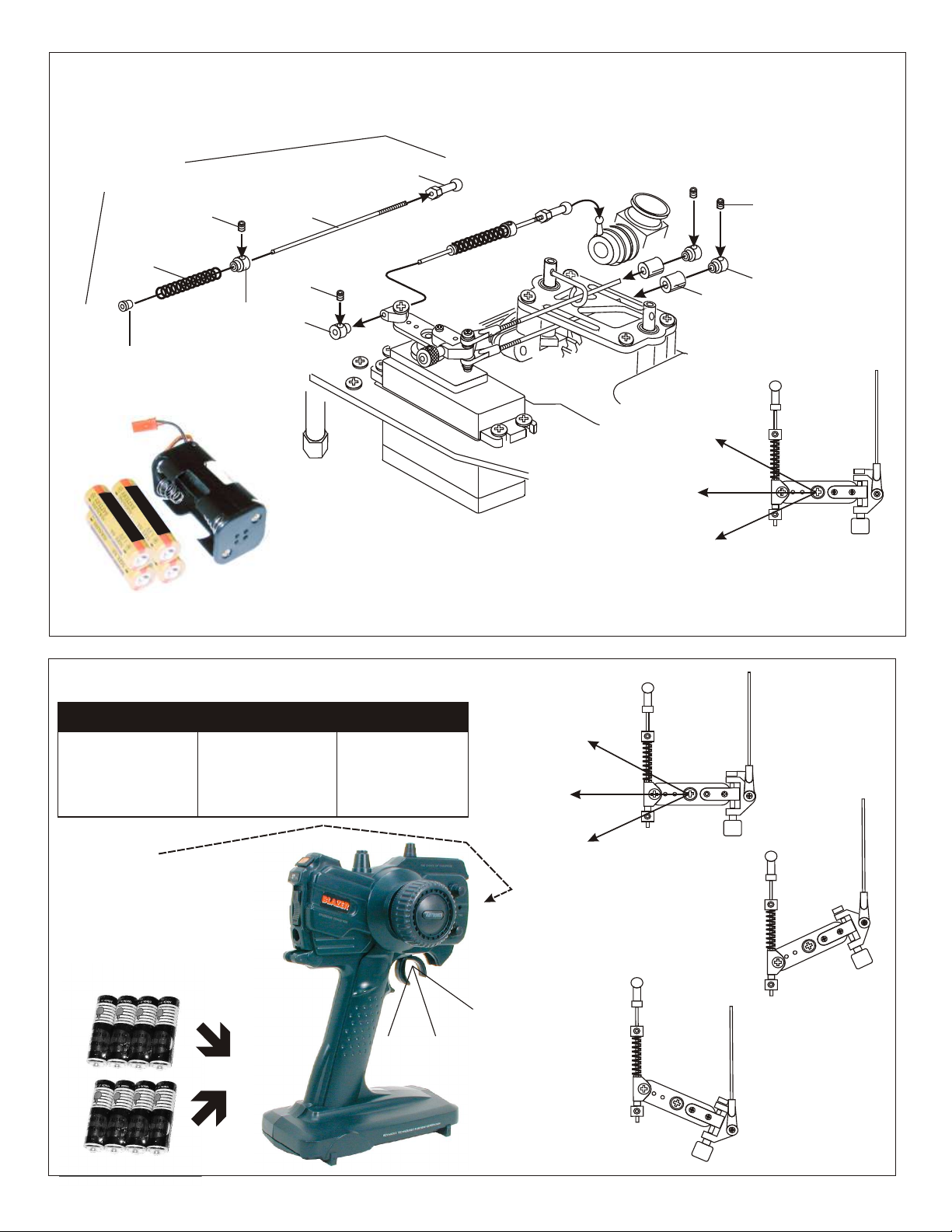
ASSEMBLY OF THE THROTTLE LINKAGE SYSTEM
#30800
Plastic Throttle
kit
Throttle
Spring
Plastic Collar
* Take the plastic collar
from brake system plastic
parts.
3X3mm
Set Screw
#30530
2mm Rod
3X3mm
Set Screw
Plastic Throttle
Ball Joint
* Snap On.
#10300
Alum.Stopper
Note:
Battery life is short when using Alkaline batteries. For safety, we recommend using
Alkaline batteries for only 30 minutes before testing.. Battery strength affects braking
power and radio range. If voltage drops while running the car, you will loose control and
destroy your car! This is NOT covered under warranty.
To increase run time, upgrade receiver battery to a 5-cell hump pack. But, the most
important step you can make, “is to always use fully charged or fresh batteries when
running your car”. Another choice is to use OFNA #10196 2000 mAh NiMh AA batteries in
car and radio.
Brake
Idle Position
Full Throttle
3X3mm
Set Screw
#10300
Alum.Stopper
Fuel
Tube
( 6mm )
* Align throttle servo same
as shown.
CHECKING ENGINE THROTTLE
A
1. Insert AA batteries into
transmitter (8 Pcs).
2.Turn on transmitter.
3.Turn on receiver.
4.Center throttle trims as
shown .
IMPORTANT
CHECK RADIO THROTTLE
AND STEERING SWITCHES
BEFORE RUNNING CAR
* Insert into transmitter.
1. Pull Full Throttle.
B
C
1. Push trigger to full
brake position.
2. Adjust alum. Stopper to
increase or decrease
the brake.
B
A
* Align throttle servo same
as shown.
Brake (C)
A
Idle Position (A)
Full Throttle (B)
• Full throttle arm position.
Spring rod pulls throttle
barrel open and brake
rods release pressure on
brake cams.
C
C
B
• Full brake arm position.
Spring compresses
forward and brake rods
pull brake levers.
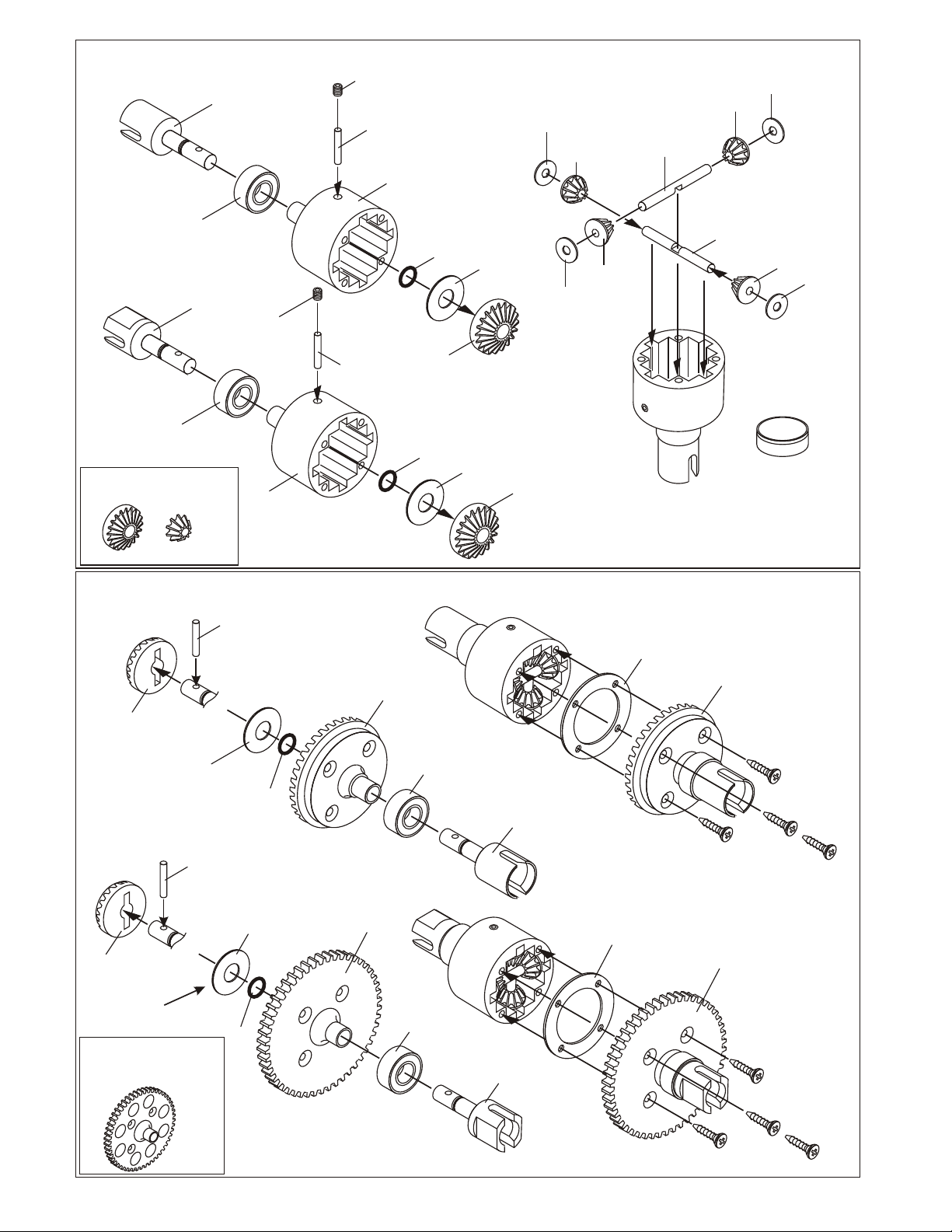
ASSEMBLY OF THE DIFFERENTIAL GEAR
4x4mm
40006
Cap Joint
Set Screw
40010
2.5x13.8mm
Pin
40003
Diff. Case
30779
4 x 10mm
washer
40004
Diff. Gear
(Small)
30773
4mm
Cross pin
40004
Diff. Gear
(Small)
30779
4 x 10mm
washer
36053
8x16mm
Ball bearing
(Builds one differential for Center)
40005
Break
Cap Joint
36053
8x16mm
Ball bearing
OPTION: #49001 HD STEEL GEAR SET,
INSIDE DIFF.
4x4mm
Set Screw
40003
Diff. Case
40010
2.5x13.8mm
Pin
ASSEMBLY OF THE DIFFERENTIAL CASE
40010
2.5x13.8mm
Pin
40004
Diff. Gear
(Large)
40012
6x15mm
Washer
*Use 6x15mm washer
to adjust the gear mesh.
( Builds two differentials for front and rear.)
40009
P6
O-Ring
40002
41T Large
Bevel Gear
40009
P6 O-Ring
40004
Diff. Gear
(Large)
40009
P6
O-Ring
36053
8x16mm
Ball bearing
40012
6x15mm
Washer
40012
6x15mm
Washer
40004
Diff. Gear
(Large)
40006
Cap Joint
30779
4 x 10mm
washer
40004
Diff. Gear
(Small)
40011
Diff. Gasket
30773
4mm
Cross pin
OPTION:
49032
43T Large
Bevel Gear
(must use 13t pinion)
40002
41T Large
Bevel Gear
40004
Diff. Gear
(Small)
30779
4 x 10mm
washer
Note: It is very important to add
or remove the #30779 washer if
the gear mesh is too tight or
too lose.
* Apply diff. gear grease to the
differential during assembly.
* Fill the diff. the case to
approx 70% with grease.
40010
2.5x13.8mm
Pin
40004
Diff. Gear
(Large)
*Use 6x15mm washer
to adjust the gear mesh.
OPTION:
#49016 SPUR GEAR 50T
#49031 SPUR GEAR 50T, HD SPECIAL
(Builds one differential for Center)
40012
6x15mm
Washer
40009
P6
O-Ring
40001
47T
Spur Gear
36053
8x16mm
Ball bearing
40005
Break
Cap Joint
40011
Diff. Gasket
40001
47T
Spur Gear
3x12mm
Flat Head
Tapping Screw
3x12mm
Flat Head
Tapping Screw
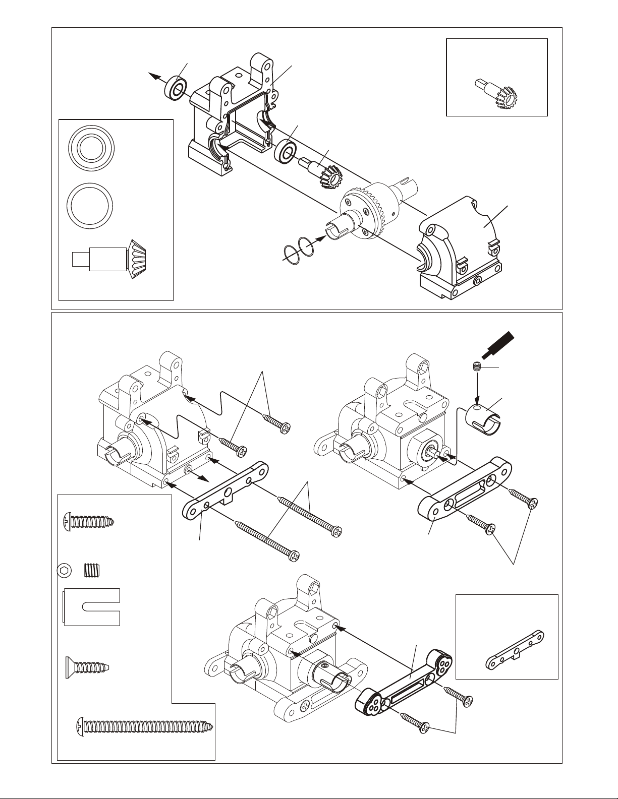
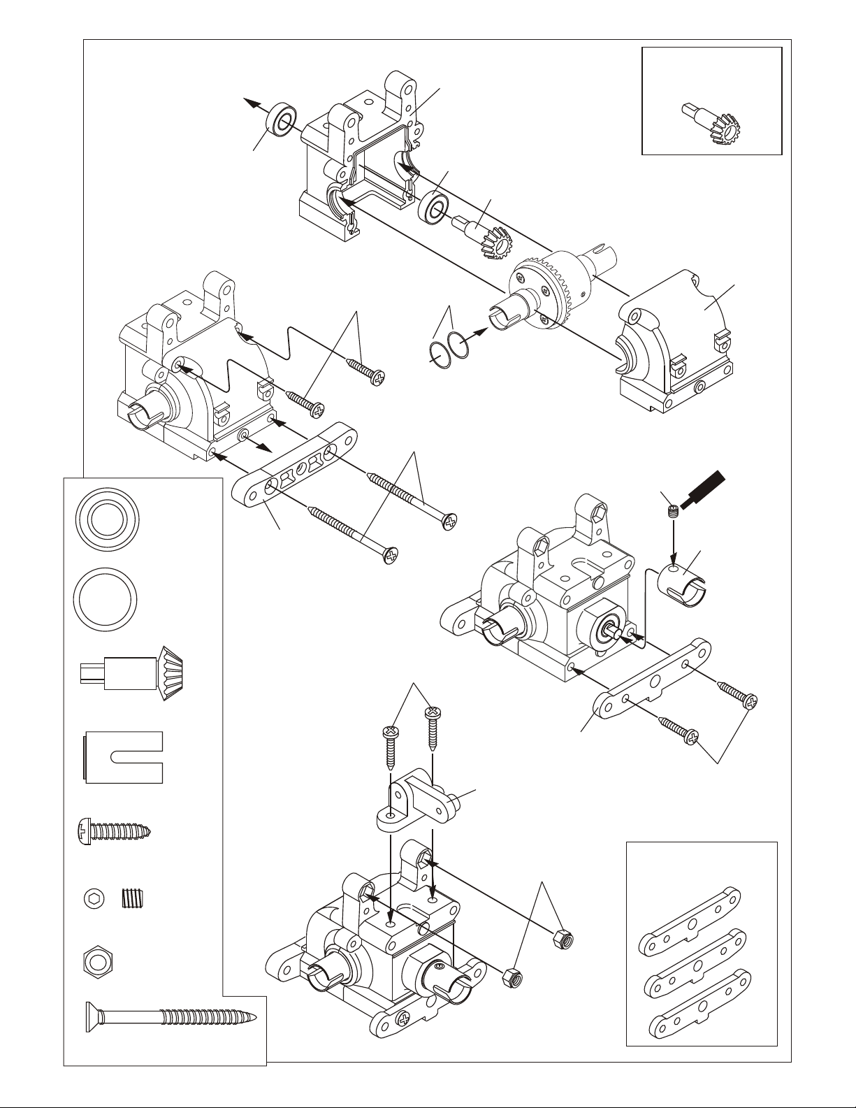
ASSEMBLY OF THE FRONT GEAR BOX
36053
8X16mm
Ball bearing
36053
8X16mm
Ball bearing....4
40024
13x16x0.2mm
Shim..............2
40024
13x16x0.2mm
Shim
40017
Gear Box
36053
8X16mm
Ball bearing
40021
14TSmall
Bevel Gear
OPTION: #49012 PINION GEAR
13TOOTH
40017
Gear Box
40021
14T Small
Bevel Gear..............1
ASSEMBLY OF THE FRONT ARMS HOLDER
4x15mm
Tapping Screw
(Small Head)
MISC. SCREW BAG
40067
4x15mm
Tapping Screw........................2
90026
5x5mm
Set Screw......1
40022
Front Lower Arm
Holder (Front)
Use shims to adjust gear
mesh.
4x45mm
Tapping Screw
(Small Head)
40015
Front Lower arm
Holder (Rear/Plastic)
ment
Screw
Ce
90026
5x5mm
Set Screw
36730
Cap Joint
4x16mm
Flat Head
Tapping Screw
36730
Cap Joint................................1
4 x 16mm
Flat Head
Tapping Screw.......................4
4x45mm
Tapping Screw........................2
40015
Front Upper arm
Holder (Rear/Plastic)
OPTION: #49002 CNC 7075
FRONT LOWER ARM HOLDER
4x16mm
Flat Head
Tapping Screw
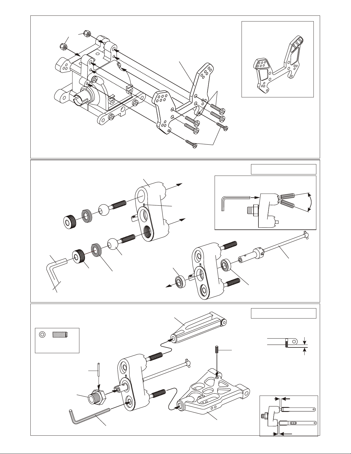
ASSEMBLY OF THE FRONT SHOCK TOWER
35314
4mm
Nylon Nut
36901
ASSEMBLY OF THE FRONT PIVOT
BALL KNUCKLE ARM
Ball Type
Knuckle Arms
( Right and Left Side)
49037
Front
Shock Tower, Orange
40067
M4x15
TP Screw
40067
M3x12
TP Screw
* Adjust alum. nut to
keep steering ball
smooth.
OPT: 49003
CNC 7075 Alum. Shock Tower
Assembly of the right and left hand side
are the same.
* Use 5mm
hex wrench.
36904
14mm
Alum. Nut
36903
14mm
Steering Ball
36905
Steering Ball
Washer
ASSEMBLY OF THE FRONT KNUCKLE ARM
INTO FRONT ARMS
4X10mm
set screw
36055
2.5x17mm
Pin
* Note the "R" mark
is for righthand side.
36053
8x16mm
Ball Bearing
40094
Front Upper
MBX Arm
36870
4x4mm
Set Screw
36052
CVD
Universal Joint
36053
8x16mm
Ball Bearing
Assembly of the right and left hand side
are the same.
* A 4x10mm set screw is used
to adjust the ride-height.
40245
Orange
Wheel Hub
( Alum.)
* Use a 2.5mm
hex wrench.
40202
Front Lower
MBX Arm
3mm
3.5mm
ASSEMBLY OF THE FRONT SUSPENSION ARMS
40023
Lower Arm Shaft (4mm)
90021
3mm
E-Ring
Assembly of the right and left hand side
are the same.
90021
3mm
E-Ring
90020
2.5mm
E-Ring
* Insert the drive shaft into the
cap joint before assembly.
36170
3mm
Arm Shaft
90020
2.5mm
E-Ring
ASSEMBLY OF THE REAR GEAR BOX
36053
8X16mm
Ball bearing
36053
8X16mm
Ball bearing....4
40015
Rear arm Holder
4X16mm
Tapping Screw
(Small Head)
40017
Gear Box
36053
8X16mm
Ball bearing
40024
13x16x0.2mm
Shim
4X45mm
Flat Head
Tapping Screw
40021
14T Pinion
Gear
* Adjust the backlash
with the shims.
OPTION: #49012 PINION GEAR
13TOOTH
90026
5x5mm
Set Screw
w
re
Sc
Cement
36730
Cap Joint
40017
Gear Box
40024
13x16x0.2mm
Shim..............2
40021
14T Pinion
Bevel Gear..............1
36730
Cap Joint.................1
4 x 15mm
Tapping Screw
( Small Head )..........6
90026
5 x 5mm
Set Screw..............1
35314
4mm
Nylon Nut..............2
4 x 20mm
Flat Head
Tapping Screw..........2
40068
Misc. Hardware
Bag, 9.5 RTR
4X10mm
Tapping Screw
(Small Head)
40027
Wing Stay
Mount
35314
4mm
Nylon Nut
40025
Rear
Lower Arm Holder
( 0 Degree)
4X15mm
Tapping Screw
(Small Head)
OPTION: #49007 REAR LOWER
ANTI-SQUAT HOLDERS - 1.5; 2.0;
3.0 DEGREES.
1.5
2
3

ASSEMBLY OF THE FRONT STABILIZER
40029
Stabilizer
Ball End
30341
Stabilizer Ball
3x20mm
Screw
40029
Stabilizer
Ball End
30341
Stabilizer Ball..........2
3 x 20mm
Screw ......................2
30701
3 x 3mm
Set Screw..............4
3 x 10mm
Flat Head
Tapping Screw........2
30701
3x8mm
Set Screw
30401
6mm
Ball End
3x20mm
Screw
30701
3x3
Set Screw
30701
3x3
Set Screw
40019
Stabilizer
40018
Stabilizer
Mount Plastic
3x10mm
Flat Head
Tapping Screw
3x10mm
Flat Head
Tapping Screw
3x3mm
Set Screw
3 x 12mm
Tapping Screw..........1
4 x 16mm
Flat Head
Tapping Screw..........4
40068
Misc. Hardware Bag
9.5 RTR
4x16mm
Flat Head
Tapping Screw
40064
Chassis
4x16mm
Flat Head
Tapping Screw
40013
Front
Bumper
* Insert the front bumper
before assembly.
3X12mm
Tapping Screw

ASSEMBLY OF THE WING STAY
( Take the plastic part from #40027Rear Win Stay Set. )
40027
Rear
Body Mount
49038
Rear
Shock Tower, Orange
40027
Wing Mount
35313
3mm
Nylon Nut
40027
Wing Mount
*Insert the 3mm nylon nut
before assembly.
3x20
Tapping Screw
3 x 12mm
Tapping Screw........3
3mm
Nylon Nut........2
3 x 20mm
Tapping Screw............6
40027
Wing Mount
40027
Wing Stay
( Left )
3x12mm
Tapping Screw
40027
Wing Stay
Post
40027
Wing Stay
( Right )
3x20
Tapping Screw
40027
Wing Mount
OPTION: #49043 CNC ALIM.
POSTS, WING MOUNT, ORANGE
4 x 15mm
Tapping Screw
( Small Head )............2
4 x 15mm
Tapping Screw
( Small Head )............4
OPTION: #49004 CNC 7075
REAR SHOCK TOWER
4x15mm
Tapping Screw
( Small Head )
3x12mm
Tapping Screw
4x15mm
Tapping Screw
( Small Head )
4x20mm
Screw
( Small Head )

ASSEMBLY OF THE PIVOT BALL REAR HUB
36081
36053
8x16mm
Ball bearing
31304
Pivot Ball
rear Hub
36053
8x16mm
Ball bearing
Rear Wheel
Axle Shaft
5mm
Hex Wrench
* Make sure the pivot ball
move smooth.
31305
Spacer Washer
31306
12mm
Hex Nut
ASSEMBLY OF THE REAR SUSPENSION INTO
GEAR BOX
40202
Rear Lower Arm
36870
4mm
Set screw
* A 4 x 10mm set screw is used
to adjust the ride height.
31307
11mm
Pivot Ball
31305
Spacer Washer
90026
5mm
Set Screw
Assembly of the right and left hand side
are the same.
90026
5 x 5mm
Set Screw............2
36055
2.5x17mm
Pin
40245
8mm
Wheel Hub
4 x 10 mm
Set Screw...........2
3 mm
E-Ring...............4
ASSEMBLY OF THE REAR UPPER ARMS
(Make two upper arms for left an right hand side. )
36860
5x40mm
Turnbuckle
40018
Upper Arm
Plastic Rod End
90021
3mm
E-Ring
40018
Upper Arm
Plastic Rod End
40023
Lower Arm Shaft
36850
7mm Ball
36860
5x40mm
Turnbuckle
40018
Upper Arm
Plastic Rod End
90021
3mm
E-Ring
36850
7mm Ball
40018
Upper Arm
Plastic Rod End
36850
7mm Ball
16mm

ASSEMBLY OF THE REAR ANTI-ROD BAR
3mm
Nylon Nut
Assembly of the right and left hand side
are the same.
30341
Stabilizer Ball..........2
3 x 20mm
Screw ......................2
30701
3 x 3mm
Set Screw..............2
30701
3 x 8mm
et Screw..........2.
3 x 12mm
Tapping Screw..........1
40029
Stabilizer
Ball End
3x8mm
Set Screw
40029
Stabilizer
Ball End
30341
Stabilizer Ball
30401
6mm
Ball End
Rear Upper Arm
Assembly
35313
3mm
Nylon Nut
3 x 25mm
Cap Screw
3x20mm
Screw
* Insert rear driver shaft
before assembly.
36110
Rear
Driver Shaft
3 x 20mm
Cap Screw
30702
Misc. Cap Screws,
Hex, Bag
3 x 20mm
Cap Screw..........2
35313
M3
Nylon Nut..........2
90019
3 X 25mm
Cap Screw.........2
30701
3 x 3mm
Set Screw..........2
3 x 10mm
Flat Head
Tapping Screw........2
3x20mm
Screw
40068
Misc. Screw and
Hardware Bag
3x3
Set Screw
40019
Stabilizer
3x3
Set Screw
40018
Stabilizer
Mount Plastic
3X10mm
Flat Head
Screw
3X10mm
Flat Head
Screw
3x3
Set Screw

ASSEMBLY OF THE REAR GEAR BOX ONTO CHASSIS
40068
4 x 16mm
Flat Head
Tapping Screw..........4
40064
Chassis
ASSEMBLY OF THE SERVO SAVER
35313
M3 Nut..........1
4x10mm
Screw..........2
40037
Steering Plat
Hex Screw....... 2
OPTION: #49014 CNC BALL
BEARING AXLE TUBE
40031
Servo Saver
Horn A
M3 Nut
* Put the 3mm
nut before assembly.
4 x 16mm
Flat Head
Tapping Screw
40035
Servo Saver
Alum. Axle
Tube
40031
Servo Saver
Horn B
4 x 16mm
Flat Head
Tapping Screw
40037
Steering Plate
Hex Screw
40037
Steering Plate
Hex Screw
4x8mm
Plastic flange
Bushing
40095
Servo Saver
Connecting Plate,
Orange
6x10mm
Plastic
Bushing
Servo Saver
Horn C
6x10mm
Plastic
Bushing
Option:
40073
4x8mm
Ball bearing
flange
Option:
40074
6x10mm
Ball bearing
40074
6x10mm
Ball bearing
40034
Servo Saver
Spring Tension
Adjuster
40033
Servo Saver
Spring
40036
servo Saver
Post
40036
Servo Saver
Post
* Take the 4x8mm Plastic Flange bushing
and Plastic Bushing from servo saver plastic
parts tree

ASSEMBLY OF THE SERVO SAVER ONTO THE CHASSIS
4x10mm
Screw
4x10mm
Screw..........2
3 x 12mm
Tapping Screw..........1
4 x 15mm
Tapping Screw
( Small Head )............2
4 x 10mm
Flat Head Screw..........2
40095
Front Plat,
Orange
4x15mm
Tapping Screw
40027
Front Body
Post
* Assembly the front body post
before assembly the Front Plate.
3x12mm
Screw
4x10mm
Flat Head
Screw
ASSEMBLY OF THE FRONT STEERING ROD
* Made two steering rods for left and righthand side.
35313
M3
Nylon Nut..........2
40039
M3
Taper Cone..........4
3 x 15mm
Flat Head
Screw..........4
3x15mm
Flat Head
Screw
36850
7mm Ball
36700
Steering
Ball End
40039
3mm Tapper
Washer(Alum.)
36790
4x46mm
Turnbuckle
35313
3mm
Nylon Nut
36700
Steering
Ball End
36850
7mm Ball
36790
4x46mm
Turnbuckle
OPTION:
49005 -CNC 7075 Alum. Front Plate
49019 - Graphite Front PLate
36850
7mm Ball
36700
Steering
Ball End
Assembly of the right and left hand side
are the same.
40039
3mm Tapper
Washer(Alum.)
0 10 20 30 40 50
3x15mm
Flat Head
Screw
mm
* Anticlockwise mark.
29mm

ASSEMBLY OF THE BRAKE AND SPLIT CENTER DIFF. MOUNT
* Make brake pads for each side.
40045
Brake Pad
Adjustment Screw
36660
Brake Pad
* Take off the double sided paper
before assembly.
36661
Brake Pad
linings
40044
Brake Pad
Spring
40040
Center Diff.
Mount
40044
Brake Pad
Spring
40044
Brake Pad
Spring
Assembly the brake disc holder
in the direction shown.
Small
Hole
Small hole to the
Outside.
Large
Hole
40040
Brake Disk
Holder
OPTION: #49030 CNC 7075 SPLIT
CENTER DIFF MOUNT.
*Towards
the front.
40040
Center Diff.
Mount
40040
Center Diff.
Mount
40040
Break Disc
Holder
40044
Brake Pad
Spring
*Towards
the Rear.
40045
Brake Pad
Adjustment Screw
40040
Center Diff.
Mount
40040
Brake Disc
Holder
40046
Brake Pad Screw...........4
40044
Brake Pad
Spring.........8
40043
Center Diff. Mount
Post...........................4
40043
Center Diff. Mount
Post

ASSEMBLY OF THE CENTER DIFF. INTO CENTER DIFF. MOUNT
Center Diff. Assembly
40042
Brake Disk
40042
Brake Disk
Option
30212
5X8mm
Ball Bearing
40042
Brake Disk
4x10mm
Screw..........4
3 x 3mm
Set Screw..............2
30171
Brake Lever..........2
3x10mm
Screw
Screw
Cement
30211
Plastic
Bushing
30213
Brake Cam
40042
Brake Disk
40096
Center Diff.
Plate, Orange
30171
Brake Lever
3x3mm
Set Screw
30171
Brake Lever
3x3mm
Set Screw
Screw
Cement
3x10mm
Screw
OPTION: #49008 GRAPHITE
BRAKE DISKS, 2PCS.
40031
Fuel Overflow
Proof Plate
OPTION: #49018 GRAPHITE
TOP CENTER PLATE
Put the front brake lever as
Shown.

ASSEMBLY OF THE CENTER DIFF. ONTO CHASSIS
40028
Center Drive
Shaft (93mm)
40028
Center Drive
Shaft (93mm)
4 x 12mm
Flat Head Screw..........2
ASSEMBLY OF THE STIFFENER
3x25mm
Cap Screw
3 x 12mm
Tapping Screw........3
4x12mm
Flat Head
Screw
35313
3mm
Nylon Nut
40018
Center Chassis
Brace
( Rear )
4x12mm
Flat Head
Screw
40018
Center Chassis
Brace
( Front )
OPTION:
49015- CNC Alum. Chassis Brace,
Front and Rear
3x12mm
Screw
35313
3mm
Nylon Nut........1
3 X 25mm
Cap Screw.........1
4 x 16mm
Flat Head
Tapping Screw..........4
4x16mm
Flat Head
Tapping Screw
2.6x10mm
Flat Head
Tapping Screw
2.6x10mm
Flat Head
Tapping Screw
4x16mm
Flat Head
Tapping Screw

3 x 10mm
Tapping Screw..........6
40078
Yellow, Stone Guard
3x10mm
Screw
3x10mm
Screw
40078
Yellow, Stone Guard
3x10mm
Screw
ASSEMBLY OF THE RECEIVER BOX
2x10mm
* Use the screw provided
with your radio
Switch, Provided by Radio
2 x10mm
Tapping Screw..........2
2 x 25mm Screw.....1
3 x 10mm
Tapping Screw..........1
40047
Receiver Box
10280
Switch Cover
Tapping Screw
40047
Receiver Box
* You must add padding for radio
and battery once lid is closed.
Do not let radio and/or battery be
loose in box.
40898
2x25mm
Screw
Receiver
3x10mm
Screw
40047
Receiver Box
Cover
*Use the original battery
case or rechargeable
hump pack battery.
30560
Antenna
Pipe
Option:
10212
Hump Pack
Battery
Battery Case,
Provided by
Radio

ASSEMBLY OF THE RADIO TRAY
3x10mm
Tapping Screw
40027
Radio Tray
Post
( Plastic )
OPTION:
49044 CNC ALUM. POST,
RADIO TRAY, ORANGE
3x10mm
49039
Alum.
Radio Tray, Orange
40027
Radio Tray
Post
( Plastic )
Tapping Screw
3x12mm
Tapping Screw
Throttle
Servo
10274
Servo Post
3x10
Tapping Screw
Steering
Servo
Servo Post
3x10
Tapping Screw
* Take the servo post
from servo saver plastic
part tree.
3 x 10mm
Tapping Screw..........14
3 x 10mm
Flat Head
Tapping Screw.........8
3X10mm
Tapping Screw
*Connect as per radio.
OPTION:
49017 GRAPHITE RADIO
TRAY.
Transponder
Holder
3x10mm
Flat Head
Tapping Screw
* Use 4 pcs for
receiver box.
3x10mm
Flat Head
Tapping Screw
* Use 4 pcs for
radio tray.

3 x 5mm Screw
3 X 8mm
Washer
3 x 20mm
Cap Screw
3mm Nylon
Locknut
Notes:
Non-Pull Start Engines...
• Alum. Washer behind the flywheel is not needed when using Force engines or similar types. O.S. Engines will
require washer spacer.
• To check!..place the brass corn against the engine bearing, then flywheel. You should be covering one or two
thread of the engine shaft. If this is the case, you do not need an additional washer behind the flywheel.
You must cut the engine shaft if too long. Count 6 threads in front of the flywheel and mark. This is all you need to
tighten the clutch nut and mount the flywheel.
Force Pull Start Engine w/threaded shalf...
• Force Pull Start Engines required NO spacer and no shaft cutting. The engines comes with an alum cast driver
washer, you use this part as the spacer, not the alum. washer shown. Also, use the special flywheel brass corn.
This corn fits the thread shaft diameter so you can tighten the flywheel against the drive hub.
ASSEMBLY OF THE CLUTCH INTO ENGINE
30481
3 x 20mm
Hex Screw
30481
3 x 20mm
Hex Screw
#10398 - 12T
#10399 - 13T
#10400 - 14T (stock)
#10401 - 15T
#10402 - 16T
#10403 - 17T
#10404 - 18T
Clutch Bells
#34110
5x10x4mm
Ball Bearing
3 x 8mm
Washer
3 x 5mm
Screw
Misc. Hardware
#10099
* Fit the flywheel using a cross
wrench or deep socket.
If engine turns when tightening,
hold piston with large thick tie-wraps
and hard wood in exhaust port.
Do not use metal, it will
damage engine.
#10102
Clutch Spring
#34110
5x10x4mm
Ball Bearing
#10010
Clutch Shoes
Black Type
#10098
SG Nut
& Shim KiT
#10091
Clutch Nut
screw type
* Place the clutch shoes
with the clutch springs
over the 3 pins of the
flywheel.
Using a screw driver as a lever,
bend the small end of the
clutch spring behind the
clutch nut and press
down to snap shoe in
place.
* Shoes are
trailing.
#10330
Brass, Corn
(large hole)
Option
10799
Flywheel Wrench
#10329
Brass, Corn
(sml hole)
#10040 (stock)
3 Pin
Flywheel, Taper
#10043
3 Pin
Flywheel, Fan
Options
Clutch Spring
10100 - Springs, Polished, Med.
10101 - Spring, Gray, Hard
10102 - Spring, Black, Stock
Clutch Shoes, 3 shoe clutch
10010 - Shoes, Carbon Material, Black
10011 - Shoes, Alum. CNC Blue, Lite Weight
10012 - Shoe, Alum. CNC Purple, Med. Weight
Note
SG Shaft
Threaded
Shaft
SEE NOTES
ABOVE
#10048
OR 10049
#30480
Engine Mount
30481
3 x 20mm
Hex Screw
ASSEMBLY OF THE AIR FILTER
You must oil foam filter before use.
Filter will not work if not oiled.
Clean with soap and water only.
You will damage foam if washed
if fuel!
#10016
Air Filter
Sponge
Refills
3 x 10mm
Tapping Screw
Nylon Strap
( Small )
#10017 - Blue
#10018 - Yellow
#10019 - Rose
#10034 - Chrome
Foam Air filters Unit
#10013 - Mount Wire
#10021 - Black
#10027 - Yellow
#10028 - Pink
#10029 - Blue
Air Filter Connector
Nylon Strap
( Small )

INSTALLATION OF THE FUEL TANK
AND ENGINE ONTO CHASSIS
3X15mm
Tapping Screw
40066
Fuel Tank
3X15mm
Tapping Screw
40066
Pressure
Nipple
40066
Fuel Nipple
* Assemble the fuel tank post
before assembling the fuel
nipple.
Note Book Paper
* Use note book paper to set
gear backlash between spur gear
and clutch bell.
If the space is not correct the spur gear
will be damaged.
Spur Gear
38120
Fuel Tank
Post
* Take the fuel tank post
from J-42 plastic parts tree.
3x10mm
Tapping Screw
ASSEMBLY OF THE MANIFOLD AND
MUFFLER
* Read this page very carefully.
3x10mm
Tapping Screw
#10069
Manifold Adapter
( Red Silicone )
3x20mm
Cap Screw
90 Degree
* Loose or tighten 3x20mm cap screw
and 5x10mm hex screw to align
spur gear and clutch bell gear to 90
degree.
1114
3mm Hex Screw
for Engine Mount
#31991
Manifold, Polished
Clutch Bell
3x3mm
Set Screw
40050
Muffler Mounting
Post
4x10mm
Flat Head
Screw
40051
Muffler
Wire
5x5mm or 4x4mm
Set Screw
* Drill a hole (Size 3.5mm)
in the place and align as shown.
#31992
Dual Chamber, Polished
Use a two part epoxy glue to
full seal the nipple base to the nipple.
#10079
Alum. CNC
Pressure Nipple
#10184
Blue, Silicone
Tube
#10120
Manifold
Spring
* Tighten the strip
and cut off the excess.
Option:
10182
Silicone Tube, Red
10183
Silicone Tube, Yel.
10184
Silicone Tube, Blue

ASSEMBLY OF THE FRONT STEERING ROD
Nylon Nut
* Use the screw provided
with your servo.
10768
Servo Horn
* Enlarge this hole.
3x15mm
Screw
3x10mm
Screw
30411
6mm
Ball
30401
6mm
Tie Rod End
30690
3x30mm
Tie Rod
30401
6mm
Ball
30411
6mm
Tie Rod End
16mm
0 10 20 30 40 50
mm
ASSEMBLY OF THE BRAKE LINKAGE
#30800
Brake System Plastic Parts Set
Servo
Mount
3x3mm
Set Screw
36140
2mm
Adjust Mount
* Cut the shaded
area as shown.
3x25mm
Screw
Adjust
Mount
2mm
Rod
2x6mm
Washer
2x4mm
Screw
2x4mm
Screw
3x3mm
set screw
2mm Rod
2mm
Tie-Rod
End
2x6mm
Washer
2mm Rod
3x10mm
Screw
2mm
Nut
Parallel
* Align the steering servo as shown.
2x8mm
Screw
10768
Servo Horn, Yel.
* Cut the shaded area
as shown.
3x3mm
Set Screw
Plastic Collar
10300
Alum.
Stopper
Throttle
Slider
Throttle
Spring
10300
Alum.
Stopper
30530
Throttle
Ball End

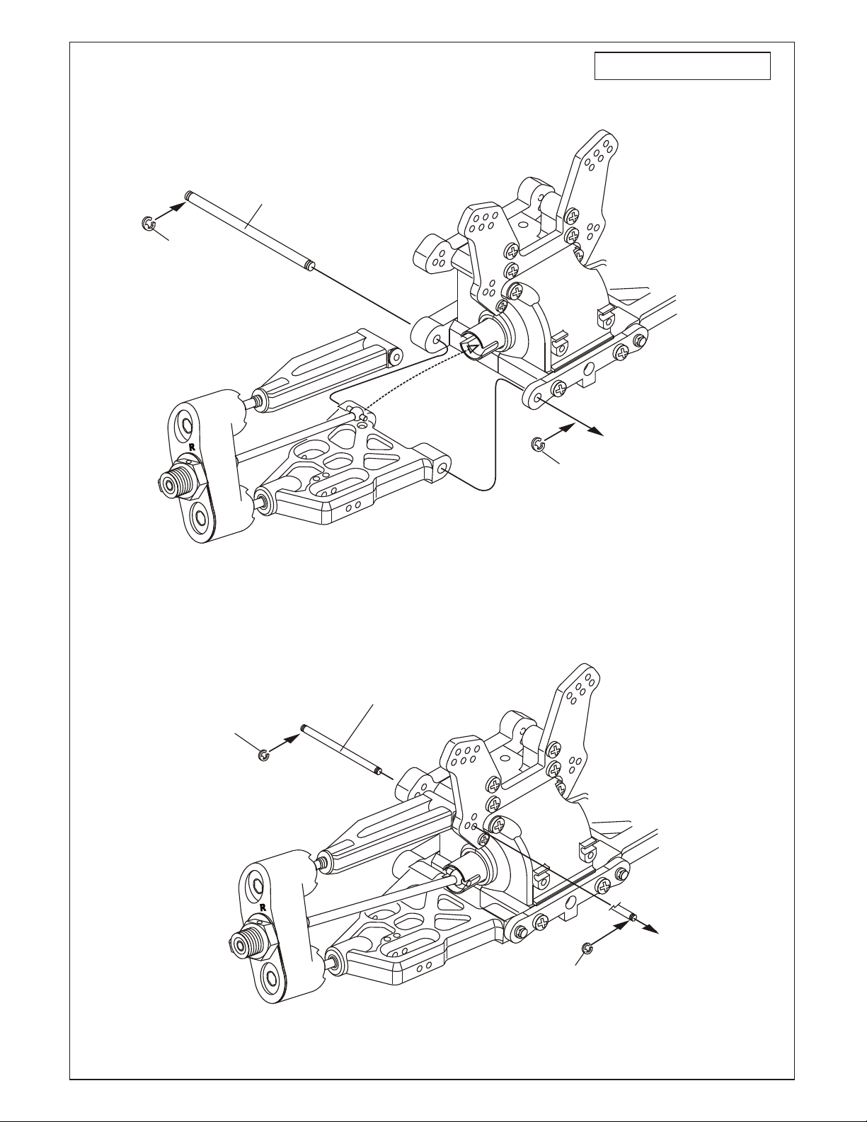
ASSEMBLY OF THE BRAKE LINKAGE INTO
BRAKE ROD
10300
Alum.
Stopper
5mm
Fuel
Tube
3X3mm
Set Screw
5mm
Fuel
Tube
*Snap On.
* Align throttle servo same
as shown.
Brake
Idle
Position
Full Throttle
*use the screw
provided With your radio.
ALIGN THROTTLE SERVO AND BRAKE SAME AS SHOWN
Engine at idle
( Neutral Position )
Brake is not on
( Braking Position )
USING BREAK ADJUST NUT
Loosen
* Tighten or loose the adjuster nut
will change the brake.
Tighten
Tighten
Less Brake
Loosen
More Brake
Loose
* Tighten or loose the adjuster nut
will change the brake.
Tighten
Less Brake
More Brake
Brake is on
Brake Adjust Nut
( Full Throttle Position )
Engine at full throttle
Brake is not on

SHOCK ASSEMBLY
32235
Shock Piston.........4
40059
14.7mm O-Ring....4
32237
1mm Washer.............4
32237
2mm Washer..........4
J-47C
Spring Adjuster....4
40060
2.5mm Nylon Nut........4
* Be careful not to damage shock shaft.
49041
Spring
Adjuster,
Orange
40059
14.7mm
Fit the O-ring into groove.
O-Ring
Make a PAIR for front
32237
7mm R-Ring
40056
Shock Plastic
Rod End
Make a PAIR for rear
40056
Shock Plastic
Rod End
32237
3.5mm
O-Ring
49041
Spring
Adjuster,
Orange
APPLY OIL TO SHOCK BODY
BEFORE INSTALLING COLLAR
32237
1mm
Washer
40076
Shock
Cylinder
32237
2mm
Washer
40077
Shock
Cylinder
Oil Seal
40054
Short Shaft
40055
Short Shaft
* Assembly 2 pieces of the
shock shaft for front and
rear.
40060
2.5mm
Nylon Nut
2.6 x 5mm
* Short shaft
for front.
* Long shaft
for rear.
Washer
32235
Shock
Piston
FILLING THE SHOCKS WITH OIL
1. Pull down piston and pour oil into
shock cylinder. Remove air bubbles
by slowly moving piston up and down.
OIL
*Leave 3mm.
UP
down.
*Move Slowly.
ASSEMBLY OF THE SPRING
OPTION:
40069 - Black, Stock, Spring Set
40070 - Green, Soft Set
40071 - Blue, Med. Set
40072 - White, Hard Set
30411
6mm Ball
2. Pull down piston, attach pressure top
and shock oil overflow with tissue
paper.
3. Tighten up shock cap.
40093
Shock Cap
Hard Coated
32033
Pressure Top
Fit into the groove.
*
40063
Spring Holder
OPTION:
40063 - CNC Alum Spring Holder, Orange
40069
Black
Shock Spring
4. Assembly the dust cover.
40058
Shock Shaft
Dust Cover
* Cut 6mm for front.
* Push 6mm ball joint
into ball end.
40052 - Front Shock Set
40053 - Rear Shock Set

ASSEMBLY OF THE FRONT SHOCK ABSORBER
3x25mm
Cap Screw
3 x 20mm
Cap Screw
ASSEMBLY OF THE REAR SHOCK ABSORBER
3x25mm
Cap Screw
36610
Shock Upper Fixing
Plastic
Bushing
35313
3mm
Nylon Nut
* Take the plastic bushing
from the shock plastic
parts tree.
Assembly of the right and left hand side
are the same.
3 x 20mm
Cap Screw..........2
M3
Nylon Nut..........2
3 X 25mm
Cap Screw..........2
36610
Shock Support.....2
Assembly of the right and left hand side
are the same.
3 x 20mm
Cap Screw..........2
M3
Nylon Nut..........2
3 X 25mm
Cap Screw..........2
36610
Shock Support.....2
ASSEMBLY OF THE TIRES AND WHEELS
86062
X Equal Pin
Tire
3 x 20mm
Cap Screw
86035
wheel
36610
Shock Upper Fixing
Plastic
Bushing
3mm
Nylon Nut
81095
Inner Sponge
INS
GL
TANT
UE
* Apply instant glue into
the groove of the wheel.

ASSEMBLY OF THE WHEELS ONTO
FRONT KNUCKLE ARM AND REAR HUB
15073
Orange
Wheel Nut
15073
Orange
Wheel Nut
Assembly of the right and left hand side
are the same.
86044 - Red
86045 - White
86046 - Lime
86047 - Yellow
86048 - Black
86049 - Chrome
17mm Dual Spoke,
2 pairs (8 wheels) per Bag.
ASSEMBLY OF THE WING
* Drill two 7mm holes
for mounting.
25mm
5
10152025
25mm
0
40084
Wing, Yellow
5
10 15 20 25
40083 - Wing White
40084 - Wing Yellow
40085 - Wing Red
40086 - Wing Lime
40087 - Wing White
OPTION:
40027 - CNC Alum
Countersunk
Wing Washer, Orange
3x12mm
Screw
40027
Countersunk
Plastic Washer
*Upper Deck Of
The Wing.
* Check the hole spacing on the underside.
OPTION:
49042
CNC Alum. Wing Washer
Orange, 2 pcs.

SET-UP GUIDE
RIDE HEIGHT ADJUSTMENT
2mm
Hex Screw
FOR A STICK PACK BATTERY
* Use tape to secure the battery.
40048
Stick Pack
Battery Holder
(5 Cell)
10211
Stick Pack
Battery(5 Cell)
( Not Included.)
3x12mm
Screw
40048
Battery Holder
3x12mm
Screw
Mount
3x12mm
Screw
Tape
3x12mm
Screw
* Insert battery wire into
receiver box and connect to
the switch.
Use a 2mm hex screw to adjust the ride height.
Screwing in the 4x10mm set screw....Ride height becomes lower.
Uncsrewing the 4x10mm set screw..Ride height becomes higher.
Soft
Firm
1 2 3
1 2
Soft
Firm


ENGINE BREAK-IN AND TUNNING
(BREAK-IN THE ENGINE BEFORE DRIVING THE CAR!)
• Choose a wide clear outdoor location with low dirt and dust.
• Set the car on box or holder with wheels off the ground.
• Turn on radio and car. Make sure throttle is at idle position.
• Fill fuel tank and set master engine needle.
• Prime fuel line and Heat glow plug before pull starting engine.
• When started, let engine fast idle for two tanks of fuel.
STARTING OF THE ENGINE
How to start the engine:
1. Turn on transmitter and then receiver.
2. Fill fuel tank with fuel bottle.
3. Connect 1.2V glow plug starter.
4. Start engine with 12V starter or starter box
( Note the direction of the starter.)
5. After the engine be started, remove the
1.2V glow plug starter.
* Follow the engine manufacturer instruction manuals
regarding engine set-up, carburetor and maintenance.
WOOD BLOCK
OPTIONAL OFNA CAR STANDS
* To start the engine, use hand held starter
motor or starter box.
#10250
Starter Box
12V Starter
Rubber wheel turns engine
flywheel.
1.2V
Glow Plug
Starter
Connect with 12V battery
* Note the direction of the
starter.

TUNING AFTER BREAK-IN
Close master needle by turning clockwise until it stops.
Then open needle by turning counterclockwise 3 turns
(rich setting).
Adjust low end needle for best throttle response. Use only
small turns. From idle, give it full throttle, if throttle is slow
lean out needle until good.
Lean
Rich
When running car, adjust carb with 1/8 clockwise turns,
slowly leaner, until the top speed good. Check engine
temp, if possible, for no more 250 degrees.
Adjust barrel stop so it will not close, accept for a small gap.
This gap will be the idle setting. You will notice the idle will
increase with a wide gap.
Idle adjuster screw &
Barrel Stop

APPENDIX PAGES
 Loading...