

Page 1
Model 920 / 921
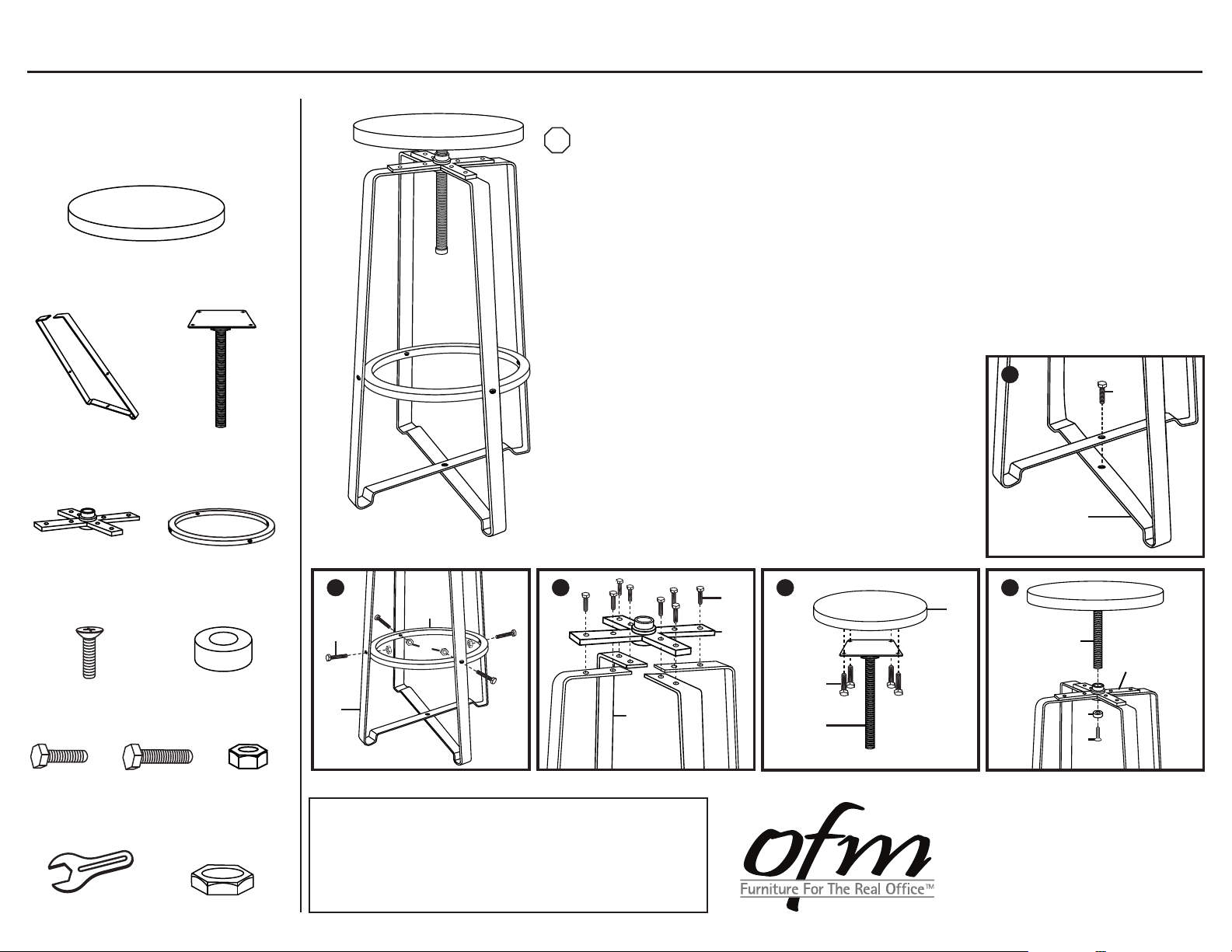
Parts Listing
A
Stool Seat
1 Unit
B
Legs
2 Units
D
Cross Bracket
1 Unit
C
Threaded Rod Mechanism
1 Unit
E
Foot Ring
1 Unit
Assembly Instructions
Tools Needed: Phillips Head Screwdriver, Adjustable Wrench, 13mm Socket Wrench
STOP
Please read all instructions before assembly.
Step 1: Connect both Legs (B) by inserting Short Bolt (H) through crossed Legs (B) using a socket
or adjustable wrench. Hand tighten only.
Step 2: Attach Foot Ring (E) by aligning its holes with those on the Legs (B). Insert Long Bolts (I)
through and secure with 12 mm Nuts (J) using a socket wrench and adjustable wrench.
Step 3: Secure Legs (B) by placing Cross Bracket (D) on top, lining up the bars, and inserting
Short Bolts (H) down through Bracket (D) and into the Legs (B) as shown.
Hand tighten only.
Step 4: Attach Threaded Rod Mechanism (C) to Stool Seat (A)
by inserting Short Bolts (H) through the plate on the
Mechanism (C) and into bottom of the Stool Seat (A).
Securely tighten all bolts on base.
Step 5: Insert Threaded Rod Mechanism (C) down through
the hole in the Cross Bracket (D).
Optional Stationary Instructions: To fix the stool
at one stationary height, screw the Stationary Nut (L)
onto the bottom of the Threaded Rod Mechanism (C)
and tighten it at the stool height you desire.
Secure by attaching Rod End Cap (G) using
the Rod Screw (F).
1
H
B
Rod Screw
1 Unit
H
Short Bolt
13 Units
12 mm Wrench
1 Unit
F
K
I
Long Bolt
4 Units
G
Rod End Cap
1 Unit
J
12 mm Nut
4 Units
L
Stationary Nut
(optional)
1 Unit
2
3
E
I
J
B
WEIGHT CAPACITY: 250 lbs.
Assembly Notes:
During assembly, hand tighten screws only. When all screws
are in place, you may then tighten all screws completely.
CAUTION:
1. Do not use this stool as a step ladder.
2. Check for loose screws and tighten them every 6 months.
B
1.28.2013
H
D
4
5
A
C
D
H
C
G
F
161 Tradition Trail, Holly Springs, NC, 27540
800-520-7471 (voice)
919- 303-6389 (voice)
support@ofminc.com
919-362-4765 (fax)
www.ofminc.com
 Loading...