

Page 1
Model 660 Executive Low-Back Task Chair
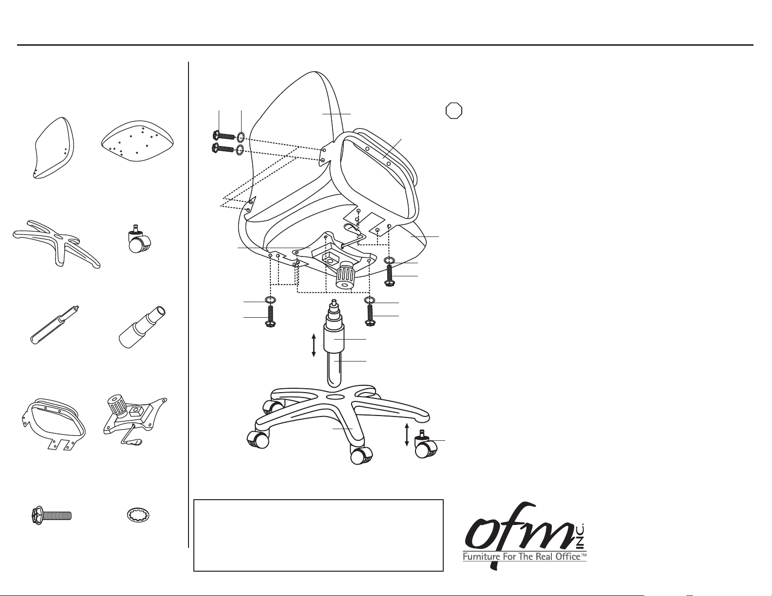
Parts Listing
A
Chair Back
1 Unit
C
Chair Base
1 Unit
E
Gas Lift
1 Unit
G
Chair Arms
2 Units
B
Chair Seat
2 Units
D
Casters
5 Units
F
Telescopic Bellows
1 Unit
H
Seat Mechanism
1 Unit
Assembly Instructions
J
I
A
G
B
H
J
I
J
I
J
I
F
E
Tools Needed: Phillips Head Screwdriver
STOP
Please read all instructions before assembly.
Step 1: Insert Casters (D) into Chair Base (C).
Step 2: Insert Gas Lift (E) into Chair Base (C) and cover with
Telescopic Bellows (F).
Step 3: Place Chair Seat (B) upside down on a level,
non-abrasive surface. Align holes in Seat Mechanism (H)
with holes in bottom of Chair Seat (B).
Step 4: Place four Washers (J) onto four Screws (I) and insert
through the holes in the Seat Mechanism (H) and into
the Chair Seat (B). Tighten with screwdriver.
Step 5: Attach Chair Arms (G) to Chair Seat (B) using Washers (J)
and Screws (I). Tighten with screwdriver.
Step 6: Attach Chair Back (A) to Chair Arms (G) by aligning holes
in both, and attach using Washers (J) and Screws (I).
Tighten with screwdriver.
Step 7: Carefully place Chair Seat (B) and attached Seat
Mechanism (H) onto the Gas Lift (E), aligning the hole in
the Mechanism (H) with the top of the Gas Lift (E). Press
down firmly to secure.
Step 8: Carefully sit on Chair Seat (B) to make sure the Gas Lift (E)
is properly inserted into the Chair Base (C).
I
8x30mm Screw
16 Units
J
Washer
16 Units
C
WEIGHT CAPACITY: 250 lbs.
Assembly Notes:
During assembly, hand tighten screw only when all screws
are in place, you may then tighten all screws completely.
CAUTION:
1. Do not use this chair as a step ladder.
2. Check for loose screws and tighten them every 6 months.
06.23.2010
D
161 Tradition Trail Holly Springs, NC, 27540
800-520-7471 (voice)
919- 303-6389 (voice)
support@ofminc.com
919-362-4765 (fax)
www.ofminc.com
 Loading...