

Page 1
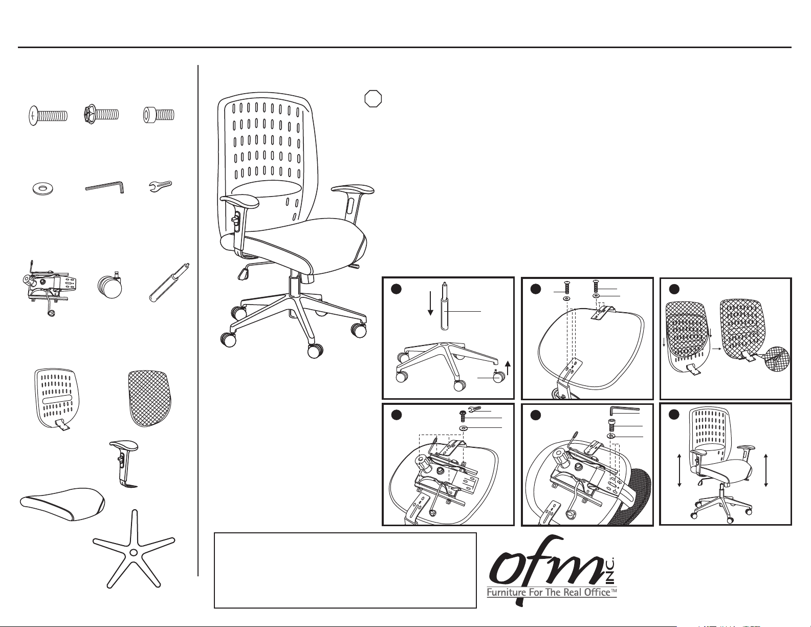
Model 654 Vision Executive Chair
B
D
Parts Listing
A
6 Units
D
13 Units
G
Seat Mechanism
1 Unit
B
4 Units
E
1 Unit
H
Casters
5 Units
C
3 Units
F
1 Unit
I
Gas Lift
1 Unit
Assembly Instructions
Tools Needed: Phillips Head Screwdriver
STOP
Please read all instructions before assembly.
Step 1: Insert Casters (H) into Swivel Base. Insert Gas Lift (I) into Swivel Base (N).
Step 2: Attach Adjustable Arms (M) to Seat Cushion (L) using screws (A) and washers (D).
Tighten screws with phillips head screwdriver.
Step 3: Cover plastic Seat Back (J) with replaceable Slipcover (K), and place mount plate
through slipcover before securely zipping.
Step 4: Attach Seat Mechanism (G) to the Seat Cushion (L) with 4 Bolts (B) and
washers (D), using the Wrench (F) that is provided.
Step 5: Insert mounting plate on Seat Back (J) into Seat Mechanism (G) and attach with
3 Screws (C), using Allen Wrench (E) that is provided.
Step 6: Take entire chair frame and place Seat Mechanism (G) onto Gas Lift (I), and press
down firmly to secure.
J
Seat Back
1 Unit
L
Seat Cushion
1 Unit
K
Slipcover
1 Unit
Adjustable Arms
2 Units
Swivel Base
1 Unit
1
I
H
4
M
N
F
2
A
5
A
D
3
E
6
C
D
WEIGHT CAPACITY: 250 lbs.
Assembly Notes:
During assembly, hand tighten screw only when all screws
are in place, you may then tighten all screws completely.
CAUTION:
1. Do not use this chair as a step ladder.
2. Check for loose screws and tighten them every 6 months.
161 Tradition Trail Holly Springs, NC, 27540
800-520-7471 (voice)
919- 303-6389 (voice)
support@ofminc.com
919-362-4765 (fax)
www.ofminc.com
 Loading...