

Page 1
Models 130/130-AA3/130-AA3-DK/130-DK Modern Mesh Ergonomic Task Chair
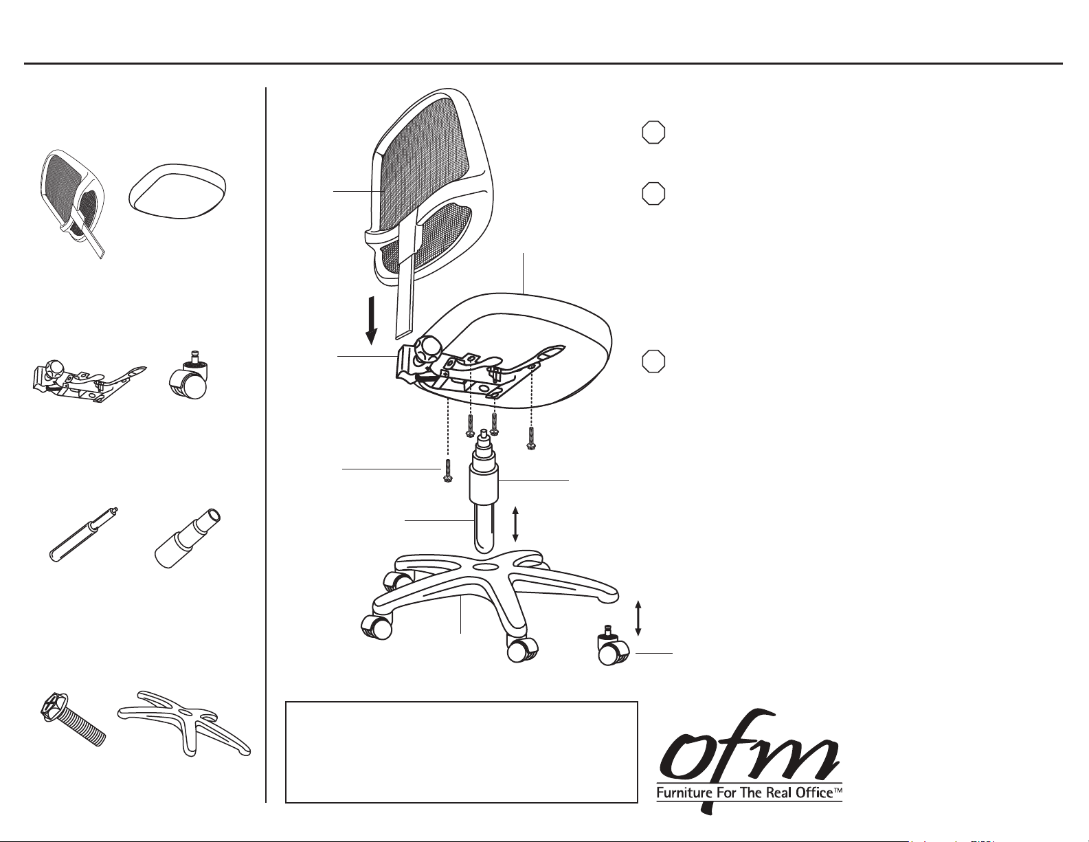
Parts Listing
Assembly Instructions:
A
Chair Back
1 Unit
C
Seat Mechanism
1 Unit
E
Gas Lift
1 Unit
G
8x20mm Screws
4 Units
B
Chair Seat
1 Unit
D
Casters
5 Units
F
Telescopic Bellows
1 Unit
H
Chair Base
1 Unit
A
C
G
E
WEIGHT CAPACITY: 250 lbs.
H
Tools Needed: Philips Head Screwdriver
STOP
Please read all instructions before assembly.
Step 1: Insert Casters (D) into Base (H).
If you are assembling a model with a DK Foot Ring please proceed
STOP
to subsequent pages for drafting kit assembly instructions.
Step 2: Insert Gas Lift (E) into Base (H).
B
F
Step 3: Cover Gas Lift (E) with 3 piece Telescopic Bellows (F).
Step 4: Place Chair Seat (B) upside down on a level,
non-abrasive surface and align pre-drilled holes in
Seat Mechanism (C), with holes in Chair Seat.
Step 5: Insert four 30mm Screws (G) through holes in the
Seat Mechanism (C), and into the Chair Seat (B).
Tighten with screwdriver.
If you are assembling a model with optional Adjustable Arms please
STOP
proceed to subsequent pages for armrest assembly instructions.
Step 6: Carefully place Chair Seat (B) with attached Seat
Mechanism (C) onto the Gas Lift (E), aligning the hole
in the Seat Mechanism with Gas Lift. Press down
on Chair Seat to secure onto Base (H).
Step 7: Slide Chair Back (A) with attached back support bar
into the slot on Seat Mechanism (C).
Step 8: Hand tighten tension knob on Seat Mechanism (C)
until the Chair Back (A) is properly secured.
Step 9: Carefully sit on chair to make sure the Gas Lift (E)
is properly inserted into the Base (H).
Step 10: Operate the Gas Lift lever on the Seat Mechanism (C),
to be sure unt is working properly.
Step 11: Readjust Chair Back (A) by loosening tension knob
on the Seat Mechanism (C) accordingly, for your
personal comfort.
D
Assembly Notes:
During assembly, hand tighten screws only. When all screws
are in place, you may then tighten all screws completely.
CAUTION:
1. Do not use this chair as a step ladder.
2. Check for loose screws and tighten them every 6 months.
12.12.13
161 Tradition Trail, Holly Springs, NC, 27540
800-520-7471 (voice) 919-362-4765 (fax)
919-303-6389 (voice) www.ofminc.com
[email protected]
Page 2
Model AA-3 Adjustable Arms
Parts Listing
A
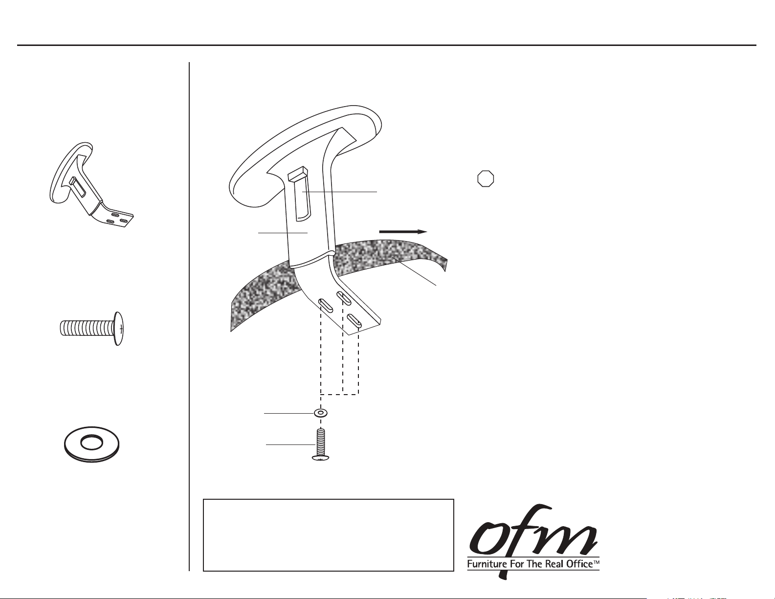
AA-3 Adjustable Armrest
2 Units
A
B
M6x30mm Screw
6 Units
Height Adjustment
Button
Forward
Chair Seat
Assembly Instructions
Tools Needed: Phillips Head Screwdriver
STOP
Please read all instructions before assembly.
Step 1: Turn Chair Seat upside down and place on a
clean, non-abrasive surface.
Step 2: Align the pre-drilled holes in the Adjustable Armrest (A)
with the holes in the bottom of the Chair Seat,
making sure that the arms face the correct direction.
Step 3: Place three Washers (C) onto three M6x30mm
Hex Screws (B) and insert through the Armrest (A)
holes and into the Chair Seat.
Step 4: Tighten Screws (B) using wrench or screwdriver.
It is recommended that to assure screws are secure,
a screwdriver is used to tighten.
C
Washer
6 Units
C
B
WEIGHT CAPACITY: 250 lbs.
Assembly Notes:
During assembly, hand tighten screws only. When all screws
are in place, you may then tighten all screws completely.
CAUTION:
1. Do not use this chair as a step ladder.
2. Check for loose screws and tighten them every 6 months.
To Adjust Arms:
Pull up on the Height Adjustment Button
and slide to desired height.
161 Tradition Trail, Holly Springs, NC, 27540
800-520-7471 (voice) 919-362-4765 (fax)
919-303-6389 (voice) www.ofminc.com
[email protected]
12.12.13
Page 3
Model DK-2 Drafting Kit Assembly
Parts Listing
A
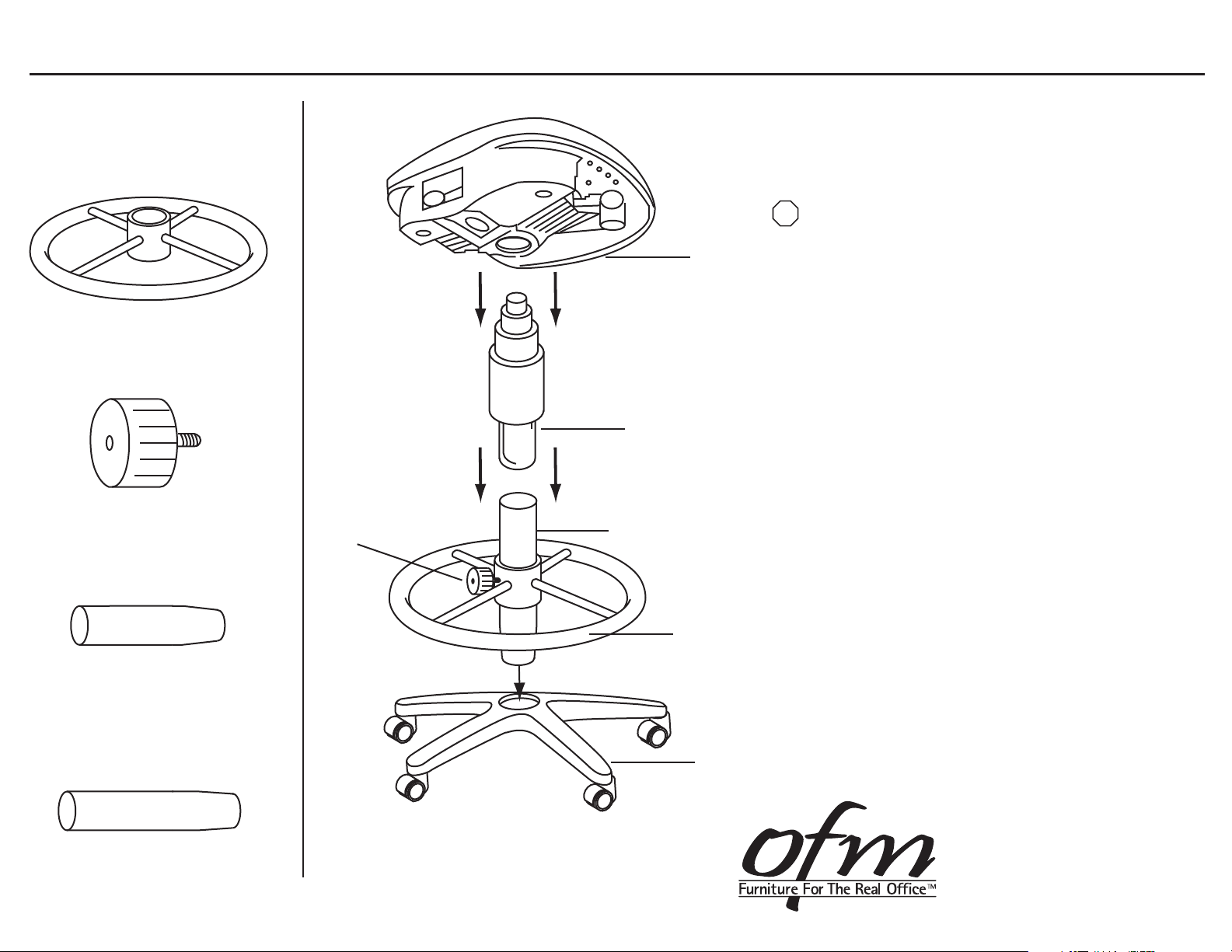
Circular Foot Rest
1 Unit
B
Tension Knob
1 Unit
C
9” Extension Tube
1 Unit
B
Gas Lift
C / D
Chair Seat
Assembly Instructions
STOP
Please read all instructions before assembly.
Prior to assembly, select only one Extension Tube
for desired Height
9” Extension Tube will change seat height from 24”-28”
12” Extension Tube will change seat height from 27-31”
Step 1: Slide the Circular Foot Rest (A) over the smaller
tapered end of your chosen Extension Tube (C / D).
Step 2: Screw in Tension Knob (B) and tighten to lock
Foot Rest (A).
Step 3: Place the tapered end of Extension Tube (C / D)
into your Chair Base.
Step 4: Insert bottom of Gas Lift Cylinder into the top
end of the Extension Tube (C / D).
Step 5: Place the Chair Seat onto the Gas Lift by
inserting top of Gas Lift into the hole in the
Seat Mechanism.
Step 6: Press down firmly to secure the chair.
Note: Save the left over extension tube for future use.
D
12” Extension Tube
1 Unit
A
Chair Base
161 Tradition Trail Holly Springs, NC, 27540
800-520-7471 (voice)
919- 303-6389 (voice)
[email protected]
919-362-4765 (fax)
www.ofminc.com
 Loading...